EP3580045B1 - Ultraschall-verarbeitungssystem, verstärker und verfahren - Google Patents
Ultraschall-verarbeitungssystem, verstärker und verfahren Download PDFInfo
- Publication number
- EP3580045B1 EP3580045B1 EP17705830.2A EP17705830A EP3580045B1 EP 3580045 B1 EP3580045 B1 EP 3580045B1 EP 17705830 A EP17705830 A EP 17705830A EP 3580045 B1 EP3580045 B1 EP 3580045B1
- Authority
- EP
- European Patent Office
- Prior art keywords
- medium
- longitudinal axis
- cavity
- booster
- sonotrode
- Prior art date
- Legal status (The legal status is an assumption and is not a legal conclusion. Google has not performed a legal analysis and makes no representation as to the accuracy of the status listed.)
- Active
Links
Images


Classifications
-
- B—PERFORMING OPERATIONS; TRANSPORTING
- B29—WORKING OF PLASTICS; WORKING OF SUBSTANCES IN A PLASTIC STATE IN GENERAL
- B29C—SHAPING OR JOINING OF PLASTICS; SHAPING OF MATERIAL IN A PLASTIC STATE, NOT OTHERWISE PROVIDED FOR; AFTER-TREATMENT OF THE SHAPED PRODUCTS, e.g. REPAIRING
- B29C65/00—Joining or sealing of preformed parts, e.g. welding of plastics materials; Apparatus therefor
- B29C65/02—Joining or sealing of preformed parts, e.g. welding of plastics materials; Apparatus therefor by heating, with or without pressure
- B29C65/08—Joining or sealing of preformed parts, e.g. welding of plastics materials; Apparatus therefor by heating, with or without pressure using ultrasonic vibrations
-
- B—PERFORMING OPERATIONS; TRANSPORTING
- B29—WORKING OF PLASTICS; WORKING OF SUBSTANCES IN A PLASTIC STATE IN GENERAL
- B29C—SHAPING OR JOINING OF PLASTICS; SHAPING OF MATERIAL IN A PLASTIC STATE, NOT OTHERWISE PROVIDED FOR; AFTER-TREATMENT OF THE SHAPED PRODUCTS, e.g. REPAIRING
- B29C66/00—General aspects of processes or apparatus for joining preformed parts
- B29C66/01—General aspects dealing with the joint area or with the area to be joined
- B29C66/03—After-treatments in the joint area
- B29C66/034—Thermal after-treatments
- B29C66/0342—Cooling, e.g. transporting through welding and cooling zone
-
- B—PERFORMING OPERATIONS; TRANSPORTING
- B23—MACHINE TOOLS; METAL-WORKING NOT OTHERWISE PROVIDED FOR
- B23K—SOLDERING OR UNSOLDERING; WELDING; CLADDING OR PLATING BY SOLDERING OR WELDING; CUTTING BY APPLYING HEAT LOCALLY, e.g. FLAME CUTTING; WORKING BY LASER BEAM
- B23K1/00—Soldering, e.g. brazing, or unsoldering
- B23K1/06—Soldering, e.g. brazing, or unsoldering making use of vibrations, e.g. supersonic vibrations
-
- B—PERFORMING OPERATIONS; TRANSPORTING
- B23—MACHINE TOOLS; METAL-WORKING NOT OTHERWISE PROVIDED FOR
- B23K—SOLDERING OR UNSOLDERING; WELDING; CLADDING OR PLATING BY SOLDERING OR WELDING; CUTTING BY APPLYING HEAT LOCALLY, e.g. FLAME CUTTING; WORKING BY LASER BEAM
- B23K20/00—Non-electric welding by applying impact or other pressure, with or without the application of heat, e.g. cladding or plating
- B23K20/10—Non-electric welding by applying impact or other pressure, with or without the application of heat, e.g. cladding or plating making use of vibrations, e.g. ultrasonic welding
- B23K20/106—Features related to sonotrodes
-
- B—PERFORMING OPERATIONS; TRANSPORTING
- B29—WORKING OF PLASTICS; WORKING OF SUBSTANCES IN A PLASTIC STATE IN GENERAL
- B29C—SHAPING OR JOINING OF PLASTICS; SHAPING OF MATERIAL IN A PLASTIC STATE, NOT OTHERWISE PROVIDED FOR; AFTER-TREATMENT OF THE SHAPED PRODUCTS, e.g. REPAIRING
- B29C66/00—General aspects of processes or apparatus for joining preformed parts
- B29C66/01—General aspects dealing with the joint area or with the area to be joined
- B29C66/05—Particular design of joint configurations
- B29C66/20—Particular design of joint configurations particular design of the joint lines, e.g. of the weld lines
- B29C66/21—Particular design of joint configurations particular design of the joint lines, e.g. of the weld lines said joint lines being formed by a single dot or dash or by several dots or dashes, i.e. spot joining or spot welding
-
- B—PERFORMING OPERATIONS; TRANSPORTING
- B29—WORKING OF PLASTICS; WORKING OF SUBSTANCES IN A PLASTIC STATE IN GENERAL
- B29C—SHAPING OR JOINING OF PLASTICS; SHAPING OF MATERIAL IN A PLASTIC STATE, NOT OTHERWISE PROVIDED FOR; AFTER-TREATMENT OF THE SHAPED PRODUCTS, e.g. REPAIRING
- B29C66/00—General aspects of processes or apparatus for joining preformed parts
- B29C66/01—General aspects dealing with the joint area or with the area to be joined
- B29C66/349—Cooling the welding zone on the welding spot
- B29C66/3494—Cooling the welding zone on the welding spot while keeping the welding zone under pressure
-
- B—PERFORMING OPERATIONS; TRANSPORTING
- B29—WORKING OF PLASTICS; WORKING OF SUBSTANCES IN A PLASTIC STATE IN GENERAL
- B29C—SHAPING OR JOINING OF PLASTICS; SHAPING OF MATERIAL IN A PLASTIC STATE, NOT OTHERWISE PROVIDED FOR; AFTER-TREATMENT OF THE SHAPED PRODUCTS, e.g. REPAIRING
- B29C66/00—General aspects of processes or apparatus for joining preformed parts
- B29C66/80—General aspects of machine operations or constructions and parts thereof
- B29C66/81—General aspects of the pressing elements, i.e. the elements applying pressure on the parts to be joined in the area to be joined, e.g. the welding jaws or clamps
- B29C66/814—General aspects of the pressing elements, i.e. the elements applying pressure on the parts to be joined in the area to be joined, e.g. the welding jaws or clamps characterised by the design of the pressing elements, e.g. of the welding jaws or clamps
- B29C66/8141—General aspects of the pressing elements, i.e. the elements applying pressure on the parts to be joined in the area to be joined, e.g. the welding jaws or clamps characterised by the design of the pressing elements, e.g. of the welding jaws or clamps characterised by the surface geometry of the part of the pressing elements, e.g. welding jaws or clamps, coming into contact with the parts to be joined
- B29C66/81411—General aspects of the pressing elements, i.e. the elements applying pressure on the parts to be joined in the area to be joined, e.g. the welding jaws or clamps characterised by the design of the pressing elements, e.g. of the welding jaws or clamps characterised by the surface geometry of the part of the pressing elements, e.g. welding jaws or clamps, coming into contact with the parts to be joined characterised by its cross-section, e.g. transversal or longitudinal, being non-flat
- B29C66/81421—General aspects of the pressing elements, i.e. the elements applying pressure on the parts to be joined in the area to be joined, e.g. the welding jaws or clamps characterised by the design of the pressing elements, e.g. of the welding jaws or clamps characterised by the surface geometry of the part of the pressing elements, e.g. welding jaws or clamps, coming into contact with the parts to be joined characterised by its cross-section, e.g. transversal or longitudinal, being non-flat being convex or concave
- B29C66/81423—General aspects of the pressing elements, i.e. the elements applying pressure on the parts to be joined in the area to be joined, e.g. the welding jaws or clamps characterised by the design of the pressing elements, e.g. of the welding jaws or clamps characterised by the surface geometry of the part of the pressing elements, e.g. welding jaws or clamps, coming into contact with the parts to be joined characterised by its cross-section, e.g. transversal or longitudinal, being non-flat being convex or concave being concave
-
- B—PERFORMING OPERATIONS; TRANSPORTING
- B29—WORKING OF PLASTICS; WORKING OF SUBSTANCES IN A PLASTIC STATE IN GENERAL
- B29C—SHAPING OR JOINING OF PLASTICS; SHAPING OF MATERIAL IN A PLASTIC STATE, NOT OTHERWISE PROVIDED FOR; AFTER-TREATMENT OF THE SHAPED PRODUCTS, e.g. REPAIRING
- B29C66/00—General aspects of processes or apparatus for joining preformed parts
- B29C66/80—General aspects of machine operations or constructions and parts thereof
- B29C66/81—General aspects of the pressing elements, i.e. the elements applying pressure on the parts to be joined in the area to be joined, e.g. the welding jaws or clamps
- B29C66/814—General aspects of the pressing elements, i.e. the elements applying pressure on the parts to be joined in the area to be joined, e.g. the welding jaws or clamps characterised by the design of the pressing elements, e.g. of the welding jaws or clamps
- B29C66/8141—General aspects of the pressing elements, i.e. the elements applying pressure on the parts to be joined in the area to be joined, e.g. the welding jaws or clamps characterised by the design of the pressing elements, e.g. of the welding jaws or clamps characterised by the surface geometry of the part of the pressing elements, e.g. welding jaws or clamps, coming into contact with the parts to be joined
- B29C66/81427—General aspects of the pressing elements, i.e. the elements applying pressure on the parts to be joined in the area to be joined, e.g. the welding jaws or clamps characterised by the design of the pressing elements, e.g. of the welding jaws or clamps characterised by the surface geometry of the part of the pressing elements, e.g. welding jaws or clamps, coming into contact with the parts to be joined comprising a single ridge, e.g. for making a weakening line; comprising a single tooth
- B29C66/81429—General aspects of the pressing elements, i.e. the elements applying pressure on the parts to be joined in the area to be joined, e.g. the welding jaws or clamps characterised by the design of the pressing elements, e.g. of the welding jaws or clamps characterised by the surface geometry of the part of the pressing elements, e.g. welding jaws or clamps, coming into contact with the parts to be joined comprising a single ridge, e.g. for making a weakening line; comprising a single tooth comprising a single tooth
-
- B—PERFORMING OPERATIONS; TRANSPORTING
- B29—WORKING OF PLASTICS; WORKING OF SUBSTANCES IN A PLASTIC STATE IN GENERAL
- B29C—SHAPING OR JOINING OF PLASTICS; SHAPING OF MATERIAL IN A PLASTIC STATE, NOT OTHERWISE PROVIDED FOR; AFTER-TREATMENT OF THE SHAPED PRODUCTS, e.g. REPAIRING
- B29C66/00—General aspects of processes or apparatus for joining preformed parts
- B29C66/80—General aspects of machine operations or constructions and parts thereof
- B29C66/81—General aspects of the pressing elements, i.e. the elements applying pressure on the parts to be joined in the area to be joined, e.g. the welding jaws or clamps
- B29C66/814—General aspects of the pressing elements, i.e. the elements applying pressure on the parts to be joined in the area to be joined, e.g. the welding jaws or clamps characterised by the design of the pressing elements, e.g. of the welding jaws or clamps
- B29C66/8141—General aspects of the pressing elements, i.e. the elements applying pressure on the parts to be joined in the area to be joined, e.g. the welding jaws or clamps characterised by the design of the pressing elements, e.g. of the welding jaws or clamps characterised by the surface geometry of the part of the pressing elements, e.g. welding jaws or clamps, coming into contact with the parts to be joined
- B29C66/81431—General aspects of the pressing elements, i.e. the elements applying pressure on the parts to be joined in the area to be joined, e.g. the welding jaws or clamps characterised by the design of the pressing elements, e.g. of the welding jaws or clamps characterised by the surface geometry of the part of the pressing elements, e.g. welding jaws or clamps, coming into contact with the parts to be joined comprising a single cavity, e.g. a groove
-
- B—PERFORMING OPERATIONS; TRANSPORTING
- B29—WORKING OF PLASTICS; WORKING OF SUBSTANCES IN A PLASTIC STATE IN GENERAL
- B29C—SHAPING OR JOINING OF PLASTICS; SHAPING OF MATERIAL IN A PLASTIC STATE, NOT OTHERWISE PROVIDED FOR; AFTER-TREATMENT OF THE SHAPED PRODUCTS, e.g. REPAIRING
- B29C66/00—General aspects of processes or apparatus for joining preformed parts
- B29C66/80—General aspects of machine operations or constructions and parts thereof
- B29C66/81—General aspects of the pressing elements, i.e. the elements applying pressure on the parts to be joined in the area to be joined, e.g. the welding jaws or clamps
- B29C66/816—General aspects of the pressing elements, i.e. the elements applying pressure on the parts to be joined in the area to be joined, e.g. the welding jaws or clamps characterised by the mounting of the pressing elements, e.g. of the welding jaws or clamps
- B29C66/8167—Quick change joining tools or surfaces
-
- B—PERFORMING OPERATIONS; TRANSPORTING
- B29—WORKING OF PLASTICS; WORKING OF SUBSTANCES IN A PLASTIC STATE IN GENERAL
- B29C—SHAPING OR JOINING OF PLASTICS; SHAPING OF MATERIAL IN A PLASTIC STATE, NOT OTHERWISE PROVIDED FOR; AFTER-TREATMENT OF THE SHAPED PRODUCTS, e.g. REPAIRING
- B29C66/00—General aspects of processes or apparatus for joining preformed parts
- B29C66/80—General aspects of machine operations or constructions and parts thereof
- B29C66/81—General aspects of the pressing elements, i.e. the elements applying pressure on the parts to be joined in the area to be joined, e.g. the welding jaws or clamps
- B29C66/818—General aspects of the pressing elements, i.e. the elements applying pressure on the parts to be joined in the area to be joined, e.g. the welding jaws or clamps characterised by the cooling constructional aspects, or by the thermal or electrical insulating or conducting constructional aspects of the welding jaws or of the clamps ; comprising means for compensating for the thermal expansion of the welding jaws or of the clamps
- B29C66/8181—General aspects of the pressing elements, i.e. the elements applying pressure on the parts to be joined in the area to be joined, e.g. the welding jaws or clamps characterised by the cooling constructional aspects, or by the thermal or electrical insulating or conducting constructional aspects of the welding jaws or of the clamps ; comprising means for compensating for the thermal expansion of the welding jaws or of the clamps characterised by the cooling constructional aspects
- B29C66/81811—General aspects of the pressing elements, i.e. the elements applying pressure on the parts to be joined in the area to be joined, e.g. the welding jaws or clamps characterised by the cooling constructional aspects, or by the thermal or electrical insulating or conducting constructional aspects of the welding jaws or of the clamps ; comprising means for compensating for the thermal expansion of the welding jaws or of the clamps characterised by the cooling constructional aspects of the welding jaws
-
- B—PERFORMING OPERATIONS; TRANSPORTING
- B29—WORKING OF PLASTICS; WORKING OF SUBSTANCES IN A PLASTIC STATE IN GENERAL
- B29C—SHAPING OR JOINING OF PLASTICS; SHAPING OF MATERIAL IN A PLASTIC STATE, NOT OTHERWISE PROVIDED FOR; AFTER-TREATMENT OF THE SHAPED PRODUCTS, e.g. REPAIRING
- B29C66/00—General aspects of processes or apparatus for joining preformed parts
- B29C66/80—General aspects of machine operations or constructions and parts thereof
- B29C66/83—General aspects of machine operations or constructions and parts thereof characterised by the movement of the joining or pressing tools
- B29C66/832—Reciprocating joining or pressing tools
- B29C66/8322—Joining or pressing tools reciprocating along one axis
-
- B—PERFORMING OPERATIONS; TRANSPORTING
- B06—GENERATING OR TRANSMITTING MECHANICAL VIBRATIONS IN GENERAL
- B06B—METHODS OR APPARATUS FOR GENERATING OR TRANSMITTING MECHANICAL VIBRATIONS OF INFRASONIC, SONIC, OR ULTRASONIC FREQUENCY, e.g. FOR PERFORMING MECHANICAL WORK IN GENERAL
- B06B2201/00—Indexing scheme associated with B06B1/0207 for details covered by B06B1/0207 but not provided for in any of its subgroups
- B06B2201/70—Specific application
- B06B2201/72—Welding, joining, soldering
-
- B—PERFORMING OPERATIONS; TRANSPORTING
- B23—MACHINE TOOLS; METAL-WORKING NOT OTHERWISE PROVIDED FOR
- B23K—SOLDERING OR UNSOLDERING; WELDING; CLADDING OR PLATING BY SOLDERING OR WELDING; CUTTING BY APPLYING HEAT LOCALLY, e.g. FLAME CUTTING; WORKING BY LASER BEAM
- B23K2103/00—Materials to be soldered, welded or cut
- B23K2103/30—Organic materials
- B23K2103/42—Plastics other than composite materials
-
- B—PERFORMING OPERATIONS; TRANSPORTING
- B29—WORKING OF PLASTICS; WORKING OF SUBSTANCES IN A PLASTIC STATE IN GENERAL
- B29C—SHAPING OR JOINING OF PLASTICS; SHAPING OF MATERIAL IN A PLASTIC STATE, NOT OTHERWISE PROVIDED FOR; AFTER-TREATMENT OF THE SHAPED PRODUCTS, e.g. REPAIRING
- B29C66/00—General aspects of processes or apparatus for joining preformed parts
- B29C66/80—General aspects of machine operations or constructions and parts thereof
- B29C66/81—General aspects of the pressing elements, i.e. the elements applying pressure on the parts to be joined in the area to be joined, e.g. the welding jaws or clamps
- B29C66/816—General aspects of the pressing elements, i.e. the elements applying pressure on the parts to be joined in the area to be joined, e.g. the welding jaws or clamps characterised by the mounting of the pressing elements, e.g. of the welding jaws or clamps
-
- B—PERFORMING OPERATIONS; TRANSPORTING
- B29—WORKING OF PLASTICS; WORKING OF SUBSTANCES IN A PLASTIC STATE IN GENERAL
- B29C—SHAPING OR JOINING OF PLASTICS; SHAPING OF MATERIAL IN A PLASTIC STATE, NOT OTHERWISE PROVIDED FOR; AFTER-TREATMENT OF THE SHAPED PRODUCTS, e.g. REPAIRING
- B29C66/00—General aspects of processes or apparatus for joining preformed parts
- B29C66/90—Measuring or controlling the joining process
- B29C66/91—Measuring or controlling the joining process by measuring or controlling the temperature, the heat or the thermal flux
- B29C66/919—Measuring or controlling the joining process by measuring or controlling the temperature, the heat or the thermal flux characterised by specific temperature, heat or thermal flux values or ranges
-
- B—PERFORMING OPERATIONS; TRANSPORTING
- B29—WORKING OF PLASTICS; WORKING OF SUBSTANCES IN A PLASTIC STATE IN GENERAL
- B29C—SHAPING OR JOINING OF PLASTICS; SHAPING OF MATERIAL IN A PLASTIC STATE, NOT OTHERWISE PROVIDED FOR; AFTER-TREATMENT OF THE SHAPED PRODUCTS, e.g. REPAIRING
- B29C66/00—General aspects of processes or apparatus for joining preformed parts
- B29C66/90—Measuring or controlling the joining process
- B29C66/91—Measuring or controlling the joining process by measuring or controlling the temperature, the heat or the thermal flux
- B29C66/919—Measuring or controlling the joining process by measuring or controlling the temperature, the heat or the thermal flux characterised by specific temperature, heat or thermal flux values or ranges
- B29C66/9192—Measuring or controlling the joining process by measuring or controlling the temperature, the heat or the thermal flux characterised by specific temperature, heat or thermal flux values or ranges in explicit relation to another variable, e.g. temperature diagrams
- B29C66/91921—Measuring or controlling the joining process by measuring or controlling the temperature, the heat or the thermal flux characterised by specific temperature, heat or thermal flux values or ranges in explicit relation to another variable, e.g. temperature diagrams in explicit relation to another temperature, e.g. to the softening temperature or softening point, to the thermal degradation temperature or to the ambient temperature
- B29C66/91941—Measuring or controlling the joining process by measuring or controlling the temperature, the heat or the thermal flux characterised by specific temperature, heat or thermal flux values or ranges in explicit relation to another variable, e.g. temperature diagrams in explicit relation to another temperature, e.g. to the softening temperature or softening point, to the thermal degradation temperature or to the ambient temperature in explicit relation to Tg, i.e. the glass transition temperature, of the material of one of the parts to be joined
-
- B—PERFORMING OPERATIONS; TRANSPORTING
- B29—WORKING OF PLASTICS; WORKING OF SUBSTANCES IN A PLASTIC STATE IN GENERAL
- B29C—SHAPING OR JOINING OF PLASTICS; SHAPING OF MATERIAL IN A PLASTIC STATE, NOT OTHERWISE PROVIDED FOR; AFTER-TREATMENT OF THE SHAPED PRODUCTS, e.g. REPAIRING
- B29C66/00—General aspects of processes or apparatus for joining preformed parts
- B29C66/90—Measuring or controlling the joining process
- B29C66/92—Measuring or controlling the joining process by measuring or controlling the pressure, the force, the mechanical power or the displacement of the joining tools
- B29C66/929—Measuring or controlling the joining process by measuring or controlling the pressure, the force, the mechanical power or the displacement of the joining tools characterized by specific pressure, force, mechanical power or displacement values or ranges
Definitions
- the present invention relates to ultrasonic processing of workpieces, for example ultrasonic connecting of workpieces such as welding and/or brazing of workpieces, ultrasonic cleaning of workpieces or ultrasonic cutting of workpieces.
- Known systems for ultrasonic processing of workpieces comprise an ultrasonic sonotrode with at least one working surface for ultrasonic processing of the workpieces.
- the process of ultrasonic plastic welding applies temperatures of about 200 to 250 °C to a working surface of a sonotrode. After the welding has been completed, it is important to allow the welded workpieces to cool down below the glass temperature of the plastic material in order keep their shapes. Therefore, a welding force has to be applied until the glass temperature has been reached which usually takes several seconds. In order to speed up this process, it is necessary to have a cooling device which cools down the sonotrode and its working surface to dissipate the thermal heat stored due to the sonotrode thermal capacity.
- Several approaches have been made in the prior art in order to provide such a cooling.
- DE 42 06 584 A1 discloses a system for connecting two workpieces by ultrasound in which a working surface of a sonotrode is cooled by cooling air emitted by one or several nozzles arranged around the working surface.
- a cooling of only the outside of the sonotrode is not very effective.
- a cooling medium is externally blown across the sonotrode or it may travel through various passageways located within the sonotrode.
- a further embodiment in US 2003/0066863 A1 utilizes the use of cooling fins connected to the sonotrode to cool the sonotrode to a lower temperature.
- the sonotrode disclosed in ES 1 163 609 U contains a central bore connected to slanted channels opening out near a working surface of the sonotrode. A cooling medium can be guided through this system of bores and channels.
- the sonotrode should be replaceable by another sonotrode more easily.
- an ultrasonic processing system comprising an ultrasonic vibrator having an ultrasonic sonotrode with at least one working surface for ultrasonic processing of at least one workpiece.
- ultrasonic processing may be ultrasonic connecting of workpieces such as welding and/or brazing of workpieces, ultrasonic cleaning of workpieces or ultrasonic cutting of workpieces.
- the vibrator comprises
- the cooling medium is fed into the medium inlet, passes the vortex generator and flows through the enclosed cavity. At least a first portion of the cooling medium having flown through the enclosed cavity then flows through the cooling channel and is finally discharged through the first medium outlet.
- the system according to the present invention contains at least one vortex generator which is designed and arranged between the medium inlet and the cavity such that a swirl motion of the medium inside the cavity around the longitudinal axis can be generated.
- a vortex generator which is designed and arranged between the medium inlet and the cavity such that a swirl motion of the medium inside the cavity around the longitudinal axis can be generated.
- the Joule-Thomson effect known as such at least partially reduces the temperature of the cooling medium as it passes the vortex generator and thereby contributes to the improved heat dissipation of the present invention.
- a cooling due to the Joule-Thomson effect occurs in the vicinity of an adjacent ultrasonic converter connected to the vibrator for exciting vibrations of the ultrasonic vibrator, such a converter may also be cooled.
- the vortex generator and the enclosed cavity in the ultrasonic vibrator and in particular its sonotrode function as a vortex tube.
- Vortex tubes as such are known and attributed to Georges J. Ranque and Rudolf Hilsch.
- a first portion of the cooling medium flowing in the radially inner area of the enclosed cavity has a reduced compared to the incoming cooling medium whereas a second portion of the cooling medium flowing in a radially outer area of the enclosed cavity has an increased temperature compared to the incoming cooling medium.
- the first cooled portion of the cooling medium in the radially inner area is currently assumed to be thermally shielded off from the heated vibrator by the second portion of the cooling medium in the radially outer area.
- the cooling channel is fluidly connected to the enclosed cavity in such a way that at least a portion of the cooling medium having flown through a radially inner area of the enclosed cavity is guided through the vicinity of the working surface.
- the term "enclosed cavity” as used in the description of the present invention does not denote a hermetically closed cavity but a cavity which is enclosed by interior walls with the exception of medium inlets and medium outlets.
- the vibrator may further comprise a booster which is connected to the sonotrode and which contains the medium inlet and the vortex generator, wherein the enclosed cavity extends in both the sonotrode and the booster.
- the cavity is thus enclosed by both the sonotrode and the booster. Therefore, in those embodiments in which the vibrator contains a booster, at least a part of its length may also be used to define the vortex tube and thus to provide a cooling effect.
- the sonotrode is releasably connectable or connected to the booster.
- This allows the replacement of one sonotrode by another one, for example when one sonotrode has to undergo service or when another sonotrode having different properties is required for the specific ultrasonic processing.
- the sonotrode may be releasably connectable or connected to the booster by screw connecting means, which greatly simplifies the replacement of one sonotrode by another one.
- the medium inlet is formed as a radial channel which allows a simple manufacture but is nevertheless effective.
- the vibrator in particular the booster, contains at least one passage which extends substantially parallel to the longitudinal axis and fluidly connects the medium inlet with the vortex generator.
- the cooling medium is thus axially guided to the vortex generator.
- the vortex generator contains at least one, preferably a plurality of guiding surfaces which are designed and arranged for deflecting the cooling medium having entered through the medium inlet into a swirl motion inside the cavity around the longitudinal axis.
- the vortex generator is formed by a screw and interior walls delimiting the enclosed cavity of the vibrator, in particular interior walls delimiting a portion of the cavity extending in the booster, wherein a shaft portion of the screw is held in a first cylindrical section of the enclosed cavity having a first diameter d 1 , a passage is formed between an unthreaded part of the shaft portion and the interior walls which extends substantially parallel to the longitudinal axis, a head portion of the screw is arranged in a second cylindrical section of the enclosed cavity having a second diameter d 2 which is larger than the first diameter d 1 and the head portion contains, on its side facing the shaft portion, at least one of the guiding surfaces.
- This construction is particularly simple but effective. A threaded part of the shaft portion facing away from the head portion and the unthreaded part may sealingly engage with the first cylindrical section.
- the transition from the first cylindrical section to the second cylindrical section is located in the vicinity of a longitudinal vibrational node of the vibrator, in particular the booster, during intended operation. This impedes an unfavorable conversion of vibrational energy to heat energy.
- the system further comprises a feeding flange for feeding the cooling medium into the medium inlet, wherein the feeding flange at least partially surrounds the vibrator.
- a feeding flange for feeding the cooling medium into the medium inlet, wherein the feeding flange at least partially surrounds the vibrator.
- the feeding flange may simultaneously hold the ultrasonic vibrator, in particular the booster.
- the flange may surround the vibrator in a plane perpendicular to the longitudinal axis of the system.
- the feeding flange favorably comprise an inlet channel for the cooling medium and a first ring channel at least partially surrounding the longitudinal axis of the vibrator and fluidly connecting the inlet channel with the medium inlet of the vibrator.
- a ring channel allows feeding several medium inlets of the vibrator.
- the inlet channel may be arranged substantially parallel to the longitudinal axis of the vibrator.
- the feeding flange is connected to and holds the vibrator in the area of a longitudinal vibrational node of the vibrator, in particular the booster, during intended operation. This impedes an unfavorable conversion of vibrational energy to heat energy.
- the feeding flange may further comprise at least one cooling channel through which a second cooling medium can be guided. This has the effect of an additional cooling of the vibrator in the area of the feeding flange and optionally also of an ultrasonic converter which is connected to the vibrator for exciting vibrations of the ultrasonic vibrator.
- the cooling channel may be formed as a second ring channel at least partially surrounding the longitudinal axis of the vibrator. Thereby, a uniform cooling of the vibrator in the vicinity of the feeding flange can be obtained.
- the feeding flange further comprises at least one second inlet channel through which the second cooling medium can be fed into the cooling channel and at least one second outlet channel through which the second cooling medium can be discharged from the cooling channel
- the system further comprises an outer cooling section fluidly connecting the second outlet channel with the second inlet channel and containing an outer cooling unit for cooling the second cooling medium in the outer cooling section. Therefore, a closed cooling circuit is obtained for the second cooling medium.
- the cooling channel of the feeding flange is not fluidly connected to the enclosed cavity. Therefore, a liquid may be used as a second cooling medium.
- Preferred liquids are water and methanol.
- the outer cooling unit may comprise at least one Peltier element known as such and/or at least one external vortex cooler also known as such and/or a cooler employing evaporation and/or compression also known as such.
- the enclosed cavity in particular a portion of the cavity extending in the sonotrode, contains a first cylindrical section which is directed towards the vortex generator, extends along the longitudinal axis and has a first diameter D 1 and a second cylindrical section adjacent to the first cylindrical section which is directed away from the vortex generator, extends along the longitudinal axis and has a second diameter D 2 .
- the second diameter D 2 is favorably smaller than the first diameter D 1 , wherein in particular D 2 ⁇ D 1 /2.
- the first medium outlet is arranged in the vicinity of the working surface.
- the cooling medium is discharged from the vibrator in the vicinity of the working surface.
- the first medium outlet is arranged in a portion of the outer surface of the sonotrode which is arranged at an angle with respect to the longitudinal axis, wherein the angle is preferably in the range from 60° to 80°.
- the cooling channel extends at an angle with respect to the longitudinal axis of the vibrator.
- the cooling medium is also discharged at said angle.
- said angle is less than 60°, and even more preferably, it is in the range from 7° to 15°.
- the vibrator in particular the sonotrode, may further comprise at least one second medium outlet which is fluidly connected to the enclosed cavity in such a way that at least a portion of the cooling medium having flown through a radially outer area of the enclosed cavity is guided to the second medium outlet, wherein the second medium outlet is further removed from the working surface than the first medium outlet.
- a second portion of the cooling medium having flown in this radially outer area of the enclosed cavity which is currently believed to have a higher temperature than a second portion of the cooling medium having flown in a radially inner area of the enclosed cavity, can then be discharged through the second medium outlet. This further contributes to the cooling of the working surface.
- an improved cooling effect can also be obtained when no second medium outlets are present and the entire cooling medium having flown through the enclosed cavity is discharged through first medium outlets.
- a second medium outlet When a second medium outlet is present, it may be arranged in a circumferential surface of the vibrator, in particular in a circumferential surface of the sonotrode.
- the second medium outlet is preferably located in the vicinity of a longitudinal vibrational node of the vibrator, in particular the sonotrode, during intended operation. This impedes an unfavorable conversion of vibrational energy to heat energy.
- a second aspect of the present invention relates to an ultrasonic booster which may be used in an ultrasonic processing system as disclosed above.
- the booster comprises
- a third independent aspect of the invention relates to an ultrasonic booster, in particular an ultrasonic booster as disclosed above.
- the booster comprises
- the booster comprises a cavity having a cross-section perpendicular to the longitudinal axis which increases at least in a portion along the longitudinal axis from the first connection end to the second connection end.
- the inner perimeter, in particular the inner diameter, of the present booster increases along the longitudinal axis. Both a decrease of the outer perimeter and an increase of the inner perimeter result in a reduction of the cross-sectional area along the longitudinal axis and thus in an amplification of the ultrasound.
- an at least partially hollow booster whose inner perimeter increases along the longitudinal axis leads to a much higher stability of the booster against bending forces acting during ultrasonic processing.
- the cavity contains a first cylindrical section which is directed towards the first connection end, extends along the longitudinal axis and has a first diameter d 1 and a second cylindrical section adjacent to the first cylindrical section which is directed to the second connection end, extends along the longitudinal axis and has a second diameter d 2 which is larger than the first diameter d 1 .
- the transition from the first cylindrical section to the second cylindrical section is located in the vicinity of a longitudinal vibrational node of the booster during intended operation, which impedes an unfavorable conversion of vibrational energy to heat energy.
- a fourth aspect of the invention relates to a method of ultrasonically processing of a least one workpiece by using an ultrasonic processing system as disclosed above.
- the method comprises the steps of
- these steps may be performed several times in succession (in particular on several workpieces) and/or alternately and/or at least partially simultaneously.
- the method comprises the steps of
- the cooling medium may be a gas.
- the gas may be a pure gas or a gas comprising a small amount of liquid.
- the cooling gas may be air, which is easily and cheaply available.
- suitable cooling gases are carbon dioxide, nitrogen and noble gases.
- Noble gases are particularly preferred when oxidation needs to be prevented in the ultrasonic processing of certain materials, in particular ultrasonic welding of certain metals. Of course, any mixtures of these gases may be used as cooling gas.
- the cooling medium is fed into the medium inlet at a pressure of at least 2 bar, preferably at least 4 bar, more preferably at least than 6 bar. As could be shown, a sufficient cooling effect can be achieved when the cooling medium is fed into the medium inlet at a pressure of at most 20 bar or even at most 10 bar.
- the cooling medium is fed into the medium inlet at a low temperature.
- the temperature at which the cooling medium is fed into the medium inlet is at least 15 °C, condensation can be advantageously prevented.
- the workpiece that is ultrasonically processed is made of plastic and processed by ultrasonic welding and/or brazing, in particular ultrasonic spot welding and/or brazing.
- a cooling liquid is guided through the cooling channel as a second cooling medium. This provides an additional cooling to the vibrator and optionally also of an ultrasonic converter connected to the vibrator.
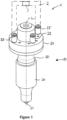
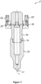
- the first embodiment of an ultrasonic processing system 1 shown in Figures 1 through 7 contains an ultrasonic vibrator 10 comprising an ultrasonic sonotrode 30 and an ultrasonic booster 50 extending along a longitudinal axis L. At its end directed away from the booster 50, the sonotrode has a working surface 31 for processing workpieces, for example for ultrasonic welding.
- a feeding flange 20 surrounds the booster 50 in a plane perpendicular to the longitudinal axis L and holds it in the area of a longitudinal vibrational node during intended operation.
- the feeding flange 20 comprises an inlet channel 22 for a first, gaseous cooling medium.
- the inlet channel 22 is arranged parallel to the longitudinal axis L.
- the feeding flange 20 further comprises a second inlet channel 55 through which a second, liquid cooling medium can be fed and a second outlet channel 56 through which the second cooling medium can be discharged.
- the system 1 also comprises an outer cooling section 2 fluidly connecting the second outlet channel 56 with the second inlet channel 55 and an outer cooling unit 3 for cooling the second cooling medium in the outer cooling section 2.
- the cooling unit 3 may be a Peltier cooling unit.
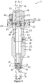
- the vibrator 10 comprises an enclosed cavity 32, 51 extending along the longitudinal axis L in both the booster 50 and the sonotrode 30.
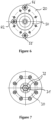
- the feeding flange 20 contains a first, inner ring channel 23 which surrounds the longitudinal axis L and fluidly connects the inlet channel 22 with medium inlets 52 which are formed as radial channels 52 in the booster 50.
- a gaseous cooling medium such as air can be fed into the cavity 32, 51.
- the air can be fed in at a pressure between 6 bar and 10 bar and at a temperature of slightly above 15 °C.
- the portion of the cavity 51 which extends in the booster 50 contains a first cylindrical section 59 which is directed towards a first connection end 57 of the booster 50 which may be connected to an ultrasonic converter which is not shown in Figure 2 .
- the first section 59 extends along the longitudinal axis L and has a first diameter d 1 .
- the portion of the cavity 51 extending in the booster 50 also contains a second cylindrical section 60 adjacent to the first cylindrical section 59 which is directed to a second connection end 58 of the booster 50.
- the booster 50 is releasably connected to the sonotrode 30 by a screw connection 70.
- the second cylindrical section 60 also extends along the longitudinal axis L and has a second diameter d 2 which is larger than the first diameter d 1 .
- the cavity 51 has a cross-section perpendicular to the longitudinal axis L which increases along the longitudinal axis L from the first connection end 57 to the second connection end 58.
- the outer perimeter of the booster 50 can be left almost constant along its length, thereby reducing bending induced by forces that may occur during operation of the system.
- the transition from the first cylindrical section 59 to the second cylindrical section 60 is located in the vicinity of a longitudinal vibrational node of the booster 50 during intended operation.
- the feeding flange 20 is also located at this transition.
- the system 1 further comprises a vortex generator 53 which is formed by a screw 62 and interior walls 63 delimiting a portion of the cavity 32 extending in the booster 50.
- a shaft portion 64 of the screw 62 is held in the first cylindrical section 59 of the cavity 51.
- a passage 61 is formed between an unthreaded part 66 of the shaft portion 64 and the interior walls 63.
- a threaded part of the shaft portion 64 facing away from a head portion 65 and the unthreaded part 66 sealingly engages with the first cylindrical section 59.
- the passage 61 extends parallel to the longitudinal axis L.
- the head portion 65 of the screw 62 is arranged in the second cylindrical section 60 of the cavity 51.
- the head portion 65 contains, on its side facing the shaft portion 65 and thus the first cylindrical section 59, several guiding surfaces 54.
- these guiding surfaces 54 deflect the cooling gas having entered through the medium inlets 52 and passed the passageway 61 into a swirl motion inside the cavity 32, 51 around the longitudinal axis L.
- the feeding flange 20 further comprises a cooling channel 21 through which a second cooling medium, preferably a cooling liquid such as water or methanol, can be guided.
- the cooling channel 21 is formed as a second, outer ring channel 21 which surrounds the longitudinal axis L and also the inner channel 23.
- a closed circuit is formed in which the cooling liquid enters through the second inlet channel 55, is guided through the ring channel 21, leaves through the second outlet channel 56 and is then cooled again in the outer cooling section 2 shown in Figure 1 .
- the cooling liquid flowing through the ring channel 21 cools the booster 50 and optionally an ultrasonic converter which is, however, not shown.
- the sonotrode 30 also contains a portion 32 of the enclosed cavity 32, 51.
- This portion 32 contains a first cylindrical section 36 which is directed towards the vortex generator 53, extends along the longitudinal axis L and has a first diameter D 1 and a second cylindrical section 37 adjacent to the first cylindrical section 36 which is directed away from the vortex generator 53, extends along the longitudinal axis L and has a second diameter D 2 which is smaller than the first diameter D 1 .
- D 2 ⁇ D 1 /2.
- the diameter d 2 of section 60 of the booster cavity 51 is equal to the diameter D 1 of section 37 of the sonotrode cavity 32.
- the vibrator 10 further contains six cooling channels 34 connected to the cavity 32.
- the cooling channels 34 end in first medium outlets 33 which are arranged in the vicinity of and around the working surface 31.
- the cooling channels 34 extend at an angle ⁇ of approximately 15° with respect to the longitudinal axis L.
- the first medium outlets 33 are arranged in a portion of the outer surface of the sonotrode 30 which is arranged at an angle ⁇ of approximately 75° with respect to the longitudinal axis L.
- a gaseous cooling medium such as air
- a gaseous cooling medium such as air
- This causes a swirl motion of the cooling medium around the axis L.
- a first portion of the cooling medium having flown through the radially inner area of the enclosed cavity 32, 51 and also a second portion of the cooling medium having flown through the radially outer area of the enclosed cavity 32, 51 then flows through the cooling channels 34 and are finally discharged through the first medium outlets 33.
- the sonotrode 30 additionally contains second medium outlets 35 connected to the enclosed cavity 32, 51 in such a way that at least a portion of the cooling medium having flown through a radially outer area of the enclosed cavity 32, 51 is guided to the second medium outlets 35.
- the second medium outlets 35 are arranged in a circumferential surface of the sonotrode 30, in the vicinity of a longitudinal vibrational node of the sonotrode 30 during intended operation. Directing this portion of the cooling gas away from the working surface 31 further enhances the cooling effect.
Landscapes
- Engineering & Computer Science (AREA)
- Mechanical Engineering (AREA)
- Physics & Mathematics (AREA)
- Thermal Sciences (AREA)
- Apparatuses For Generation Of Mechanical Vibrations (AREA)
- Turning (AREA)
- Physical Or Chemical Processes And Apparatus (AREA)
Claims (14)
- Ultraschallbearbeitungssystem (1) mit einem Ultraschallschwinger (10) mit einer Ultraschallsonotrode (30) mit mindestens einer Arbeitsfläche (31) zur Ultraschallbearbeitung mindestens eines Werkstücks, wobei der Schwinger (10) umfasst:- eine Längsachse (L),- einen eingeschlossenen Hohlraum (32, 51), der sich zumindest in der Sonotrode (30) entlang der Längsachse (L) erstreckt,- mindestens einen Medieneinlass (52), durch den ein Kühlmedium, insbesondere ein Kühlgas, in den Hohlraum (32, 51) eingeleitet werden kann,- mindestens einen Kühlkanal (34), der mit dem eingeschlossenen Hohlraum (32, 51) in Fluidverbindung steht und das Medium durch die Umgebung der Arbeitsfläche (31) leitet, so dass die Arbeitsfläche (31) durch das Kühlmedium gekühlt wird,- mindestens einen ersten Medienauslass (33), der mit dem Kühlkanal (34) in Fluidverbindung steht,dadurch gekennzeichnet, dass
der Schwinger (10) ferner mindestens einen Wirbelgenerator (53) umfasst, der so ausgebildet und zwischen dem Medieneinlass (52) und dem Hohlraum (32, 51) angeordnet ist, dass eine Wirbelbewegung des Mediums innerhalb des Hohlraums (32, 51) um die Längsachse (L) erzeugt werden kann. - Ultraschallbearbeitungssystem (1) nach Anspruch 1,
wobei der Schwinger (10) ferner einen Booster (50) umfasst, der mit der Sonotrode (30) verbunden ist und der den Medieneinlass (52) und den Wirbelgenerator (53) enthält, wobei sich der eingeschlossene Hohlraum (32, 51) sowohl in der Sonotrode (30) als auch im Booster (50) erstreckt. - Ultraschallbearbeitungssystem (1) nach einem der vorhergehenden Ansprüche,
wobei der Wirbelgenerator (53) mindestens eine, vorzugsweise mehrere Leitflächen (54) enthält, die dazu ausgebildet und angeordnet sind, das durch den Medieneinlass (52) eingetretene Kühlmedium (52) im Inneren des Hohlraums (32, 51) in eine Wirbelbewegung um die Längsachse (L) zu lenken. - Ultraschallbearbeitungssystem (1) nach einem der vorhergehenden Ansprüche,
wobei der eingeschlossene Hohlraum (32, 51), insbesondere ein Teil des Hohlraums (32), der sich in der Sonotrode (30) erstreckt, enthält- einen ersten zylindrischen Abschnitt (36), der auf den Wirbelgenerator (53) hin gerichtet ist, sich entlang der Längsachse (L) erstreckt und einen ersten Durchmesser (D1) aufweist, und- einen an den ersten zylindrischen Abschnitt (36) angrenzenden zweiten zylindrischen Abschnitt (37), der vom Wirbelgenerator (53) weg gerichtet ist, sich entlang der Längsachse (L) erstreckt und einen zweiten Durchmesser (D2) aufweist, der kleiner ist als der erste Durchmesser (D1), wobei insbesondere D2 < D1/2. - Ultraschallbearbeitungssystem (1) nach einem der vorhergehenden Ansprüche,
wobei der erste Medienauslass (33) in der Nähe der Arbeitsfläche (31) angeordnet ist. - Ultraschallbehandlungssystem (1) nach Anspruch 5,
wobei der erste Medienauslass (33) in einem Abschnitt der Aussenfläche der Sonotrode (30) angeordnet ist, der in einem Winkel (β) in Bezug auf die Längsachse (L) angeordnet ist, wobei der Winkel (β) vorzugsweise im Bereich von 60° bis 80° liegt. - Ultraschallbearbeitungssystem (1) nach einem der vorhergehenden Ansprüche,
wobei sich der Kühlkanal (34) in einem Winkel (α) in Bezug auf die Längsachse (L) erstreckt, wobei der Winkel (α) vorzugsweise weniger als 60° und besonders bevorzugt im Bereich von 7° bis 15° liegt. - Ultraschallbearbeitungssystem (1) nach einem der vorhergehenden Ansprüche,
wobei der Schwinger (10), insbesondere die Sonotrode (30), ferner mindestens einen zweiten Medienauslass (35) aufweist, der mit dem eingeschlossenen Hohlraum (32, 51) derart fluidisch verbunden ist, dass mindestens ein Teil des Kühlmediums, das einen radial äusseren Bereich des eingeschlossenen Hohlraums (32, 51) durchströmt hat, zum zweiten Medienauslass (35) geleitet wird, wobei der zweite Medienauslass (35) weiter von der Arbeitsfläche (31) entfernt ist als der erste Medienauslass (33). - Ultraschall-Booster (50), insbesondere zur Verwendung in einem Ultraschallbearbeitungssystem (1) nach einem der vorhergehenden Ansprüche, wobei der Booster (50) umfasst:- eine Längsachse (L),- einen Hohlraum (51), der sich in dem Booster (30) erstreckt,- Verbindungsmittel (70), insbesondere Schraubverbindungsmittel (70), zum Verbinden des Boosters (50) mit einer einen Hohlraum (32) aufweisenden Ultraschallsonotrode (30), derart, dass der Hohlraum (51) des Boosters (50) und der Hohlraum (32) der Sonotrode (30) einen eingeschlossenen Hohlraum (32, 51) des verbundenen Boosters (50) und der Sonotrode (30) bilden,- mindestens einen Medieneinlass (52), durch den ein Kühlmedium in den Hohlraum (51) des Boosters (50) eingeleitet werden kann,- mindestens einen Wirbelgenerator (53), der so ausgebildet und zwischen dem Medieneinlass (52) und dem eingeschlossenen Hohlraum (32, 51) angeordnet ist, dass eine Wirbelbewegung des Mediums innerhalb des eingeschlossenen Hohlraums (32, 51) um die Längsachse (L) erzeugt werden kann.
- Ultraschall-Booster (50) nach Anspruch 9,
wobei der Wirbelgenerator (53) mindestens eine, vorzugsweise mehrere Leitflächen (54) enthält, die dazu ausgebildet und angeordnet sind, das durch den Medieneinlass (52) eingetretene Kühlmedium (52) in eine Wirbelbewegung innerhalb des Hohlraums (51) um die Längsachse (L) zu lenken. - Ultraschall-Booster (50) nach einem der Ansprüche 9 und 10, ferner umfassend:- ein erstes Anschlussende (57), an dem der Booster (50) mit einem Ultraschallwandler verbunden werden kann,- ein zweites Anschlussende (58), das dem ersten Anschlussende (57) in Bezug auf die Längsachse (L) gegenüberliegt, wobei der Booster (50) am zweiten Anschlussende (58) durch Verbindungsmittel (70), insbesondere Schraubverbindungsmittel (70), mit einer Ultraschallsonotrode (30) verbindbar ist,wobei der Hohlraum (51) einen Querschnitt senkrecht zur Längsachse (L) aufweist, der zumindest in einem Abschnitt entlang der Längsachse (L) vom ersten Anschlussende (57) zum zweiten Anschlussende (58) zunimmt.
- Ultraschall-Booster (50) nach Anspruch 11,
wobei der Hohlraum (51) enthält:- einen ersten zylindrischen Abschnitt (59), der auf das erste Anschlussende (57) hin gerichtet ist, sich entlang der Längsachse (L) erstreckt und einen ersten Durchmesser (d1) aufweist, und- einen zweiten zylindrischen Abschnitt (60), der an den ersten zylindrischen Abschnitt (59) angrenzt, zum zweiten Anschlussende (58) hin gerichtet ist, sich entlang der Längsachse (L) erstreckt und einen zweiten Durchmesser (d2) aufweist, der grösser ist als der erste Durchmesser (d1). - Verfahren zur Ultraschallbearbeitung mindestens eines Werkstücks unter Verwendung eines Ultraschallbearbeitungssystems (1) nach einem der Ansprüche 1 bis 8, wobei das Verfahren die folgenden Schritte umfasst:- Ultraschallbearbeitung des Werkstücks durch die Arbeitsfläche (31) der Sonotrode (30),- Zuführen eines Kühlmediums durch den Medieneinlass (52) in den eingeschlossenen Hohlraum (32, 51), wodurch mit dem Wirbelgenerator (53) eine Wirbelbewegung des Mediums innerhalb des eingeschlossenen Hohlraums (32, 51) um die Längsachse (L) erzeugt wird, und Kühlen der Arbeitsfläche (31) durch das aus dem Medienauslass (33) ausströmende Medium.
- Verfahren nach Anspruch 13 zur Ultraschallbearbeitung einer Vielzahl von Werkstücken, umfassend die Schrittea) Ultraschallbearbeitung eines ersten Werkstücks durch die Arbeitsfläche (31) der Sonotrode (30),b) Zuführen eines Kühlmediums durch den Medieneinlass (52) in den eingeschlossenen Hohlraum (32, 51), wodurch eine Wirbelbewegung des Mediums innerhalb des eingeschlossenen Hohlraums (32, 51) um die Längsachse (L) erzeugt wird, und Kühlen der Arbeitsfläche (31) durch das aus dem Medienauslass (33) ausströmende Medium,c) Ultraschallbearbeitung eines zweiten Werkstücks durch die Arbeitsfläche (31) der Sonotrode (30),d) optionales Wiederholen der Schritte b) und c) ein oder mehrere Male.
Applications Claiming Priority (1)
| Application Number | Priority Date | Filing Date | Title |
|---|---|---|---|
| PCT/EP2017/053117 WO2018145769A1 (en) | 2017-02-13 | 2017-02-13 | Ultrasonic processing system, booster and method |
Publications (2)
| Publication Number | Publication Date |
|---|---|
| EP3580045A1 EP3580045A1 (de) | 2019-12-18 |
| EP3580045B1 true EP3580045B1 (de) | 2023-08-30 |
Family
ID=58057111
Family Applications (1)
| Application Number | Title | Priority Date | Filing Date |
|---|---|---|---|
| EP17705830.2A Active EP3580045B1 (de) | 2017-02-13 | 2017-02-13 | Ultraschall-verarbeitungssystem, verstärker und verfahren |
Country Status (4)
| Country | Link |
|---|---|
| US (1) | US11292209B2 (de) |
| EP (1) | EP3580045B1 (de) |
| CN (1) | CN110267799B (de) |
| WO (1) | WO2018145769A1 (de) |
Families Citing this family (8)
| Publication number | Priority date | Publication date | Assignee | Title |
|---|---|---|---|---|
| CN113231729B (zh) * | 2021-03-31 | 2023-03-14 | 广东富强科技股份有限公司 | 一种r轴优化的超声波焊接装置 |
| CN113790975B (zh) * | 2021-09-14 | 2022-08-23 | 吉林大学 | 超声变幅杆组件、超声疲劳加载测试装置及测试方法 |
| EP4265400B1 (de) * | 2022-04-18 | 2025-09-03 | The Procter & Gamble Company | Kühlverfahren zur ultraschallformung und verbindung von polymerbahnen |
| EP4265399B1 (de) | 2022-04-18 | 2026-04-01 | The Procter & Gamble Company | Kühlverfahren zur ultraschallformung und verbindung von polymerbahnen |
| CN116871548B (zh) * | 2023-08-22 | 2025-09-09 | 大连海事大学 | 一种涡流内冷和超声振动复合加工装置 |
| KR102786855B1 (ko) * | 2024-04-11 | 2025-03-26 | 주식회사 에이치와이티씨 | 토셔널 초음파 진동 변환기 |
| KR102755244B1 (ko) * | 2024-07-08 | 2025-01-21 | 주식회사 에이치와이티씨 | 초음파 복합 진동 변환기 |
| EP4717392A1 (de) | 2024-09-27 | 2026-04-01 | Telsonic Holding AG | Verfahren zur zerstörungsfreien prüfung einer verbindung zwischen zwei bauteilen, verfahren zum erzeugen einer schweissverbindung zwischen wenigstens zwei bauteilen, schweissvorrichtung, computerprogrammprodukt, computerlesbares speichermedium, verfahren zum trainieren eines maschinellen lernmodells zum vorhersagen einer schweissqualität sowie maschinenlernmodell zum vorhersagen einer schweissqualität |
Citations (2)
| Publication number | Priority date | Publication date | Assignee | Title |
|---|---|---|---|---|
| US20110120064A1 (en) * | 2009-11-25 | 2011-05-26 | Uhlmann Pac-Systeme Gmbh & Co. Kg | Sealing station |
| WO2017001255A2 (de) * | 2015-06-30 | 2017-01-05 | Telsonic Holding Ag | Vorrichtung zum verschweissen von bauteilen mittels ultraschalls |
Family Cites Families (21)
| Publication number | Priority date | Publication date | Assignee | Title |
|---|---|---|---|---|
| US3529660A (en) | 1968-11-20 | 1970-09-22 | Branson Instr | Solid horn with cooling means |
| CS193252B1 (en) | 1977-07-01 | 1979-10-31 | Jiri Gurnak | Facility for adjusting and cooling the ultrasound radiator |
| DE4206584C2 (de) | 1992-03-03 | 1994-03-10 | Fraunhofer Ges Forschung | Vorrichtung und Verfahren zum Verbinden zweier Bauteile mittels Ultraschall |
| US6422817B1 (en) * | 2000-01-13 | 2002-07-23 | General Electric Company | Cooling circuit for and method of cooling a gas turbine bucket |
| US6691909B2 (en) | 2001-10-10 | 2004-02-17 | Ford Global Technologies, Llc | Sonotrode for ultrasonic welding apparatus |
| DE10151992B8 (de) | 2001-10-22 | 2004-12-16 | Kunststoff-Zentrum in Leipzig gemeinnützige Gesellschaft mbH | Kühlelement zum Einsatz in schwingenden Systemen |
| US20030219602A1 (en) * | 2002-03-28 | 2003-11-27 | Kagan Val A. | Ultrasonic joining of thermoplastic parts |
| DE10250741B4 (de) | 2002-10-31 | 2004-08-26 | Kunststoff-Zentrum in Leipzig gemeinnützige Gesellschaft mbH | Beheiztes Schwingwerkzeug zum Einsatz in schwingenden Systemen |
| US7703698B2 (en) * | 2006-09-08 | 2010-04-27 | Kimberly-Clark Worldwide, Inc. | Ultrasonic liquid treatment chamber and continuous flow mixing system |
| US9167845B2 (en) * | 2006-09-08 | 2015-10-27 | Creative Resonance, Inc. | Apparatus, method and product for ultrasonic extrusion of a flowable substrate |
| US20100147466A1 (en) * | 2007-03-02 | 2010-06-17 | Compania Espanola De Ulltrasonidos, Sa | Ultrasonic head and transducer for ultrasonic soldering of plastics |
| DE202008007271U1 (de) | 2008-05-27 | 2008-07-31 | Stemke, Gudrun | Sonotrode |
| DE102008029769A1 (de) * | 2008-06-25 | 2009-12-31 | Sonotronic Nagel Gmbh | Sonotrodenwerkzeug mit Kühleinrichtung |
| DE202008008426U1 (de) | 2008-06-25 | 2008-11-06 | Sonotronic Nagel Gmbh | Sonotrodenwerkzeug mit Kühleinrichtung |
| US20150062813A1 (en) * | 2012-04-03 | 2015-03-05 | Siemens Aktiengesellschaft | Cooling device |
| CN202914402U (zh) * | 2012-07-24 | 2013-05-01 | 杭州宇佳化工设备有限公司 | 一种压缩机水冷式高压填料 |
| CN202781832U (zh) * | 2012-08-08 | 2013-03-13 | 东莞市长江超声波机有限公司 | 超声波焊头的冷却结构 |
| DE102013215106A1 (de) | 2013-08-01 | 2015-02-05 | PP-Tech GmbH | Sonotrodenwerkzeug mit integrierter Kühleinrichtung |
| KR101509385B1 (ko) * | 2014-01-16 | 2015-04-07 | 두산중공업 주식회사 | 스월링 냉각 채널을 구비한 터빈 블레이드 및 그 냉각 방법 |
| CN104201933B (zh) * | 2014-09-03 | 2017-01-25 | 上海交通大学 | 一种超声电机液冷散热结构 |
| ES1163609Y (es) | 2016-07-12 | 2016-11-17 | Compania Espanola De Ultrasonidos S A | Sonotrodo con sistema de refrigeracion |
-
2017
- 2017-02-13 US US16/471,871 patent/US11292209B2/en active Active
- 2017-02-13 EP EP17705830.2A patent/EP3580045B1/de active Active
- 2017-02-13 WO PCT/EP2017/053117 patent/WO2018145769A1/en not_active Ceased
- 2017-02-13 CN CN201780086132.2A patent/CN110267799B/zh active Active
Patent Citations (2)
| Publication number | Priority date | Publication date | Assignee | Title |
|---|---|---|---|---|
| US20110120064A1 (en) * | 2009-11-25 | 2011-05-26 | Uhlmann Pac-Systeme Gmbh & Co. Kg | Sealing station |
| WO2017001255A2 (de) * | 2015-06-30 | 2017-01-05 | Telsonic Holding Ag | Vorrichtung zum verschweissen von bauteilen mittels ultraschalls |
Also Published As
| Publication number | Publication date |
|---|---|
| CN110267799B (zh) | 2023-08-08 |
| US11292209B2 (en) | 2022-04-05 |
| US20200086586A1 (en) | 2020-03-19 |
| EP3580045A1 (de) | 2019-12-18 |
| WO2018145769A1 (en) | 2018-08-16 |
| CN110267799A (zh) | 2019-09-20 |
Similar Documents
| Publication | Publication Date | Title |
|---|---|---|
| US11292209B2 (en) | Ultrasonic processing system, booster and method | |
| US7823487B2 (en) | Cutting tool | |
| US8734144B2 (en) | Device for selectively depositing molten plastic materials | |
| US8004158B2 (en) | Method and device for cooling ultrasonic transducers | |
| KR102279676B1 (ko) | 레이저 가공용 노즐 및 이를 이용한 레이저 가공방법 | |
| JP2018531799A (ja) | レーザ部品の水冷のためのレーザ加工ヘッド用の熱調整装置 | |
| US10792681B2 (en) | Nozzle for discharging compressed air | |
| KR20180129930A (ko) | 노즐들 및 다른 소모품들을 포함하는 플라즈마 아크 절단 시스템 및 관련된 작동 방법들 | |
| JP2010519073A (ja) | 射出成形用ノズル | |
| US9080793B2 (en) | Method and apparatus in connection with a vortex tube process | |
| CN108602136A (zh) | 刀架 | |
| US4545751A (en) | Apparatus for molding of plastic tubing | |
| CN114952033B (zh) | 一种新型激光切割喷嘴及具有该喷嘴的激光切割装置 | |
| JPS59104604A (ja) | レ−ザにおいて特に有用な冷却ミラ− | |
| JP2020040126A (ja) | 機械加工ヘッド及び機械加工装置 | |
| CN104620374A (zh) | 冷却设备 | |
| US9882339B2 (en) | Laser oscillation device having laser medium circulating tube | |
| CN119457464A (zh) | 喷嘴冷却元件和具有喷嘴冷却元件的激光加工设备 | |
| EP4706868A1 (de) | Laserschneiddüse | |
| JP2001018265A (ja) | 樹脂製品のハンドリング装置および方法 | |
| RU2192338C2 (ru) | Плазмотрон для воздушно-плазменной резки | |
| JP2008264948A (ja) | 切削工具 | |
| CN120095428A (zh) | 超声波焊接系统用冷却装置、超声波焊接装置以及运行超声波焊接装置的方法 | |
| JPH09232652A (ja) | 固体レーザ装置 |
Legal Events
| Date | Code | Title | Description |
|---|---|---|---|
| STAA | Information on the status of an ep patent application or granted ep patent |
Free format text: STATUS: UNKNOWN |
|
| STAA | Information on the status of an ep patent application or granted ep patent |
Free format text: STATUS: THE INTERNATIONAL PUBLICATION HAS BEEN MADE |
|
| PUAI | Public reference made under article 153(3) epc to a published international application that has entered the european phase |
Free format text: ORIGINAL CODE: 0009012 |
|
| STAA | Information on the status of an ep patent application or granted ep patent |
Free format text: STATUS: REQUEST FOR EXAMINATION WAS MADE |
|
| 17P | Request for examination filed |
Effective date: 20190701 |
|
| AK | Designated contracting states |
Kind code of ref document: A1 Designated state(s): AL AT BE BG CH CY CZ DE DK EE ES FI FR GB GR HR HU IE IS IT LI LT LU LV MC MK MT NL NO PL PT RO RS SE SI SK SM TR |
|
| AX | Request for extension of the european patent |
Extension state: BA ME |
|
| DAV | Request for validation of the european patent (deleted) | ||
| DAX | Request for extension of the european patent (deleted) | ||
| STAA | Information on the status of an ep patent application or granted ep patent |
Free format text: STATUS: EXAMINATION IS IN PROGRESS |
|
| 17Q | First examination report despatched |
Effective date: 20211210 |
|
| RIC1 | Information provided on ipc code assigned before grant |
Ipc: B23K 103/00 20060101ALN20230306BHEP Ipc: B23K 20/10 20060101ALI20230306BHEP Ipc: B23K 1/06 20060101ALI20230306BHEP Ipc: B29C 65/08 20060101AFI20230306BHEP |
|
| GRAP | Despatch of communication of intention to grant a patent |
Free format text: ORIGINAL CODE: EPIDOSNIGR1 |
|
| STAA | Information on the status of an ep patent application or granted ep patent |
Free format text: STATUS: GRANT OF PATENT IS INTENDED |
|
| INTG | Intention to grant announced |
Effective date: 20230417 |
|
| GRAS | Grant fee paid |
Free format text: ORIGINAL CODE: EPIDOSNIGR3 |
|
| GRAA | (expected) grant |
Free format text: ORIGINAL CODE: 0009210 |
|
| STAA | Information on the status of an ep patent application or granted ep patent |
Free format text: STATUS: THE PATENT HAS BEEN GRANTED |
|
| AK | Designated contracting states |
Kind code of ref document: B1 Designated state(s): AL AT BE BG CH CY CZ DE DK EE ES FI FR GB GR HR HU IE IS IT LI LT LU LV MC MK MT NL NO PL PT RO RS SE SI SK SM TR |
|
| REG | Reference to a national code |
Ref country code: GB Ref legal event code: FG4D |
|
| REG | Reference to a national code |
Ref country code: CH Ref legal event code: EP |
|
| REG | Reference to a national code |
Ref country code: DE Ref legal event code: R096 Ref document number: 602017073357 Country of ref document: DE |
|
| REG | Reference to a national code |
Ref country code: IE Ref legal event code: FG4D |
|
| REG | Reference to a national code |
Ref country code: LT Ref legal event code: MG9D |
|
| REG | Reference to a national code |
Ref country code: NL Ref legal event code: MP Effective date: 20230830 |
|
| REG | Reference to a national code |
Ref country code: AT Ref legal event code: MK05 Ref document number: 1604904 Country of ref document: AT Kind code of ref document: T Effective date: 20230830 |
|
| PG25 | Lapsed in a contracting state [announced via postgrant information from national office to epo] |
Ref country code: GR Free format text: LAPSE BECAUSE OF FAILURE TO SUBMIT A TRANSLATION OF THE DESCRIPTION OR TO PAY THE FEE WITHIN THE PRESCRIBED TIME-LIMIT Effective date: 20231201 |
|
| PG25 | Lapsed in a contracting state [announced via postgrant information from national office to epo] |
Ref country code: IS Free format text: LAPSE BECAUSE OF FAILURE TO SUBMIT A TRANSLATION OF THE DESCRIPTION OR TO PAY THE FEE WITHIN THE PRESCRIBED TIME-LIMIT Effective date: 20231230 |
|
| PG25 | Lapsed in a contracting state [announced via postgrant information from national office to epo] |
Ref country code: SE Free format text: LAPSE BECAUSE OF FAILURE TO SUBMIT A TRANSLATION OF THE DESCRIPTION OR TO PAY THE FEE WITHIN THE PRESCRIBED TIME-LIMIT Effective date: 20230830 Ref country code: RS Free format text: LAPSE BECAUSE OF FAILURE TO SUBMIT A TRANSLATION OF THE DESCRIPTION OR TO PAY THE FEE WITHIN THE PRESCRIBED TIME-LIMIT Effective date: 20230830 Ref country code: NO Free format text: LAPSE BECAUSE OF FAILURE TO SUBMIT A TRANSLATION OF THE DESCRIPTION OR TO PAY THE FEE WITHIN THE PRESCRIBED TIME-LIMIT Effective date: 20231130 Ref country code: LV Free format text: LAPSE BECAUSE OF FAILURE TO SUBMIT A TRANSLATION OF THE DESCRIPTION OR TO PAY THE FEE WITHIN THE PRESCRIBED TIME-LIMIT Effective date: 20230830 Ref country code: LT Free format text: LAPSE BECAUSE OF FAILURE TO SUBMIT A TRANSLATION OF THE DESCRIPTION OR TO PAY THE FEE WITHIN THE PRESCRIBED TIME-LIMIT Effective date: 20230830 Ref country code: IS Free format text: LAPSE BECAUSE OF FAILURE TO SUBMIT A TRANSLATION OF THE DESCRIPTION OR TO PAY THE FEE WITHIN THE PRESCRIBED TIME-LIMIT Effective date: 20231230 Ref country code: HR Free format text: LAPSE BECAUSE OF FAILURE TO SUBMIT A TRANSLATION OF THE DESCRIPTION OR TO PAY THE FEE WITHIN THE PRESCRIBED TIME-LIMIT Effective date: 20230830 Ref country code: GR Free format text: LAPSE BECAUSE OF FAILURE TO SUBMIT A TRANSLATION OF THE DESCRIPTION OR TO PAY THE FEE WITHIN THE PRESCRIBED TIME-LIMIT Effective date: 20231201 Ref country code: FI Free format text: LAPSE BECAUSE OF FAILURE TO SUBMIT A TRANSLATION OF THE DESCRIPTION OR TO PAY THE FEE WITHIN THE PRESCRIBED TIME-LIMIT Effective date: 20230830 Ref country code: AT Free format text: LAPSE BECAUSE OF FAILURE TO SUBMIT A TRANSLATION OF THE DESCRIPTION OR TO PAY THE FEE WITHIN THE PRESCRIBED TIME-LIMIT Effective date: 20230830 |
|
| PG25 | Lapsed in a contracting state [announced via postgrant information from national office to epo] |
Ref country code: PL Free format text: LAPSE BECAUSE OF FAILURE TO SUBMIT A TRANSLATION OF THE DESCRIPTION OR TO PAY THE FEE WITHIN THE PRESCRIBED TIME-LIMIT Effective date: 20230830 Ref country code: NL Free format text: LAPSE BECAUSE OF FAILURE TO SUBMIT A TRANSLATION OF THE DESCRIPTION OR TO PAY THE FEE WITHIN THE PRESCRIBED TIME-LIMIT Effective date: 20230830 |
|
| PG25 | Lapsed in a contracting state [announced via postgrant information from national office to epo] |
Ref country code: ES Free format text: LAPSE BECAUSE OF FAILURE TO SUBMIT A TRANSLATION OF THE DESCRIPTION OR TO PAY THE FEE WITHIN THE PRESCRIBED TIME-LIMIT Effective date: 20230830 |
|
| PG25 | Lapsed in a contracting state [announced via postgrant information from national office to epo] |
Ref country code: SM Free format text: LAPSE BECAUSE OF FAILURE TO SUBMIT A TRANSLATION OF THE DESCRIPTION OR TO PAY THE FEE WITHIN THE PRESCRIBED TIME-LIMIT Effective date: 20230830 Ref country code: RO Free format text: LAPSE BECAUSE OF FAILURE TO SUBMIT A TRANSLATION OF THE DESCRIPTION OR TO PAY THE FEE WITHIN THE PRESCRIBED TIME-LIMIT Effective date: 20230830 Ref country code: ES Free format text: LAPSE BECAUSE OF FAILURE TO SUBMIT A TRANSLATION OF THE DESCRIPTION OR TO PAY THE FEE WITHIN THE PRESCRIBED TIME-LIMIT Effective date: 20230830 Ref country code: EE Free format text: LAPSE BECAUSE OF FAILURE TO SUBMIT A TRANSLATION OF THE DESCRIPTION OR TO PAY THE FEE WITHIN THE PRESCRIBED TIME-LIMIT Effective date: 20230830 Ref country code: DK Free format text: LAPSE BECAUSE OF FAILURE TO SUBMIT A TRANSLATION OF THE DESCRIPTION OR TO PAY THE FEE WITHIN THE PRESCRIBED TIME-LIMIT Effective date: 20230830 Ref country code: CZ Free format text: LAPSE BECAUSE OF FAILURE TO SUBMIT A TRANSLATION OF THE DESCRIPTION OR TO PAY THE FEE WITHIN THE PRESCRIBED TIME-LIMIT Effective date: 20230830 Ref country code: SK Free format text: LAPSE BECAUSE OF FAILURE TO SUBMIT A TRANSLATION OF THE DESCRIPTION OR TO PAY THE FEE WITHIN THE PRESCRIBED TIME-LIMIT Effective date: 20230830 Ref country code: PT Free format text: LAPSE BECAUSE OF FAILURE TO SUBMIT A TRANSLATION OF THE DESCRIPTION OR TO PAY THE FEE WITHIN THE PRESCRIBED TIME-LIMIT Effective date: 20240102 |
|
| PG25 | Lapsed in a contracting state [announced via postgrant information from national office to epo] |
Ref country code: IT Free format text: LAPSE BECAUSE OF FAILURE TO SUBMIT A TRANSLATION OF THE DESCRIPTION OR TO PAY THE FEE WITHIN THE PRESCRIBED TIME-LIMIT Effective date: 20230830 |
|
| REG | Reference to a national code |
Ref country code: DE Ref legal event code: R097 Ref document number: 602017073357 Country of ref document: DE |
|
| PLBE | No opposition filed within time limit |
Free format text: ORIGINAL CODE: 0009261 |
|
| STAA | Information on the status of an ep patent application or granted ep patent |
Free format text: STATUS: NO OPPOSITION FILED WITHIN TIME LIMIT |
|
| PG25 | Lapsed in a contracting state [announced via postgrant information from national office to epo] |
Ref country code: SI Free format text: LAPSE BECAUSE OF FAILURE TO SUBMIT A TRANSLATION OF THE DESCRIPTION OR TO PAY THE FEE WITHIN THE PRESCRIBED TIME-LIMIT Effective date: 20230830 |
|
| 26N | No opposition filed |
Effective date: 20240603 |
|
| PG25 | Lapsed in a contracting state [announced via postgrant information from national office to epo] |
Ref country code: MC Free format text: LAPSE BECAUSE OF FAILURE TO SUBMIT A TRANSLATION OF THE DESCRIPTION OR TO PAY THE FEE WITHIN THE PRESCRIBED TIME-LIMIT Effective date: 20230830 |
|
| PG25 | Lapsed in a contracting state [announced via postgrant information from national office to epo] |
Ref country code: LU Free format text: LAPSE BECAUSE OF NON-PAYMENT OF DUE FEES Effective date: 20240213 |
|
| GBPC | Gb: european patent ceased through non-payment of renewal fee |
Effective date: 20240213 |
|
| PG25 | Lapsed in a contracting state [announced via postgrant information from national office to epo] |
Ref country code: LU Free format text: LAPSE BECAUSE OF NON-PAYMENT OF DUE FEES Effective date: 20240213 |
|
| PG25 | Lapsed in a contracting state [announced via postgrant information from national office to epo] |
Ref country code: BG Free format text: LAPSE BECAUSE OF FAILURE TO SUBMIT A TRANSLATION OF THE DESCRIPTION OR TO PAY THE FEE WITHIN THE PRESCRIBED TIME-LIMIT Effective date: 20230830 |
|
| PG25 | Lapsed in a contracting state [announced via postgrant information from national office to epo] |
Ref country code: BG Free format text: LAPSE BECAUSE OF FAILURE TO SUBMIT A TRANSLATION OF THE DESCRIPTION OR TO PAY THE FEE WITHIN THE PRESCRIBED TIME-LIMIT Effective date: 20230830 |
|
| REG | Reference to a national code |
Ref country code: BE Ref legal event code: MM Effective date: 20240229 |
|
| PG25 | Lapsed in a contracting state [announced via postgrant information from national office to epo] |
Ref country code: BE Free format text: LAPSE BECAUSE OF NON-PAYMENT OF DUE FEES Effective date: 20240229 |
|
| PG25 | Lapsed in a contracting state [announced via postgrant information from national office to epo] |
Ref country code: GB Free format text: LAPSE BECAUSE OF NON-PAYMENT OF DUE FEES Effective date: 20240213 |
|
| PG25 | Lapsed in a contracting state [announced via postgrant information from national office to epo] |
Ref country code: FR Free format text: LAPSE BECAUSE OF NON-PAYMENT OF DUE FEES Effective date: 20240229 |
|
| PG25 | Lapsed in a contracting state [announced via postgrant information from national office to epo] |
Ref country code: IE Free format text: LAPSE BECAUSE OF NON-PAYMENT OF DUE FEES Effective date: 20240213 |
|
| PG25 | Lapsed in a contracting state [announced via postgrant information from national office to epo] |
Ref country code: IE Free format text: LAPSE BECAUSE OF NON-PAYMENT OF DUE FEES Effective date: 20240213 Ref country code: GB Free format text: LAPSE BECAUSE OF NON-PAYMENT OF DUE FEES Effective date: 20240213 Ref country code: FR Free format text: LAPSE BECAUSE OF NON-PAYMENT OF DUE FEES Effective date: 20240229 Ref country code: BE Free format text: LAPSE BECAUSE OF NON-PAYMENT OF DUE FEES Effective date: 20240229 |
|
| PG25 | Lapsed in a contracting state [announced via postgrant information from national office to epo] |
Ref country code: CY Free format text: LAPSE BECAUSE OF FAILURE TO SUBMIT A TRANSLATION OF THE DESCRIPTION OR TO PAY THE FEE WITHIN THE PRESCRIBED TIME-LIMIT; INVALID AB INITIO Effective date: 20170213 |
|
| PG25 | Lapsed in a contracting state [announced via postgrant information from national office to epo] |
Ref country code: HU Free format text: LAPSE BECAUSE OF FAILURE TO SUBMIT A TRANSLATION OF THE DESCRIPTION OR TO PAY THE FEE WITHIN THE PRESCRIBED TIME-LIMIT; INVALID AB INITIO Effective date: 20170213 |
|
| PG25 | Lapsed in a contracting state [announced via postgrant information from national office to epo] |
Ref country code: TR Free format text: LAPSE BECAUSE OF FAILURE TO SUBMIT A TRANSLATION OF THE DESCRIPTION OR TO PAY THE FEE WITHIN THE PRESCRIBED TIME-LIMIT Effective date: 20230830 |
|
| REG | Reference to a national code |
Ref country code: CH Ref legal event code: U11 Free format text: ST27 STATUS EVENT CODE: U-0-0-U10-U11 (AS PROVIDED BY THE NATIONAL OFFICE) Effective date: 20260301 |
|
| PGFP | Annual fee paid to national office [announced via postgrant information from national office to epo] |
Ref country code: DE Payment date: 20251216 Year of fee payment: 10 |
|
| PGFP | Annual fee paid to national office [announced via postgrant information from national office to epo] |
Ref country code: CH Payment date: 20260301 Year of fee payment: 10 |