EP3580087B1 - Siege pour vehicule avec dossier basculant - Google Patents
Siege pour vehicule avec dossier basculant Download PDFInfo
- Publication number
- EP3580087B1 EP3580087B1 EP18706798.8A EP18706798A EP3580087B1 EP 3580087 B1 EP3580087 B1 EP 3580087B1 EP 18706798 A EP18706798 A EP 18706798A EP 3580087 B1 EP3580087 B1 EP 3580087B1
- Authority
- EP
- European Patent Office
- Prior art keywords
- upright
- seat
- fixed frame
- seat according
- fixed
- Prior art date
- Legal status (The legal status is an assumption and is not a legal conclusion. Google has not performed a legal analysis and makes no representation as to the accuracy of the status listed.)
- Active
Links
Images






Classifications
-
- B—PERFORMING OPERATIONS; TRANSPORTING
- B60—VEHICLES IN GENERAL
- B60N—SEATS SPECIALLY ADAPTED FOR VEHICLES; VEHICLE PASSENGER ACCOMMODATION NOT OTHERWISE PROVIDED FOR
- B60N2/00—Seats specially adapted for vehicles; Arrangement or mounting of seats in vehicles
- B60N2/24—Seats specially adapted for vehicles; Arrangement or mounting of seats in vehicles for particular purposes or particular vehicles
- B60N2/42—Seats specially adapted for vehicles; Arrangement or mounting of seats in vehicles for particular purposes or particular vehicles the seat constructed to protect the occupant from the effect of abnormal g-forces, e.g. crash or safety seats
- B60N2/427—Seats or parts thereof displaced during a crash
- B60N2/42727—Seats or parts thereof displaced during a crash involving substantially rigid displacement
- B60N2/42745—Seats or parts thereof displaced during a crash involving substantially rigid displacement of the back-rest
-
- B—PERFORMING OPERATIONS; TRANSPORTING
- B60—VEHICLES IN GENERAL
- B60N—SEATS SPECIALLY ADAPTED FOR VEHICLES; VEHICLE PASSENGER ACCOMMODATION NOT OTHERWISE PROVIDED FOR
- B60N2/00—Seats specially adapted for vehicles; Arrangement or mounting of seats in vehicles
- B60N2/24—Seats specially adapted for vehicles; Arrangement or mounting of seats in vehicles for particular purposes or particular vehicles
- B60N2/42—Seats specially adapted for vehicles; Arrangement or mounting of seats in vehicles for particular purposes or particular vehicles the seat constructed to protect the occupant from the effect of abnormal g-forces, e.g. crash or safety seats
- B60N2/427—Seats or parts thereof displaced during a crash
- B60N2/42709—Seats or parts thereof displaced during a crash involving residual deformation or fracture of the structure
-
- B—PERFORMING OPERATIONS; TRANSPORTING
- B60—VEHICLES IN GENERAL
- B60N—SEATS SPECIALLY ADAPTED FOR VEHICLES; VEHICLE PASSENGER ACCOMMODATION NOT OTHERWISE PROVIDED FOR
- B60N2/00—Seats specially adapted for vehicles; Arrangement or mounting of seats in vehicles
- B60N2/90—Details or parts not otherwise provided for
- B60N2/919—Positioning and locking mechanisms
- B60N2/933—Positioning and locking mechanisms rotatable
-
- F—MECHANICAL ENGINEERING; LIGHTING; HEATING; WEAPONS; BLASTING
- F16—ENGINEERING ELEMENTS AND UNITS; GENERAL MEASURES FOR PRODUCING AND MAINTAINING EFFECTIVE FUNCTIONING OF MACHINES OR INSTALLATIONS; THERMAL INSULATION IN GENERAL
- F16F—SPRINGS; SHOCK-ABSORBERS; MEANS FOR DAMPING VIBRATION
- F16F1/00—Springs
- F16F1/02—Springs made of steel or other material having low internal friction; Wound, torsion, leaf, cup, ring or the like springs, the material of the spring not being relevant
- F16F1/14—Torsion springs consisting of bars or tubes
-
- F—MECHANICAL ENGINEERING; LIGHTING; HEATING; WEAPONS; BLASTING
- F16—ENGINEERING ELEMENTS AND UNITS; GENERAL MEASURES FOR PRODUCING AND MAINTAINING EFFECTIVE FUNCTIONING OF MACHINES OR INSTALLATIONS; THERMAL INSULATION IN GENERAL
- F16F—SPRINGS; SHOCK-ABSORBERS; MEANS FOR DAMPING VIBRATION
- F16F2232/00—Nature of movement
- F16F2232/06—Translation-to-rotary conversion
-
- F—MECHANICAL ENGINEERING; LIGHTING; HEATING; WEAPONS; BLASTING
- F16—ENGINEERING ELEMENTS AND UNITS; GENERAL MEASURES FOR PRODUCING AND MAINTAINING EFFECTIVE FUNCTIONING OF MACHINES OR INSTALLATIONS; THERMAL INSULATION IN GENERAL
- F16F—SPRINGS; SHOCK-ABSORBERS; MEANS FOR DAMPING VIBRATION
- F16F7/00—Vibration-dampers; Shock-absorbers
- F16F7/12—Vibration-dampers; Shock-absorbers using plastic deformation of members
Definitions
- the invention relates to seats fitted to vehicles, and in particular to aircraft, these seats often being multiple and having to be able to ensure maximum safety for the passenger seated on the seat placed directly behind the seat in question, in the event of an accident or crash. or emergency landing, the head, arms and feet of said passenger being able to be thrown against the seat placed directly in front of the latter.
- a passenger 1 is seated in a seat 2 in the rear row, and a strong acceleration (16g, i.e. 16 times greater than the gravitational pull on the Earth's surface) throws him forward , in order to simulate an emergency landing. This acceleration is symbolized by the arrow.
- HIC head injury criterion 11
- the secondary impact is linked to the impact of the tibias 12 against the low structure 5 of the seat 3, and a second criterion is defined with the compression measured at the level of the femurs of the mannequins, which must not exceed a force of 10 kN.
- the last impact is that of the hands 13 or the wrists against the back of the backrest 4: this impact is generally of low intensity, and can only be taken into consideration as a trigger for certain active or passive safety components.
- seat 3 In order to minimize damage to passenger 1, seat 3 should be as deformable as possible, and of low rigidity. The deformability will make it possible to increase the contact surface between the head 11 and the seat 3, and to minimize the pressure felt by the head 11 during the impact, the low rigidity will limit the transmission of force to the contact surface fixed.
- a current solution consists in using passive safety components, mainly jacks or springs 6, in the tilting mechanism of the seat backs.
- a linear actuator or a simple spring 6 is housed in the base of the seat and activated in the event of an impact, and gently dampens the head of the rear passenger.
- the system must therefore be activated only during an impact, cushion the passenger's head, and allow the backrest 2 to be returned to position (reversibility) after the test.
- a simple and robust rotation axis weakens the backrest in the front / rear direction (rotation around the y axis).
- the fuse element opposes a resistance in rotation and must be able to withstand the moments imposed in the static tests (90 kg at the top of the backrest, i.e. around 600 Nm at the level of the axis of rotation), which leads to a very restrictive dimensioning .
- a ball joint which would avoid any risk of misalignment of the axes on either side of the backrest, weakens the backrest in the front / rear direction (rotation around the y axis) and in the right / left direction (translation according to l 'axis y).
- the fuse element should also be able to withstand nearly 600 N.m around the y axis before activation.
- the FR2375068 shows a vehicle seat intended to be fixed to the floor of a cabin of a vehicle, comprising a fixed frame itself comprising feet and at least one seat, and a backrest fixed to the fixed frame and comprising two uprights placed more vertically than horizontally in a determined direction.
- the concept of the present invention consists in combining a pivot and a slide, in order to adjust the moment when the rotation is requested to reduce the forces exerted. on the axis, and avoid misalignment of the axes of rotation on either side of the backrest.
- the uprights are embedded by a lower end in the frame releasably relative to the fixed frame in upward translation so as to be able to disengage upwards under the effect of an impact on a rear face of the corresponding backrest and are mounted to be able to rotate around at least one fixed axis of the fixed frame, so as to be able to pivot forwards after disengaging, this in the event of an impact of the head of - a passenger placed on a seat fixed behind the seat in question, in the event of a forced landing in the case of an aircraft.
- it comprises at least one mechanical fuse between each upright and the fixed frame to block the upright in translation below a determined force.
- each upright is achieved with at least one flexible element fixed by a first end to the fixed frame, at the level of the setting, and, in a sliding manner, by a second end to the upright, just above the lower end of the upright, allowing the upright embedded in the fixed frame to be replaced after pivoting with respect to the fixed frame.
- the sliding is done with a slide clamp attached to the second end of said at least one element.
- the latter consists of a flexible tape.
- this flexible element In a second embodiment of this flexible element, it consists of a leaf spring.
- the latter consists of two flexible rods.
- the latter consists of a torsion spring consisting of a rod surrounding the upright at an upper end and surrounding the embedding at a lower end.
- each upright is carried out with at least one mechanical axis of rotation fixed to the fixed frame and a slot in the upright in a longitudinal direction of the upright and in which the mechanical axis of rotation can slide.
- Said at least one mechanical fuse can be produced either with glue or with at least one rivet, in particular in plastic or metal.
- the principle of the seat uses, schematically, a slide 24 placed longitudinally in the lower part of the upright 20 of the backrest and in its axis of generally vertical direction, in the position of use.
- An axis of rotation 22, integral with the fixed frame 23 of the seat, and of diameter slightly less than the width of the slot 21 passes therein.
- the upright 20 of the backrest can therefore slide in a generally vertical direction (axis Z) relative to the fixed frame 23 of the seat. This is represented by the figure 4A .
- the figure 4B shows the state of the seat according to the invention, theoretically, after the impact of the body of a passenger placed on a seat placed itself behind the seat represented by these figures 4A and 4B .
- the upright 20 of the backrest has undergone a slight upward translation, thanks to a sliding of the backrest relative to the axis of rotation 22 which is fixed relative to the fixed frame 23 of the seat. Then, after this slight upward translation, the upright 20 of the backrest tilts forward, that is to say to the left, on the figure 4B .
- the fixing of the upright 20 of the backrest relative to the fixed structure 23 of the seat is effected by releasable embedding, that is to say an embedding which is not tight fit.
- a preferred embodiment of this type of seat consists in that the fixed structure of the seat consists of tubular elements assembled by sleeves with a tight fit.
- the adjustment of the upright 20 of the backrest in the fixed frame 23 of the seat is not tight. Therefore, when an impact occurs on the rear surface of the upright 20 of the backrest, the latter causes, among other things, vibrations which cause the upright 20 of the backrest to come out of its socket not tight with respect to the fixed part. 23 of the seat, the embedding not being carried out over a great length. Once released from this embedment, the backrest 20, under the effect of the force of the impact under the rear surface of the backrest 20, tilts naturally.
- This connection axis of rotation 22 / slot 21 makes it possible to combine a front / rear resistance on a certain portion of the slot, that is to say of this assembly forming slide, easy rotation beyond allowing easy replacement of the backrest 20 in its socket, after the crash which indirectly caused these movements.
- a fuse element not shown in these figures consists, in this case, of an upward retention, preventing, before activation, the upright 20 of the backrest to translate.
- the upward stress of the upright 20 of the backrest, along a generally vertical axis (Z axis) is quite low in the usual tests and can be limited to approximately 30 kg (300 N).
- the fuse element having to yield at around 300 N can be a simple plastic or metal rivet while a fuse element yielding at 600 Nm around an axis of rotation would lead to a relatively heavy system.
- the lower end 30 of an upright of the seat is therefore releasably embedded in a fixed frame 32 on the fixed structure of the seat.
- Theoretical rotation of the upright 20, that is to say of the lower end 30 of the upright 20 relative to the embedding 32 is achieved by means of a flexible tape 34 fixed to an outer surface of the embedding 32.
- a slide clamp 36 slidably surrounding the lower end 30 of the post 20, as shown in figure 5B , after an impact on the rear face of the seat, that is to say on the upright 20, its lower end 30 is released from its position embedded in its socket 32 by an upward translation.
- the upright 20 pivots under the effect of the impact pressure of the passenger's head located behind the seat thanks to the flexibility of the flexible tape 34 attached to the socket 32 and integral with the slide clamp 36.
- each amount can be returned to its respective socket 32.
- a second envisaged embodiment of this translation and rotation operation can be carried out by means of a mechanical axis of rotation 40 fixed to the socket 32 and to which is fixed the slide clamp 36 slidingly surrounding the lower end 30 the amount.
- the slide clamp 36 can be made of a plastic or metallic material, its main function being that of a guide, without taking up forces other than those of the mechanical axis of rotation 40.
- the mechanical axis of rotation 40 is preferably metallic, because it must not become misaligned during a crash and must allow the upright 20 to be returned to its initial position after the test.
- the tape 34 can be metallic. It makes it possible to obtain, for one or a small number of tests, the rotation along an axis perpendicular to the main axis of the ribbon.
- the advantage of this embodiment is that the imaginary perpendicular axis can be slightly off-center without causing any particular difficulties, during the return to position, after testing, of the upright in its setting.
- the position in the vertical direction (X axis) of the imaginary axis of rotation will not be fixed, thus minimizing the forces.
- the front / rear forces are transformed into rotation with the pivot connection and the up / down forces lead to a simple relative sliding of the backrest uprights with respect to their embedding.
- each upright 50 is fixed by embedding by its lower end 30 in the fixed embedment 32 of the seat 51.
- the tape 34 is still attached to the embedding 32.
- each upright 50 is released from its respective socket 32 thanks to the sliding of the slide clamp 36 fixed to the upper end of the flexible tape 34, itself fixed, by its lower end, to the socket 32.
- the rotation of each upright 50 can therefore take place.
- the flexible tape 34 makes it possible to return each upright 50 to its respective socket 32, after an impact, an accident, a crash, an emergency landing or a test.
- the flexible tape 34 can be replaced by other flexible elements in general.
- the flexible element can also consist of a leaf spring 60 fixed, by a lower end 62 to the socket 32 and by an upper end 64 to the end 30 of the upright.
- This leaf spring 60 passes inside the loop formed by the slide clamp 36.
- the upright 30 can slide.
- the flexible element consists of two flexible rods 70A and 70B and mounted similarly to the leaf spring 60 of the figures 9A and 9B .
- This flexible element can also be produced in the form of a torsion spring consisting of a flexible rod 80 the upper end 82 of which slidably surrounds the lower end 30 of the upright. By a lower end 84, this rod 80 surrounds the embedding 32. The twisting effect takes place, in particular, at an elbow 86 connecting the lower end 84 of the rod 80 to the latter.
- This torsion spring solution does not work by bending in an elastic zone, but by a spring effect, allowing the system to be able to be automatically put into its position after a test or an accident.
- a translation / pivot linkage makes it possible to combine a front / rear resistance on a certain portion of the slide link, and an easy rotation beyond, allowing an easy repositioning of the backrest after the crash.
- the fuse element consists of an upward retention, preventing the pivot before activation to be in an area where the backrest can actually rotate, the stress along the z axis being quite low in the usual tests, and which can be limited to around 30 kg (300 N).
Landscapes
- Engineering & Computer Science (AREA)
- Aviation & Aerospace Engineering (AREA)
- Transportation (AREA)
- Mechanical Engineering (AREA)
- Seats For Vehicles (AREA)
Description
- L'invention concerne les sièges équipant les véhicules, et en particulier les aéronefs, ces sièges étant souvent multiplaces et devant pouvoir assurer un maximum de sécurité pour le passager assis sur le siège placé directement derrière le siège considéré, en cas d'accident, crash ou atterrissage d'urgence, la tête, les bras et les pieds dudit passager pouvant être précipités contre la siège placé directement devant celui-ci.
- Les sièges de moyen de transport, et en particulier des aéronefs, doivent passer des essais drastiques pour garantir la sécurité des passagers transportés. Des tests doivent évaluer notamment les dommages causés à un passager lors d'un atterrissage d'urgence, en supposant que le passager d'une rangée donnée puisse être alors arrêté par la rangée située immédiatement devant, dans le sens de vol de l'aéronef.
- L'ensemble des autres tests imposés à la structure, statique et essais dynamiques avec une seule rangée, nécessitent un siège relativement rigide, le chemin de force reliant le passager au sol devant être intact à l'issue des essais. De plus, des processus actifs ou passifs d'amortissement d'énergie ne doivent se déclencher. Seul l'essai dit « deux rangées », qui évalue les impacts causés au passager en cas de crash, peut permettre l'activation des processus d'amortissement d'énergie.
- Le principe de l'essai est illustré par les
figures 1A et 1B . Un passager 1 est assis sur un siège 2 de la rangée arrière, et une forte accélération (16g, c'est-à-dire 16 fois plus importante que l'attraction gravitationnelle à la surface de la Terre) le projette vers l'avant, afin de simuler un atterrissage d'urgence. Cette accélération est symbolisée par la flèche. - Dans le cas d'une structure de siège très rigide, de multiples impacts sont anticipés dans ce type de situation, comme illustré à la 1B.
- Le principal impact est celui que subit la tête 11 du passager 1 en heurtant l'arrière du dossier du siège 3 de la rangée de devant. Pour cet impact, le critère des dommages à la tête 11 (« Head injury criterion » ou HIC) permet de quantifier la sévérité des dommages ressenti par le passager 1. Ce critère est défini avec la formule suivante :

- Dans cette formule, t1 et t2 sont deux bornes temporelles, le temps étant exprimé en secondes, et a(t) est l'accélération de la tête 11 du mannequin au cours du temps, exprimée en g (g = 9,81 m.s-2). Ce critère doit être inférieur à 1000 pour que le test soit considéré comme réussi.
- L'impact secondaire est lié au choc des tibias 12 contre la structure basse 5 du siège 3, et un second critère est défini avec la compression mesurée au niveau des fémurs des mannequins, qui ne doit pas excéder un effort de 10 kN.
- Enfin, le dernier impact est celui des mains 13 ou des poignets contre l'arrière du dossier 4 : cet impact est généralement de faible intensité, et peut uniquement être pris en considération comme un élément déclencheur de certains composants actifs ou passifs de sécurité.
- Afin de minimiser les dommages pour le passager 1, le siège 3 doit être autant que possible déformable, et de faible rigidité. La déformabilité va permettre d'augmenter la surface de contact entre la tête 11 et le siège 3, et de minimiser la pression ressentie par la tête 11 lors de l'impact, la faible rigidité va limiter la transmission d'effort à surface de contact fixée.
- Ces contraintes de déformabilité et de faible rigidité sont contradictoires avec les propriétés nécessaires pour satisfaire les exigences de tests statiques et de tests dynamiques. La structure doit au contraire se déformer le moins possible lors des sollicitations, et revenir autant que possible dans sa position initiale après l'essai.
- En référence aux
figures 2A et 2B , une solution actuelle consiste à utiliser des composants passifs de sécurité, principalement des vérins ou ressorts 6, dans le mécanisme d'inclinaison des dossiers de siège. Un vérin linéaire ou un simple ressort 6 est logé dans l'assise du siège et activé en cas de choc, et permet d'amortir en douceur la tête du passager arrière. - Un critère important pour que le composant passif de sécurité soit qualifié est que le dossier 2 doit pouvoir être remis dans sa position initiale, après essai, avec une faible force. La solution avec vérin ou ressort 6 et axe de rotation 7 permet aisément d'atteindre cet objectif. La rotation est bloquée avec un élément fusible ou qui s'enclenche au-delà d'un certain niveau de force (cliquet), le ressort ou le vérin 6 permet d'amortir le mouvement vers l'avant du dossier 2, et l'axe de rotation guide 7 le dossier vers sa position initiale après essai.
- Le système doit ainsi être activable uniquement lors d'un impact, amortir la tête du passager, et permettre une remise en position (réversibilité) du dossier 2 après l'essai.
- Cette solution est simple à mettre en œuvre, mais reste relativement lourde dans le cas de sièges non inclinables, car l'axe de rotation 7 et le vérin ou ressort 6 ne servent alors que dans le cas d'un crash, et non en utilisation courante pour incliner le dossier 2 du siège vers l'arrière.
- En référence aux
figures 3A et 3B , dans le cas d'un siège à dossier 10 non inclinable, la problématique d'allègement de la masse se concentre dans la minimisation du système de rotation du dossier 10, un axe 8 important (figure 3A ) étant très robuste, mais constituant une masse morte hors cas d'un crash. La diminution du diamètre de l'axe de rotation 9 (figure 3B ) conduit à un risque de torsion plastique en cas de crash. Les deux axes de rotation de part et d'autre du dossier 10 ne sont alors plus alignés et la remise en place du dossier 10 peut nécessiter une force importante, plus grande que celle autorisée par la norme. - Pour comprendre l'intérêt de ce dispositif, il faut rappeler que le dossier est en temps normal sollicité dans toutes les directions de l'espace dans les essais statiques : avant/arrière (axe x), gauche/droite (axe y) et haut/bas (axe z).
- Un axe de rotation simple et robuste (solution usuelle) fragilise le dossier dans le sens avant/arrière (rotation autour de l'axe y). L'élément fusible oppose une résistance en rotation et doit pouvoir tenir les moments imposés dans les essais statiques (90 kg en haut de dossier, soit environ 600 N.m au niveau de l'axe de rotation), ce qui conduit à un dimensionnement très contraignant.
- Une liaison rotule, qui éviterait tout risque de désalignement des axes de part et d'autre du dossier, fragilise le dossier dans le sens avant/arrière (rotation autour de l'axe y) et dans le sens droite/gauche (translation selon l'axe y). L'élément fusible devrait également pouvoir supporter près de 600 N.m autour de l'axe y avant activation.
- Un simple axe de rotation de part et d'autre du dossier 10 est ainsi trop fragile pour satisfaire l'ensemble des contraintes pesant sur le siège d'avion. Le
FR2375068 - Pour obtenir un système léger et permettant la remise en place du dossier après le crash, le concept de la présente invention consiste à combiner un pivot et une glissière, afin d'ajuster le moment où la rotation est sollicitée pour diminuer les forces s'exerçant sur l'axe, et éviter le désalignement des axes de rotation de part et d'autre du dossier.
- En conséquence, l'objet principal de l'invention est un siège pour véhicule destiné à être fixé au plancher d'une cabine d'un véhicule, comprenant :
- une ossature fixe comprenant elle-même des pieds et au moins une assise, et
- un même nombre de dossier(s) que d'assise(s) fixé(s) à l'ossature fixe et comprenant au moins deux montants placés de façon plus verticale qu'horizontale selon une direction déterminée (Y).
- Selon l'invention, les montants sont enchâssés par une extrémité inférieure dans l'ossature de façon libérable par rapport à l'ossature fixe en translation vers le haut de manière à pouvoir se désenchâsser vers le haut sous l'effet d'un choc sur une face arrière du dossier correspondant et sont montés mobile en rotation autour d'au moins un axe fixe de l'ossature fixe, de façon à pouvoir pivoter vers l'avant après s'être désenchâssés, ceci en cas de choc de la tête d'un passager placé sur un siège fixé derrière le siège considéré, en cas d'atterrissage forcé dans le cas d'un aéronef.
- De préférence, il comprend au moins un fusible mécanique entre chaque montant et l'ossature fixe pour bloquer en translation le montant en dessous d'une force déterminée.
- Dans une première réalisation de l'invention, le pivotement de chaque montant est réalisé avec au moins un élément flexible fixé par une première extrémité à l'ossature fixe, au niveau de l'enchâssement, et, de façon coulissante, par une deuxième extrémité au montant, juste au-dessus de l'extrémité inférieure du montant, permettant de remettre le montant enchâssé dans l'ossature fixe après un pivotement par rapport à l'ossature fixe.
- Le coulissement se fait avec une pince-glissière fixée à la deuxième extrémité dudit au moins un élément.
- Dans une première réalisation de l'élément flexible, celui-ci est constitué d'un ruban flexible.
- Dans une deuxième réalisation de cet élément flexible, celui-ci est constitué d'une lame-ressort.
- Dans une troisième réalisation de cet élément flexible, ce dernier est constitué de deux tiges flexibles.
- Dans une quatrième réalisation de cet élément flexible, ce dernier est constitué d'un ressort de torsion constitué d'une tige entourant le montant par une extrémité supérieure et entourant l'enchâssement par une extrémité inférieure.
- Dans une deuxième réalisation de l'invention, le pivotement de chaque montant est réalisé avec au moins un axe mécanique de rotation fixé à l'ossature fixe et une fente du montant dans un sens longitudinal du montant et dans laquelle peut coulisser l'axe mécanique de rotation.
- Ledit au moins un fusible mécanique peut être réalisé soit avec de la colle, soit avec au moins un rivet, notamment en matière plastique ou métallique.
- L'invention et ses différentes caractéristiques seront mieux comprises à la lecture de la description suivante de deux réalisations de l'invention. Elle est accompagnée de différentes figures représentant respectivement :
-
figures 1A et 1B , un schéma évoquant un problème auquel est sensé remédier l'invention ; -
figures 2A et 2B , deux schémas explicatifs d'un dispositif selon l'art antérieur ; -
figures 3A et 3B , deux autres réalisations selon l'art antérieur ; -
figures 4A et 4B , des schémas explicatifs du concept selon l'invention ; -
figures 5A et 5B , deux schémas théoriques d'une première réalisation du siège selon l'invention ; -
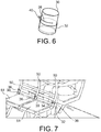
figure 6 , un schéma théorique d'une deuxième réalisation du siège selon l'invention ; -
figure 7 , le siège selon l'invention avec la localisation du mécanisme de la réalisation desfigures 5A et 5B ; -
figures 8A et 8B , deux figures partielles agrandies des deux positions du siège selon l'invention ; -
figures 9A, 9B une deuxième mise en œuvre de la première réalisation ; -
figure 10 , une troisième mise en œuvre de la première réalisation ; et -
figures 11A et 11B , une quatrième mise en œuvre de la première réalisation. - En référence aux
figures 4A et 4B , le principe du siège utilise, schématiquement, une glissière 24 placée longitudinalement dans la partie inférieure du montant 20 du dossier et dans son axe de direction globalement verticale, en position d'utilisation. Un axe de rotation 22, solidaire de l'ossature fixe 23 du siège, et de diamètre légèrement inférieur à la largeur de fente 21 passe dans celle-ci. Théoriquement, le montant 20 du dossier peut donc coulisser dans une direction globalement verticale (axe Z) par rapport à l'ossature fixe 23 du siège. Ceci est représenté par lafigure 4A . - La
figure 4B montre l'état du siège selon l'invention, théoriquement, après le choc du corps d'un passager placé sur un siège placé lui-même derrière le siège représenté par cesfigures 4A et 4B . Le montant 20 du dossier a subi une légère translation vers le haut, grâce à un coulissement du dossier par rapport à l'axe de rotation 22 qui est fixe par rapport à l'ossature fixe 23 du siège. Puis, après cette légère translation vers le haut, le montant 20 du dossier bascule vers l'avant, c'est-à-dire vers la gauche, sur lafigure 4B . - La fixation du montant 20 du dossier par rapport à la structure fixe 23 du siège se fait par enchâssement libérable, c'est-à-dire un enchâssement qui n'est pas à ajustement serré. En effet, une réalisation préférée de ce type de siège consiste à ce que la structure fixe du siège soit constituée d'éléments tubulaires assemblés par des manchons avec un ajustement serré. Dans le cas du siège selon l'invention, l'ajustement du montant 20 du dossier dans l'ossature fixe 23 du siège n'est pas serré. De ce fait, lorsqu'un choc a lieu sur la surface arrière du montant 20 du dossier, celui-ci provoque, entre autres, des vibrations qui font que le montant 20 du dossier sort de son enchâssement non serré par rapport à la partie fixe 23 du siège, l'enchâssement n'étant pas réalisé sur une grande longueur. Une fois libéré de cet enchâssement, le dossier 20, sous l'effet de la force de l'impact sous la surface arrière du dossier 20 bascule naturellement.
- Cette liaison axe de rotation 22/fente 21 permet de combiner une résistance avant/arrière sur une certaine portion de la fente, c'est-à-dire de cet ensemble formant glissière, une rotation aisée au-delà permettant une remise en place facile du dossier 20 dans son enchâssement, après le crash qui a provoqué indirectement ces mouvements. Un élément fusible non représenté sur ces figures consiste, dans ce cas, en une retenue vers le haut, empêchant, avant l'activation, le montant 20 du dossier de se translater. La sollicitation vers le haut du montant 20 du dossier, selon un axe globalement vertical (axe Z) est assez faible dans les essais usuels et peut être limité à 30 kg environ (300 N). L'élément fusible devant céder à environ 300 N peut être un simple rivet en plastique ou en métal alors qu'un élément fusible cédant à 600 N.m autour d'un axe de rotation conduirait à un système relativement lourd.
- En référence aux
figures 5A et 5B , l'extrémité inférieure 30 d'un montant du siège est donc encastrée de façon libérable dans un enchâssement 32 fixe sur la structure fixe du siège. La rotation théorique du montant 20, c'est-à-dire de l'extrémité inférieure 30 du montant 20 par rapport à l'enchâssement 32 est réalisée grâce à un ruban flexible 34 fixé sur une surface extérieure de l'enchâssement 32. Dans la partie supérieure du ruban flexible 34 est fixée une pince-glissière 36 entourant de manière coulissante l'extrémité inférieure 30 du montant 20, comme le montre lafigure 5B , après un choc sur la face arrière du siège, c'est-à-dire sur le montant 20, son extrémité inférieure 30 se libère de sa position enchâssée dans son enchâssement 32 par une translation vers le haut. - Cette élévation du montant 20 et donc de son extrémité inférieure 30 est possible grâce au fait que la pince-glissière 36 n'est pas fixée à cette extrémité inférieure 30, mais l'entoure de façon ajustée.
- Une fois l'extrémité inférieure 30 sortie de son enchâssement 32, le montant 20 pivote sous l'effet de la pression du choc de la tête du passager se trouvant derrière le siège grâce à la flexibilité du ruban flexible 34 fixé à l'enchâssement 32 et solidaire de la pince-glissière 36. Après la sortie du montant 20 par rapport à l'enchâssement 32 de l'ossature fixe du siège, après un crash ou un atterrissage d'urgence, grâce à la pince-glissière 36 et au ruban flexible 34, chaque montant peut être remis dans son enchâssement 32 respectif.
- Sur ces
figures 5A et 5B , le fusible mécanique n'a pas été représenté. - En référence à la
figure 6 , une deuxième réalisation envisagée de cette opération de translation et de rotation peut être effectuée au moyen d'un axe mécanique de rotation 40 fixé à l'enchâssement 32 et auquel est fixée la pince-glissière 36 entourant de manière coulissante l'extrémité inférieure 30 du montant. - La pince-glissière 36 peut être réalisée dans un matériau plastique ou métallique, sa fonction principale étant celle d'un guide, sans reprise des efforts autres que ceux de l'axe mécanique de rotation 40.
- L'axe mécanique de rotation 40 est de préférence métallique, car il ne doit pas se désaxer lors d'un crash et doit permettre de remettre le montant 20 dans sa position initiale après l'essai. Le ruban 34 peut être métallique. Il permet d'obtenir, pour un ou un faible nombre d'essais, la rotation selon un axe perpendiculaire à l'axe principal du ruban. L'avantage de cette réalisation est que l'axe imaginaire perpendiculaire pourra être légèrement désaxé sans cause de difficultés particulières, lors de la remise en position, après essai, du montant dans son enchâssement. De plus, la position dans la direction verticale (axe X) de l'axe de rotation imaginaire ne sera pas fixe, minimisant ainsi les efforts.
- Dans ces deux réalisations, les efforts avant/arrière sont transformés en rotation avec la liaison pivot et les efforts haut/bas conduisent à un simple glissement relatif des montants du dossier par rapport à leur enchâssement.
- En référence à la
figure 7 , sur un siège à deux places 51, trois mécanismes sont nécessaires puisqu'il y est utilisé trois montants 50. Leur extrémité inférieure 30 est donc enchâssée dans leur enchâssement 32 de façon libérable, comme précédemment expliqué. Sur cettefigure 7 , sont également représentées les trois pinces-glissières 36. - Les
figures 8A et 8B montrent plus en détails cette réalisation dans les deux positions avant et après le crash, atterrissage d'urgence ou simple essai. Sur lafigure 8A , chaque montant 50 est fixé par enchâssement par son extrémité inférieure 30 dans l'enchâssement 32 fixe du siège 51. Le ruban 34 est toujours fixé à l'enchâssement 32. - En référence à la
figure 8B , après le choc provoqué sur la face arrière du dossier du siège, chaque montant 50 se libère de son enchâssement respectif 32 grâce au coulissement de la pince-glissière 36 fixée à l'extrémité supérieure du ruban flexible 34, fixé lui-même, par son extrémité inférieure, à l'enchâssement 32. La rotation de chaque montant 50 peut donc avoir lieu. On comprend que le ruban flexible 34 permet de remettre chaque montant 50 dans son enchâssement 32 respectif, après un choc, un accident, un crash, un atterrissage d'urgence ou un essai. - Le ruban flexible 34 peut être remplacé par d'autres éléments flexibles de manière générale.
- En référence aux
figures 9A et 9B , l'élément flexible peut également être constitué d'une lame-ressort 60 fixée, par une extrémité inférieure 62 à l'enchâssement 32 et par une extrémité supérieure 64 à l'extrémité 30 du montant. Cette lame-ressort 60 passe à l'intérieur de la boucle que constitue la pince-glissière 36. Ainsi le montant 30 peut coulisser. - Dans une autre réalisation, l'élément flexible est constitué de deux tiges 70A et 70B flexibles et montées de manière analogue à la lame-ressort 60 des
figures 9A et 9B . - Cet élément flexible peut également être réalisé sous la forme d'un ressort de torsion constitué d'une tige flexible 80 dont l'extrémité supérieure 82 entoure de façon coulissante l'extrémité inférieure 30 du montant. Par une extrémité inférieure 84, cette tige 80 entoure l'enchâssement 32. L'effet de torsion a lieu, notamment, au niveau d'un coude 86 reliant l'extrémité inférieure 84 de la tige 80 à cette dernière. Cette solution de ressort de torsion ne fonctionne pas par une flexion en zone élastique, mais bien par un effet de ressort, permettant au système de pouvoir être mis automatiquement dans sa position après un test ou un accident.
- Ce système translation/pivot n'a pas ici pour objectif de permettre une nouvelle cinématique, mais uniquement de diminuer les contraintes effectives en torsion sur l'axe de rotation.
- Une liaison translation/pivot permet de combiner une résistance avant/arrière sur une certaine portion de la liaison glissière, et une rotation aisée au-delà, permettant une remise en place facile du dossier après le crash. L'élément fusible consiste dans ce cas en une retenue vers le haut, empêchant avant l'activation le pivot d'être dans une zone où le dossier peut effectivement tourner, la sollicitation selon l'axe z étant assez faible dans les essais usuels, et qui peut être limité à 30 kg environ (300 N).
Claims (11)
- Siège pour véhicule destiné à être fixé au plancher d'une cabine d'un véhicule, comprenant :- une ossature fixe comprenant elle-même des pieds et au moins une assise, et- un même nombre de dossier(s) que d'assise(s) fixé(s) à l'ossature fixe et comprenant au moins deux montants (20, 50) placés de façon plus verticale qu'horizontale selon une direction déterminée (Y),caractérisé en ce que les montants (20, 50) sont enchâssés par une extrémité inférieure (30) dans l'ossature de façon libérable par rapport à l'ossature fixe en translation vers le haut de manière à pouvoir se désenchâsser vers le haut sous l'effet d'un choc sur une face arrière du dossier correspondant et sont montés mobile en rotation autour d'au moins un axe fixe de l'ossature fixe de façon à pouvoir pivoter vers l'avant après s'être désenchâssés.
- Siège selon la revendication 1, caractérisé en ce qu'il comprend au moins un fusible mécanique entre chaque montant (20) et l'ossature fixe pour bloquer en translation le montant (20, 50) en dessous d'une force déterminée.
- Siège selon la revendication 2, caractérisé en ce que le pivotement de chaque montant est réalisé avec au moins un élément flexible fixé par une première extrémité inférieure à l'ossature fixe, au niveau d'un enchâssement (32), et, de manière coulissante, par une deuxième extrémité au montant (20, 50), juste au-dessus de l'extrémité inférieure (30) du montant (20, 50), permettant de remettre le montant (20, 50) enchâssé dans l'ossature fixe après un pivotement par rapport à l'ossature fixe.
- Siège selon la revendication 3, caractérisé en ce que la deuxième extrémité dudit au moins un élément (34) comprend une pince-glissière (36) entourant le montant (20, 50).
- Siège selon la revendication 3, caractérisé en ce que l'élément flexible est constitué d'un ruban (34) flexible.
- Siège selon la revendication 3, caractérisé en ce que l'élément flexible est constitué d'une lame-ressort (60).
- Siège selon la revendication 3, caractérisé en ce que l'élément flexible est constitué de deux tiges (70A, 70B) flexibles.
- Siège selon la revendication 3, caractérisé en ce que l'élément flexible est constitué d'un ressort de torsion constitué lui-même d'une tige (80) entourant l'extrémité inférieure (30) du montant par une extrémité supérieure (82) et entourant l'enchâssement (32) par une extrémité inférieure (84).
- Siège selon la revendication 2, caractérisé en ce que le pivotement de chaque montant (20, 50) est réalisé avec au moins un axe mécanique de rotation (22) fixé à l'ossature fixe et une fente (21) du montant (20) dans un sens longitudinal du montant (20, 50) et dans laquelle peut coulisser l'axe mécanique de rotation (21).
- Siège selon la revendication 2, caractérisé en ce que ledit au moins un fusible mécanique est réalisé avec de la colle.
- Siège selon la revendication 2, caractérisé en ce que ledit au moins un fusible mécanique est réalisé avec au moins un rivet, notamment en matière plastique ou métallique.
Applications Claiming Priority (2)
| Application Number | Priority Date | Filing Date | Title |
|---|---|---|---|
| FR1751049A FR3062610B1 (fr) | 2017-02-08 | 2017-02-08 | Siege pour vehicule avec dossier basculant |
| PCT/FR2018/050288 WO2018146412A1 (fr) | 2017-02-08 | 2018-02-06 | Siege pour vehicule avec dossier basculant |
Publications (2)
| Publication Number | Publication Date |
|---|---|
| EP3580087A1 EP3580087A1 (fr) | 2019-12-18 |
| EP3580087B1 true EP3580087B1 (fr) | 2021-01-27 |
Family
ID=58347696
Family Applications (1)
| Application Number | Title | Priority Date | Filing Date |
|---|---|---|---|
| EP18706798.8A Active EP3580087B1 (fr) | 2017-02-08 | 2018-02-06 | Siege pour vehicule avec dossier basculant |
Country Status (6)
| Country | Link |
|---|---|
| US (1) | US11007913B2 (fr) |
| EP (1) | EP3580087B1 (fr) |
| JP (1) | JP7069186B2 (fr) |
| CN (1) | CN110267847B (fr) |
| FR (1) | FR3062610B1 (fr) |
| WO (1) | WO2018146412A1 (fr) |
Families Citing this family (6)
| Publication number | Priority date | Publication date | Assignee | Title |
|---|---|---|---|---|
| US11279488B2 (en) * | 2020-02-20 | 2022-03-22 | B/E Aerospace, Inc. | Seat assembly with sacrificial backrest breakover feature |
| US11400839B2 (en) * | 2020-09-22 | 2022-08-02 | Ford Global Technologies, Llc | Energy absorbing vehicle seat |
| FR3122369B1 (fr) | 2021-05-03 | 2023-06-02 | Expliseat | Siège pour véhicule avec dossier équipé de moyens d’amortissement de choc |
| CA3194555A1 (fr) * | 2022-03-29 | 2023-09-29 | Indiana Mills & Manufacturing, Inc. | Solution de mousse d'autobus modifiee pour un siege d'autobus scolaire |
| US11975840B2 (en) * | 2022-03-31 | 2024-05-07 | B/E Aerospace, Inc. | Fuse link head impact criteria mitigating device |
| CN115946589A (zh) * | 2022-12-19 | 2023-04-11 | 常州大连理工大学智能装备研究院 | 一种汽车座椅骨架 |
Family Cites Families (31)
| Publication number | Priority date | Publication date | Assignee | Title |
|---|---|---|---|---|
| US4145081A (en) * | 1976-12-22 | 1979-03-20 | Ti Accles & Pollock Limited | Vehicle seat |
| US4394047A (en) * | 1981-06-01 | 1983-07-19 | Uop Inc. | Seat back mounting system |
| JPS59136337U (ja) * | 1983-03-03 | 1984-09-11 | 日産車体株式会社 | 衝撃吸収式シ−トバツクフレ−ム |
| DE3808316A1 (de) * | 1988-03-12 | 1989-09-21 | Keiper Recaro Gmbh Co | Rueckenlehne fuer einen fahrzeugsitz, insbesondere einen kraftfahrzeugsitz |
| DE4020057C2 (de) * | 1990-06-23 | 1996-05-09 | Bayer Ag | Fahrzeugsitz |
| US5320308A (en) * | 1991-12-04 | 1994-06-14 | Weber Aircraft, Inc. | Seatback breakover device |
| GB2269986B (en) * | 1992-07-30 | 1997-03-19 | Flight Equip & Eng | Vehicle seats |
| JPH06247198A (ja) * | 1993-02-24 | 1994-09-06 | Koito Ind Ltd | 傾斜ロック装置における衝撃エネルギー吸収機構 |
| AU716487B2 (en) * | 1995-09-14 | 2000-02-24 | Autoliv Development Ab | A seat for use in a vehicle |
| US5722722A (en) * | 1997-01-14 | 1998-03-03 | Lear Corporation | Vehicle seat energy absorber |
| FR2765533B1 (fr) * | 1997-07-03 | 1999-09-03 | Faure Bertrand Equipements Sa | Siege de vehicule dote d'un dispositif de protection du cou en cas de choc arriere |
| US6074004A (en) * | 1998-02-19 | 2000-06-13 | Carmichael; Donald Edwin | Seat back frame for absorbing energy |
| DE19817503C1 (de) * | 1998-04-20 | 1999-09-30 | Faure Bertrand Sitztech Gmbh | Kraftfahrzeugsitz |
| US6485098B1 (en) * | 1998-10-30 | 2002-11-26 | Indiana Mills & Manufacturing, Inc. | Restraint system for a school bus seat |
| US6123388A (en) * | 1998-10-30 | 2000-09-26 | Indiana Mills & Manufacturing, Inc. | Restraint system for a school bus seat |
| DE10102109A1 (de) * | 2000-12-29 | 2002-07-11 | Ingbuero Schimmelpfennig & Bec | Fahrzeugsitz |
| JP2003267108A (ja) * | 2002-03-20 | 2003-09-25 | Mitsubishi Automob Eng Co Ltd | 車両用シート装置 |
| US7354105B2 (en) * | 2004-02-24 | 2008-04-08 | International Truck Intellectual Property Company, Llc | School bus passenger seat with integrated restraints |
| US7059675B2 (en) * | 2004-02-25 | 2006-06-13 | International Truck Intellectual Property Company, Llc | Motion controlling plate for seat and seat system for a mobile vehicle |
| US7055901B2 (en) * | 2004-02-26 | 2006-06-06 | International Truck Intellectual Property Company, Llc | School bus passenger seat with integrated restraints |
| US7377590B2 (en) * | 2004-02-26 | 2008-05-27 | International Truck Intellectual Property Company, Llc | School bus passenger seat with energy absorbing occupant restraint |
| AU2005282527A1 (en) * | 2004-09-07 | 2006-03-16 | Shape Corporation | Plastic energy management beam |
| JP2006336376A (ja) * | 2005-06-03 | 2006-12-14 | Pica Corp | 連結具 |
| US7611197B2 (en) * | 2006-06-26 | 2009-11-03 | International Truck Intellectual Property Company, Llc | Occupant restraint passenger seat assembly with load-sensing energy absorption feature |
| CA2623119A1 (fr) * | 2007-03-02 | 2008-09-02 | M2K, Llc. | Ensemble de siege pour vehicule |
| JP5345420B2 (ja) * | 2009-03-10 | 2013-11-20 | 富士重工業株式会社 | 車両用シート構造 |
| JP2013103674A (ja) * | 2011-11-16 | 2013-05-30 | Toyota Boshoku Corp | 車両用シート |
| DE102014211274A1 (de) * | 2014-06-12 | 2015-12-31 | Suspa Gmbh | Rotationsenergie-Absorber sowie Fahrzeugsitz mit einem derartigen Rotationsenergie-Absorber |
| FR3022863B1 (fr) | 2014-06-27 | 2016-06-10 | Expliseat | Systeme elastique de bloquage d'une tablette de siege de vehicule, en particulier d'aeronef |
| FR3039793B1 (fr) | 2015-08-05 | 2017-09-15 | Expliseat | Siege deformable pour vehicule |
| US10696195B2 (en) * | 2017-11-15 | 2020-06-30 | Key Safety Systems, Inc. | Seat with energy Absorbing seatback |
-
2017
- 2017-02-08 FR FR1751049A patent/FR3062610B1/fr not_active Expired - Fee Related
-
2018
- 2018-02-06 JP JP2019542712A patent/JP7069186B2/ja active Active
- 2018-02-06 WO PCT/FR2018/050288 patent/WO2018146412A1/fr not_active Ceased
- 2018-02-06 US US16/483,594 patent/US11007913B2/en active Active
- 2018-02-06 EP EP18706798.8A patent/EP3580087B1/fr active Active
- 2018-02-06 CN CN201880010792.7A patent/CN110267847B/zh active Active
Non-Patent Citations (1)
| Title |
|---|
| None * |
Also Published As
| Publication number | Publication date |
|---|---|
| FR3062610B1 (fr) | 2019-04-19 |
| EP3580087A1 (fr) | 2019-12-18 |
| CN110267847B (zh) | 2021-10-08 |
| CN110267847A (zh) | 2019-09-20 |
| FR3062610A1 (fr) | 2018-08-10 |
| US11007913B2 (en) | 2021-05-18 |
| WO2018146412A1 (fr) | 2018-08-16 |
| US20200001753A1 (en) | 2020-01-02 |
| JP2020506110A (ja) | 2020-02-27 |
| JP7069186B2 (ja) | 2022-05-17 |
Similar Documents
| Publication | Publication Date | Title |
|---|---|---|
| EP3580087B1 (fr) | Siege pour vehicule avec dossier basculant | |
| EP0659642B1 (fr) | Siège d'aéronef et notamment de giravion, à dispositif d'absorption d'énergie automatiquement ajustable en fonction de la taille de l'occupant | |
| EP1719701B1 (fr) | Siège d'aéronef de sécurité | |
| FR2931403A1 (fr) | Dispositif d'absorption de choc et siege comportant un tel dispositif | |
| EP1291545B1 (fr) | Barre de liaison à absorption d'énergie, et giravion équipé de telles barres de liaison comme barres de suspension d'une boíte de transmission | |
| EP2978633B1 (fr) | Siege de vehicule equipe d'un element rabattable, tel qu'une tablette | |
| EP2360095B1 (fr) | Siège de véhicule anti-crash | |
| EP0072323A1 (fr) | Composants munis d'un dispositif d'absorption d'énergie par déformation plastique et/ou de limitation d'effort, et trains d'atterrissage d'aérodynes équipés de tels composants | |
| FR2612151A1 (fr) | Structure a dispositif d'absorption d'energie et resistant a des efforts dynamiques formant pietement pour siege d'appareil de transport aerien et siege comportant une telle structure | |
| EP2481671A2 (fr) | Dispositif de fixation amovible muni d'un moyen d'accrochage d'une charge externe et d'un moyen de fixation dudit moyen d'accrochage à un aéronef, aéronef et procédé associés | |
| EP1721827B1 (fr) | Procédé et système anti-crash, atterrisseur et aéronef | |
| FR2983135A1 (fr) | Dispositif de fixation d'un siege sur une structure d'un vehicule et siege comportant un tel dispositif de fixation | |
| EP3235680B1 (fr) | Siège d'aéronef tolerant aux déformations du plancher | |
| FR3056552A1 (fr) | Harpon d'ancrage externe pour aeronef | |
| FR2484929A1 (fr) | Pantographe rabattable en cas d'effort frontal anormal | |
| EP0435740B1 (fr) | Siège pour véhicule muni d'une ceinture de sécurité à points de fixation embarqués sur l'armature du siège | |
| FR3049570B1 (fr) | Dispositif de rappel pour retracter un dispositif d'accrochage mobile et aeronef equipe d'un tel dispositif de rappel | |
| FR2776589A1 (fr) | Dispositif d'evacuation de masse, structure de siege, siege et vehicule equipe de ce dispositif | |
| CA2805454C (fr) | Train d'atterrissage pour minimiser un risque d'accrochage d'un cable et aeronef | |
| EP3233565B1 (fr) | Siege escamotable | |
| EP2727762A1 (fr) | Nacelle déformable pour véhicule | |
| FR3102416A1 (fr) | Siège inclinable comprenant un dispositif d’absorption d’énergie | |
| FR2876069A1 (fr) | Ensemble pour vehicule automobile a systeme de protection des membres inferieurs d'un occupant de ce vehicule |
Legal Events
| Date | Code | Title | Description |
|---|---|---|---|
| STAA | Information on the status of an ep patent application or granted ep patent |
Free format text: STATUS: UNKNOWN |
|
| STAA | Information on the status of an ep patent application or granted ep patent |
Free format text: STATUS: THE INTERNATIONAL PUBLICATION HAS BEEN MADE |
|
| PUAI | Public reference made under article 153(3) epc to a published international application that has entered the european phase |
Free format text: ORIGINAL CODE: 0009012 |
|
| STAA | Information on the status of an ep patent application or granted ep patent |
Free format text: STATUS: REQUEST FOR EXAMINATION WAS MADE |
|
| 17P | Request for examination filed |
Effective date: 20190807 |
|
| AK | Designated contracting states |
Kind code of ref document: A1 Designated state(s): AL AT BE BG CH CY CZ DE DK EE ES FI FR GB GR HR HU IE IS IT LI LT LU LV MC MK MT NL NO PL PT RO RS SE SI SK SM TR |
|
| AX | Request for extension of the european patent |
Extension state: BA ME |
|
| DAV | Request for validation of the european patent (deleted) | ||
| DAX | Request for extension of the european patent (deleted) | ||
| GRAP | Despatch of communication of intention to grant a patent |
Free format text: ORIGINAL CODE: EPIDOSNIGR1 |
|
| STAA | Information on the status of an ep patent application or granted ep patent |
Free format text: STATUS: GRANT OF PATENT IS INTENDED |
|
| INTG | Intention to grant announced |
Effective date: 20200924 |
|
| GRAS | Grant fee paid |
Free format text: ORIGINAL CODE: EPIDOSNIGR3 |
|
| GRAA | (expected) grant |
Free format text: ORIGINAL CODE: 0009210 |
|
| STAA | Information on the status of an ep patent application or granted ep patent |
Free format text: STATUS: THE PATENT HAS BEEN GRANTED |
|
| AK | Designated contracting states |
Kind code of ref document: B1 Designated state(s): AL AT BE BG CH CY CZ DE DK EE ES FI FR GB GR HR HU IE IS IT LI LT LU LV MC MK MT NL NO PL PT RO RS SE SI SK SM TR |
|
| REG | Reference to a national code |
Ref country code: GB Ref legal event code: FG4D Free format text: NOT ENGLISH |
|
| REG | Reference to a national code |
Ref country code: CH Ref legal event code: EP |
|
| REG | Reference to a national code |
Ref country code: AT Ref legal event code: REF Ref document number: 1358054 Country of ref document: AT Kind code of ref document: T Effective date: 20210215 |
|
| REG | Reference to a national code |
Ref country code: IE Ref legal event code: FG4D Free format text: LANGUAGE OF EP DOCUMENT: FRENCH |
|
| REG | Reference to a national code |
Ref country code: DE Ref legal event code: R096 Ref document number: 602018012310 Country of ref document: DE |
|
| REG | Reference to a national code |
Ref country code: NL Ref legal event code: MP Effective date: 20210127 |
|
| REG | Reference to a national code |
Ref country code: LT Ref legal event code: MG9D |
|
| REG | Reference to a national code |
Ref country code: AT Ref legal event code: MK05 Ref document number: 1358054 Country of ref document: AT Kind code of ref document: T Effective date: 20210127 |
|
| PG25 | Lapsed in a contracting state [announced via postgrant information from national office to epo] |
Ref country code: PT Free format text: LAPSE BECAUSE OF FAILURE TO SUBMIT A TRANSLATION OF THE DESCRIPTION OR TO PAY THE FEE WITHIN THE PRESCRIBED TIME-LIMIT Effective date: 20210527 Ref country code: NO Free format text: LAPSE BECAUSE OF FAILURE TO SUBMIT A TRANSLATION OF THE DESCRIPTION OR TO PAY THE FEE WITHIN THE PRESCRIBED TIME-LIMIT Effective date: 20210427 Ref country code: LT Free format text: LAPSE BECAUSE OF FAILURE TO SUBMIT A TRANSLATION OF THE DESCRIPTION OR TO PAY THE FEE WITHIN THE PRESCRIBED TIME-LIMIT Effective date: 20210127 Ref country code: BG Free format text: LAPSE BECAUSE OF FAILURE TO SUBMIT A TRANSLATION OF THE DESCRIPTION OR TO PAY THE FEE WITHIN THE PRESCRIBED TIME-LIMIT Effective date: 20210427 Ref country code: HR Free format text: LAPSE BECAUSE OF FAILURE TO SUBMIT A TRANSLATION OF THE DESCRIPTION OR TO PAY THE FEE WITHIN THE PRESCRIBED TIME-LIMIT Effective date: 20210127 Ref country code: GR Free format text: LAPSE BECAUSE OF FAILURE TO SUBMIT A TRANSLATION OF THE DESCRIPTION OR TO PAY THE FEE WITHIN THE PRESCRIBED TIME-LIMIT Effective date: 20210428 Ref country code: FI Free format text: LAPSE BECAUSE OF FAILURE TO SUBMIT A TRANSLATION OF THE DESCRIPTION OR TO PAY THE FEE WITHIN THE PRESCRIBED TIME-LIMIT Effective date: 20210127 |
|
| PG25 | Lapsed in a contracting state [announced via postgrant information from national office to epo] |
Ref country code: SE Free format text: LAPSE BECAUSE OF FAILURE TO SUBMIT A TRANSLATION OF THE DESCRIPTION OR TO PAY THE FEE WITHIN THE PRESCRIBED TIME-LIMIT Effective date: 20210127 Ref country code: AT Free format text: LAPSE BECAUSE OF FAILURE TO SUBMIT A TRANSLATION OF THE DESCRIPTION OR TO PAY THE FEE WITHIN THE PRESCRIBED TIME-LIMIT Effective date: 20210127 Ref country code: PL Free format text: LAPSE BECAUSE OF FAILURE TO SUBMIT A TRANSLATION OF THE DESCRIPTION OR TO PAY THE FEE WITHIN THE PRESCRIBED TIME-LIMIT Effective date: 20210127 Ref country code: LV Free format text: LAPSE BECAUSE OF FAILURE TO SUBMIT A TRANSLATION OF THE DESCRIPTION OR TO PAY THE FEE WITHIN THE PRESCRIBED TIME-LIMIT Effective date: 20210127 Ref country code: RS Free format text: LAPSE BECAUSE OF FAILURE TO SUBMIT A TRANSLATION OF THE DESCRIPTION OR TO PAY THE FEE WITHIN THE PRESCRIBED TIME-LIMIT Effective date: 20210127 |
|
| PG25 | Lapsed in a contracting state [announced via postgrant information from national office to epo] |
Ref country code: IS Free format text: LAPSE BECAUSE OF FAILURE TO SUBMIT A TRANSLATION OF THE DESCRIPTION OR TO PAY THE FEE WITHIN THE PRESCRIBED TIME-LIMIT Effective date: 20210527 |
|
| REG | Reference to a national code |
Ref country code: BE Ref legal event code: MM Effective date: 20210228 |
|
| REG | Reference to a national code |
Ref country code: DE Ref legal event code: R097 Ref document number: 602018012310 Country of ref document: DE |
|
| PG25 | Lapsed in a contracting state [announced via postgrant information from national office to epo] |
Ref country code: EE Free format text: LAPSE BECAUSE OF FAILURE TO SUBMIT A TRANSLATION OF THE DESCRIPTION OR TO PAY THE FEE WITHIN THE PRESCRIBED TIME-LIMIT Effective date: 20210127 Ref country code: CZ Free format text: LAPSE BECAUSE OF FAILURE TO SUBMIT A TRANSLATION OF THE DESCRIPTION OR TO PAY THE FEE WITHIN THE PRESCRIBED TIME-LIMIT Effective date: 20210127 Ref country code: LI Free format text: LAPSE BECAUSE OF NON-PAYMENT OF DUE FEES Effective date: 20210228 Ref country code: MC Free format text: LAPSE BECAUSE OF FAILURE TO SUBMIT A TRANSLATION OF THE DESCRIPTION OR TO PAY THE FEE WITHIN THE PRESCRIBED TIME-LIMIT Effective date: 20210127 Ref country code: LU Free format text: LAPSE BECAUSE OF NON-PAYMENT OF DUE FEES Effective date: 20210206 Ref country code: SM Free format text: LAPSE BECAUSE OF FAILURE TO SUBMIT A TRANSLATION OF THE DESCRIPTION OR TO PAY THE FEE WITHIN THE PRESCRIBED TIME-LIMIT Effective date: 20210127 Ref country code: CH Free format text: LAPSE BECAUSE OF NON-PAYMENT OF DUE FEES Effective date: 20210228 |
|
| PG25 | Lapsed in a contracting state [announced via postgrant information from national office to epo] |
Ref country code: RO Free format text: LAPSE BECAUSE OF FAILURE TO SUBMIT A TRANSLATION OF THE DESCRIPTION OR TO PAY THE FEE WITHIN THE PRESCRIBED TIME-LIMIT Effective date: 20210127 Ref country code: SK Free format text: LAPSE BECAUSE OF FAILURE TO SUBMIT A TRANSLATION OF THE DESCRIPTION OR TO PAY THE FEE WITHIN THE PRESCRIBED TIME-LIMIT Effective date: 20210127 Ref country code: DK Free format text: LAPSE BECAUSE OF FAILURE TO SUBMIT A TRANSLATION OF THE DESCRIPTION OR TO PAY THE FEE WITHIN THE PRESCRIBED TIME-LIMIT Effective date: 20210127 |
|
| PLBE | No opposition filed within time limit |
Free format text: ORIGINAL CODE: 0009261 |
|
| STAA | Information on the status of an ep patent application or granted ep patent |
Free format text: STATUS: NO OPPOSITION FILED WITHIN TIME LIMIT |
|
| 26N | No opposition filed |
Effective date: 20211028 |
|
| PG25 | Lapsed in a contracting state [announced via postgrant information from national office to epo] |
Ref country code: IE Free format text: LAPSE BECAUSE OF NON-PAYMENT OF DUE FEES Effective date: 20210206 Ref country code: AL Free format text: LAPSE BECAUSE OF FAILURE TO SUBMIT A TRANSLATION OF THE DESCRIPTION OR TO PAY THE FEE WITHIN THE PRESCRIBED TIME-LIMIT Effective date: 20210127 Ref country code: ES Free format text: LAPSE BECAUSE OF FAILURE TO SUBMIT A TRANSLATION OF THE DESCRIPTION OR TO PAY THE FEE WITHIN THE PRESCRIBED TIME-LIMIT Effective date: 20210127 |
|
| PG25 | Lapsed in a contracting state [announced via postgrant information from national office to epo] |
Ref country code: SI Free format text: LAPSE BECAUSE OF FAILURE TO SUBMIT A TRANSLATION OF THE DESCRIPTION OR TO PAY THE FEE WITHIN THE PRESCRIBED TIME-LIMIT Effective date: 20210127 |
|
| PG25 | Lapsed in a contracting state [announced via postgrant information from national office to epo] |
Ref country code: IS Free format text: LAPSE BECAUSE OF FAILURE TO SUBMIT A TRANSLATION OF THE DESCRIPTION OR TO PAY THE FEE WITHIN THE PRESCRIBED TIME-LIMIT Effective date: 20210527 |
|
| PG25 | Lapsed in a contracting state [announced via postgrant information from national office to epo] |
Ref country code: BE Free format text: LAPSE BECAUSE OF NON-PAYMENT OF DUE FEES Effective date: 20210228 |
|
| P01 | Opt-out of the competence of the unified patent court (upc) registered |
Effective date: 20230516 |
|
| PG25 | Lapsed in a contracting state [announced via postgrant information from national office to epo] |
Ref country code: NL Free format text: LAPSE BECAUSE OF NON-PAYMENT OF DUE FEES Effective date: 20210127 Ref country code: CY Free format text: LAPSE BECAUSE OF FAILURE TO SUBMIT A TRANSLATION OF THE DESCRIPTION OR TO PAY THE FEE WITHIN THE PRESCRIBED TIME-LIMIT Effective date: 20210127 |
|
| PG25 | Lapsed in a contracting state [announced via postgrant information from national office to epo] |
Ref country code: HU Free format text: LAPSE BECAUSE OF FAILURE TO SUBMIT A TRANSLATION OF THE DESCRIPTION OR TO PAY THE FEE WITHIN THE PRESCRIBED TIME-LIMIT; INVALID AB INITIO Effective date: 20180206 |
|
| PG25 | Lapsed in a contracting state [announced via postgrant information from national office to epo] |
Ref country code: MK Free format text: LAPSE BECAUSE OF FAILURE TO SUBMIT A TRANSLATION OF THE DESCRIPTION OR TO PAY THE FEE WITHIN THE PRESCRIBED TIME-LIMIT Effective date: 20210127 |
|
| PG25 | Lapsed in a contracting state [announced via postgrant information from national office to epo] |
Ref country code: MT Free format text: LAPSE BECAUSE OF FAILURE TO SUBMIT A TRANSLATION OF THE DESCRIPTION OR TO PAY THE FEE WITHIN THE PRESCRIBED TIME-LIMIT Effective date: 20210127 |
|
| PGFP | Annual fee paid to national office [announced via postgrant information from national office to epo] |
Ref country code: GB Payment date: 20260225 Year of fee payment: 9 |
|
| PGFP | Annual fee paid to national office [announced via postgrant information from national office to epo] |
Ref country code: DE Payment date: 20260225 Year of fee payment: 9 |
|
| PGFP | Annual fee paid to national office [announced via postgrant information from national office to epo] |
Ref country code: IT Payment date: 20260225 Year of fee payment: 9 |
|
| PGFP | Annual fee paid to national office [announced via postgrant information from national office to epo] |
Ref country code: FR Payment date: 20260223 Year of fee payment: 9 |
|
| PGFP | Annual fee paid to national office [announced via postgrant information from national office to epo] |
Ref country code: TR Payment date: 20260205 Year of fee payment: 9 |