EP3580408B1 - Bâtiment modulaire pouvant être réutilisé et son procédé de montage - Google Patents
Bâtiment modulaire pouvant être réutilisé et son procédé de montage Download PDFInfo
- Publication number
- EP3580408B1 EP3580408B1 EP18709478.4A EP18709478A EP3580408B1 EP 3580408 B1 EP3580408 B1 EP 3580408B1 EP 18709478 A EP18709478 A EP 18709478A EP 3580408 B1 EP3580408 B1 EP 3580408B1
- Authority
- EP
- European Patent Office
- Prior art keywords
- steel
- predetermined number
- frames
- elongated
- rectangular
- Prior art date
- Legal status (The legal status is an assumption and is not a legal conclusion. Google has not performed a legal analysis and makes no representation as to the accuracy of the status listed.)
- Active
Links
Images


Classifications
-
- E—FIXED CONSTRUCTIONS
- E04—BUILDING
- E04H—BUILDINGS OR LIKE STRUCTURES FOR PARTICULAR PURPOSES; SWIMMING OR SPLASH BATHS OR POOLS; MASTS; FENCING; TENTS OR CANOPIES, IN GENERAL
- E04H1/00—Buildings or groups of buildings for dwelling or office purposes; General layout, e.g. modular co-ordination or staggered storeys
- E04H1/12—Small buildings or other erections for limited occupation, erected in the open air or arranged in buildings, e.g. kiosks, waiting shelters for bus stops or for filling stations, roofs for railway platforms, watchmen's huts or dressing cubicles
- E04H1/1205—Small buildings erected in the open air
-
- E—FIXED CONSTRUCTIONS
- E04—BUILDING
- E04B—GENERAL BUILDING CONSTRUCTIONS; WALLS, e.g. PARTITIONS; ROOFS; FLOORS; CEILINGS; INSULATION OR OTHER PROTECTION OF BUILDINGS
- E04B1/00—Constructions in general; Structures which are not restricted either to walls, e.g. partitions, or floors or ceilings or roofs
- E04B1/18—Structures comprising elongated load-supporting parts, e.g. columns, girders, skeletons
- E04B1/24—Structures comprising elongated load-supporting parts, e.g. columns, girders, skeletons the supporting parts consisting of metal
-
- E—FIXED CONSTRUCTIONS
- E04—BUILDING
- E04H—BUILDINGS OR LIKE STRUCTURES FOR PARTICULAR PURPOSES; SWIMMING OR SPLASH BATHS OR POOLS; MASTS; FENCING; TENTS OR CANOPIES, IN GENERAL
- E04H1/00—Buildings or groups of buildings for dwelling or office purposes; General layout, e.g. modular co-ordination or staggered storeys
- E04H1/005—Modulation co-ordination
-
- E—FIXED CONSTRUCTIONS
- E04—BUILDING
- E04B—GENERAL BUILDING CONSTRUCTIONS; WALLS, e.g. PARTITIONS; ROOFS; FLOORS; CEILINGS; INSULATION OR OTHER PROTECTION OF BUILDINGS
- E04B1/00—Constructions in general; Structures which are not restricted either to walls, e.g. partitions, or floors or ceilings or roofs
- E04B1/18—Structures comprising elongated load-supporting parts, e.g. columns, girders, skeletons
- E04B1/24—Structures comprising elongated load-supporting parts, e.g. columns, girders, skeletons the supporting parts consisting of metal
- E04B1/2403—Connection details of the elongated load-supporting parts
- E04B2001/2415—Brackets, gussets, joining plates
-
- E—FIXED CONSTRUCTIONS
- E04—BUILDING
- E04B—GENERAL BUILDING CONSTRUCTIONS; WALLS, e.g. PARTITIONS; ROOFS; FLOORS; CEILINGS; INSULATION OR OTHER PROTECTION OF BUILDINGS
- E04B1/00—Constructions in general; Structures which are not restricted either to walls, e.g. partitions, or floors or ceilings or roofs
- E04B1/18—Structures comprising elongated load-supporting parts, e.g. columns, girders, skeletons
- E04B1/24—Structures comprising elongated load-supporting parts, e.g. columns, girders, skeletons the supporting parts consisting of metal
- E04B1/2403—Connection details of the elongated load-supporting parts
- E04B2001/2421—Socket type connectors
-
- E—FIXED CONSTRUCTIONS
- E04—BUILDING
- E04B—GENERAL BUILDING CONSTRUCTIONS; WALLS, e.g. PARTITIONS; ROOFS; FLOORS; CEILINGS; INSULATION OR OTHER PROTECTION OF BUILDINGS
- E04B1/00—Constructions in general; Structures which are not restricted either to walls, e.g. partitions, or floors or ceilings or roofs
- E04B1/18—Structures comprising elongated load-supporting parts, e.g. columns, girders, skeletons
- E04B1/24—Structures comprising elongated load-supporting parts, e.g. columns, girders, skeletons the supporting parts consisting of metal
- E04B1/2403—Connection details of the elongated load-supporting parts
- E04B2001/2433—Connection details of the elongated load-supporting parts using a removable key
-
- E—FIXED CONSTRUCTIONS
- E04—BUILDING
- E04B—GENERAL BUILDING CONSTRUCTIONS; WALLS, e.g. PARTITIONS; ROOFS; FLOORS; CEILINGS; INSULATION OR OTHER PROTECTION OF BUILDINGS
- E04B1/00—Constructions in general; Structures which are not restricted either to walls, e.g. partitions, or floors or ceilings or roofs
- E04B1/18—Structures comprising elongated load-supporting parts, e.g. columns, girders, skeletons
- E04B1/24—Structures comprising elongated load-supporting parts, e.g. columns, girders, skeletons the supporting parts consisting of metal
- E04B1/2403—Connection details of the elongated load-supporting parts
- E04B2001/2451—Connections between closed section profiles
-
- E—FIXED CONSTRUCTIONS
- E04—BUILDING
- E04B—GENERAL BUILDING CONSTRUCTIONS; WALLS, e.g. PARTITIONS; ROOFS; FLOORS; CEILINGS; INSULATION OR OTHER PROTECTION OF BUILDINGS
- E04B1/00—Constructions in general; Structures which are not restricted either to walls, e.g. partitions, or floors or ceilings or roofs
- E04B1/18—Structures comprising elongated load-supporting parts, e.g. columns, girders, skeletons
- E04B1/24—Structures comprising elongated load-supporting parts, e.g. columns, girders, skeletons the supporting parts consisting of metal
- E04B1/2403—Connection details of the elongated load-supporting parts
- E04B2001/2454—Connections between open and closed section profiles
-
- E—FIXED CONSTRUCTIONS
- E04—BUILDING
- E04H—BUILDINGS OR LIKE STRUCTURES FOR PARTICULAR PURPOSES; SWIMMING OR SPLASH BATHS OR POOLS; MASTS; FENCING; TENTS OR CANOPIES, IN GENERAL
- E04H1/00—Buildings or groups of buildings for dwelling or office purposes; General layout, e.g. modular co-ordination or staggered storeys
- E04H1/12—Small buildings or other erections for limited occupation, erected in the open air or arranged in buildings, e.g. kiosks, waiting shelters for bus stops or for filling stations, roofs for railway platforms, watchmen's huts or dressing cubicles
- E04H2001/1283—Small buildings of the ISO containers type
-
- E—FIXED CONSTRUCTIONS
- E04—BUILDING
- E04H—BUILDINGS OR LIKE STRUCTURES FOR PARTICULAR PURPOSES; SWIMMING OR SPLASH BATHS OR POOLS; MASTS; FENCING; TENTS OR CANOPIES, IN GENERAL
- E04H3/00—Buildings or groups of buildings for public or similar purposes; Institutions, e.g. infirmaries or prisons
- E04H3/02—Hotels; Motels; Coffee-houses; Restaurants; Shops; Department stores
Definitions
- the invention relates to a reusable modular building that in use comprises a self-supporting steel skeleton.
- the invention also relates to a method for erecting the modular reusable building.
- aluminum-based structures it is for example very difficult to make them so-called mouse-close, which is very important in particular for catering and restaurant facilities. It is also difficult to prevent leakages in aluminum-based structures and to render them air-tight in a cost-effective way.
- Another disadvantage of aluminum-based structures is that they comprise roofs having a high ridge which provides them with excessive volumes. Moreover, such roofs render the installation of ceiling systems more complicated.
- a further disadvantage of aluminum-based structures is that they comprise heavy supporting pillars which render erecting and dismantling of the aluminum-based structures more complicated.
- An additional disadvantage of aluminum-based structures is that they comprise aluminum rafters having ends parts that need to be anchored to the supporting surface on which they are positioned.
- Aluminum-based structures generally also suffer from cold bridges that cause low thermal isolation values. Furthermore, especially regarding kitchen and restaurant facilities regulations with respect to isolation, fire resistance and the strength of the floors in terms of load capacity and stability get increasingly strict. As a result thereof, aluminum-based structures can no longer meet those regulations and therefore cannot be used any longer. The aforementioned disadvantages render aluminum-based structures unsuitable for long-term housing projects. In addition, any one of extensions, modifications and replacements of parts of aluminum-based structures is often quite expensive. Moreover, erecting and dismantling aluminum-based structures is labor-intensive and hence expensive.
- a well-known disadvantage of container-based buildings is that their interior arrangement is limited because of the fixed sizes of the containers. In particular, they do not offer any free span which is not suitable for restaurant facilities. In addition, this type of buildings requires a considerable amount of maintenance. Furthermore, shipping and storage of containers is expensive as they are bulky.
- the document DE3303190 shows a reusable modular building comprising the features of the preamble of claim 1.
- a reusable modular building that in use comprises a self-supporting steel skeleton comprising a predetermined number of rectangular steel floor frames that each comprise elongated steel profiles that are releasably coupled to each other with releasable coupling elements; a predetermined number of rectangular steel roof frames that each comprise elongated steel profiles that are releasably coupled to each other with releasable coupling elements; a predetermined number of steel supporting pillars that are releasably connected under right angles with the elongated steel profiles of both the predetermined number of rectangular steel floor frames and the predetermined number of rectangular steel roof frames so as to releasably interconnect said predetermined number of rectangular steel floor frames and said predetermined number of rectangular steel roof frames; wherein each elongated steel profile of both the predetermined number of rectangular steel floor frames and the predetermined number of the rectangular steel roof frames is provided with at least two tubular steel
- the present invention provides a modular building that can more easily and therefore quickly be erected and dismantled than reusable buildings known in the art.
- All described parts of the self-supporting steel skeleton are releasably coupled to each other on site using releasable coupling means such as steel nuts and bolts.
- releasable coupling means such as steel nuts and bolts.
- welding of any parts of the self-supporting steel skeleton can be avoided.
- This makes erecting the modular building less complex and less time-consuming.
- the reusability of the individual parts e.g. the elongated steel profiles of the floor and roof frames, the steel supporting pillars, the wall panels, and therefore of the modular building as a whole is enhanced.
- the modular building according to the invention offers an enhanced flexibility with respect to its configuration as any desired number of rectangular steel floor and roof frames can be used and any desired free span inside the modular building can be realized. Therefore, any requirements regarding size and interior layout of the modular building according to the invention that are defined by its intended use, e.g. as a restaurant facility, can easily be fulfilled. Furthermore, due to the simple and robust construction of the self-supporting steel skeleton, the modular building according to the invention can be reused many times. Hence, the reusable modular building according to the present invention has a significantly improved sustainability. From the above, the skilled person will appreciate that the reusable modular building according to the invention pre-empts or at least reduces the drawbacks mentioned above regarding buildings known in the art.
- each elongated steel profile of both the predetermined number of rectangular steel floor frames and the predetermined number of the rectangular steel roof frames has a longitudinal centerline that is at a right angle with respect to the longitudinal centerline of each tubular steel receiving member it is associated with.
- each elongated steel profile of both the predetermined number of rectangular steel floor frames and the predetermined number of rectangular steel roof frames is provided with a first predetermined hole pattern, wherein the holes of the first predetermined hole pattern are configured and arranged to receive releasable coupling elements to releasably couple adjacently arranged rectangular steel floor frames of the predetermined number of rectangular steel floor frames and adjacently arranged rectangular steel roof frames of the predetermined number of rectangular steel roof frames, respectively.
- releasable coupling elements e.g. steel nuts and bolts
- the self-supporting steel skeleton can be erected much faster and with less cost.
- the reusability of the elongated steel profiles is considerably enhanced.
- a steel supporting structure is provided that is arranged to enclose the periphery of the releasably coupled adjacently arranged rectangular steel floor frames of the predetermined number of rectangular steel floor frames, the steel supporting structure comprising steel supporting profiles each of which has a Z-shape and is arranged to receive and support at least a first wall panel of a predetermined number of wall panels, wherein each of the steel supporting profiles is also provided with the first predetermined hole pattern to releasably couple each of the steel supporting profiles with elongated steel profiles of the predetermined number of rectangular steel floor frames that have a free side that faces away from the interior of the self-supporting steel skeleton.
- the steel supporting structure provides a slit in which wall panels can at least partially be received. Furthermore, the steel supporting structure supports the wall panels received in the slit.
- a steel eaves frame is provided that is arranged to enclose the periphery of the releasably coupled adjacently arranged rectangular steel roof frames of the predetermined number of rectangular steel roof frames, the steel eaves frame comprising steel eaves profiles each of which is arranged to support at least a first eaves panel of a predetermined number of eaves panels, wherein each of the steel eaves profiles is also provided with the first predetermined hole pattern to releasably couple each of the steel eaves profiles with elongated steel profiles of the predetermined number of rectangular steel roof frames that have a free side that faces away from the interior of the self-supporting steel skeleton.
- an edge of the roof is provided.
- Behind the eaves panels that are releasably coupled to the steel eaves profiles of the steel eaves frame facilities comprising at least one of a gutter and lighting can be provided.
- each steel supporting pillar of the predetermined number of steel supporting pillars is provided with a second predetermined hole pattern, wherein the holes of the second predetermined hole pattern are configured and arranged to receive releasable clamping mechanisms of a predetermined number of releasable clamping mechanisms to releasably clamp the predetermined number of wall panels to the steel supporting pillars.
- the wall panels that are either directly or indirectly supported by the steel supporting structure can releasably be clamped to the self-supporting steel skeleton.
- the wall panels are at least one of directly and indirectly supported by at least one of the steel supporting structure and the releasable clamping mechanism.
- each releasable clamping mechanism is arranged between at least two wall panels of the predetermined number of wall panels to releasably clamp the at least two wall panels to a side of at least one steel supporting pillar that faces away from the interior of the self-supporting steel skeleton. In this way, the formation of cold bridges can be prevented which significantly improves thermal isolation of the modular building according to the invention.
- each releasable clamping mechanism comprises a steel supporting plate provided with a first steel nut, the steel supporting plate being connected with at least one steel supporting pillar such that the first steel nut faces towards the at least two wall panels to be releasably clamped; a steel threaded rod having a predetermined length that is determined by the thickness of the at least two wall panels that are to be releasably clamped, wherein in use of the releasable clamping mechanism, a first end part of the steel threaded rod is releasably connected with the first steel nut of the steel supporting plate; at least a first resilient sealing member that in use of the releasable clamping mechanism is arranged in abutting contact with at least one of the at least two wall panels to be releasably clamped; a steel retaining plate that is provided with a hole that, in use of the releasable clamping mechanism, is configured and
- each releasable clamping mechanism comprises at least a first spacer element that, in use of the releasable clamping mechanism, is connected with the steel threaded rod and arranged between two adjacent wall panels to keep them at a predefined distance with respect to each other. In this way, it is very easy to keep two adjacent wall panels that need to be installed at the correct predefined distance with respect to each other. After installation of the wall panels, the at least first spacer element can either be left on the steel threaded rod or be removed from it.
- each releasable clamping mechanism comprises at least a first elongated cover element that, in use of the releasable clamping mechanism, is releasably connected with the steel retaining plate via a snap connection.
- the first elongated cover element prevents the releasable clamping mechanism to which it is attached to be accessible from the outside. Furthermore, it prevents the releasable clamping mechanism to be subjected to pollution from the environment in which the reusable modular building according to the invention is used.
- the first elongated cover element also provides an aesthetic finish for the exterior of the reusable modular building.
- the second steel nut and the steel retaining plate are connected to each other so as to form one integrated component.
- the steel supporting profiles are provided with a third predetermined hole pattern, wherein the holes of the third predetermined hole pattern are configured and arranged to drain rainwater.
- the tubular steel receiving members are welded to the elongated steel profiles.
- the at least one steel elongated protrusion is at least one of rod-shaped and tubular-shaped.
- At least one rectangular steel floor frame of the predetermined number of rectangular steel floor frames and/or at least one rectangular steel roof frame of the predetermined number of rectangular steel roof frames is provided with a predetermined number of wooden reinforcement beams, wherein each wooden reinforcement beam of the predetermined number of wooden reinforcement beams is arranged at right angles with respect to oppositely arranged elongated steel profiles of the respective at least one rectangular steel floor frame and/or the at least one rectangular steel roof frame.
- the rectangular steel floor frames and the rectangular steel roof frames that are provided with wooden reinforcement beams have a higher strength and load capacity.
- wooden reinforcement beams are applied in the rectangular steel floor and roof frames because this is advantageous with respect to for example mounting of installation modules inside the modular building and positioning of the rectangular steel floor and roof frames during erection of the modular building according to the invention.
- At least one wooden reinforcement beam of the predetermined number of wooden reinforcement beams is provided with a predetermined number of through holes wherein at least two through holes of the predetermined number of through holes are each provided with an elongated steel element, each of the elongated steel elements being provided with threaded sections at its free ends, each of the threaded sections being releasably coupled with a threaded tubular steel element, one threaded tubular steel element is coupled with a securing element that, in use of the elongated steel element, is arranged to confine the elongated steel element to the respective through hole of the respective wooden reinforcement beam in which it is arranged, the other threaded steel tubular element, in use of the elongated steel element, is associated with at least one of a threaded steel ring-shaped element and a sealing element.
- each one of the four threaded tubular elements is associated at one of its open sides with a threaded steel ring-shaped element, e.g. a lifting eye, that can be releasably coupled with a sling.
- a threaded steel ring-shaped element e.g. a lifting eye
- the wooden reinforcement beams are equipped to enable the rectangular steel floor frames to be positioned tightly against each other.
- the lifting-eyes can be replaced by sealing elements to cover the through holes in the wooden reinforcement beams.
- At least one elongated steel profile of the predetermined number of rectangular steel roof frames is a truss beam.
- a predetermined number of shoring elements is provided that, in use of the reusable modular building, are arranged to interconnect elongated steel profiles of the predetermined number of rectangular steel roof frames and steel supporting pillars of the predetermined number of steel supporting pillars.
- the steel supporting pillars and the rectangular steel roof frames can be arranged perpendicular and level.
- a rigid self-supporting steel skeleton is obtained.
- the shoring elements have an adjustable length. This enables an even more convenient way of erecting the self-supporting steel skeleton of the modular building.
- the elongated steel profiles of at least one of the predetermined number of rectangular steel floor frames and the predetermined number of rectangular steel roof frames are provided with steel reinforcement elements. In this way the local strength and load capacity of the elongated steel profiles and therefore of the rectangular steel floor and roof frames can be increased.
- the releasable coupling elements are steel nuts and bolts.
- the self-supporting steel skeleton comprises at least one storey.
- the reusable modular building according to the invention can have one storey but that depending on the intended use of the reusable modular building two, three or more storeys can also be envisaged.
- a predetermined number of incrementing frames is provided that in use of the reusable modular building are releasably coupled to a predetermined number of the rectangular steel roof frames to provide the self-supporting steel skeleton with at least one pitched roof section.
- each incrementing frame of the predetermined number of incrementing frames is provided with a predetermined number of wooden reinforcement beams.
- the incrementing frames that are provided with wooden reinforcement beams have a higher strength and load capacity. It is noted that instead of steel reinforcement beams, wooden reinforcement beams are applied in the rectangular steel floor and roof frames because this is advantageous with respect to for example mounting of roof panels and installation of air ducts of an air management system.
- a predetermined number of roof panels is provided and wherein each roof panel of the predetermined number of roof panels is releasably coupled to at least one incrementing frame of the predetermined number of incrementing frames via at least one of the wooden reinforcement beams of the predetermined number of wooden reinforcement beams that is associated with the respective at least one incrementing frame.
- the roof panels can comprise at least one of photovoltaic solar panels and solar collector panels of a solar water heater system.
- a predetermined number of parts of a ceiling system is provided, each of which parts is provided with a fourth predetermined hole pattern that is also provided to each elongated steel profile of the predetermined number of rectangular steel roof frames, wherein the holes of the fourth predetermined hole pattern are configured and arranged to receive releasable coupling elements to releasably couple at least a first part of the predetermined number of parts of the ceiling system to a first rectangular steel roof frame of the predetermined number of rectangular steel roof frames.
- a method for erecting a reusable modular building that in use comprises a self-supporting steel skeleton, the method comprising the steps of providing a predetermined number of elongated steel profiles that are provided with at least two tubular steel receiving members that are arranged at opposite ends of each respective elongated steel profile and releasably coupling the elongated steel profiles to each other with releasable coupling elements to form a predetermined number of rectangular steel floor frames; providing a predetermined number of elongated steel profiles that are provided with at least two tubular steel receiving members that are arranged at opposite ends of each respective elongated steel profile and releasably coupling the elongated steel profiles to each other with releasable coupling elements to form a predetermined number of rectangular steel roof frames; providing a predetermined number of steel supporting pillars each of which is provided at its ends with at least one elongated steel protrusion and re
- the method further comprises the step of releasably coupling adjacently arranged rectangular steel floor frames of the predetermined number of rectangular steel floor frames and adjacently arranged rectangular steel roof frames of the predetermined number of rectangular steel roof frames, respectively using releasable coupling elements, wherein each elongated steel profile of both the predetermined number of rectangular steel floor frames and the predetermined number of rectangular steel roof frames is provided with a first predetermined hole pattern, wherein the holes of the first predetermined hole pattern are configured and arranged to receive the releasable coupling elements.
- the elongated steel profiles with the first predetermined hole pattern By providing the elongated steel profiles with the first predetermined hole pattern, coupling of the required number of rectangular steel floor frames to one another and of the required number of rectangular steel roof frames to one another, respectively, can be done more easily and therefore faster.
- releasable coupling elements e.g. steel nuts and bolts
- the method according to the present invention enables the self-supporting steel skeleton to be erected much faster and with less cost.
- the reusability of the elongated steel profiles is considerably enhanced.
- the method further comprises the steps of providing Z-shaped steel supporting profiles that are provided with the first predetermined hole pattern; releasably coupling each of the Z-shaped steel supporting profiles using releasable coupling elements with elongated steel profiles of the predetermined number of rectangular steel floor frames that have a free side that faces away from the interior of the self-supporting steel skeleton to provide a steel supporting structure that encloses the periphery of the releasably coupled adjacently arranged rectangular steel floor frames of the predetermined number of rectangular steel floor frames; providing a predetermined number of wall panels, wherein each of the Z-shaped steel supporting profiles receives and supports at least a first wall panel of the predetermined number of wall panels.
- the steel supporting structure provides a slit in which wall panels can at least partially be received. Furthermore, the steel supporting structure supports the wall panels received in the slit.
- the method further comprises the steps of providing steel eaves profiles that are provided with the first predetermined hole pattern; releasably coupling each of the steel eaves profiles using releasable coupling elements with elongated steel profiles of the predetermined number of rectangular steel roof frames that have a free side that faces away from the interior of the self-supporting steel skeleton to provide a steel eaves frame that encloses the periphery of the releasably coupled adjacently arranged rectangular steel roof frames of the predetermined number of rectangular steel roof frames; providing a predetermined number of eaves panels, wherein each of the steel eaves profiles supports at least a first eaves panel of the predetermined number of eaves panels. In this way, an edge of the roof is provided. Behind the eaves panels that are releasably coupled to the steel eaves profiles of the steel eaves frame, facilities comprising at least one of a gutter and lighting
- the method further comprises the step of providing releasable clamping mechanisms of a predetermined number of releasable clamping mechanisms to releasably clamp the predetermined number of wall panels to the steel supporting pillars each of which is provided with a second predetermined hole pattern, wherein the holes of the second predetermined hole pattern are configured and arranged to receive the releasable clamping mechanisms.
- the wall panels that are either directly or indirectly supported by the steel supporting structure can releasably be clamped to the self-supporting steel skeleton.
- the wall panels are at least one of directly and indirectly supported by at least one of the steel supporting structure and the releasable clamping mechanism.
- the method further comprises the step of arranging each releasable clamping mechanism between at least two wall panels of the predetermined number of wall panels to releasably clamp the at least two wall panels to a side of at least one steel supporting pillar that faces away from the interior of the self-supporting steel skeleton. In this way, the formation of cold bridges can be prevented which significantly improves thermal isolation of the modular building according to the invention.
- assembling each releasable clamping mechanism comprises the steps of providing a steel supporting plate that is provided with a first steel nut and connecting the steel supporting plate with at least one steel supporting pillar such that the first steel nut faces towards the at least two wall panels to be releasably clamped; providing a steel threaded rod having a predetermined length that is determined by the thickness of the at least two wall panels that are to be releasably clamped; releasably connecting a first end part of the steel threaded rod with the first steel nut of the steel supporting plate; providing at least a first resilient sealing member and arranging it in abutting contact with at least one of the at least two wall panels to be releasably clamped; providing a steel retaining plate that is provided with a hole; inserting the steel threaded rod into the hole to arrange the steel retaining plate on the threaded rod; providing at least a second
- the method further comprises the steps of providing at least a first spacer element and connecting it with the steel threaded rod of at least one of the releasable clamping mechanisms; arranging the at least first spacer element between two adjacent wall panels to keep them at a predefined distance with respect to each other. In this way, it is very easy to keep two adjacent wall panels that need to be installed at the correct predefined distance with respect to each other. After installation of the wall panels, the at least first spacer element can either be left on the steel threaded rod or be removed from it.
- the method further comprises the steps of providing at least a first elongated cover element and releasably connecting it with the steel retaining plate of at least one of the releasable clamping mechanisms via a snap connection.
- the first elongated cover element prevents the releasable clamping mechanism to which it is attached to be accessible from the outside. Furthermore, it prevents the releasable clamping mechanism to be subjected to pollution from the environment in which the reusable modular building according to the invention is used.
- the first elongated cover element also provides an aesthetic finish for the exterior of the reusable modular building.
- the method further comprises the steps of providing at least one rectangular steel floor frame of the predetermined number of rectangular steel floor frames and/or at least one rectangular steel roof frame of the predetermined number of rectangular steel roof frames with a predetermined number of wooden reinforcement beams; arranging each wooden reinforcement beam of the predetermined number of wooden reinforcement beams at right angles with respect to oppositely arranged elongated steel profiles of the respective at least one rectangular steel floor frame and/or the at least one rectangular steel roof frame; providing at least one wooden reinforcement beam of the predetermined number of wooden reinforcement beams with a predetermined number of through holes; providing at least two through holes of the predetermined number of through holes each with an elongated steel element, each of the elongated steel elements being provided with threaded sections at its free ends, each of the threaded sections being releasably coupled with a threaded tubular steel element, one threaded tubular steel elements is coupled with a securing element; arranging the securing
- the rectangular steel floor frames and the rectangular steel roof frames that are provided with wooden reinforcement beams have a higher strength and load capacity. It is noted that instead of steel reinforcement beams, wooden reinforcement beams are applied in the rectangular steel floor and roof frames because this is advantageous with respect to for example mounting of installation modules inside the modular building and positioning of the rectangular steel floor and roof frames during erection of the modular building according to the invention.
- each one of the four threaded tubular elements is associated at one of its open sides with a threaded steel ring-shaped element, e.g. a lifting eye, that can be releasably coupled with a sling.
- a threaded steel ring-shaped element e.g. a lifting eye
- the wooden reinforcement beams are equipped to enable the rectangular steel floor frames to be positioned tightly against each other.
- the lifting-eyes can be replaced by sealing elements to cover the through holes in the wooden reinforcement beams.
- the method further comprises the steps of providing a predetermined number of at least one of adjustable and fixed shoring elements and arranging them to interconnect elongated steel profiles of the predetermined number of rectangular steel roof frames and steel supporting pillars of the predetermined number of steel supporting pillars.
- the steel supporting pillars and the rectangular steel roof frames can be arranged perpendicular and level. Furthermore, a rigid self-supporting steel skeleton is obtained.
- the method further comprises the steps of providing a predetermined number of incrementing frames and releasably coupling them to a predetermined number of the rectangular steel roof frames to provide the self-supporting steel skeleton with at least one pitched roof section; providing each incrementing frame of the predetermined number of incrementing frames with a predetermined number of wooden reinforcement beams; and providing a predetermined number of roof panels and releasably coupling each roof panel of the predetermined number of roof panels to at least one incrementing frame of the predetermined number of incrementing frames via at least one of the wooden reinforcement beams of the predetermined number of wooden reinforcement beams that is associated with the respective at least one incrementing frame.
- the incrementing frames that are provided with wooden reinforcement beams have a higher strength and load capacity. It is noted that instead of steel reinforcement beams, wooden reinforcement beams are applied in the rectangular steel floor and roof frames because this is advantageous with respect to for example mounting of roof panels and installation of air ducts of an air management system.
- the roof panels can comprise at least one of photovoltaic solar panels and solar collector panels of a solar water heater system.
- the method further comprises the steps of providing a predetermined number of parts of a ceiling system, each of which parts being provided with a fourth predetermined hole pattern; providing each elongated steel profile of the predetermined number of rectangular steel roof frames with the fourth predetermined hole pattern, wherein the holes of the fourth predetermined hole pattern are configured and arranged to receive releasable coupling elements to releasably couple at least a first part of the predetermined number of parts of the ceiling system to a first rectangular steel roof frame of the predetermined number of rectangular steel roof frames.
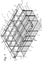
- Figure 1 shows a perspective view of an exemplary, non-limiting embodiment of a self-supporting steel skeleton 2 of a reusable modular building 1 according to the present invention.
- the self-supporting steel skeleton 2 shown in figure 1 has one storey, the skilled person will appreciate that it can also comprise two, three or more storeys.
- the self-supporting steel skeleton 2 shown in figure 1 comprises eight rectangular steel floor frames 3 that each comprise four elongated steel profiles 4 that are releasably coupled to each other with releasable coupling elements such as steel nuts and bolts.
- releasable coupling elements such as steel nuts and bolts.
- the self-supporting steel skeleton 2 further comprises eight rectangular steel roof frames 6 that each comprise four elongated steel profiles 4 that are releasably coupled to each other with releasable coupling elements.
- the self-supporting steel skeleton 2 comprises twenty steel supporting pillars 7 that are releasably connected under right angles with the elongated steel profiles 4 of both the rectangular steel floor frames 3 and the rectangular steel roof frames 6 so as to releasably interconnect the rectangular steel floor and roof frames.
- Each of the elongated steel profiles 4 of both the rectangular steel floor frames 3 and the rectangular steel roof frames 6 is provided with at least two tubular steel receiving members 8 that are arranged at opposite ends of each respective elongated steel profile 4.
- Each steel supporting pillar 7 is provided at its ends with at least one elongated steel protrusion 9 as will be discussed in more detail in relation to figure 2 .
- the elongated steel protrusions 9 can be at least one of rod-shaped and tubular-shaped.
- the tubular steel receiving members 8 and the elongated steel protrusions 9 are configured to establish a releasable tight-fitting coupling upon insertion of the elongated steel protrusions 9 into the tubular steel receiving members 8.
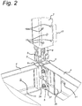
- Figure 2 provides a perspective view of an exemplary, non-limiting embodiment of end parts of two elongated steel profiles 4 of a rectangular steel floor frame 3 of the self-supporting steel skeleton 2 shown in figure 1 .
- the two elongated steel profiles 4 are releasably coupled using steel nuts 37 and bolts 38.
- Each elongated steel profile 4 is provided with a tubular receiving member 8 that is welded to the elongated steel profile 4 such that the longitudinal centerline of the elongated steel profile 4 is at a right angle with respect to the longitudinal centerline of the tubular steel receiving member 8.
- Figure 3A shows a top view of an exemplary, non-limiting embodiment of the elongated steel protrusions 9 that for example truss beams 34 as shown in figure 1 can be provided with.
- the tubular-shaped elongated steel protrusions 9 shown in figure 3A are welded to a supporting member that can be coupled to the truss beams.
- Figure 3B shows a first side view of the exemplary, non-limiting embodiment of the elongated steel protrusions 9 shown in figure 3A .
- the elongated steel protrusions 9 are divided in two types having different heights. This is also apparent from figure 3C that shows a second side view of the exemplary, non-limiting embodiment of the elongated steel protrusions shown in figure 3A .
- the skilled person will appreciate that different configurations of the elongated steel protrusions 9 can be envisaged.
- the elongated steel profiles 4 of both the rectangular floor 3 and roof 6 frames are obtained from cold rolled steel plates that are provided with a first predetermined hole pattern 10.
- the holes 11 of the first predetermined hole pattern 10, which can be seen in figure 1 and in greater detail in figure 2 are preferably provided by laser cutting but any other suitable technique can be used as well.
- the skilled person will appreciate that the same applies to the holes of the second, third and fourth predetermined hole patterns, respectively.
- the skilled person will appreciate that eventually the steel parts of the reusable modular building according to the invention, e.g. elongated steel profiles 4 and steel supporting pillars 7 will be galvanized.
- the holes 11 of the first predetermined hole pattern 10 are configured and arranged to receive releasable coupling elements to releasably couple adjacently arranged rectangular steel floor frames 3 and adjacently arranged rectangular steel roof frames 6.
- the diameter of the holes 11 and the dimensions of the elongated steel profiles 4 can be chosen depending on for example type of elongated profile, i.e. floor profile, roof profile, required strength and load capacity.
- the elongated steel profiles 4 can also be reinforced locally by providing steel reinforcement elements 36, one of which is shown as a rib or flange in figure 2 . In this way, the local strength and load capacity of the rectangular steel floor or roof frames in which the reinforced elongated steel profiles are applied is also enhanced.
- the releasable coupling elements that are receivable in the holes 11 can for example be steel nuts 37 and bolts 38. However, the skilled person will appreciate that any suitable releasable coupling elements can be used. As releasable coupling elements are used, there is no need to weld the respective rectangular steel floor frames 3 to one another or the rectangular steel roof frames 6 to one another. In this way, the self-supporting steel skeleton 2 can be erected much faster and with less cost. In addition, the reusability of the elongated steel profiles 4 is considerably enhanced. It is noted that the rectangular floor frames 3 and the rectangular roof frames 6 are provided in left, center and right versions.
- Figure 1 shows that the exemplary, non-limiting embodiment of the self-supporting steel skeleton 2 comprises two truss beams 34 for providing the required stability and load capacity of the self-supporting steel skeleton 2.
- Figure 1 also shows that shoring elements 35 are provided that are arranged to interconnect elongated steel profiles 4 of the rectangular steel roof frames 6 and the steel supporting pillars 7. In this way, the steel supporting pillars 7 and the rectangular steel roof frames 6 can be arranged perpendicular and level. Furthermore, a rigid self-supporting steel skeleton 2 is obtained.
- the shoring elements 35 shown in figure 1 have an adjustable length. The skilled person will appreciate that shoring elements having a fixed length can also be used. However, the use of shoring elements 35 having an adjustable length enables an even more convenient way of erecting the self-supporting steel skeleton 2 of the modular building 1 using the method according to the present invention.
- a steel supporting structure is provided that is arranged to enclose the periphery of the releasably coupled adjacently arranged rectangular steel floor frames 3.
- the steel supporting structure comprises Z-shaped steel supporting profiles 12.
- Figure 4 shows a side view of a part of a steel support pillar 7 combined with a cross-sectional view of an exemplary, non-limiting embodiment of a Z-shaped steel supporting profile 12 that is releasably coupled with an elongated steel profile 4 of a rectangular floor frame 3.
- the Z-shaped steel supporting profile 12 is arranged to receive and support a wall panel 13 that is releasably clamped to the steel supporting pillar 7.
- Each of the steel supporting profiles 12 is also provided with the first predetermined hole pattern 10 to releasably couple each of the steel supporting profiles 12 with elongated steel profiles 4 of the rectangular steel floor frames 3 that have a free side that faces away from the interior of the self-supporting steel skeleton 2.
- the steel supporting structure provides a slit in which wall panels 13 can at least partially be received.
- the steel supporting structure supports the wall panels 13 received in the slit.
- the wall panels 13 can be a glass panel or can comprise one of a window and a door.
- the steel supporting pillar 7 partially shown in figures 2 and 4 is provided with a second predetermined hole pattern 17.
- the holes 18 of the second predetermined hole pattern 17 are configured and arranged to receive releasable clamping mechanisms 19 that are used to releasably clamp wall panels 13 to the steel supporting pillars 7.
- the releasable clamping mechanism 19 is only partially visible in figure 4 and will be discussed in greater detail in relation to figure 5 .
- wall panel 13 is supported by the steel supporting structure 12 and is releasably clamped to the self-supporting steel skeleton 2. In this way, the wall panels 13 do not have a load-bearing function.
- the steel skeleton 2 is self-supporting it is possible to design the interior free space of the reusable modular building 1 as required by the specific use of the reusable modular building 1. For example, if the reusable modular building is used as a kitchen or restaurant facility, a large interior free space is desired.
- the steel supporting profiles 12 are provided with a third predetermined hole pattern (not shown).
- the holes of the third predetermined hole pattern are configured and arranged to drain rainwater.
- Figure 5 shows a top view of an exemplary, non-limiting embodiment of a releasable clamping mechanism 19 according to the present invention that is releasably coupled with two steel supporting pillars 7 to releasably clamp two wall panels 13 to the two steel supporting pillars.
- the releasable clamping mechanism 19 is arranged between two wall panels 13 to releasably clamp the two wall panels to a side of the steel supporting pillars 7 that faces away from the interior of the self-supporting steel skeleton 2.
- the skilled person will appreciate that by arranging the wall panels 13 outside of the steel supporting pillars, the formation of cold bridges can be prevented. As a result, this arrangement of the wall panels 13 significantly improves the thermal isolation of the modular building 1 according to the invention.
- the releasable clamping mechanism 19 it is possible to releasably clamp for example four wall panels 13 to the two steel supporting pillars 7.
- the releasable clamping mechanism 19 in the exemplary, non-limiting embodiment shown in figure 5 , comprises a steel supporting plate 20 that is provided with a first steel nut 21.
- the steel supporting plate 20 is connected with the two steel supporting pillars 7 such that the first steel nut 21 faces towards the two wall panels 13 that are releasably clamped to the steel supporting pillars.
- the releasable clamping mechanism 19 further comprises a steel threaded rod 22 that has a predetermined length that is determined by the thickness of the two wall panels 13 that are releasably clamped to the steel supporting pillars 7.
- a first end part of the steel threaded rod 22 is releasably connected with the first steel nut 21 of the steel supporting plate 20.
- a first resilient sealing member 23 is arranged in abutting contact with the two wall panels 13 and two releasable coupling elements that are used to releasably couple the steel supporting plate 20 to the steel supporting pillars 7.
- the releasable clamping mechanism 19 further comprises a steel retaining plate 24 that is provided with a hole that is configured and arranged to receive the steel threaded rod 22.
- the releasable clamping mechanism 19 also comprises a second resilient sealing member 25 that is arranged in abutting contact with both the steel retaining plate 24 and the two wall panels 13.
- the releasable clamping mechanism 19 furthermore comprises a second steel nut 26 that is releasably connected with the steel threaded rod 22 and arranged in abutting contact with the steel retaining plate 24 so as to keep the steel retaining plate 24 in abutting contact with the two wall panels 13 via the second resilient sealing member 25 to releasably clamp the two wall panels 13 against the steel supporting pillars 7.
- a very simple and robust releasable clamping mechanism 19 is provided that enables the reusable modular building 1 according to the invention to be assembled and disassembled very efficiently.
- the releasable clamping mechanism 19 also comprises a first elongated cover element 27 that is releasably connected with the steel retaining plate 24 via a snap connection.
- the first elongated cover element 27 prevents the releasable clamping mechanism 19 from being accessible from the outside. Furthermore, the first elongated cover element 27 prevents the releasable clamping mechanism 19 to be subjected to pollution from the environment in which the reusable modular building 1 according to the invention is used.
- the first elongated cover element 27 also provides an aesthetic finish for the exterior of the reusable modular building 1.
- the second steel nut 26 and the steel retaining plate 24 can be connected to each other so as to form one integrated component.
- At least a first spacer element can be connected with the steel threaded rod 22 and arranged between two adjacent wall panels 13 to keep them at a predefined distance with respect to each other. In this way, it is very easy to keep two adjacent wall panels 13 that need to be installed at the correct predefined distance with respect to each other. After installation of the wall panels 13, the at least first spacer element can either be left on the steel threaded rod 22 or be removed from it.
- Figure 1 shows that the rectangular steel floor frames 3 are provided with wooden reinforcement beams 28 that are arranged at right angles with respect to oppositely arranged elongated steel profiles 4 of the respective rectangular steel floor frames 3.
- the rectangular steel floor frames 3 that are provided with wooden reinforcement beams 28 have a higher strength and load capacity.
- the wooden reinforcement beams are not shown in figure 1 .
- wooden reinforcement beams 28 are applied in the rectangular steel floor and roof frames because this is advantageous with respect to for example mounting of installation modules inside the reusable modular building 1 and positioning of the rectangular steel floor 3 and roof 6 frames during erection of the modular building according to the invention.
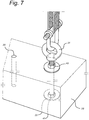
- Figure 7 shows a perspective view of an exemplary, non-limiting embodiment of a part of a wooden reinforcement beam 28 that is provided with two through holes 29.
- One through hole 29 is provided with an elongated steel element 30 that will be discussed in greater detail in relation to figures 6A and 6B .
- Figure 6A shows a side view of an exemplary, non-limiting embodiment of an elongated steel element 30 that is provided with threaded sections at its free ends. Each of these threaded sections is releasably coupled with a threaded tubular steel element 41, 42. Threaded tubular steel element 41 is coupled with a securing element 33 that, in use, confines the elongated steel element 30 to a through hole 29 in which it is arranged. This is shown in figure 7 .
- the other threaded steel tubular element 42 can be associated with a threaded steel ring-shaped element 31.
- Figure 7 shows that the threaded steel ring-shaped element 31 is a lifting eye that is associated with a sling that is arranged such that the wooden reinforcement beam 28 can be lifted for example to position a rectangular steel floor frame tightly against another rectangular steel floor frame.
- the lifting-eye shown in figure 7 can be replaced by a sealing element to cover the through hole 29 in the wooden reinforcement beam 28.
- Figure 6B shows a top view of the exemplary, non-limiting embodiment of the elongated steel element 30 shown in figure 6A .
- Figure 1 shows that the self-supporting steel skeleton 2 is provided with incrementing frames 39 that are releasably coupled to the rectangular steel roof frames 6 to provide the self-supporting steel skeleton 2 with a pitched roof.
- incrementing frames 39 are provided in left and right versions.
- the incrementing frames 39 are provided with wooden reinforcement beams 28.
- the incrementing frames that are provided with wooden reinforcement beams have a higher strength and load capacity. It is noted that instead of steel reinforcement beams, wooden reinforcement beams 28 are applied in the incrementing frames because this is advantageous with respect to for example mounting of roof panels and installation of air ducts of an air management system.
- FIG. 1 also shows a roof panel 40 that is releasably coupled to an incrementing frame 39 via the wooden reinforcement beams 28 that are associated with the respective incrementing frame 39.
- the roof panels 40 can comprise at least one of for example photovoltaic solar panels and solar collector panels of a solar water heater system.
- Figure 1 furthermore shows a steel eaves frame 14 that is arranged to enclose the periphery of the releasably coupled adjacently arranged rectangular steel roof frames 6.
- the steel eaves frame 14 comprises steel eaves profiles 15 each of which is arranged to support at least a first eaves panel 16.
- Each of the steel eaves profiles 15 is also provided with the first predetermined hole pattern 10 to releasably couple each of the steel eaves profiles 15 with elongated steel profiles 4 of the rectangular steel roof frames 6 that have a free side that faces away from the interior of the self-supporting steel skeleton 2. In this way, an edge of the roof is achieved that provides the impression as if it were freely floating with respect to the reusable modular building.
- facilities comprising at least one of a gutter and a lighting system can be provided behind the eaves panels 16.
Landscapes
- Engineering & Computer Science (AREA)
- Architecture (AREA)
- Civil Engineering (AREA)
- Structural Engineering (AREA)
- Physics & Mathematics (AREA)
- Electromagnetism (AREA)
- Conveying And Assembling Of Building Elements In Situ (AREA)
Claims (15)
- Une construction modulaire réutilisable (1) qui comprend en cours d'utilisation une carcasse en acier autoporteuse (2), comprenant :un nombre prédéterminé de cadres de base rectangulaires en acier (3) qui comprennent chacun des profilés en acier allongés (4) qui sont couplés de manière dissociable les uns aux autres par des éléments de couplage dissociables (5) ;un nombre prédéterminé de cadres de toit rectangulaires en acier (6) qui comprennent chacun des profilés en acier allongés qui sont couplés de manière dissociable les uns aux autres par des éléments de couplage dissociables ;un nombre prédéterminé de piliers supports en acier (7) qui sont connectés de manière dissociable à angle droit aux profilés en acier allongé de deux parmi le nombre prédéterminé de cadres de base rectangulaires en acier et le nombre prédéterminé de cadres de toit en acier de manière à interconnecter ledit nombre prédéterminé de cadres de base rectangulaires en acier et ledit nombre prédéterminé de cadres de toit en acier ;chaque profilé en acier allongé à la fois parmi le nombre prédéterminé de cadres de base rectangulaires en acier et le nombre prédéterminé de cadres de toit en acier étant pourvu d'au moins deux éléments récepteurs tubulaires en acier (8) qui sont disposés à des extrémités opposées de chaque profilé en acier allongé respectif,caractérisée en ce que chaque pilier support en acier du nombre prédéterminé de piliers supports en acier est pourvu à ses extrémités d'au moins une saillie en acier allongée (9), chacun desdits éléments récepteurs tubulaires en acier et chacune desdites saillies allongées en acier étant conçu pour établir un couplage dissociable à ajustement étroit sur insertion de ladite saillie en acier allongée dans ledit élément récepteur tubulaire en acier.
- La construction modulaire réutilisable (1) selon la revendication 1, dans laquelle chaque profilé en acier allongé (4) à la fois du nombre prédéterminé de cadres de base rectangulaires en acier (3) et du nombre prédéterminé de cadres de toit rectangulaires en acier (6) a une ligne centrale longitudinale qui est à angle droit par rapport à la ligne centrale longitudinale de chaque élément récepteur tubulaire en acier (8) avec lequel il est associé.
- La construction modulaire réutilisable (1) selon la revendication 1 ou 2, dans laquelle chaque profilé en acier allongé (4) à la fois du nombre prédéterminé de cadres de base rectangulaires en acier (3) et du nombre prédéterminé de cadres de toit en acier (6) est pourvu d'un premier modèle de trou prédéterminé(10), les trous (11) du premier modèle de trou prédéterminé étant conçus et disposés pour recevoir des éléments de couplage dissociables afin de coupler de manière dissociable des cadres de base rectangulaires en acier disposés de manière adjacente du nombre prédéterminé de cadres de base rectangulaire en acier et de cadres de toit rectangulaire en acier disposé de manière adjacente du nombre prédéterminé de cadres de toit rectangulaires en acier respectivement, étant prévue une structure support en acier qui est conçue pour renfermer la périphérie des cadres de base rectangulaires en acier (3) couplés de manière dissociable et disposés de manière adjacente du nombre prédéterminé de cadres de base rectangulaires en acier, la structure support en acier comprenant des profilés supports en acier (12) dont chacun a une forme de Z et est conçu pour recevoir et supporter au moins un premier panneau mural (13) d'un nombre prédéterminé de panneaux muraux, chacun des profilés supports en acier étant également pourvu du modèle de trou prédéterminé afin de coupler de manière dissociable chacun des profilés supports en acier avec des profilés en acier allongé (4) du nombre prédéterminé de cadres de base rectangulaires en acier (3) qui ont un côté libre qui est détourné de l'intérieur de la carcasse en acier autoporteuse (2).
- La construction modulaire réutilisable (1) selon la revendication 3, dans laquelle il est prévu un cadre d'avant-toit (14) qui est conçu pour renfermer la périphérie des cadres de toit rectangulaires en acier (6) disposés de manière adjacente du nombre prédéterminé de cadres de toit rectangulaires en acier, les avant-toits en acier comprenant des profilés d'avant-toit (15) dont chacun est conçu pour supporter au moins un premier panneau d'avant-toit (16) d'un nombre prédéterminé de panneaux d'avant-toit, chacun des profilés d'avant-toit étant aussi pourvu du premier modèle de trou prédéterminé (10) afin de coupler de manière dissociable chacun des profilés d'avant-toit en acier avec des profilés en acier allongés du nombre prédéterminé de cadres de toit rectangulaires en acier qui ont un côté libre qui est détourné de l'intérieur de la carcasse en acier autoporteuse (2).
- La construction modulaire réutilisable (1) selon la revendication 4, dans laquelle chaque pilier support en acier (7) du nombre prédéterminé de piliers supports en acier est pourvu d'un deuxième modèle de trou prédéterminé(17), les trous (18) du deuxième modèle de trou prédéterminé étant conçus et disposés pour recevoir des mécanismes de serrage dissociables (19) d'un nombre prédéterminé de mécanismes de serrage dissociables afin de serrer de manière dissociable le nombre prédéterminé de panneaux muraux (13) sur les piliers supports en acier, chaque mécanisme de serrage dissociable (19) étant disposé entre au moins deux panneaux muraux (13) du nombre prédéterminé de panneaux muraux afin de serrer de manière dissociable les au moins deux panneaux muraux sur un côté d'au moins un pilier support en acier (7) qui est détourné de l'intérieur de la carcasse en acier autoporteuse (2).
- La construction modulaire réutilisable (1) selon la revendication 5, dans laquelle chaque mécanisme de serrage dissociable (19) comprend
un plateau support en acier (20) pourvu d'un premier écrou en acier (21), le plateau support en acier étant connecté à au moins un pilier support en acier (7), de sorte que le premier écrou en acier est tourné vers les au moins deux panneaux muraux (13) à serrer de manière dissociable ;
une barre filetée en acier (22) ayant une longueur prédéterminée qui est déterminée par l'épaisseur des au moins deux panneaux muraux (13) qui doivent être serrés de manière dissociable,
une première pièce terminale de la barre filetée en acier étend, en cours d'utilisation du mécanisme de serrage dissociable, connectée de manière dissociable au premier écrou en acier (21) du plateau support en acier ;
au moins un premier élément d'étanchéité élastique (23) qui, en cours d'utilisation du mécanisme de serrage dissociable, est disposé en contact de butée avec au moins un des au moins deux panneaux muraux (13) à serrer de manière dissociable ;
un plateau de retenue en acier (24) qui est pourvu d'un trou qui, en cours d'utilisation du mécanisme de serrage dissociable, est conçu et disposé pour recevoir la barre filetée en acier (22) ;
au moins un second élément d'étanchéité élastique (25) qui, en cours d'utilisation du mécanisme de serrage dissociable, est disposé en contact de butée avec à la fois le plateau de retenue en acier (24) et au moins un des au moins deux panneaux muraux (13) à serrer de manière dissociable ;
un second écrou en acier (26) qui, en cours d'utilisation du mécanisme de serrage dissociable, est connecté de manière dissociable à la barre filetée en acier (22) et disposé de manière à être en contact de butée avec le plateau de retenue en acier (24) de manière à maintenir le plateau de retenue en acier en contact de butée avec les au moins deux panneaux muraux par l'intermédiaire de l'au moins un second élément d'étanchéité élastique afin de serrer de manière dissociable les au moins deux panneaux muraux contre les piliers supports en acier. - La construction modulaire réutilisable (1) selon la revendication 6, dans laquelle chaque mécanisme de serrage dissociable (19) comprend au moins un premier élément espaceur qui, en cours d'utilisation du mécanisme de serrage dissociable, est connecté à la barre filetée en acier (22) et disposé entre deux panneaux muraux adjacents pour les garder à une distance prédéfinie l'un par rapport à l'autre, chaque mécanisme de serrage dissociable (19) comprenant au moins un premier élément de recouvrement allongé (27) qui, en cours d'utilisation du mécanisme de serrage dissociable, est connecté de manière dissociable au plateau de retenue en acier (24) par l'intermédiaire d'une connexion à déclic.
- La construction modulaire réutilisable (1) selon l'une quelconque des revendications 4 à 7, dans laquelle les profilés supports en acier (22) sont pourvus d'un troisième modèle de trou prédéterminé, les trous du troisième modèle de trou prédéterminé étant conçus et disposés de manière à drainer l'eau de pluie.
- La construction modulaire réutilisable (1) selon l'une quelconque des revendications précédentes, dans laquelle au moins un cadre de base rectangulaire en acier (3) du nombre prédéterminé de cadres de base rectangulaires en acier et/ou au moins un cadre de toit rectangulaire en acier (6) du nombre prédéterminé de cadres de toit rectangulaires en acier est pourvu d'un nombre prédéterminé de poutres de renfort en bois (28), chaque poutre de renfort en bois du nombre prédéterminé de poutres de renfort en bois étant disposée à angle droit par rapport à des profilés en acier allongés (4) disposés à l'opposé de l'au moins un cadre de base rectangulaire en acier (3) respectif et/ou l'au moins un cadre de toit rectangulaire en acier (6), au moins une poutre de renfort en bois (28) du nombre prédéterminé de poutres de renfort en bois étant pourvue d'un nombre prédéterminé de trous traversants (29), au moins deux trous traversants du nombre prédéterminé de trous traversants étant chacun pourvu d'un élément en acier allongé (30), chacun des éléments en acier allongés étant pourvu de sections filetées à ses extrémités libres, chacune des sections filetées étant couplée de manière dissociable à un élément en acier tubulaire fileté (41,42), un élément en acier tubulaire fileté (41) étant couplé à un élément de blocage (33) qui, en cours d'utilisation de l'élément en acier allongé, est conçu pour confiner l'élément en acier allongé dans le trou traversant respectif (29) de la poutre de renfort en bois respective (28) dans laquelle il est disposé, l'autre élément tubulaire en acier fileté (42) étant, en cours d'utilisation de l'élément en acier allongé, associé à au moins un parmi un élément de forme annulaire fileté en acier (31) et un élément d'étanchéité.
- La construction modulaire réutilisable (1) selon l'une quelconque des revendications précédentes, dans laquelle il est prévu un nombre prédéterminé d'éléments d'étayage (35) qui, en cours d'utilisation de la construction modulaire réutilisable sont conçus pour interconnecter des profilés en acier (4) du nombre prédéterminé de cadres de toit rectangulaires en acier (6) et de piliers supports en acier (7) du nombre prédéterminé de piliers supports en acier, les éléments d'étayage (35) ayant une longueur ajustable.
- La construction modulaire réutilisable (1) selon l'une quelconque des revendications précédentes, dans laquelle les profilés en acier allongé (4) d'au moins un du nombre prédéterminé de cadres de base rectangulaires en acier (3) et du nombre prédéterminé de cadres de toit rectangulaires en acier (6) sont pourvus d'éléments de renfort en acier (36).
- La construction modulaire réutilisable (1) selon l'une quelconque des revendications précédentes, dans laquelle il est prévu un nombre prédéterminé de cadres d'incrémentation (39) qui, en cours d'utilisation de la construction modulaire réutilisable, sont couplés de manière dissociable à un nombre prédéterminé de cadres de toit rectangulaires en acier (6) pour équiper la carcasse en acier autoporteuse d'au moins une section de toit incliné.
- La construction modulaire réutilisable (1) selon la revendication 12, dans laquelle chaque cadre d'incrémentation (39) du nombre prédéterminé de cadres d'incrémentation est pourvu d'un nombre prédéterminé de poutres de renfort en bois (28).
- La construction modulaire réutilisable (1) selon la revendication 13, dans laquelle un nombre prédéterminé de panneaux de toit (40) est prévu et chaque panneau de toit du nombre prédéterminé de panneaux de toit est couplé de manière dissociable à au moins un cadre d'incrémentation (39) du nombre prédéterminé de cadres d'incrémentation par l'intermédiaire d'au moins une des poutres de renfort en bois (28) du nombre prédéterminé de poutres de renfort de toit qui est associé à l'au moins un cadre d'incrémentation respectif.
- La construction modulaire réutilisable (1) selon l'une quelconque des revendications précédentes, dans laquelle il est prévu un nombre prédéterminé de pièces d'un système de plafond dont chacune des pièces est pourvue d'un quatrième modèle de trou prédéterminé qui est aussi prévu pour chaque profilé en acier allongé (4) du nombre prédéterminé de cadres de toit rectangulaires en acier (6), les trous du quatrième modèle de trou prédéterminé étant conçus et disposés pour recevoir des éléments de couplage dissociables afin de coupler de manière dissociable au moins une première pièce du nombre prédéterminé de pièces du système de plafond à un premier cadre de toit rectangulaire en acier du nombre prédéterminé de cadres de toit rectangulaires en acier.
Applications Claiming Priority (2)
| Application Number | Priority Date | Filing Date | Title |
|---|---|---|---|
| NL2018353A NL2018353B1 (en) | 2017-02-10 | 2017-02-10 | A reusable modular building and a method for erecting the same |
| PCT/EP2018/053196 WO2018146202A1 (fr) | 2017-02-10 | 2018-02-08 | Bâtiment modulaire pouvant être réutilisé et son procédé de montage |
Publications (2)
| Publication Number | Publication Date |
|---|---|
| EP3580408A1 EP3580408A1 (fr) | 2019-12-18 |
| EP3580408B1 true EP3580408B1 (fr) | 2020-12-09 |
Family
ID=58159496
Family Applications (1)
| Application Number | Title | Priority Date | Filing Date |
|---|---|---|---|
| EP18709478.4A Active EP3580408B1 (fr) | 2017-02-10 | 2018-02-08 | Bâtiment modulaire pouvant être réutilisé et son procédé de montage |
Country Status (3)
| Country | Link |
|---|---|
| EP (1) | EP3580408B1 (fr) |
| NL (1) | NL2018353B1 (fr) |
| WO (1) | WO2018146202A1 (fr) |
Families Citing this family (2)
| Publication number | Priority date | Publication date | Assignee | Title |
|---|---|---|---|---|
| CN110397158B (zh) * | 2019-07-25 | 2021-03-30 | 中国建筑设计研究院有限公司 | 一种箱板钢结构装配式建筑系统 |
| CN118241878A (zh) * | 2024-05-07 | 2024-06-25 | 联合利华(广州)有限公司 | 一种钢结构管廊模块化安装方法 |
Family Cites Families (3)
| Publication number | Priority date | Publication date | Assignee | Title |
|---|---|---|---|---|
| CH531624A (de) * | 1970-08-19 | 1972-12-15 | Syma Intercontinental Sa | Baukonstruktion |
| DE3303190C2 (de) * | 1983-02-01 | 1985-05-23 | Octanorm-Vertriebs-GmbH für Bauelemente, 7024 Filderstadt | Bausatz zur Erstellung mobiler Bauten, insbesondere für Messe- und Ausstellungsbauten |
| US8726583B2 (en) * | 2010-04-13 | 2014-05-20 | University of South Florida (A Flordia Non-Profit Corporation) | Modular dwellings |
-
2017
- 2017-02-10 NL NL2018353A patent/NL2018353B1/en not_active IP Right Cessation
-
2018
- 2018-02-08 EP EP18709478.4A patent/EP3580408B1/fr active Active
- 2018-02-08 WO PCT/EP2018/053196 patent/WO2018146202A1/fr not_active Ceased
Non-Patent Citations (1)
| Title |
|---|
| None * |
Also Published As
| Publication number | Publication date |
|---|---|
| NL2018353B1 (en) | 2018-09-04 |
| EP3580408A1 (fr) | 2019-12-18 |
| WO2018146202A1 (fr) | 2018-08-16 |
Similar Documents
| Publication | Publication Date | Title |
|---|---|---|
| CA2017669C (fr) | Mur-rideau pour immeuble | |
| US5729950A (en) | All-metal reinforcing building frame | |
| FI112969B (fi) | Rakennuksen runko | |
| KR102310267B1 (ko) | 유닛블록 시스템 | |
| US9045894B2 (en) | Center-supported wall panel | |
| WO2016086481A1 (fr) | Structure de maison et procédé de construction associé | |
| JP3204340U (ja) | 生産管理プロセスのjグレード化されたエースシステムによるハイブリッド木造建築物 | |
| EP0485317B1 (fr) | Construction modulaire préfabriquée | |
| CN110965635B (zh) | 一种建筑的支撑结构及分层工业化建筑 | |
| US10240334B2 (en) | Z-arch building system | |
| US11339562B2 (en) | Area-covering structure module | |
| CN111411694A (zh) | 一体化装配式框架结构建筑体系 | |
| JP2016094787A (ja) | 外壁パネルの取付け構造および取付け方法 | |
| EP3580408A1 (fr) | Bâtiment modulaire pouvant être réutilisé et son procédé de montage | |
| EP4089244B1 (fr) | Immeuble modulaire de grande hauteur, extensible, démontable et réutilisable constitué d'éléments préfabriqués | |
| EP3551812B1 (fr) | Bâtiment à construction modulaire comprenant une poutre au sol | |
| US20190177975A1 (en) | Structural element | |
| JP2020084493A (ja) | 簡易建物 | |
| WO2012080561A1 (fr) | Procédé de fabrication de charpente de bâtiment, élément de charpente et charpente de bâtiment | |
| JP2023053521A (ja) | 建築物のリフォーム方法 | |
| WO1987000570A1 (fr) | Elements de construction | |
| RU138677U1 (ru) | Несущая панель | |
| JP3245443U (ja) | コンクリート一体形成型のドーム状建築物 | |
| US20240200338A1 (en) | Prefab Panel, Modular Facade, and Mounting Method Thereof | |
| CN211286803U (zh) | 多功能组合构件及由组合构件组合的移动平台、板房 |
Legal Events
| Date | Code | Title | Description |
|---|---|---|---|
| STAA | Information on the status of an ep patent application or granted ep patent |
Free format text: STATUS: UNKNOWN |
|
| STAA | Information on the status of an ep patent application or granted ep patent |
Free format text: STATUS: THE INTERNATIONAL PUBLICATION HAS BEEN MADE |
|
| PUAI | Public reference made under article 153(3) epc to a published international application that has entered the european phase |
Free format text: ORIGINAL CODE: 0009012 |
|
| STAA | Information on the status of an ep patent application or granted ep patent |
Free format text: STATUS: REQUEST FOR EXAMINATION WAS MADE |
|
| 17P | Request for examination filed |
Effective date: 20190909 |
|
| AK | Designated contracting states |
Kind code of ref document: A1 Designated state(s): AL AT BE BG CH CY CZ DE DK EE ES FI FR GB GR HR HU IE IS IT LI LT LU LV MC MK MT NL NO PL PT RO RS SE SI SK SM TR |
|
| AX | Request for extension of the european patent |
Extension state: BA ME |
|
| DAV | Request for validation of the european patent (deleted) | ||
| DAX | Request for extension of the european patent (deleted) | ||
| GRAP | Despatch of communication of intention to grant a patent |
Free format text: ORIGINAL CODE: EPIDOSNIGR1 |
|
| STAA | Information on the status of an ep patent application or granted ep patent |
Free format text: STATUS: GRANT OF PATENT IS INTENDED |
|
| INTG | Intention to grant announced |
Effective date: 20200727 |
|
| GRAS | Grant fee paid |
Free format text: ORIGINAL CODE: EPIDOSNIGR3 |
|
| GRAA | (expected) grant |
Free format text: ORIGINAL CODE: 0009210 |
|
| STAA | Information on the status of an ep patent application or granted ep patent |
Free format text: STATUS: THE PATENT HAS BEEN GRANTED |
|
| AK | Designated contracting states |
Kind code of ref document: B1 Designated state(s): AL AT BE BG CH CY CZ DE DK EE ES FI FR GB GR HR HU IE IS IT LI LT LU LV MC MK MT NL NO PL PT RO RS SE SI SK SM TR |
|
| REG | Reference to a national code |
Ref country code: GB Ref legal event code: FG4D |
|
| REG | Reference to a national code |
Ref country code: AT Ref legal event code: REF Ref document number: 1343606 Country of ref document: AT Kind code of ref document: T Effective date: 20201215 Ref country code: CH Ref legal event code: EP |
|
| REG | Reference to a national code |
Ref country code: DE Ref legal event code: R096 Ref document number: 602018010663 Country of ref document: DE |
|
| REG | Reference to a national code |
Ref country code: IE Ref legal event code: FG4D |
|
| REG | Reference to a national code |
Ref country code: NL Ref legal event code: FP |
|
| PG25 | Lapsed in a contracting state [announced via postgrant information from national office to epo] |
Ref country code: RS Free format text: LAPSE BECAUSE OF FAILURE TO SUBMIT A TRANSLATION OF THE DESCRIPTION OR TO PAY THE FEE WITHIN THE PRESCRIBED TIME-LIMIT Effective date: 20201209 Ref country code: FI Free format text: LAPSE BECAUSE OF FAILURE TO SUBMIT A TRANSLATION OF THE DESCRIPTION OR TO PAY THE FEE WITHIN THE PRESCRIBED TIME-LIMIT Effective date: 20201209 Ref country code: GR Free format text: LAPSE BECAUSE OF FAILURE TO SUBMIT A TRANSLATION OF THE DESCRIPTION OR TO PAY THE FEE WITHIN THE PRESCRIBED TIME-LIMIT Effective date: 20210310 Ref country code: NO Free format text: LAPSE BECAUSE OF FAILURE TO SUBMIT A TRANSLATION OF THE DESCRIPTION OR TO PAY THE FEE WITHIN THE PRESCRIBED TIME-LIMIT Effective date: 20210309 |
|
| REG | Reference to a national code |
Ref country code: AT Ref legal event code: MK05 Ref document number: 1343606 Country of ref document: AT Kind code of ref document: T Effective date: 20201209 |
|
| PG25 | Lapsed in a contracting state [announced via postgrant information from national office to epo] |
Ref country code: SE Free format text: LAPSE BECAUSE OF FAILURE TO SUBMIT A TRANSLATION OF THE DESCRIPTION OR TO PAY THE FEE WITHIN THE PRESCRIBED TIME-LIMIT Effective date: 20201209 Ref country code: BG Free format text: LAPSE BECAUSE OF FAILURE TO SUBMIT A TRANSLATION OF THE DESCRIPTION OR TO PAY THE FEE WITHIN THE PRESCRIBED TIME-LIMIT Effective date: 20210309 Ref country code: LV Free format text: LAPSE BECAUSE OF FAILURE TO SUBMIT A TRANSLATION OF THE DESCRIPTION OR TO PAY THE FEE WITHIN THE PRESCRIBED TIME-LIMIT Effective date: 20201209 |
|
| PG25 | Lapsed in a contracting state [announced via postgrant information from national office to epo] |
Ref country code: HR Free format text: LAPSE BECAUSE OF FAILURE TO SUBMIT A TRANSLATION OF THE DESCRIPTION OR TO PAY THE FEE WITHIN THE PRESCRIBED TIME-LIMIT Effective date: 20201209 |
|
| REG | Reference to a national code |
Ref country code: LT Ref legal event code: MG9D |
|
| PG25 | Lapsed in a contracting state [announced via postgrant information from national office to epo] |
Ref country code: SK Free format text: LAPSE BECAUSE OF FAILURE TO SUBMIT A TRANSLATION OF THE DESCRIPTION OR TO PAY THE FEE WITHIN THE PRESCRIBED TIME-LIMIT Effective date: 20201209 Ref country code: SM Free format text: LAPSE BECAUSE OF FAILURE TO SUBMIT A TRANSLATION OF THE DESCRIPTION OR TO PAY THE FEE WITHIN THE PRESCRIBED TIME-LIMIT Effective date: 20201209 Ref country code: EE Free format text: LAPSE BECAUSE OF FAILURE TO SUBMIT A TRANSLATION OF THE DESCRIPTION OR TO PAY THE FEE WITHIN THE PRESCRIBED TIME-LIMIT Effective date: 20201209 Ref country code: CZ Free format text: LAPSE BECAUSE OF FAILURE TO SUBMIT A TRANSLATION OF THE DESCRIPTION OR TO PAY THE FEE WITHIN THE PRESCRIBED TIME-LIMIT Effective date: 20201209 Ref country code: PT Free format text: LAPSE BECAUSE OF FAILURE TO SUBMIT A TRANSLATION OF THE DESCRIPTION OR TO PAY THE FEE WITHIN THE PRESCRIBED TIME-LIMIT Effective date: 20210409 Ref country code: RO Free format text: LAPSE BECAUSE OF FAILURE TO SUBMIT A TRANSLATION OF THE DESCRIPTION OR TO PAY THE FEE WITHIN THE PRESCRIBED TIME-LIMIT Effective date: 20201209 Ref country code: LT Free format text: LAPSE BECAUSE OF FAILURE TO SUBMIT A TRANSLATION OF THE DESCRIPTION OR TO PAY THE FEE WITHIN THE PRESCRIBED TIME-LIMIT Effective date: 20201209 |
|
| PG25 | Lapsed in a contracting state [announced via postgrant information from national office to epo] |
Ref country code: AT Free format text: LAPSE BECAUSE OF FAILURE TO SUBMIT A TRANSLATION OF THE DESCRIPTION OR TO PAY THE FEE WITHIN THE PRESCRIBED TIME-LIMIT Effective date: 20201209 Ref country code: PL Free format text: LAPSE BECAUSE OF FAILURE TO SUBMIT A TRANSLATION OF THE DESCRIPTION OR TO PAY THE FEE WITHIN THE PRESCRIBED TIME-LIMIT Effective date: 20201209 |
|
| REG | Reference to a national code |
Ref country code: DE Ref legal event code: R097 Ref document number: 602018010663 Country of ref document: DE |
|
| PG25 | Lapsed in a contracting state [announced via postgrant information from national office to epo] |
Ref country code: IS Free format text: LAPSE BECAUSE OF FAILURE TO SUBMIT A TRANSLATION OF THE DESCRIPTION OR TO PAY THE FEE WITHIN THE PRESCRIBED TIME-LIMIT Effective date: 20210409 Ref country code: MC Free format text: LAPSE BECAUSE OF FAILURE TO SUBMIT A TRANSLATION OF THE DESCRIPTION OR TO PAY THE FEE WITHIN THE PRESCRIBED TIME-LIMIT Effective date: 20201209 |
|
| PLBE | No opposition filed within time limit |
Free format text: ORIGINAL CODE: 0009261 |
|
| STAA | Information on the status of an ep patent application or granted ep patent |
Free format text: STATUS: NO OPPOSITION FILED WITHIN TIME LIMIT |
|
| PG25 | Lapsed in a contracting state [announced via postgrant information from national office to epo] |
Ref country code: AL Free format text: LAPSE BECAUSE OF FAILURE TO SUBMIT A TRANSLATION OF THE DESCRIPTION OR TO PAY THE FEE WITHIN THE PRESCRIBED TIME-LIMIT Effective date: 20201209 Ref country code: CH Free format text: LAPSE BECAUSE OF NON-PAYMENT OF DUE FEES Effective date: 20210228 Ref country code: LI Free format text: LAPSE BECAUSE OF NON-PAYMENT OF DUE FEES Effective date: 20210228 Ref country code: LU Free format text: LAPSE BECAUSE OF NON-PAYMENT OF DUE FEES Effective date: 20210208 Ref country code: IT Free format text: LAPSE BECAUSE OF FAILURE TO SUBMIT A TRANSLATION OF THE DESCRIPTION OR TO PAY THE FEE WITHIN THE PRESCRIBED TIME-LIMIT Effective date: 20201209 |
|
| 26N | No opposition filed |
Effective date: 20210910 |
|
| PG25 | Lapsed in a contracting state [announced via postgrant information from national office to epo] |
Ref country code: DK Free format text: LAPSE BECAUSE OF FAILURE TO SUBMIT A TRANSLATION OF THE DESCRIPTION OR TO PAY THE FEE WITHIN THE PRESCRIBED TIME-LIMIT Effective date: 20201209 Ref country code: SI Free format text: LAPSE BECAUSE OF FAILURE TO SUBMIT A TRANSLATION OF THE DESCRIPTION OR TO PAY THE FEE WITHIN THE PRESCRIBED TIME-LIMIT Effective date: 20201209 |
|
| PG25 | Lapsed in a contracting state [announced via postgrant information from national office to epo] |
Ref country code: IE Free format text: LAPSE BECAUSE OF NON-PAYMENT OF DUE FEES Effective date: 20210208 Ref country code: ES Free format text: LAPSE BECAUSE OF FAILURE TO SUBMIT A TRANSLATION OF THE DESCRIPTION OR TO PAY THE FEE WITHIN THE PRESCRIBED TIME-LIMIT Effective date: 20201209 |
|
| PG25 | Lapsed in a contracting state [announced via postgrant information from national office to epo] |
Ref country code: IS Free format text: LAPSE BECAUSE OF FAILURE TO SUBMIT A TRANSLATION OF THE DESCRIPTION OR TO PAY THE FEE WITHIN THE PRESCRIBED TIME-LIMIT Effective date: 20210409 |
|
| GBPC | Gb: european patent ceased through non-payment of renewal fee |
Effective date: 20220208 |
|
| PG25 | Lapsed in a contracting state [announced via postgrant information from national office to epo] |
Ref country code: GB Free format text: LAPSE BECAUSE OF NON-PAYMENT OF DUE FEES Effective date: 20220208 |
|
| PG25 | Lapsed in a contracting state [announced via postgrant information from national office to epo] |
Ref country code: CY Free format text: LAPSE BECAUSE OF FAILURE TO SUBMIT A TRANSLATION OF THE DESCRIPTION OR TO PAY THE FEE WITHIN THE PRESCRIBED TIME-LIMIT Effective date: 20201209 |
|
| PG25 | Lapsed in a contracting state [announced via postgrant information from national office to epo] |
Ref country code: HU Free format text: LAPSE BECAUSE OF FAILURE TO SUBMIT A TRANSLATION OF THE DESCRIPTION OR TO PAY THE FEE WITHIN THE PRESCRIBED TIME-LIMIT; INVALID AB INITIO Effective date: 20180208 |
|
| PG25 | Lapsed in a contracting state [announced via postgrant information from national office to epo] |
Ref country code: MK Free format text: LAPSE BECAUSE OF FAILURE TO SUBMIT A TRANSLATION OF THE DESCRIPTION OR TO PAY THE FEE WITHIN THE PRESCRIBED TIME-LIMIT Effective date: 20201209 |
|
| PG25 | Lapsed in a contracting state [announced via postgrant information from national office to epo] |
Ref country code: TR Free format text: LAPSE BECAUSE OF FAILURE TO SUBMIT A TRANSLATION OF THE DESCRIPTION OR TO PAY THE FEE WITHIN THE PRESCRIBED TIME-LIMIT Effective date: 20201209 |
|
| PG25 | Lapsed in a contracting state [announced via postgrant information from national office to epo] |
Ref country code: MT Free format text: LAPSE BECAUSE OF FAILURE TO SUBMIT A TRANSLATION OF THE DESCRIPTION OR TO PAY THE FEE WITHIN THE PRESCRIBED TIME-LIMIT Effective date: 20201209 |
|
| PGFP | Annual fee paid to national office [announced via postgrant information from national office to epo] |
Ref country code: NL Payment date: 20260206 Year of fee payment: 9 |
|
| PGFP | Annual fee paid to national office [announced via postgrant information from national office to epo] |
Ref country code: DE Payment date: 20260206 Year of fee payment: 9 |
|
| PGFP | Annual fee paid to national office [announced via postgrant information from national office to epo] |
Ref country code: BE Payment date: 20260206 Year of fee payment: 9 |
|
| PGFP | Annual fee paid to national office [announced via postgrant information from national office to epo] |
Ref country code: FR Payment date: 20260206 Year of fee payment: 9 |