EP3580481B1 - Bague de garniture, dispositif d'étanchéité, compresseur, système rotatif et procédé de détection de l'état d'usure - Google Patents
Bague de garniture, dispositif d'étanchéité, compresseur, système rotatif et procédé de détection de l'état d'usure Download PDFInfo
- Publication number
- EP3580481B1 EP3580481B1 EP18703711.4A EP18703711A EP3580481B1 EP 3580481 B1 EP3580481 B1 EP 3580481B1 EP 18703711 A EP18703711 A EP 18703711A EP 3580481 B1 EP3580481 B1 EP 3580481B1
- Authority
- EP
- European Patent Office
- Prior art keywords
- packing ring
- segment
- segments
- sealing device
- radial direction
- Prior art date
- Legal status (The legal status is an assumption and is not a legal conclusion. Google has not performed a legal analysis and makes no representation as to the accuracy of the status listed.)
- Active
Links
Images





Classifications
-
- F—MECHANICAL ENGINEERING; LIGHTING; HEATING; WEAPONS; BLASTING
- F16—ENGINEERING ELEMENTS AND UNITS; GENERAL MEASURES FOR PRODUCING AND MAINTAINING EFFECTIVE FUNCTIONING OF MACHINES OR INSTALLATIONS; THERMAL INSULATION IN GENERAL
- F16J—PISTONS; CYLINDERS; SEALINGS
- F16J15/00—Sealings
- F16J15/16—Sealings between relatively-moving surfaces
- F16J15/18—Sealings between relatively-moving surfaces with stuffing-boxes for elastic or plastic packings
- F16J15/24—Sealings between relatively-moving surfaces with stuffing-boxes for elastic or plastic packings with radially or tangentially compressed packing
-
- F—MECHANICAL ENGINEERING; LIGHTING; HEATING; WEAPONS; BLASTING
- F16—ENGINEERING ELEMENTS AND UNITS; GENERAL MEASURES FOR PRODUCING AND MAINTAINING EFFECTIVE FUNCTIONING OF MACHINES OR INSTALLATIONS; THERMAL INSULATION IN GENERAL
- F16J—PISTONS; CYLINDERS; SEALINGS
- F16J15/00—Sealings
- F16J15/16—Sealings between relatively-moving surfaces
- F16J15/26—Sealings between relatively-moving surfaces with stuffing-boxes for rigid sealing rings
-
- F—MECHANICAL ENGINEERING; LIGHTING; HEATING; WEAPONS; BLASTING
- F16—ENGINEERING ELEMENTS AND UNITS; GENERAL MEASURES FOR PRODUCING AND MAINTAINING EFFECTIVE FUNCTIONING OF MACHINES OR INSTALLATIONS; THERMAL INSULATION IN GENERAL
- F16J—PISTONS; CYLINDERS; SEALINGS
- F16J15/00—Sealings
- F16J15/16—Sealings between relatively-moving surfaces
- F16J15/32—Sealings between relatively-moving surfaces with elastic sealings, e.g. O-rings
- F16J15/3296—Arrangements for monitoring the condition or operation of elastic sealings; Arrangements for control of elastic sealings, e.g. of their geometry or stiffness
Definitions
- the present invention relates to a packing ring, a sealing device with at least one packing ring, a compressor with at least one packing ring and/or at least one sealing device, a rotary system with at least one packing ring and/or at least one sealing device and a method for detecting the wear condition of a packing ring and/or a sealing device.
- Sealing devices are used in many areas of technology to seal components that are static or moving relative to one another. The relative movement can be oscillating or rotating.
- Various types of sealing devices include, for example, individual seals or packings, which consist of several individual seals (also called packing rings) arranged one behind the other.
- One application for sealing devices is compressors.
- sealing devices can also be used in generators, as is the case, for example, in the EP 1 571 380 A1
- This document discloses, inter alia, a sealing device with brush seals, wherein the brush seals are arranged around a rotating shaft, which is intended to prevent a sealing oil and a gas used for cooling from coming into contact with each other.
- Sealing devices are used in various places in compressors.
- the compressor can be part of a larger system, for example, in the chemical industry.
- a specific application for sealing devices is the sealing of the piston rod of a compressor.
- the piston rod In a compressor, the piston rod is sealed multiple times to ensure that as little of the compressed process gas as possible escapes as leakage.
- a piston rod packing is typically used as a sealing device for sealing.
- a piston rod packing has several individual seals arranged one behind the other.
- a single seal can be constructed from several segments, each shaped like a circular ring.
- the segments rest on the piston rod with their inner circumferential surfaces and are pressed onto the piston rod on their outer circumferential surfaces by a common, circularly extending hose spring.
- a seal is known, for example, from the DE 10 2006 015 327 A1 known.
- the segments are made of polytetrafluoroethylene (PTFE), for example.
- Sealing rings divided into segments are sometimes equipped with an anti-twist device (also called locking or position lock).
- an anti-twist device also called locking or position lock.
- Such a sealing ring is, for example, DE 35 07 272 A1 known.
- the segments arranged around a piston rod do not form a closed circular ring. Rather, gaps (end gaps) form between the segments.
- Two individual seals can be arranged directly behind one another, with their segments offset from each other in such a way that the gaps of one individual seal are covered by the segments of the second individual seal.
- the pressure is determined indirectly by measuring the strain of a pressure-loaded component. By comparing the pressure with reference values, conclusions can then be drawn about wear. This approach is an indirect measurement that does not allow for precise conclusions about wear. It would be desirable to be able to directly measure the actual wear of individual components.
- the JP S54-117852 A a packing ring for a sealing device having at least two segments arranged around a common main axis, wherein the packing ring has at least one indicator means which indicates a position of at least one of the segments along a radial direction perpendicular to the main axis of the packing ring, wherein the indicator means has at least one indicator pin, wherein a hose spring is provided which applies a force to the segments in the radial direction.
- the packing ring according to the invention for a sealing device has at least two segments arranged around a common main axis X.
- the segments preferably have a ring-segment-like basic shape.
- the packing ring preferably has three segments.
- the segments When used as intended, the segments are in direct contact with an oscillating body, such as a piston rod.
- the movement of the body removes material from the inner circumferential surface of the segments, causing the segments to gradually wear out.
- Packing rings with segments can compensate for wear for a certain period of time.
- the segments are inserted into the packing ring when it is new. They are arranged circumferentially spaced from one another. This creates gaps between the segments. Due to continuous wear, the width of the segments gradually decreases in the radial direction, causing the segments as a whole to move radially toward the main axis X of the packing ring.
- the invention utilizes this property.
- the packing ring is characterized in that it comprises at least one indicator means which indicates a position of at least one of the segments along a radial direction perpendicular to the main axis of the packing ring.
- the segments gradually move toward the main axis X during their service life. Strictly speaking, it is in particular an outer peripheral surface of the segment that moves toward the main axis X.
- this movement of the outer peripheral surface is understood to mean a movement of the segment. Therefore, the indicator means indicates, in particular, the position of the outer peripheral surface or a part thereof along the radial direction.
- An indicator means in particular, means that enable an observer to detect the position or a change in the position of a segment in the radial direction.
- the indicator means is, in particular, a marking on the packing ring or an additional element.
- the indicator means comprises at least one indicator pin arranged on one of the segments.
- the indicator pin When wear occurs, the indicator pin gradually moves with the segment toward the oscillating or rotating body, so that the degree of wear of the segment is indicated by the progress or change in position of the indicator pin.
- the indicator pin is particularly preferably arranged such that it extends away from an outer circumferential surface of the segment in the radial direction R.
- the indicator pin has an inclined surface, wherein the inclined surface forms an angle ⁇ with the radial direction R, wherein ⁇ > 0°.
- the inclined surface preferably serves to interact with a sensor element, which will be described below.
- the inclined surface improves the accuracy of measuring the change in position of the indicator pin and thus the progress of wear.
- the indicator pin is connected to the segment.
- the indicator pin can be connected to the segment by a material fit, a force fit, or a form fit.
- the indicator pin can be connected to the segment as a single piece. In a single-piece design, the movement of the segment is very precisely mapped by the indicator pin, which leads to high accuracy in wear measurement.
- the indicator pin is connected to the segment as a form fit by means of a bolt.
- the indicator pin and the segment each have a bore through which a common bolt is inserted and/or pressed.
- the packing ring has a coil spring arranged in a common groove of the segments such that the coil spring applies a force to the segments in the radial direction R.
- the segments are thus pressed onto the oscillating body by a common coil spring.
- the segments wear to the same or a similar extent during normal use.
- the indicator pin is partially arranged in the groove so that it is held by the tubular spring.
- the indicator pin has a bore arranged in the groove and accommodating the tubular spring.
- the packing ring is preferably used in sealing devices that have one or more packing rings and optionally further rings, and particularly preferably in compressors, in particular as part of a piston rod packing.
- the further rings include, in particular, support rings, cover rings, and throttle rings. Throttle rings are used to reduce dynamic pressure components and come into only minimal contact with the oscillating piston rod, so that hardly any wear is to be expected here. Nevertheless, a wear measurement according to the invention can also be provided for throttle rings.
- support rings which are only secondarily subject to wear because they have a radial gap to the piston rod on the inner diameter and their primary function is the mechanical support of the sealing rings in the direction of the main axis X.
- a packing ring can also be used, as shown in DE 10 2006 015 327 A1 or from AT 505 550 B1 These are packing rings composed of cover and sealing segments, so that no additional cover or sealing ring is required to achieve the sealing function. Even when using such packing rings, throttle and/or support rings can be used in a piston rod packing and equipped with a wear measurement device according to the invention. However, in a preferred embodiment, only the wear of the packing ring or the wear of the packing rings contained in the piston rod packing is measured.
- the sealing device comprises a housing and at least one packing ring.
- the packing ring has at least two segments arranged around a common main axis X.
- the sealing device is characterized in that it comprises a sensor device that detects a position of at least one of the segments along a radial direction R perpendicular to the main axis X of the packing ring. In particular, the position of an outer peripheral surface of at least one of the segments is detected along the radial direction.
- the segments move in the radial direction R towards the main axis X due to wear.
- the sensor device makes it possible to detect the position of the segment and thus the wear condition.
- the sealing device has at least one packing ring according to the invention in accordance with the above statements.
- the sensor device interacts with the indicator means and/or the packing ring. In this way, the sensor device can determine the position of a segment and thus its wear condition.
- the sensor device interacts with the outer peripheral surface of at least one segment of the packing ring.
- the sensor device has at least one sensor element.
- the sensor element is directed towards the outer peripheral surface. In this way, the position of the outer peripheral surface and any change in this position are directly detected. This allows a movement of the outer peripheral surface and thus a movement of the associated segment to be detected.
- the sensor element is arranged at an angle ⁇ to the radial direction R, where 0° ⁇ ⁇ ⁇ 90°.
- the sensor element is preferably a cylindrical body with a cylinder axis Z or has a cylindrical basic shape with a cylinder axis Z.
- the cylinder axis Z is preferably arranged at the angle ⁇ to the radial direction R.
- ⁇ 90°. Due to the 90° arrangement, the sensor element is preferably arranged parallel to the main axis X.
- the sealing device therefore has a compact design, since its extension in the radial direction R does not increase or only increases slightly.
- the sensor element is preferably a distance-measuring sensor element.
- the sensor element measures a distance between itself and the packing ring, in particular a segment of the packing ring, furthermore in particular an outer circumferential surface of a segment of the packing ring, and/or between itself and the indicator means, in particular the indicator pin.
- the distance measurement preferably takes place in the radial direction R or in a direction parallel to the main axis X of the packing ring.
- the sensor element is an eddy current sensor.
- a coil of the eddy current sensor generates a magnetic field, causing eddy currents to develop in a conductive object located within the magnetic field. These eddy currents also generate a field that counteracts the magnetic field of the coil. This change is detected by the eddy current sensor. The detected signal varies depending on the distance from the conductive object.
- Eddy current sensors are small in size and can therefore be easily integrated into a sealing device. Furthermore, eddy current sensors are suitable for use in areas with high temperatures, high pressures, and contaminants.
- the sensor element is an optical sensor element.
- An optical sensor element uses electromagnetic radiation of at least one wavelength to perform its function.
- the optical sensor element is particularly preferably a confocal sensor.
- a confocal sensor a so-called beam path is generated using multiple lenses.
- White light is split into monochromatic light waves.
- the individual light waves focus at different distances from the lens arrangement.
- the confocal sensor detects the wavelength of the light wave reflected by an object. This allows the distance to the object to be determined.
- Confocal sensors have a resolution of up to 10 nm. This allows for high accuracy in measuring the degree of wear. High accuracy allows for better utilization of the service life of a packing ring.
- the housing of the sealing device comprises at least two chamber discs, with at least one packing ring arranged between two adjacent chamber discs.
- additional rings can also be arranged between the chamber discs, and in particular between two adjacent chamber discs.
- a cover ring, a packing ring, and a support ring are arranged one behind the other between two adjacent chamber discs.
- wear is preferably measured on the cover ring and the sealing ring, since these rings generally have the described circumferential clearance between the segments, and the segments therefore move toward the main axis X by advancing in the radial direction R when wear occurs on the inner diameter.
- At least one chamber disc has a receptacle for an indicator pin of a packing ring.
- a receptacle is particularly useful when the indicator pin extends radially away from the packing ring. In this case, the provision of a receptacle prevents the chamber disc from having to be enlarged overall.
- the indicator pin is guided in the receptacle. This ensures that the indicator pin can only move in one desired direction, particularly in the radial direction. Movement in the axial direction of the sealing device and/or in the circumferential direction is preferably prevented.
- the receptacle is preferably arranged at a radial distance from the packing ring.
- At least one chamber disc has a bore for accommodating a sensor element and/or a sensor cable.
- a common bore can also be provided in several adjacent chamber discs. The bore, in particular, allows the sensor element to be positioned close to the packing ring and/or the indicator means. This ensures accurate measurement, especially in conjunction with a confocal sensor.
- the sensor element is preferably arranged in and/or on a chamber disc by means of a screw connection.
- the sensor element has an external thread and is screwed into a chamber disc. This ensures that no relative movement occurs between the sensor element and the chamber disc. This increases the precision of the measurement.
- At least one sealing element is arranged between the chamber discs in the area of the bore.
- At least one chamber disc has a viewing element.
- a viewing element is transparent in at least one wavelength range and in particular in the visible light range (380 nm to 780 nm).
- the viewing element is preferably made of quartz glass.
- the viewing element enables viewing of the packing ring and/or the indicator means from outside the interior in which the packing ring is located.
- a sensor element can be arranged such that the viewing element is located between the sensor and the packing ring. In this way, the sensor element is not exposed, or is only exposed to a limited extent, the conditions in the interior of the housing.
- the sensor element is then preferably a confocal sensor.
- a compressor according to the invention comprises a piston rod and at least one packing ring according to the above embodiments and/or at least one sealing device according to the above embodiments.
- the compressor according to the invention is preferably used for compressing gases, in particular process gases in industrial plants.
- a rotary system according to the invention comprises a shaft rotatable about a shaft axis W and at least one packing ring according to the above embodiments and/or at least one sealing device according to the above embodiments.
- the packing ring is arranged on the shaft and seals, for example, at a transition from a lubricated to a non-lubricated area.
- the rotary system according to the invention is preferably used in blowers, fans, or pumps.
- the position of a segment changes as it gradually wears on an inner circumferential surface.
- the method according to the invention determines the position of a segment relative to a starting position directly or indirectly.
- the determined position provides information about the extent to which the segment, and with it the packing ring, is worn.
- the position of the segment or indicator device is recorded as a function of time. This function enables continuous monitoring of the wear condition of the packing ring.
- a final value for the position of the segment or indicator is determined at the beginning of the process.
- the determined position is compared with the final value.
- a warning is triggered when the final value is reached or exceeded.
- the final value determines when a packing ring is considered worn, i.e., when the packing ring has reached the end of its service life.
- the final value can also be set to a portion of the lifetime value, for example, 80%. This maintains a safety margin.
- the position of the segment or the indicator means is determined via a distance measurement.
- a distance measurement is advantageous because distance measurements can be performed with little effort and the distance measurement devices are robust.
- the distance measurement is preferably performed between the sensor element and the indicator means and/or between the sensor element and a segment of the packing ring, in particular an outer peripheral surface of the segment.
- the position of the segment or indicator is determined using an optical measurement or an eddy current measurement.
- An optical measurement uses electromagnetic radiation of at least one wavelength to perform the measurement.
- Optical measurements can also be used to measure non-conductive materials.
- FIG. 1 A packing ring 10 with three segments 20 is shown.
- the three segments 20 have a common inner circumferential surface 24.
- the segments 20 rest with their inner circumferential surface 24, for example, against a piston rod (not shown here) and seal there.
- the segments 20 are arranged around a common main axis X.
- a gap 15 is provided in the circumferential direction.
- the segments 20 wear in the area of the inner circumferential surface 24.
- the segments 20 gradually move towards the main axis X. Due to this movement, the gaps 15 gradually become smaller until the segments 20 lie directly against each other. The segments 20 can then no longer move in the direction of the main axis X, so that further wear on the inner circumferential surface 24 of the packing ring 10 will cause it to leak.
- two packing rings 10 can be arranged one behind the other in the direction of the main axis X.
- the packing rings 10 are rotated relative to each other in the circumferential direction so that each gap 15 of one packing ring 10 is covered by the segment 20 of the other packing ring 10.
- the packing ring 10 has three support elements 16.
- the support elements 16 and the segments 20 are arranged alternately in the circumferential direction of the packing ring 10.
- the support elements 16 and the segments 20 share a common outer peripheral surface 22.
- the outer peripheral surface 22 has the shape of a cylindrical surface.
- a groove 14 is provided in the area of the outer circumferential surface 22. In the circumferential direction, the groove 14 extends over the entire outer circumferential surface 22.
- a coil spring 12 is arranged in the groove 14. The coil spring 12 exerts a force directed along the main axis X. This causes the segments 20 to be pressed onto the piston rod (not shown) during proper use.
- the coil spring 12 is shown schematically in all figures.
- the packing ring 10 has an indicator means 30 in the form of an indicator pin 32.
- the indicator pin 32 is arranged on a segment 20 in the region of the outer peripheral surface 22.
- the indicator pin 32 has a cylindrical basic shape and an inclined surface 34.
- the indicator pin 34 is arranged such that the longitudinal axis of the cylindrical basic shape extends in the radial direction R.
- the radial direction R forms a right angle with the main axis X.
- the Figures 2 and 3 show a packing ring 10 according to a second embodiment. Compared to the embodiment of Figure 1 The segments 20 and the support elements 16 differ in their shape. The invention is applicable to a variety of different, known packing rings 10.
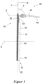
- a sensor element 42 with a cylinder axis Z is shown.
- the cylinder axis Z is parallel to the main axis X of the packing ring 10.
- the sensor element 42 is aligned with the inclined surface 34 of the indicator pin 32.
- the inclined surface 34 is arranged at an angle ⁇ to a radial direction R.
- the angle ⁇ is approximately 7°.
- the cylinder axis Z is arranged at an angle ⁇ to the radial direction R.
- the angle ⁇ is 90°.
- the sensor element 42 determines its distance from the inclined surface 34 of the indicator pin 32. With increasing wear, the segments 20 move towards the main axis X.
- the indicator pin 32 is connected to a segment 20. Therefore, the indicator pin 32 also moves towards the main axis X due to wear.
- the distance between the sensor element 42 and the inclined surface 34 gradually increases, with the distance along the cylinder axis Z being measured in particular.
- the continuous increase in the distance is detected by the sensor element 42 and can be displayed and/or processed on an evaluation device (not shown here).
- the sensor element is connected to the evaluation device by means of a sensor line 44.
- FIG 4 A packing ring 10 with two segments 20 is shown schematically.
- the segments 20 are designed as half-shells and arranged around a common main axis X.
- a sensor element 42 with a cylinder axis Z is aligned with one of the segments 20.
- the sensor element 42 is a cylindrical body.
- Figure 4 shown packing ring 10 with the sensor element 42 is part of a sealing device according to the invention, which in Figure 4 is not fully represented.
- the cylinder axis Z corresponds to the radial axis R.
- the angle ⁇ between the cylinder axis Z and the radial direction R is 0° in this arrangement.
- a sensor line 44 is arranged on the sensor element 42.
- the sensor line 44 leads to an evaluation device (not shown here).
- the sensor element 42 is an eddy current sensor, i.e., a distance-measuring sensor element 42.
- the sensor element 42 continuously detects the distance between the sensor element 42 and the segment 20. Due to wear, the segments 20 move in the direction of the main axis X, whereby the distance between the sensor element 42 and the segment 20 increases. The wear can be determined from the distance.
- Figure 5 shows a further embodiment of a packing ring 10.
- the packing ring 10 has four segments 20 arranged around a common main axis X.
- An indicator pin 32 is arranged on each of two opposite segments 20.
- the indicator pins 32 extend in a common radial direction R.
- Each indicator pin 32 is positively secured to a segment 20 by a respective bolt 36.
- the indicator pins 32 each have an inclined surface 34.
- a sensor device 40 has two sensor elements 42. Each sensor element 42 is assigned to an indicator pin 32.
- the sensor elements 42 each have a cylindrical shape with a cylinder axis Z.
- the sensor elements 42 are each connected to an evaluation device 46 via a sensor line 44.
- the evaluation device 46 receives the signals from the sensor elements 42 and displays them to a user. Additionally, a final value for the position of the indicator pins 32 is stored in the evaluation device 46. If this final value is exceeded for one of the two indicator pins 32, a warning message is issued by the evaluation device 46.
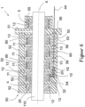
- Figure 6 shows a sealing device 1 with a housing 50 and a packing ring 10 according to the invention arranged in the housing 50.
- the sealing device 1 is a piston rod packing for sealing a piston rod 110.
- Three additional packing rings 60 are also arranged in the housing 50.
- the packing ring 10 has a plurality of segments 20 arranged around a common main axis X.
- the housing 50 has five chamber discs 52. All packing rings 10, 60 are each arranged between a cover ring 11 and a support ring 13. Each chamber disc 52 has an interior in which either a packing ring 10, 60 with the associated cover ring 11 and support ring 13 or a throttle ring 4 is arranged. A chamber disc 52 is arranged on a first side of a flange 51. On a second side of the flange 51, opposite the first side, there is an attachment 55 in which a leakage gas seal 5 is arranged.
- the packing rings 10, 60, the throttle ring 4, the cover rings 11, and individual rings of the leakage gas seal 5 are each subjected to a force directed along the main axis X by a hose spring 12. As a result, these rings rest against the piston rod 110.
- the packing ring 10 has an indicator pin 32.
- the chamber disc 52 of the packing ring 10 has a receptacle 54 for the indicator pin 32.
- the indicator pin 32 has an inclined surface 34. Due to wear of the segments 20 of the packing ring 10, the indicator pin 32 moves in the receptacle 54 toward the main axis X.
- a sensor element 42 is aligned with the inclined surface 34 of the indicator pin 32. The sensor element 42 continuously determines the distance to the inclined surface 34.
- the sensor element 42 is screwed into a chamber disc 52.
- the sensor element 42 is an eddy current sensor.
- the sensor element 42 is connected to an evaluation device (not shown here) via the sensor line 44.
- Four chamber discs 52 and the flange 51 have a common bore 53 for the sensor element 42 and a sensor line 44.
- a sealing element 56 is arranged in the area of the bore 53 between each two chamber discs 52 or one chamber disc 52 and the flange 51. The sealing elements 56 prevent leaks from occurring due to the bore 53.
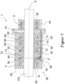
- FIG. 7 A further embodiment of a sealing device 1 according to the invention is shown.
- the sealing device 1 has a housing 50 with five chamber discs 52, a flange 51, and an attachment 55 through which a piston rod 110 extends.
- the chamber discs 52 each have an interior space containing either a packing ring 10, 60 together with a support ring 13 or a throttle ring 4.
- the packing rings 10, 60 are of conventional design.
- a leakage gas seal 5 is arranged in the interior of the cap 55.
- the sealing device 1 has an optical sensor element 42 in the form of a confocal sensor.
- the chamber disc 52 of the packing ring 10 has a viewing element 58 radially outside the packing ring 10.
- the viewing element 58 is a quartz glass disc.
- the sensor element 42 is arranged radially outside the viewing element 58.
- the viewing element 58 is located between the packing ring 10 and the sensor element 42.
- the packing ring 10 has a plurality of segments 20 arranged around a common main axis X.
- the confocal sensor has a cylindrical basic shape. It is designed in a 90° configuration. With this configuration, the measuring direction is perpendicular to a cylinder axis Z of the cylindrical basic shape. The cylinder axis Z is arranged parallel to the main axis X. The measuring direction of the sensor element 42 is thus parallel to a radial direction R of the packing ring 10.
- the sensor element 42 generates a beam path by which the distance between the sensor element 42 and a segment 20 of the packing ring 10 is determined. If the segment 20 moves toward the main axis X due to wear, the distance increases. In this way, the wear of the segment 20 can be determined.
- the sensor element 42 is connected to an evaluation device (not shown here) via the sensor line 44.
- Figure 8 shows a compressor 100 according to the invention with a sealing device 1.
- the compressor 100 has a compressor housing 101 in which a piston rod 110 is arranged. During intended use, the piston rod 110 performs an oscillating movement and is driven by a crank (not shown).
- the compressor 100 has a compression chamber 102 in which process gas can be compressed.
- a piston 112 is arranged in the compression chamber 102.
- the piston 112 is connected to the piston rod 110.
- the compressor 100 has a first intermediate piece 104, a second intermediate piece 106, and a crank chamber 108 along the main axis X.
- the piston rod 110 extends from the compression chamber 102 into the crank chamber 108.
- Piston rod 110 and piston 112 are shown in two states.
- a first state the piston 112 is at a first reversal point.
- the speed of the piston is zero.
- the process gas occupies the largest possible volume in the compression chamber 102.
- a second state the piston 112 is at a second reversal point.
- the process gas has been compressed and occupies a smaller volume.
- Figure 8 an inlet and an outlet for the process gas.
- the sealing device 1 is arranged between the compression chamber 102 and the first intermediate piece 104.
- the sealing device 1 is designed as a piston rod packing.
- the sealing device 1 has a housing 50 in which a packing ring 10 is arranged.
- the packing ring 10 has an indicator pin 32 that extends radially outward from the packing ring 10.
- the packing ring 10, together with a support ring 13, is arranged between two chamber discs 52 of the housing 50.
- the compressor 100 has a sensor device 40.
- the sensor device has a sensor element 42, a sensor line 44, and an evaluation device 46.
- the sensor element 42 is arranged in the housing 50.
- the sensor line 44 connects the sensor element 42 to the evaluation device. 46.
- the sensor element 42 is an eddy current sensor.
- the housing 50 has a bore 53 for the sensor element 42 and a portion of the sensor line 44.
- An intermediate seal 105 is arranged between the first intermediate piece 104 and the second intermediate piece 106.
- the intermediate seal 105 provides additional protection and prevents process gas that has entered the first intermediate piece 104 despite the sealing device 1 from entering the second intermediate piece 106.
- An oil scraper seal 107 is arranged between the second intermediate piece 106 and the crank chamber 108. The oil scraper seal 107 ensures that as little lubricant as possible, especially oil, from the crank chamber 108 enters the second intermediate piece 106.
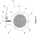
- FIG 9 A rotary system 70 according to the invention is shown.
- the rotary system 70 has a shaft 72 with a shaft axis W.
- the shaft 72 is rotatably mounted about the shaft axis W.
- a packing ring 10 is arranged on the shaft 72.
- the packing ring 10 has three segments 20.
- the segments 20 are arranged around a common main axis X, which in the embodiment shown corresponds to the shaft axis W.
- An indicator pin 32 is arranged on one segment 20.
- the indicator pin 32 extends in the radial direction R away from the segment 20.
- a sensor element 42 with a cylinder axis Z is aligned with the indicator pin 32.
- Optional components of the rotary system 70 not shown include a housing, bearings for the shaft and a drive device.
- Figure 10 shows a diagram of a wear measurement.
- the ordinate axis indicates the measurement duration in hours.
- the abscissa axis indicates the signal strength of the sensor element in volts.
- the image shows the signal from an eddy current sensor directed at the inclined surface of the indicator pin attached to a segment.
- the segment is part of a packing ring in a piston rod seal of a reciprocating compressor.
- a rapidly wearing PTFE was used as the material for the segments to minimize the test time until the seal ring is completely worn.
- the packing ring seals a dynamic pressure from 30 bar to 80 bar. Nitrogen was used as the sealing medium.
Landscapes
- Engineering & Computer Science (AREA)
- General Engineering & Computer Science (AREA)
- Mechanical Engineering (AREA)
- Sealing Devices (AREA)
- Compressor (AREA)
Claims (13)
- Bague de garniture (10) pour un dispositif d'étanchéité (1) comprenant au moins deux segments (20) qui sont agencés autour d'un axe principal (X) commun, la bague de garniture (10) comprenant au moins un moyen d'indication (30) qui indique une position d'au moins un des segments (20) le long d'une direction radiale (R) perpendiculaire à l'axe principal (X) de la bague de garniture (10), le moyen d'indication (30) comprenant au moins une tige d'indication (32) qui est agencée au segment (20) et la tige d'indication (32) étant reliée au segment (20), un ressort tubulaire (12) étant fourni, lequel ressort tubulaire est agencé dans une rainure commune (14) des segments (20) de sorte que le ressort tubulaire (12) applique une force sur les segments (20) dans la direction radiale R.
- Bague de garniture (10) selon la revendication 1, caractérisée en ce que la tige d'indication (32) est agencée de telle manière qu'elle s'étend à partir d'une surface périphérique extérieure (22) du segment (20) dans la direction radiale (R).
- Bague de garniture (10) selon la revendication 1 ou 2, caractérisée en ce que la tige d'indication (32) comprend une surface inclinée (34), la surface inclinée (34) formant un angle (α) avec la direction radiale (R) avec α > 0°.
- Dispositif d'étanchéité (1) comprenant un boîtier (50) et au moins une bague de garniture (10) selon l'une quelconque des revendications précédentes.
- Dispositif d'étanchéité (1) selon la revendication 4, caractérisé en ce que le dispositif d'étanchéité (1) comprend un dispositif de détection (40) qui détecte une position d'au moins un des segments (20) le long d'une direction radiale (R) perpendiculaire à l'axe principal (X) de la bague de garniture (10).
- Dispositif d'étanchéité (1) selon la revendication 4 ou 5, caractérisé en ce que le dispositif de détection (40) comprend au moins un élément de détection (42).
- Dispositif d'étanchéité (1) selon l'une quelconque des revendications 4 à 6, caractérisé en ce que le boîtier (50) comprend au moins deux disques de chambre (52), au moins une bague de garniture (10) étant agencée entre deux disques de chambre (52) agencés l'un à côté de l'autre.
- Compresseur (100) comprenant une tige de piston (110) et au moins une bague de garniture (10) selon l'une quelconque des revendications 1 à 3 et/ou au moins un dispositif d'étanchéité (1) selon l'une quelconque des revendications 4 à 7.
- Système rotatif (70) comprenant un arbre (72) pouvant tourner autour d'un axe d'arbre (W) et au moins une bague de garniture (10) selon l'une quelconque des revendications 1 à 3 et/ou au moins un dispositif d'étanchéité (1) selon l'une quelconque des revendications 4 à 7.
- Procédé de détection de l'état d'usure d'une bague de garniture (10) selon l'une quelconque des revendications 1 à 3 et/ou d'un dispositif d'étanchéité (1) selon l'une quelconque des revendications 4 à 7, comprenant les étapes ci-dessous consistant à :- agencer un dispositif de détection (40) de sorte qu'il interagisse avec un segment (20) et/ou un moyen d'indication (30) agencé à un segment (20) ;- définir une position de départ du segment (20) ou du moyen d'indication (30) le long d'une direction radiale (R) ;- déterminer au moins une position du segment (20) ou du moyen d'indication (30) le long de la direction radiale (R) du segment (20) par rapport à la position de départ au moyen du dispositif de détection (40).
- Procédé selon la revendication 10, caractérisé en ce que la position du segment (20) ou du dispositif d'indication (30) est enregistrée en fonction du temps.
- Procédé selon la revendication 10 ou 11, caractérisé en ce qu'une valeur finale pour la position du segment (20) ou du moyen d'indication (30) est définie au début du procédé, en ce que la position déterminée est comparée à la valeur finale et en ce qu'un message d'avertissement est émis en cas d'atteinte ou de dépassement de la valeur finale.
- Procédé selon l'une quelconque des revendications 10 à 12, caractérisé en ce que la détermination de la position du segment (20) ou du moyen d'indication (30) résulte d'une mesure de distance.
Applications Claiming Priority (2)
| Application Number | Priority Date | Filing Date | Title |
|---|---|---|---|
| DE102017202148.9A DE102017202148A1 (de) | 2017-02-10 | 2017-02-10 | Packungsring, dichtungsvorrichtung, kompressor, rotatorisches system und verfahren zum erfassen des verschleisszustandes |
| PCT/EP2018/051948 WO2018145922A1 (fr) | 2017-02-10 | 2018-01-26 | Bague de garniture, dispositif d'étanchéité, compresseur, système rotatif et procédé de détection de l'état d'usure |
Publications (3)
| Publication Number | Publication Date |
|---|---|
| EP3580481A1 EP3580481A1 (fr) | 2019-12-18 |
| EP3580481B1 true EP3580481B1 (fr) | 2025-06-04 |
| EP3580481C0 EP3580481C0 (fr) | 2025-06-04 |
Family
ID=61187281
Family Applications (1)
| Application Number | Title | Priority Date | Filing Date |
|---|---|---|---|
| EP18703711.4A Active EP3580481B1 (fr) | 2017-02-10 | 2018-01-26 | Bague de garniture, dispositif d'étanchéité, compresseur, système rotatif et procédé de détection de l'état d'usure |
Country Status (4)
| Country | Link |
|---|---|
| US (2) | US11852242B2 (fr) |
| EP (1) | EP3580481B1 (fr) |
| DE (1) | DE102017202148A1 (fr) |
| WO (1) | WO2018145922A1 (fr) |
Families Citing this family (2)
| Publication number | Priority date | Publication date | Assignee | Title |
|---|---|---|---|---|
| CN113834401B (zh) * | 2020-06-23 | 2023-08-22 | 中国航发商用航空发动机有限责任公司 | 级间封严环安装到位判定方法 |
| DE102024124435A1 (de) | 2024-08-27 | 2026-03-05 | Basf Se | Dichtring, Anordnung und Verfahren zur Erkennung von Verschleiß an einem Kolbenverdichter |
Citations (4)
| Publication number | Priority date | Publication date | Assignee | Title |
|---|---|---|---|---|
| CH196493A (de) * | 1937-07-17 | 1938-03-15 | Escher Wyss Maschf Ag | Abdichtungsvorrichtung für sich drehende oder hin- und herbewegende Maschinenteile. |
| US2208976A (en) * | 1938-06-29 | 1940-07-23 | Koppers Co Inc | Rod or shaft packing |
| US20080136115A1 (en) * | 2006-12-07 | 2008-06-12 | Jerry Wayne Johnson | Floating sealing ring |
| WO2016022136A1 (fr) * | 2014-08-08 | 2016-02-11 | Siemens Energy, Inc. | Système d'optimisation de logement de joint d'étanchéité inter-étage dans un moteur à turbine à gaz |
Family Cites Families (26)
| Publication number | Priority date | Publication date | Assignee | Title |
|---|---|---|---|---|
| US2731285A (en) * | 1953-03-31 | 1956-01-17 | France Packing Company | Segmental metallic packing rings |
| US3235274A (en) * | 1962-12-14 | 1966-02-15 | Garrett Corp | Shaft seal |
| US3305241A (en) * | 1965-10-19 | 1967-02-21 | Cooper Bessemer Corp | Packing ring structure |
| GB1239414A (fr) | 1968-07-27 | 1971-07-14 | ||
| US3836158A (en) * | 1973-03-07 | 1974-09-17 | Gulf Oil Corp | Packing ring |
| US4046387A (en) * | 1976-09-16 | 1977-09-06 | Lee Dalton I | Device for indicating the presence of a gasket |
| JPS54117852A (en) | 1978-03-03 | 1979-09-12 | Toshiba Corp | Device for sealing main shaft |
| US4258944A (en) * | 1978-11-09 | 1981-03-31 | Wendel Ion L | Split slip nut and seal assembly for plumbing trap |
| US4413529A (en) * | 1981-09-17 | 1983-11-08 | Dresser Industries, Inc. | Adjustably keyed pressure gauge construction |
| GB8319550D0 (en) * | 1983-07-20 | 1983-08-24 | Grange Packing Ltd | Seal wear indicator |
| DE3507272C2 (de) * | 1985-03-01 | 1994-03-31 | Espey Gustav Gmbh & Co Kg | Mehrteiliger Dichtring |
| US6615639B1 (en) * | 1992-02-25 | 2003-09-09 | Ralph Heinzen | Self monitoring static seal |
| AU2884497A (en) * | 1997-06-02 | 1998-12-21 | Maschinenfabrik Sulzer-Burckhardt Ag | Sealing element for dry-running systems and the use thereof |
| DE19723804C2 (de) | 1997-06-06 | 2003-10-30 | Neuman & Esser Gmbh & Co Kg Ma | Vorrichtung zur Ermittlung des Druckes im Arbeitsraum von Hubkolbenmaschinen |
| US6286837B1 (en) * | 1999-08-24 | 2001-09-11 | Delaware Capital Formation, Inc. | Compressor piston rod packing ring set |
| US6692006B2 (en) * | 2001-10-15 | 2004-02-17 | Stein Seal Company | High-pressure film-riding seals for rotating shafts |
| JPWO2004044465A1 (ja) * | 2002-11-13 | 2006-03-16 | 株式会社東芝 | 回転電機 |
| DE10343498A1 (de) * | 2003-02-07 | 2005-05-04 | Univ Leipzig | Verfahren zur Feststellung wenigstens eines Zustandsparameters eines Dichtungssystems sowie Dichtungssystem |
| US7144477B2 (en) * | 2003-12-15 | 2006-12-05 | Voith Paper Patent Gmbh | Wear indicator for seal strip in a suction box of a paper machine |
| CA2581508A1 (fr) * | 2004-10-22 | 2006-04-27 | Burckhardt Compression Ag | Dispositif de garniture de tige de piston fonctionnant a sec et procede pour rendre etanche une tige de piston avec un dispositif de garniture de tige de piston fonctionnant a sec |
| DE102006015327B9 (de) | 2006-03-30 | 2010-06-17 | Stasskol Kolbenstangendichtungen Gmbh | Kolbenstangendichtring |
| AT505550B1 (de) | 2007-10-31 | 2009-02-15 | Hoerbiger Kompressortech Hold | Mehrteiliger packungsring |
| US9004495B2 (en) * | 2008-09-15 | 2015-04-14 | Stein Seal Company | Segmented intershaft seal assembly |
| AT506811B1 (de) | 2008-09-25 | 2009-12-15 | Hoerbiger Kompressortech Hold | Druckpackung aus verdrehgesicherten packungsringen mit spritzgegossenen segmenten |
| DE202012000209U1 (de) * | 2012-01-11 | 2013-04-22 | Gapi Technische Produkte Gmbh | Fluiddrehdurchführung |
| WO2015097014A1 (fr) | 2013-12-23 | 2015-07-02 | Burckhardt Compression Ag | Bague d'étanchéité |
-
2017
- 2017-02-10 DE DE102017202148.9A patent/DE102017202148A1/de active Pending
-
2018
- 2018-01-26 WO PCT/EP2018/051948 patent/WO2018145922A1/fr not_active Ceased
- 2018-01-26 US US16/482,406 patent/US11852242B2/en active Active
- 2018-01-26 EP EP18703711.4A patent/EP3580481B1/fr active Active
-
2022
- 2022-07-26 US US17/873,718 patent/US20220373091A1/en active Pending
Patent Citations (4)
| Publication number | Priority date | Publication date | Assignee | Title |
|---|---|---|---|---|
| CH196493A (de) * | 1937-07-17 | 1938-03-15 | Escher Wyss Maschf Ag | Abdichtungsvorrichtung für sich drehende oder hin- und herbewegende Maschinenteile. |
| US2208976A (en) * | 1938-06-29 | 1940-07-23 | Koppers Co Inc | Rod or shaft packing |
| US20080136115A1 (en) * | 2006-12-07 | 2008-06-12 | Jerry Wayne Johnson | Floating sealing ring |
| WO2016022136A1 (fr) * | 2014-08-08 | 2016-02-11 | Siemens Energy, Inc. | Système d'optimisation de logement de joint d'étanchéité inter-étage dans un moteur à turbine à gaz |
Also Published As
| Publication number | Publication date |
|---|---|
| EP3580481A1 (fr) | 2019-12-18 |
| US11852242B2 (en) | 2023-12-26 |
| WO2018145922A1 (fr) | 2018-08-16 |
| DE102017202148A1 (de) | 2018-08-16 |
| US20220373091A1 (en) | 2022-11-24 |
| EP3580481C0 (fr) | 2025-06-04 |
| US20190360596A1 (en) | 2019-11-28 |
Similar Documents
| Publication | Publication Date | Title |
|---|---|---|
| EP3698073B1 (fr) | Garniture d'étanchéité à anneau glissant pour assurer l'étanchéité d'un conduit et/ou d'un espace de guidage de fluide et procédé de surveillance de l'usure d'une garniture d'étanchéité à anneau glissant | |
| DE69110141T2 (de) | Diagnostikvorrichtung und -verfahren für die Kolbenringabnutzung. | |
| EP0156136B1 (fr) | Joint de haute pression | |
| WO2014206393A2 (fr) | Joint d'arbre radial | |
| WO2006042866A1 (fr) | Dispositif de garniture de tige de piston fonctionnant a sec et procede pour rendre etanche une tige de piston avec un dispositif de garniture de tige de piston fonctionnant a sec | |
| DE102012212633A1 (de) | Hydraulikzylinder, insbesondere für eine Kupplungsbetätigungseinrichtung in einem Kraftfahrzeug | |
| CH697962B1 (de) | Innengehäuse für eine Rotationsmaschine, Rotationsmaschine und Verfahren zur Regelung eines Masses eines Mantelrings in einer Rotationsmaschine. | |
| DE102020111386A1 (de) | Zustandserfassung an Exzenterschneckenpumpen | |
| DE2947937C2 (de) | Verfahren und Vorrichtung zur Bestimmung von Wälzlagerschäden | |
| EP4022202B1 (fr) | Procédé et dispositif de surveillance d'état d'une garniture haute pression d'un compresseur à piston | |
| WO2008089800A1 (fr) | Garniture mécanique d'étanchéité avec fonction de surveillance | |
| EP3580481B1 (fr) | Bague de garniture, dispositif d'étanchéité, compresseur, système rotatif et procédé de détection de l'état d'usure | |
| DE10024759B4 (de) | Anordnungsaufbau für einen Analysesensor für das Betriebsverhalten der Kolben einer Brennkraftmaschine und Verfahren zur Durchführung | |
| AT510444B1 (de) | Einrichtung zur kurbelwinkelaufgelösten vermessung | |
| DE102006028294A1 (de) | Radiallageranordnung mit einer diese zentrierenden Spannringanordnung | |
| EP1006271A2 (fr) | Procédé et dispositif pour la détermination du statut d'une pièce mobile dans le cylindre d'un moteur à combustion interne | |
| DE102019101049B4 (de) | Verfahren zum Bestimmen des Verschleißes eines Lagers | |
| DE4010769C2 (fr) | ||
| DE10239949B4 (de) | Verfahren zum Überwachen von Gleitlagern eines Kurbeltriebes einer Kolbenmaschine mit wenigstens einem Zylinder | |
| DE102019123067A1 (de) | Fetteigenschaftsmessvorrichtung und Fetteigenschaftsmessverfahren | |
| DE19925540C2 (de) | Prüfeinrichtung für Radial- und Axialwellendichtungen | |
| DE102013220429A1 (de) | Gleitringdichtungsanordnung mit optischer Überwachungseinrichtung und Verfahren zum Überwachen eines Dichtspaltes einer Gleitringdichtungsanordnung | |
| EP3473898B1 (fr) | Garniture mécanique d'étanchéité destinée à étanchéifier un canal et / ou un espace guidant un fluide | |
| DE8912621U1 (de) | Lagerung | |
| DE102020100453B4 (de) | Verfahren zum Bestimmen des Verschleißes eines Lagers |
Legal Events
| Date | Code | Title | Description |
|---|---|---|---|
| STAA | Information on the status of an ep patent application or granted ep patent |
Free format text: STATUS: UNKNOWN |
|
| STAA | Information on the status of an ep patent application or granted ep patent |
Free format text: STATUS: THE INTERNATIONAL PUBLICATION HAS BEEN MADE |
|
| PUAI | Public reference made under article 153(3) epc to a published international application that has entered the european phase |
Free format text: ORIGINAL CODE: 0009012 |
|
| STAA | Information on the status of an ep patent application or granted ep patent |
Free format text: STATUS: REQUEST FOR EXAMINATION WAS MADE |
|
| 17P | Request for examination filed |
Effective date: 20190813 |
|
| AK | Designated contracting states |
Kind code of ref document: A1 Designated state(s): AL AT BE BG CH CY CZ DE DK EE ES FI FR GB GR HR HU IE IS IT LI LT LU LV MC MK MT NL NO PL PT RO RS SE SI SK SM TR |
|
| AX | Request for extension of the european patent |
Extension state: BA ME |
|
| DAV | Request for validation of the european patent (deleted) | ||
| DAX | Request for extension of the european patent (deleted) | ||
| STAA | Information on the status of an ep patent application or granted ep patent |
Free format text: STATUS: EXAMINATION IS IN PROGRESS |
|
| 17Q | First examination report despatched |
Effective date: 20220222 |
|
| GRAP | Despatch of communication of intention to grant a patent |
Free format text: ORIGINAL CODE: EPIDOSNIGR1 |
|
| STAA | Information on the status of an ep patent application or granted ep patent |
Free format text: STATUS: GRANT OF PATENT IS INTENDED |
|
| INTG | Intention to grant announced |
Effective date: 20241112 |
|
| GRAJ | Information related to disapproval of communication of intention to grant by the applicant or resumption of examination proceedings by the epo deleted |
Free format text: ORIGINAL CODE: EPIDOSDIGR1 |
|
| STAA | Information on the status of an ep patent application or granted ep patent |
Free format text: STATUS: EXAMINATION IS IN PROGRESS |
|
| GRAP | Despatch of communication of intention to grant a patent |
Free format text: ORIGINAL CODE: EPIDOSNIGR1 |
|
| STAA | Information on the status of an ep patent application or granted ep patent |
Free format text: STATUS: GRANT OF PATENT IS INTENDED |
|
| INTC | Intention to grant announced (deleted) | ||
| INTG | Intention to grant announced |
Effective date: 20250129 |
|
| RIN1 | Information on inventor provided before grant (corrected) |
Inventor name: MORAWA, UWE Inventor name: KRANERT, DENNIS Inventor name: LANGELA, MARC |
|
| GRAS | Grant fee paid |
Free format text: ORIGINAL CODE: EPIDOSNIGR3 |
|
| GRAA | (expected) grant |
Free format text: ORIGINAL CODE: 0009210 |
|
| STAA | Information on the status of an ep patent application or granted ep patent |
Free format text: STATUS: THE PATENT HAS BEEN GRANTED |
|
| AK | Designated contracting states |
Kind code of ref document: B1 Designated state(s): AL AT BE BG CH CY CZ DE DK EE ES FI FR GB GR HR HU IE IS IT LI LT LU LV MC MK MT NL NO PL PT RO RS SE SI SK SM TR |
|
| REG | Reference to a national code |
Ref country code: GB Ref legal event code: FG4D Free format text: NOT ENGLISH |
|
| REG | Reference to a national code |
Ref country code: CH Ref legal event code: EP |
|
| REG | Reference to a national code |
Ref country code: DE Ref legal event code: R096 Ref document number: 502018015854 Country of ref document: DE |
|
| REG | Reference to a national code |
Ref country code: IE Ref legal event code: FG4D Free format text: LANGUAGE OF EP DOCUMENT: GERMAN |
|
| U01 | Request for unitary effect filed |
Effective date: 20250623 |
|
| U07 | Unitary effect registered |
Designated state(s): AT BE BG DE DK EE FI FR IT LT LU LV MT NL PT RO SE SI Effective date: 20250701 |
|
| PG25 | Lapsed in a contracting state [announced via postgrant information from national office to epo] |
Ref country code: ES Free format text: LAPSE BECAUSE OF FAILURE TO SUBMIT A TRANSLATION OF THE DESCRIPTION OR TO PAY THE FEE WITHIN THE PRESCRIBED TIME-LIMIT Effective date: 20250604 |
|
| PG25 | Lapsed in a contracting state [announced via postgrant information from national office to epo] |
Ref country code: NO Free format text: LAPSE BECAUSE OF FAILURE TO SUBMIT A TRANSLATION OF THE DESCRIPTION OR TO PAY THE FEE WITHIN THE PRESCRIBED TIME-LIMIT Effective date: 20250904 Ref country code: GR Free format text: LAPSE BECAUSE OF FAILURE TO SUBMIT A TRANSLATION OF THE DESCRIPTION OR TO PAY THE FEE WITHIN THE PRESCRIBED TIME-LIMIT Effective date: 20250905 |
|
| PG25 | Lapsed in a contracting state [announced via postgrant information from national office to epo] |
Ref country code: PL Free format text: LAPSE BECAUSE OF FAILURE TO SUBMIT A TRANSLATION OF THE DESCRIPTION OR TO PAY THE FEE WITHIN THE PRESCRIBED TIME-LIMIT Effective date: 20250604 |
|
| PG25 | Lapsed in a contracting state [announced via postgrant information from national office to epo] |
Ref country code: HR Free format text: LAPSE BECAUSE OF FAILURE TO SUBMIT A TRANSLATION OF THE DESCRIPTION OR TO PAY THE FEE WITHIN THE PRESCRIBED TIME-LIMIT Effective date: 20250604 |
|
| PG25 | Lapsed in a contracting state [announced via postgrant information from national office to epo] |
Ref country code: RS Free format text: LAPSE BECAUSE OF FAILURE TO SUBMIT A TRANSLATION OF THE DESCRIPTION OR TO PAY THE FEE WITHIN THE PRESCRIBED TIME-LIMIT Effective date: 20250904 |
|
| PG25 | Lapsed in a contracting state [announced via postgrant information from national office to epo] |
Ref country code: IS Free format text: LAPSE BECAUSE OF FAILURE TO SUBMIT A TRANSLATION OF THE DESCRIPTION OR TO PAY THE FEE WITHIN THE PRESCRIBED TIME-LIMIT Effective date: 20251004 |
|
| PG25 | Lapsed in a contracting state [announced via postgrant information from national office to epo] |
Ref country code: SM Free format text: LAPSE BECAUSE OF FAILURE TO SUBMIT A TRANSLATION OF THE DESCRIPTION OR TO PAY THE FEE WITHIN THE PRESCRIBED TIME-LIMIT Effective date: 20250604 |
|
| PG25 | Lapsed in a contracting state [announced via postgrant information from national office to epo] |
Ref country code: CZ Free format text: LAPSE BECAUSE OF FAILURE TO SUBMIT A TRANSLATION OF THE DESCRIPTION OR TO PAY THE FEE WITHIN THE PRESCRIBED TIME-LIMIT Effective date: 20250604 |
|
| PG25 | Lapsed in a contracting state [announced via postgrant information from national office to epo] |
Ref country code: SK Free format text: LAPSE BECAUSE OF FAILURE TO SUBMIT A TRANSLATION OF THE DESCRIPTION OR TO PAY THE FEE WITHIN THE PRESCRIBED TIME-LIMIT Effective date: 20250604 |
|
| U20 | Renewal fee for the european patent with unitary effect paid |
Year of fee payment: 9 Effective date: 20260116 |
|
| PLBE | No opposition filed within time limit |
Free format text: ORIGINAL CODE: 0009261 |
|
| STAA | Information on the status of an ep patent application or granted ep patent |
Free format text: STATUS: NO OPPOSITION FILED WITHIN TIME LIMIT |
|
| REG | Reference to a national code |
Ref country code: CH Ref legal event code: L10 Free format text: ST27 STATUS EVENT CODE: U-0-0-L10-L00 (AS PROVIDED BY THE NATIONAL OFFICE) Effective date: 20260416 |