EP3581010B1 - Système de mesure de marchandises pour un véhicule de travail doté de rouleaux agencés en quinconce - Google Patents
Système de mesure de marchandises pour un véhicule de travail doté de rouleaux agencés en quinconce Download PDFInfo
- Publication number
- EP3581010B1 EP3581010B1 EP19172404.6A EP19172404A EP3581010B1 EP 3581010 B1 EP3581010 B1 EP 3581010B1 EP 19172404 A EP19172404 A EP 19172404A EP 3581010 B1 EP3581010 B1 EP 3581010B1
- Authority
- EP
- European Patent Office
- Prior art keywords
- metering
- commodity
- work vehicle
- rollers
- roller
- Prior art date
- Legal status (The legal status is an assumption and is not a legal conclusion. Google has not performed a legal analysis and makes no representation as to the accuracy of the status listed.)
- Active
Links
Images



Classifications
-
- A—HUMAN NECESSITIES
- A01—AGRICULTURE; FORESTRY; ANIMAL HUSBANDRY; HUNTING; TRAPPING; FISHING
- A01C—PLANTING; SOWING; FERTILISING
- A01C7/00—Sowing
- A01C7/08—Broadcast seeders; Seeders depositing seeds in rows
- A01C7/081—Seeders depositing seeds in rows using pneumatic means
-
- A—HUMAN NECESSITIES
- A01—AGRICULTURE; FORESTRY; ANIMAL HUSBANDRY; HUNTING; TRAPPING; FISHING
- A01C—PLANTING; SOWING; FERTILISING
- A01C7/00—Sowing
- A01C7/20—Parts of seeders for conducting and depositing seed
-
- A—HUMAN NECESSITIES
- A01—AGRICULTURE; FORESTRY; ANIMAL HUSBANDRY; HUNTING; TRAPPING; FISHING
- A01C—PLANTING; SOWING; FERTILISING
- A01C21/00—Methods of fertilising, sowing or planting
- A01C21/002—Apparatus for sowing fertiliser; Fertiliser drill
-
- A—HUMAN NECESSITIES
- A01—AGRICULTURE; FORESTRY; ANIMAL HUSBANDRY; HUNTING; TRAPPING; FISHING
- A01C—PLANTING; SOWING; FERTILISING
- A01C7/00—Sowing
- A01C7/08—Broadcast seeders; Seeders depositing seeds in rows
- A01C7/10—Devices for adjusting the seed-box ; Regulation of machines for depositing quantities at intervals
- A01C7/102—Regulating or controlling the seed rate
-
- A—HUMAN NECESSITIES
- A01—AGRICULTURE; FORESTRY; ANIMAL HUSBANDRY; HUNTING; TRAPPING; FISHING
- A01C—PLANTING; SOWING; FERTILISING
- A01C7/00—Sowing
- A01C7/08—Broadcast seeders; Seeders depositing seeds in rows
- A01C7/12—Seeders with feeding wheels
- A01C7/123—Housings for feed rollers or wheels
- A01C7/124—Housings for feed rollers or wheels with top delivery of the seeds
-
- A—HUMAN NECESSITIES
- A01—AGRICULTURE; FORESTRY; ANIMAL HUSBANDRY; HUNTING; TRAPPING; FISHING
- A01C—PLANTING; SOWING; FERTILISING
- A01C7/00—Sowing
- A01C7/08—Broadcast seeders; Seeders depositing seeds in rows
- A01C7/12—Seeders with feeding wheels
- A01C7/126—Stubbed rollers or wheels
-
- A—HUMAN NECESSITIES
- A01—AGRICULTURE; FORESTRY; ANIMAL HUSBANDRY; HUNTING; TRAPPING; FISHING
- A01C—PLANTING; SOWING; FERTILISING
- A01C7/00—Sowing
- A01C7/08—Broadcast seeders; Seeders depositing seeds in rows
- A01C7/12—Seeders with feeding wheels
- A01C7/127—Cell rollers, wheels, discs or belts
-
- A—HUMAN NECESSITIES
- A01—AGRICULTURE; FORESTRY; ANIMAL HUSBANDRY; HUNTING; TRAPPING; FISHING
- A01C—PLANTING; SOWING; FERTILISING
- A01C7/00—Sowing
- A01C7/20—Parts of seeders for conducting and depositing seed
- A01C7/206—Seed pipes
Definitions
- This disclosure relates to work vehicles and implements, and more specifically, to a commodity metering system for a work vehicle with metering rollers that are disposed in a staggered arrangement.
- Seeding work vehicles such as air carts/seeders and other seeding devices, are configured for applying seed, fertilizer, and/or other particulate commodities to a field.
- the work vehicle may be operatively connected to tilling equipment for applying the commodity under the surface of the soil.
- Seeding work vehicles typically include one or more tanks and a metering system that meters out a predetermined quantity of the commodity from the tank as the work vehicle moves across the field.
- the metering system may include a plurality of metering elements, such as metering rollers that are configured to meter out the commodity from the tank.
- US2017/0055436 discloses a system with a plurality of metering rollers which are all operated simultaneously by a single drive shaft.
- This disclosure provides an improved commodity metering system and/or delivery system for a work vehicle. This disclosure also provides methods for operating the same.
- lists with elements that are separated by conjunctive terms (e.g., "and") and that are also preceded by the phrase "one or more of” or "at least one of” indicate configurations or arrangements that potentially include individual elements of the list, or any combination thereof.
- “at least one of A, B, and C” or “one or more of A, B, and C” indicates the possibilities of only A, only B, only C, or any combination of two or more of A, B, and C (e.g., A and B; B and C; A and C; or A, B, and C).
- forward refers to a direction corresponding to the direction of travel of the work vehicle
- aft refers to an opposing direction
- fore-aft axis may also reference an axis extending in fore and aft directions.
- lateral axis may refer to an axis that is perpendicular to the fore-aft axis and extends in a horizontal plane; that is, a plane containing both the fore-aft and lateral axes.
- vertical refers to an axis or a direction orthogonal to the horizontal plane containing the fore-aft and lateral axes.
- the work vehicle includes a metering system with a plurality of metering elements.
- the metering elements comprises metering rollers.
- the metering rollers may actuate (rotate) independent of each other and at variable output speeds in some embodiments.
- the work vehicle may also include a control system configured to control the actuation of the metering rollers individually and independently.
- the metering rollers are spaced apart and arranged substantially parallel to each other.
- the rollers may be substantially parallel to the primary axis of the work vehicle (i.e., parallel to the direction of travel).
- the rollers are disposed in a staggered arrangement.
- the rollers are staggered vertically and horizontally.
- the rollers may be arranged into rows that are spaced apart vertically and that are offset horizontally.
- the work vehicle includes a delivery system with a plurality of tubes. Air may move through the tubes.
- the tubes may receive commodity that is metered out from the metering rollers, and the commodity may travel along the tubes within the airstream toward a row unit for planting in the soil.
- At least part of the tubes may be arranged substantially parallel to each other (e.g., parallel to the primary axis of the work vehicle) and substantially parallel to the metering rollers.
- the tubes of the delivery system may be disposed in a staggered arrangement.
- the tubes may be staggered vertically and horizontally in some embodiments. For example, a part of the tubes may be arranged into rows that are spaced apart vertically and that are offset horizontally.
- the metering rollers may be housed in a common housing.
- the housing may define an inlet that receives the commodity from a commodity container.
- the housing may also define a plurality of outlets. Commodity that enters the housing through the inlet may be metered by the metering rollers and provided to respective ones of the outlets.
- the outlets may provide the metered commodity to respective ones of the tubes of the delivery system. Then, the tubes may deliver the commodity to the row units for planting in the soil.
- the work vehicle may provide the commodity to the soil in a controlled and accurate manner.
- the arrangement of the metering rollers and/or the tubes of the delivery system may be compact and well-organized.
- Figure 1 illustrates a work vehicle 100 according to example embodiments of the present disclosure.
- the work vehicle 100 may be towed by another vehicle, such as a tractor (not shown).
- the work vehicle 100 of the present disclosure may be a self-propelled vehicle.
- the work vehicle 100 may be an air cart or air drill that contains a bulk amount of a commodity, that meters out the commodity from the bulk amount, and that moves the metered commodity away from the work vehicle 100 for planting in the ground.
- the work vehicle 100 shown in FIG. 1 is merely an example embodiment of the present disclosure.
- One or more features of the present disclosure may be included on a different work vehicle, such as a planter, a commodity cart, or other work vehicle without departing from the scope of the present disclosure.
- a longitudinal axis 118 (i.e., primary axis) is indicated in FIG. 1 for reference purposes.
- the longitudinal axis 118 may be substantially parallel to a direction of travel of the work vehicle 100.
- the longitudinal axis 118 may be parallel to a fore-aft axis of the work vehicle 100.
- a lateral axis 124 is also indicated in FIG. 1 .
- the lateral axis 124 may be perpendicular to the longitudinal axis 118 and may extend between opposite lateral sides of the work vehicle 100.
- a vertical axis 126 is indicated in FIG. 1 for reference purposes.
- the work vehicle 100 may be configured for delivering the commodity to one or more row units 101.
- Each row unit 101 may include features for respectively tilling the soil, opening a furrow in the soil, depositing the commodity into the furrow, and closing the furrow.
- the row units 101 may be connected together by a row unit frame 102 that extends substantially along the lateral axis 124.
- FIG. 1 it will be appreciated that similar row units 101 may be included and disposed in series along the lateral axis 124.
- the row unit frame 102 may be connected to the work vehicle 100 via a rear tow bar 111.
- the row unit frame 102 may also be connected to the towing vehicle (e.g., tractor) via a forward tow bar 109.
- the row units 101 may be disposed between the work vehicle 100 and the towing vehicle with respect to the longitudinal axis 118.
- the row units 101 may be disposed behind the work vehicle 100 in some embodiments and/or the row units 101 may be directly connected to the work vehicle 100 (i.e., directly connected to the frame of the work vehicle 100) without departing from the scope of the present disclosure.
- the work vehicle 100 may include a frame 110 (i.e., chassis) and a plurality of wheels 112.
- the frame 110 may be assembled from rigid beams, bars, brackets, or other structures and may support the components described in detail below.
- the wheels 112 may support the frame 110 on terrain and enable movement of the vehicle 100 across the terrain.
- the frame 110 may extend between a front end 114 and a rear end 116 of the work vehicle 100.
- the tow bar 111 may extend from the frame 110 at the front end 114 for attaching the work vehicle 100 to the row unit frame 102.
- the work vehicle 100 may further include one or more commodity containers 128 (tanks, vessels, etc.).
- the containers 128 may be supported on the frame 110.
- the commodity containers 128 may contain seed, fertilizer, and/or another particulate or granular commodity.
- the work vehicle 100 may include at least one metering system 130.
- the metering system 130 may be a volumetric metering system.
- the metering system 130 may be configured to receive commodity from the commodity container 128 and may meter commodity to a downstream component.
- the metering system 130 may be supported by the frame 110 and may be disposed generally underneath the commodity container(s) 128.
- the work vehicle 100 may include individual metering systems 130 for different commodity containers 128 in some embodiments.
- One representative metering system 130 is shown in FIG. 2 and 3 according to example embodiments. During operation, particles of the commodity within one of the containers 128 may move vertically downward toward the metering system 130.
- the metering system 130 may operate to meter out the commodity from the container 128 at a controlled rate as the vehicle 100 moves across the field.
- the work vehicle 100 includes a delivery system 132.
- the delivery system 132 includes a plurality of delivery tubes 133 (i.e., lines, pipes, etc.).
- the tubes 133 may include rigid segments as well as flexible segments.
- the tubes 133 may be supported by the frame 110 and may extend from the work vehicle 100 substantially along the longitudinal axis 118.
- the tubes 133 may conduct a flow of air from the rear end 116 to the front end 114 and away from the work vehicle 100. Airflow within the tubes 133 may be generated by a fan or other source mounted on the vehicle 100.
- the tubes 133 may be fluidly connected to the metering system 130 such that particles of the commodity (metered out by the metering system 130) may be received by the tubes 133. In some embodiments, the particles may move vertically downward into the tubes 133. Once in the tubes 133, the air stream therein may propel the metered particles away from the work vehicle 100 and toward the row units 101.
- the tubes 133 may also be attached to and in fluid communication with a downstream manifold 129.
- the manifold 129 may be supported by the row unit frame 102 (i.e., remote from the work vehicle 100), although it will be appreciated that the manifold 129 may be supported directly on the frame 110 of the work vehicle 100 or other location.
- a first tube 134 of the plurality of plurality of tubes 133 may be connected to the manifold 129, and the manifold 129 may be connected to a plurality of different branch lines 131, which extend to different row units 101 along the lateral axis 124.
- commodity delivered by the first tube 134 from the work vehicle 100 may be directed between a plurality of different row units 101 for delivery to the soil.
- the work vehicle 100 may include a control system 140.
- the control system 140 may include and/or communicate with various components of a computerized device, such as a processor, a data storage device, a user interface, etc.
- the control system 140 may be in communication with and may be configured for controlling the metering system 130, the delivery system 132, and/or other components of the work vehicle 100.
- the control system 140 may be wholly supported on the work vehicle 100, or the control system 140 may include components that are remote from the vehicle 100.
- the control system 140 may be in electronic, hydraulic, pneumatic, mechanical, or other communication with the metering system 130, the delivery system 132, etc.
- control system 140 may control the metering system 130 (e.g., by controlled actuation of one or more motors or other actuators), which allows a controlled quantity of particles to pass into the delivery system 132 at a predetermined rate.
- the metered commodity may flow through the delivery system 132 to the manifold 129, which may distribute the commodity to the different row units 101 for planting the commodity within different rows in the soil.
- FIGS. 2-5 the metering system 130, the delivery system 132, and the control system 140 will be discussed in greater detail according to example embodiments. It will be appreciated that certain parts of the work vehicle 100 are hidden for clarity.
- the metering system 130 may include a plurality of metering units.
- the metering units 135, 136, 137, 138 may be removably and replaceably supported by the frame 110 of the work vehicle 100.
- the work vehicle 100 may have different configurations, wherein the number of metering units, the spacing between metering units, the arrangement of the metering units, etc. is different in each configuration.
- the illustrated configuration (having four, evenly spaced metering units 135, 136, 137, 138) is merely one example.
- Other example configurations of the work vehicle 100 may include a single metering unit. Additional example configurations may include five or more metering units.
- the first metering unit 135 is shown isolated in FIGS. 4 and 5 as a representative example. It will be appreciated that the second, third, and fourth metering units 136, 137, 138 may be substantially similar.
- the metering unit 135 may include a housing 158.
- the housing 158 may include a plurality of rigid walls that are arranged to define an interior passage 142. (In FIGS. 2 and 4 , a cover 144 of the housing 158 is included that hides the passage 142; however, in FIGS. 3 and 5 , the cover 144 is not shown such that the passage 142 is revealed.)
- the passage 142 may be defined through the housing 158 and may be configured to receive commodity from the commodity container 128.
- the housing 158 may include a flange 117 that is disposed at an upper region of the housing 158.
- flange 117 may interconnect the metering unit 135 with other metering units, may facilitate installation of the metering unit 135 on the work vehicle 100, and/or may ensure that the metering unit 135 is oriented correctly when installed.
- the passage 142 may include an inlet 146, an intermediate section 148, and a plurality of outlets 150, 152.
- the outlets may include a first outlet 150 and a second outlet 152; however, it will be appreciated that there may be any number of outlets.
- the inlet 146 may be defined by a funnel-shaped inlet wall 147.
- the inlet 146 of the passage 142 may be in communication with the commodity container 128 to receive commodity therefrom.
- the intermediate section 148 may be defined by an intermediate wall 149. At least a portion of the intermediate wall 149 may taper outward from the inlet 146.
- the intermediate wall 149 may also include a divider structure 151, which divides the intermediate section 148 of the passage 142 into a first branch 153 and a second branch 155.
- the first branch 153 may be in communication with the first outlet 150 and the second branch 155 may be in communication with the second outlet 152.
- the metering unit 135 may additionally include a shut off valve 160.
- the shut off valve 160 may be a rotational valve that is supported for rotation about an axis 162.
- the shut off valve 160 may be moveably attached to the housing 158 and disposed proximate a transition between the inlet 146 and the intermediate section 148 of the passage 142.
- the rotational axis 162 of the shut off valve 160 may extend substantially parallel to the longitudinal axis 118 of the work vehicle 100 in some embodiments.
- the shut off valve 160 may rotate about the axis 162 between a first, open and second, closed position. In the open position, commodity within the inlet 146 may move into the intermediate section 148 of the passage 142.
- the shut off valve 160 may prevent movement of the commodity from the inlet 146 to the intermediate section 148.
- the shut off valve 160 may include an arm 157.
- the arm 157 may be disposed on an axial end of the valve 160 and may extend radially away from the axis 162. Rotation of the arm 157 about the axis 162 may move the shut off valve 160 between the open and closed positions.
- the metering system 130 may include a shut off coupling member 156.
- the coupling member 156 may be a rigid bar that is fixed to the arms 157 of the different shut off valves 160. Accordingly, moving the coupling member 156 may simultaneously move the connected shut off valves 160 between the open position and the closed position.
- the metering unit 135 may include a plurality of metering elements 189. There may be any number of metering elements 189. As shown in the embodiment of FIGS. 4 and 5 , for example, the plurality of metering elements 189 may include a first metering roller 190 and a second metering roller 191. However, it will be appreciated that the metering elements 189 may include any number of rollers.
- the first and second metering rollers 190, 191 may be substantially similar. Both the first and second metering rollers 190, 191 may be substantially cylindrical. In some embodiments, the metering rollers 190, 191 may include a plurality of projections that project radially such that the metering rollers 190, 191 are fluted. The metering rollers 190, 191 may also be configured as an auger or configured otherwise in some embodiments of the present disclosure.
- the first and second metering rollers 190, 191 may be moveably attached to the housing 158 and supported for rotation within the interior passage 142 about respective axes. Specifically, the first metering roller 190 may be supported for rotation about a first axis of rotation 164, and the second metering roller 191 may be supported for rotation about a second axis of rotation 166. The first and second metering rollers 190, 191 may be disposed within the intermediate section 148 of the metering unit 135 with the divider structure 151 disposed between the first and second metering rollers 190, 191. Also, the housing 158 may include a first cradle 171 that is rounded and that partially receives an underside of the first metering roller 190.
- the housing 158 may include a second cradle 173 that is rounded and that partially receives an underside of the second metering roller 191.
- the first metering roller 190 may also be disposed within the passage 142, between the intermediate section 148 and the first outlet 150.
- the first outlet 150 may be defined between the first cradle 171 and an outer wall 175 of the housing 158.
- the second metering roller 191 may be disposed within the passage 142, between the intermediate section 148 and the second outlet 152.
- the second outlet 152 may be defined between the second cradle 173 and the divider structure 151.
- first and second metering rollers 190, 191 may be disposed within the passage 142, downstream of the shut off valve 160. As such, moving the shut off valve 160 to the closed position may cut off the supply of the commodity from the commodity container 128 from moving toward the rollers 190, 191. Conversely, moving the shut off valve 160 to the open position may allow the commodity to move from the commodity container 128 toward the first and second metering rollers 190, 191.
- the axes 164, 166 of the metering rollers 190, 191 may be substantially parallel to each other. Also, in some embodiments, the first and second axes 164, 166 may be parallel to the longitudinal axis 118 (i.e., parallel to the primary axis of the work vehicle 100 and the travel direction). The axes 164, 166 may be spaced apart at a horizontal distance 168 in some embodiments. Also, the axes 164, 166 may be spaced apart at a vertical distance 170 in some embodiments.
- the first and second metering rollers 190, 191 may rotate to provide volumetric metering of the commodity within the intermediate section 148 of the passage 142. During operation, particles of commodity may move from the container 128 toward the metering rollers 190, 191. A first portion of the commodity within the intermediate section 148 may be divided from a second portion of the commodity, for example, by the divider structure 151. The first metering roller 190 may rotate to meter the first portion of the commodity from the intermediate section 148 to the first outlet 150. The second metering roller 191 may rotate to meter the second portion of the commodity from the intermediate section 148 to the second outlet 152. Accordingly, controlled amounts of the commodity may be output from the first and second outlets 150, 152 toward the delivery system 132.
- the metering system 130 may also include a plurality of actuators, such as a first actuator 180 and a second actuator 181.
- the actuators 180, 181 may be of any suitable type, such as electric motors in some embodiments. However, it will be appreciated that the actuators may be a hydraulic actuators or other types without departing from the scope of the present disclosure.
- the metering rollers 190, 191 may include respective and independent actuators 180, 181.
- the first actuator 180 may be operatively connected to the first metering roller 190 for drivingly rotating the first metering roller 190 about the axis of rotation 164
- the second actuator 181 may be operatively connected to the second metering roller 191 for drivingly rotating the second metering roller 191 about the axis of rotation 166.
- the metering rollers 190, 191 may be individually and independently actuated relative to the other. In some operating situations, the metering rollers 190, 191 may operate simultaneously, but at different individual speeds. In other situations, one of the metering rollers 190, 191 may operate while the other is stationary.
- the actuators 180, 181 may be operatively connected to the control system 140.
- the control system 140 may include a processor 200.
- the processor 200 may comprise hardware, software, and/or firmware components configured to enable communications and/or interaction with the actuators 180, 181.
- the control system 140 may also include a memory element (e.g., RAM memory, flash memory, EPROM memory, EEPROM memory, registers, a hard disk, a removable disk, a CD-ROM, or any other form of storage medium known in the art).
- the memory element can be coupled to the processor 200 such that the processor 200 can read information from, and write information to, the memory element.
- the memory element may be integral to the processor 200.
- the processor 200 and the memory element may reside in an ASIC.
- the control system 140 may further include a user interface (U/I) with buttons, dials, displays, speakers, and/or other components which a user may manually input commands and/or receive output.
- U/I user interface
- the processor 200 may be implemented or realized with a general purpose processor, a content addressable memory, a digital signal processor, an application specific integrated circuit, a field programmable gate array, any suitable programmable logic device, discrete gate or transistor logic, processing core, discrete hardware components, or any combination thereof, designed to perform the functions described herein.
- the processor 200 may also be implemented as a combination of computing devices, e.g., a plurality of processing cores, a combination of a digital signal processor and a microprocessor, a plurality of microprocessors, one or more microprocessors in conjunction with a digital signal processor core, or any other such configuration.
- the processor 200 includes processing logic that may be configured to carry out the functions, techniques, and processing tasks associated with the operation of the control system 140.
- the steps of a method or algorithm described in connection with the embodiments disclosed herein may be embodied directly in hardware, in firmware, in a software module executed by the processor 200, or in any practical combination thereof.
- the processor 200 may receive one or more input signals from one or more sensors.
- the input signals may relate to a variable condition detected by the sensor(s) (e.g., the ground speed of the work vehicle 100, the turn radius of the work vehicle 100 as it turns within the field, etc.).
- the processor 200 may rely on the input signals as well as predetermined computer logic to generate and output control commands for the first and second actuators 180, 181.
- the actuators 180, 181 may change the angular speed of the metering rollers 190, 191 accordingly.
- the control system 140 may rotate the metering roller 190 faster than the second metering roller 191 or vice versa to accommodate for the turn. It will be appreciated that the control system 140 may independently control the actuators 180, 181 in additional ways as well without departing from the scope of the present disclosure.
- the first metering unit 135 may be arranged on the work vehicle 100 in a horizontal row or series with the second metering unit 136, the third metering unit 137, and the fourth metering unit 138.
- the housings 158 of the metering units 135, 136, 137, 138 may be arranged in a row that extends horizontally and substantially parallel to the lateral axis 124.
- the housing 158 of one of the units 135, 136, 137, 138 may abut against a neighboring housing 158 in this arrangement and may be interconnected therewith.
- the flange 117 of one metering unit may be connected to a neighboring metering unit and/or surrounding support structure.
- the housings 158 may be configured to receive commodity from a common source (i.e., the same commodity container 128). Also, the housings 158 may collectively house the plurality of metering rollers of the metering system 130.
- the housing 158 of the first metering unit 135 may house a roller group consisting of the first and second metering rollers 190, 191.
- the housing 158 of the second metering unit 136 may house a group consisting of the third metering roller 192 and a fourth metering roller 193.
- the housing 158 of the third metering unit 137 may house a group consisting of the fifth metering roller 194 and a sixth metering roller 195. Additionally, the housing 158 of the fourth metering unit 138 may house a group consisting of a seventh metering roller 196 and an eighth metering roller 197.
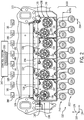
- the first, third, fifth, and seventh metering rollers 190, 192, 194, 196 may be aligned and arranged in a horizontally-extending upper row 198. Stated differently, the axes of rotation of these rollers 190, 192, 194, 196 may be aligned along the lateral axis 124. Additionally, the second, fourth, sixth, and eighth metering roller 191, 193, 195, 197 may be aligned and arranged in a horizontally-extending lower row 199.
- the upper row 198 may be offset from vertical alignment with the lower row 199 (i.e., staggered and spaced apart) at a distance equal to the horizontal distance 168. Also, the upper row 198 may be offset from horizontal alignment with the lower row 199 (i.e., staggered and spaced apart) at a distance equal to the vertical distance 170.
- FIGS. 2 and 3 illustrate the delivery system 132 according to example embodiments.
- the delivery system 132 includes a plurality of tubes 133.
- the plurality of tubes 133 may include a first tube 201, a second tube 202, a third tube 203, a fourth tube 204, a fifth tube 205, a sixth tube 206, a seventh tube 207, an eighth tube 208, a ninth tube 209, a tenth tube 210, an eleventh tube 211, a twelfth tube 212, a thirteenth tube 213, a fourteenth tube 214, a fifteenth tube 215, and a sixteenth tube 216.
- each of these tubes 201-216 may include a segment that is fixed to the frame 110 of the work vehicle 100 below the metering system 130.
- the longitudinal axis of these segments of the tubes 201-216 may be substantially parallel to each other and may be substantially parallel to longitudinal axis 118.
- the tubes 201-216 may be substantially parallel to the metering rollers 190-197.
- the tubes 201-216 may also be fluidly connected (in fluid communication) with the metering system 130.
- a first chute 220 may connect the first tube 201 to the second outlet 152 of the first metering unit 135, and a second chute 222 may connect the second tube 202 to the second outlet 152 as well.
- the delivery system 132 may include a valve 230 that may be disposed within the first chute 220 and/or the second chute 222 and that may move to control flow of the commodity therethrough.
- the valve 230 may be a flap that is rotationally supported at a branch between the first and second chute 220, 222. The valve 230 may rotate to open and shut the chutes 220, 222 to control flow.
- a third chute 224 may connect the third tube 203 to the first outlet 150 of the first metering unit 135, and a fourth chute 226 may connect the fourth tube 204 to the first outlet 150 as well.
- the third chute 224 and the fourth chute 226 may include a respective valve 230 as well.
- the remaining tubes 205-216 may be similarly connected to the second, third, and fourth metering units 136, 137, 138.
- the tubes 201-216 may be organized into groups. Each group of tubes 201-216 may be configured to receive commodity metered out from a single one of the plurality of metering rollers 190-197.
- the first tube 201 and the second tube 202 may be paired together in such a group 240 and may receive commodity metered out from the second metering roller 191.
- the third tube 203 and fourth tube 204 may be paired into a group 241 and may receive commodity metered out from the first metering roller 190.
- the remaining tubes 205-216 may be similarly paired into groups as well.
- the tubes 201-216 may propel the commodity away from the work vehicle 100.
- commodity from the second metering roller 191 may move into the first tube 201.
- the commodity in the first tube 201 may be propelled toward the manifold 129 ( FIG. 1 ), which may split this amount of commodity between the branch lines 131 for delivery to the different row units 101.
- commodity from the second metering roller 191 may also move into the second tube 202, and this amount may move to a different manifold 129 for delivery to a different group of row units 101.
- the other tubes 203-216 may move commodity to different manifolds 129 for delivery to the remaining row units 101.
- valves 230 may be moved to cut off flow to respective tubes 201-216.
- the shut off valves 160 may be moved to cut off flow further upstream as discussed above.
- the control system 140 may turn off the actuators 180, 181 to cut off supply of the commodity as discussed above.
- the plurality of tubes 201-216 of the delivery system 132 may be arranged in a compact manner.
- the first, third, fifth, seventh, ninth, eleventh, thirteenth, and fifteenth tube 201, 203, 205, 207, 209, 211, 213, 215 may be aligned and arranged in a horizontally-extending upper row 250.
- the second, fourth, sixth, eighth, tenth, twelfth, fourteenth, and sixteenth tube 202, 204, 206, 208, 210, 212, 214, 216 may be aligned and arranged in a horizontally-extending lower row 252.
- the upper row 250 may be offset from vertical alignment with the lower row 252 (i.e., staggered and spaced apart) at a distance equal to a horizontal distance 254. Moreover, the upper row 250 may be offset from horizontal alignment with the lower row 252 (i.e., staggered and spaced apart) at a distance equal to a vertical distance 256.
- the metering system 130 and delivery system 132 may be compact and well-organized despite the large number of components and given the limited amount of space. Accordingly, the work vehicle 100 may deliver a controlled amount of commodity to a large number of row units 101 for efficient planting operations.
Landscapes
- Life Sciences & Earth Sciences (AREA)
- Soil Sciences (AREA)
- Environmental Sciences (AREA)
- Sowing (AREA)
- Fertilizing (AREA)
Claims (15)
- Véhicule de travail (100) doté d'un système de dosage de produit comprenant :une cuve à produit (128) ;un système d'actionnement comptant une pluralité d'actionneurs (180, 181) ;un système de distribution (132) comptant une pluralité de tubes (133) ; etun système de dosage (130) comptant une pluralité de rouleaux doseurs (190-197) configurés pour être actionnés individuellement par des actionneurs respectifs de la pluralité d'actionneurs (180, 181) afin de doser un produit sortant de la cuve à produit (128) vers des tubes respectifs de la pluralité de tubes (133), les rouleaux de la pluralité de rouleaux doseurs (190-197) étant disposés sensiblement parallèlement les uns aux autres, les rouleaux de la pluralité de rouleaux doseurs (190-197) étant disposés en quinconce dans un sens vertical (126) et en quinconce dans un sens horizontal (124).
- Véhicule de travail (100) selon la revendication 1, dans lequel les rouleaux de la pluralité de rouleaux doseurs (190-197 sont disposés sur une première rangée (198) et une seconde rangée (199), la première rangée (198) étant espacée à une distance verticale (170) de la seconde rangée (199), la première rangée (198) étant décalée à une distance horizontale (168) par rapport à la seconde rangée (199).
- Véhicule de travail (100) selon la revendication 1 ou 2, dans lequel au moins un tube de la pluralité de tubes (133) est raccordé fonctionnellement à un distributeur aval (129), le distributeur aval étant configuré pour diriger le produit entre une pluralité d'unités en rangées (101) pour sa distribution au sol.
- Véhicule de travail (100) selon la revendication 1, 2 ou 3, dans lequel la pluralité de tubes (133) comporte au moins un groupe de tubes (240, 241) configurés chacun pour recevoir un produit dosé à partir d'un rouleau unique de la pluralité de rouleaux doseurs (190-197).
- Véhicule de travail (100) selon la revendication 1, 2, 3 ou 4, dans lequel les tubes de la pluralité de tubes (133) sont disposés sensiblement parallèlement les uns aux autres, les tubes de la pluralité de tubes (133) étant disposés en quinconce dans le sens vertical (126) et en quinconce dans le sens horizontal (124).
- Véhicule de travail (100) selon la revendication 5, dans lequel les tubes de la pluralité de tubes (133) sont disposés sensiblement parallèlement à la pluralité de rouleaux doseurs (190-197).
- Véhicule de travail (100) selon n'importe quelle revendication précédente, comprenant en outre un châssis (110) qui soutient le système de dosage (130) ; et comprenant en outre un logement (158) qui abrite un groupe de rouleaux de la pluralité de rouleaux doseurs (190-197) ; le logement (158) étant fixé de manière amovible au châssis (110).
- Véhicule de travail (100) selon la revendication 7, dans lequel le logement (158) est l'un d'une pluralité de logements (158) qui abrite différents groupes de rouleaux de la pluralité de rouleaux doseurs (190-197) ;
dans lequel la pluralité de logements (158) est disposée en une rangée qui s'étend dans le sens horizontal (124) ; et
dans lequel le groupe comporte un premier rouleau (190) et un second rouleau (191) qui sont espacés à une distance verticale (170) ; et dans lequel le premier rouleau (190) et le second rouleau (191) sont espacés à une distance horizontale (168). - Véhicule de travail (100) selon la revendication 8, dans lequel au moins un logement de la pluralité de logements (158) comporte un intérieur (142), les premier et deuxième rouleaux (190, 191) étant soutenus en rotation au sein de l'intérieur (142) ;
comprenant en outre un robinet d'arrêt (160) qui est disposé au sein de l'intérieur (142), le robinet d'arrêt (160) ayant une première position et une seconde position ;
le robinet d'arrêt (160), dans la première position, étant configuré pour empêcher le déplacement du produit de la cuve à produit (128) vers les premier et second rouleaux (190, 191) ; et
le robinet d'arrêt(160), dans la seconde position, étant configuré pour permettre le déplacement du produit déplacer de la cuve à produit (128) vers les premier et second rouleaux (190, 191). - Véhicule de travail (100) selon la revendication 9, dans lequel le premier rouleau (190) est configuré pour tourner autour d'un premier axe de rotation (164) afin de doser le produit sortant de la cuve à produit (128) ;
dans lequel le second rouleau (191) est configuré pour tourner autour d'un deuxième axe de rotation (166) afin de doser le produit sortant de la cuve à produit (128) ;
dans lequel le robinet d'arrêt (160) est configuré pour tourner autour d'un troisième axe de rotation (162) quand il est déplacé entre la première position et la seconde position ; et
dans lequel les premier, deuxième et troisième axes de rotation (164, 166, 162) sont sensiblement parallèles. - Véhicule de travail (100) selon n'importe quelle revendication précédente, comprenant en outre un système de commande (140) configuré pour générer des signaux de commande pour la pluralité d'actionneurs (180, 181) afin d'actionner sélectivement des rouleaux individuels de la pluralité de rouleaux doseurs (190-197).
- Véhicule de travail (100) selon la revendication 1, dans lequel le système de dosage (130) comporte en outre un logement (158) et un passage (142) défini à travers le logement (158) configuré pour recevoir un produit à partir de la cuve à produit (128), dans lequel un premier rouleau doseur (190) de la pluralité de rouleaux doseurs (190-197) et un second rouleau doseur (191) de la pluralité de rouleaux doseurs (190-197) sont au moins partiellement disposés à l'intérieur du passage (142) du logement (158), le premier rouleau doseur (190) étant configuré pour être entraîné en rotation par un premier actionneur (180) de la pluralité d'actionneurs (180, 181) afin de doser le produit à travers le passage (142) vers le système de distribution (132), le second rouleau doseur (191) de la pluralité de rouleaux doseurs (190-197) étant configuré pour être entraîné en rotation par un second actionneur (181) de la pluralité d'actionneurs (180, 181) afin de doser le produit à travers le passage (142) vers le système de distribution (132).
- Véhicule de travail (100) selon la revendication 12, dans lequel le premier rouleau doseur (190) de la pluralité de rouleaux doseurs (190-197) et le second rouleau doseur (191) de la pluralité de rouleaux doseurs (190-197) sont décalés dans un sens horizontal (124) et dans un sens vertical (126).
- Véhicule de travail (100) selon la revendication 12 ou 13, dans lequel le premier rouleau doseur (190) de la pluralité de rouleaux doseurs (190-197), le second rouleau doseur (191) de la pluralité de rouleaux doseurs (190-197), et au moins un tube (133) de la pluralité de tubes (133) sont sensiblement parallèles.
- Véhicule de travail (100) selon la revendication 12, 13 ou 14, dans lequel l'au moins un tube (133) de la pluralité de tubes(133) comporte un premier tube (201) et un second tube (202) ;
dans lequel le passage du logement (158) comporte une entrée (146) configurée pour recevoir le produit à partir de la cuve à produit (128) en vue du dosage de celui-ci par le premier rouleau doseur (190) de la pluralité de rouleaux doseurs (190-197) et le second rouleau doseur (191) de la pluralité de rouleaux doseurs (190-197) ;
dans lequel le passage (142) comporte une première sortie (150) configurée pour passer le produit dosé par le premier rouleau doseur (190) de la pluralité de rouleaux doseurs (190-197) au premier tube (201) de la pluralité de tubes (133) ; et
dans lequel le passage (142) comporte une seconde sortie (152) configurée pour passer le produit dosé par le second rouleau doseur (191) de la pluralité de rouleaux doseurs (190-197) au second tube (202) de la pluralité de tubes (133).
Applications Claiming Priority (1)
| Application Number | Priority Date | Filing Date | Title |
|---|---|---|---|
| US16/007,358 US11140811B2 (en) | 2018-06-13 | 2018-06-13 | Commodity metering system for work vehicle with rollers in staggered arrangement |
Publications (2)
| Publication Number | Publication Date |
|---|---|
| EP3581010A1 EP3581010A1 (fr) | 2019-12-18 |
| EP3581010B1 true EP3581010B1 (fr) | 2021-03-17 |
Family
ID=66397060
Family Applications (1)
| Application Number | Title | Priority Date | Filing Date |
|---|---|---|---|
| EP19172404.6A Active EP3581010B1 (fr) | 2018-06-13 | 2019-05-02 | Système de mesure de marchandises pour un véhicule de travail doté de rouleaux agencés en quinconce |
Country Status (4)
| Country | Link |
|---|---|
| US (1) | US11140811B2 (fr) |
| EP (1) | EP3581010B1 (fr) |
| AU (1) | AU2019203330B2 (fr) |
| CA (1) | CA3041222A1 (fr) |
Families Citing this family (4)
| Publication number | Priority date | Publication date | Assignee | Title |
|---|---|---|---|---|
| US11140811B2 (en) * | 2018-06-13 | 2021-10-12 | Deere & Company | Commodity metering system for work vehicle with rollers in staggered arrangement |
| SE543706C2 (sv) * | 2019-04-16 | 2021-06-22 | Vaederstad Holding Ab | Anordning, förfarande, matarhus samt landbruksredskap för luftflödesassisterad matning av granulärt material; stomme samt förfarande för bildande av ett matarhus |
| US11305951B2 (en) * | 2020-03-25 | 2022-04-19 | Deere & Company | Coordinated control of commodity container pressure selection with run selection in a commodity delivery system of a work vehicle |
| US12584780B2 (en) * | 2022-04-04 | 2026-03-24 | Deere & Company | Methods, systems, and apparatuses for bulk material meter calibration |
Family Cites Families (24)
| Publication number | Priority date | Publication date | Assignee | Title |
|---|---|---|---|---|
| US4852809A (en) * | 1987-10-06 | 1989-08-01 | Willmar Manufacturing, A Division Of Waycrosse, Inc. | Pneumatic spreader |
| US5845818A (en) | 1997-08-18 | 1998-12-08 | Deere & Company | Removable meter cartridge for metering system |
| US7380733B2 (en) * | 2005-07-21 | 2008-06-03 | Barron & Brothers International | Plural bin metering system |
| US8001915B2 (en) * | 2008-06-18 | 2011-08-23 | Cnh Canada, Ltd. | Metering system for agricultural implement and having sectional control |
| US8132521B2 (en) | 2009-06-09 | 2012-03-13 | Deere & Company | Volumetric metering system with sectional shut-off |
| US8915200B2 (en) * | 2011-02-18 | 2014-12-23 | Morris Industries Ltd. | Seeder with metering system having selectively powered metering sections |
| US8671857B2 (en) | 2011-03-10 | 2014-03-18 | Cnh Canada, Ltd. | Variable geometry meter roller |
| US9144190B2 (en) * | 2012-01-23 | 2015-09-29 | Cnh Industrial Canada, Ltd. | Particulate material delivery system for variable rate sectional control |
| US20140076218A1 (en) | 2012-09-14 | 2014-03-20 | James Z. Liu | Product distribution device with flow rate and section control monitoring |
| WO2014040190A1 (fr) | 2012-09-14 | 2014-03-20 | One Pass Implements Inc. | Système de mesure avec sections de mesure actionnées individuellement |
| US20140261117A1 (en) | 2013-03-12 | 2014-09-18 | Salford Farm Machinery Ltd. | Metering apparatus and method for sectional control |
| US9363942B2 (en) * | 2013-03-15 | 2016-06-14 | Cnh Industrial Canada, Ltd. | Run selection mechanism |
| US9546051B2 (en) * | 2013-12-17 | 2017-01-17 | Cnh Industrial Canada, Ltd. | System for increasing throughput of an agricultural product metering system |
| US9497899B2 (en) * | 2013-12-31 | 2016-11-22 | Morris Industries Ltd. | Sensor for air cart metering system |
| CA2904756C (fr) * | 2014-11-04 | 2020-01-07 | Cnh Industrial Canada, Ltd. | Rouleaux doseurs a controle independant et systeme et methode de composantes de transport a air |
| CA2904759C (fr) * | 2014-11-04 | 2021-01-12 | Cnh Industrial Canada, Ltd. | Systeme et methode de dosage de produits agricoles |
| CA2904778C (fr) * | 2014-11-04 | 2020-03-10 | Cnh Industrial Canada, Ltd. | Systeme et methode d'etalonnage independant de rouleaux doseurs |
| US9854732B2 (en) * | 2015-08-31 | 2018-01-02 | Cnh Industrial Canada, Ltd. | Metering system for an agricultural vehicle |
| US9801330B2 (en) * | 2015-11-04 | 2017-10-31 | Cnh Industrial Canada, Ltd. | Meter roller cartridge frame for an agricultural metering system |
| US10375876B2 (en) | 2016-03-23 | 2019-08-13 | J & L Custom Fence, Inc. | Variable rate air seeding system for soybeans |
| CA2944655C (fr) * | 2016-10-07 | 2023-08-08 | Seedmaster Manufacturing Ltd. | Appareil de mesure modulaire destine a un semoir pneumatique |
| US10555455B2 (en) * | 2017-08-07 | 2020-02-11 | Deere & Company | Work vehicle with commodity metering system and airflow system |
| US11140811B2 (en) * | 2018-06-13 | 2021-10-12 | Deere & Company | Commodity metering system for work vehicle with rollers in staggered arrangement |
| US10694660B2 (en) * | 2018-06-20 | 2020-06-30 | Deere & Company | Commodity delivery system for work vehicle with rotary manifold regulator |
-
2018
- 2018-06-13 US US16/007,358 patent/US11140811B2/en active Active
-
2019
- 2019-04-25 CA CA3041222A patent/CA3041222A1/fr active Pending
- 2019-05-02 EP EP19172404.6A patent/EP3581010B1/fr active Active
- 2019-05-13 AU AU2019203330A patent/AU2019203330B2/en active Active
Non-Patent Citations (1)
| Title |
|---|
| None * |
Also Published As
| Publication number | Publication date |
|---|---|
| AU2019203330B2 (en) | 2025-04-03 |
| CA3041222A1 (fr) | 2019-12-13 |
| EP3581010A1 (fr) | 2019-12-18 |
| US20190380263A1 (en) | 2019-12-19 |
| US11140811B2 (en) | 2021-10-12 |
| AU2019203330A1 (en) | 2020-01-16 |
| BR102019009069A2 (pt) | 2019-12-17 |
Similar Documents
| Publication | Publication Date | Title |
|---|---|---|
| US9801330B2 (en) | Meter roller cartridge frame for an agricultural metering system | |
| AU2019203330B2 (en) | Commodity metering system for work vehicle with rollers in staggered arrangement | |
| AU2019203537B2 (en) | Commodity delivery system for work vehicle with rotary manifold regulator | |
| CN105120648B (zh) | 具有颗粒分配系统的农业机具 | |
| US9648802B2 (en) | Multiple seed-type planter with on-row selector assembly | |
| US10448562B2 (en) | Agricultural air cart apparatus | |
| EP3884753B1 (fr) | Engin de travail | |
| AU2010235883A1 (en) | Volumetric metering system with sectional shut-off | |
| EP3513642B1 (fr) | Système d'échappement pour système d'alimentation de pression d'air d'un véhicule de travail | |
| AU2019236587B2 (en) | Commodity metering system for work vehicle with transverse drive for metering element | |
| US11885424B2 (en) | Airflow equalizing system for distributing particulate material | |
| BR102019009069B1 (pt) | Veículo de trabalho | |
| US11662240B2 (en) | Variable rate air metering system |
Legal Events
| Date | Code | Title | Description |
|---|---|---|---|
| PUAI | Public reference made under article 153(3) epc to a published international application that has entered the european phase |
Free format text: ORIGINAL CODE: 0009012 |
|
| STAA | Information on the status of an ep patent application or granted ep patent |
Free format text: STATUS: THE APPLICATION HAS BEEN PUBLISHED |
|
| AK | Designated contracting states |
Kind code of ref document: A1 Designated state(s): AL AT BE BG CH CY CZ DE DK EE ES FI FR GB GR HR HU IE IS IT LI LT LU LV MC MK MT NL NO PL PT RO RS SE SI SK SM TR |
|
| AX | Request for extension of the european patent |
Extension state: BA ME |
|
| STAA | Information on the status of an ep patent application or granted ep patent |
Free format text: STATUS: REQUEST FOR EXAMINATION WAS MADE |
|
| 17P | Request for examination filed |
Effective date: 20200618 |
|
| RBV | Designated contracting states (corrected) |
Designated state(s): AL AT BE BG CH CY CZ DE DK EE ES FI FR GB GR HR HU IE IS IT LI LT LU LV MC MK MT NL NO PL PT RO RS SE SI SK SM TR |
|
| GRAP | Despatch of communication of intention to grant a patent |
Free format text: ORIGINAL CODE: EPIDOSNIGR1 |
|
| STAA | Information on the status of an ep patent application or granted ep patent |
Free format text: STATUS: GRANT OF PATENT IS INTENDED |
|
| INTG | Intention to grant announced |
Effective date: 20201127 |
|
| GRAS | Grant fee paid |
Free format text: ORIGINAL CODE: EPIDOSNIGR3 |
|
| GRAA | (expected) grant |
Free format text: ORIGINAL CODE: 0009210 |
|
| STAA | Information on the status of an ep patent application or granted ep patent |
Free format text: STATUS: THE PATENT HAS BEEN GRANTED |
|
| AK | Designated contracting states |
Kind code of ref document: B1 Designated state(s): AL AT BE BG CH CY CZ DE DK EE ES FI FR GB GR HR HU IE IS IT LI LT LU LV MC MK MT NL NO PL PT RO RS SE SI SK SM TR |
|
| REG | Reference to a national code |
Ref country code: GB Ref legal event code: FG4D |
|
| REG | Reference to a national code |
Ref country code: CH Ref legal event code: EP |
|
| REG | Reference to a national code |
Ref country code: DE Ref legal event code: R096 Ref document number: 602019003181 Country of ref document: DE |
|
| REG | Reference to a national code |
Ref country code: IE Ref legal event code: FG4D |
|
| REG | Reference to a national code |
Ref country code: AT Ref legal event code: REF Ref document number: 1371311 Country of ref document: AT Kind code of ref document: T Effective date: 20210415 |
|
| REG | Reference to a national code |
Ref country code: LT Ref legal event code: MG9D |
|
| PG25 | Lapsed in a contracting state [announced via postgrant information from national office to epo] |
Ref country code: FI Free format text: LAPSE BECAUSE OF FAILURE TO SUBMIT A TRANSLATION OF THE DESCRIPTION OR TO PAY THE FEE WITHIN THE PRESCRIBED TIME-LIMIT Effective date: 20210317 Ref country code: HR Free format text: LAPSE BECAUSE OF FAILURE TO SUBMIT A TRANSLATION OF THE DESCRIPTION OR TO PAY THE FEE WITHIN THE PRESCRIBED TIME-LIMIT Effective date: 20210317 Ref country code: GR Free format text: LAPSE BECAUSE OF FAILURE TO SUBMIT A TRANSLATION OF THE DESCRIPTION OR TO PAY THE FEE WITHIN THE PRESCRIBED TIME-LIMIT Effective date: 20210618 Ref country code: BG Free format text: LAPSE BECAUSE OF FAILURE TO SUBMIT A TRANSLATION OF THE DESCRIPTION OR TO PAY THE FEE WITHIN THE PRESCRIBED TIME-LIMIT Effective date: 20210617 Ref country code: NO Free format text: LAPSE BECAUSE OF FAILURE TO SUBMIT A TRANSLATION OF THE DESCRIPTION OR TO PAY THE FEE WITHIN THE PRESCRIBED TIME-LIMIT Effective date: 20210617 |
|
| REG | Reference to a national code |
Ref country code: AT Ref legal event code: MK05 Ref document number: 1371311 Country of ref document: AT Kind code of ref document: T Effective date: 20210317 |
|
| REG | Reference to a national code |
Ref country code: NL Ref legal event code: MP Effective date: 20210317 |
|
| PG25 | Lapsed in a contracting state [announced via postgrant information from national office to epo] |
Ref country code: SE Free format text: LAPSE BECAUSE OF FAILURE TO SUBMIT A TRANSLATION OF THE DESCRIPTION OR TO PAY THE FEE WITHIN THE PRESCRIBED TIME-LIMIT Effective date: 20210317 Ref country code: RS Free format text: LAPSE BECAUSE OF FAILURE TO SUBMIT A TRANSLATION OF THE DESCRIPTION OR TO PAY THE FEE WITHIN THE PRESCRIBED TIME-LIMIT Effective date: 20210317 Ref country code: LV Free format text: LAPSE BECAUSE OF FAILURE TO SUBMIT A TRANSLATION OF THE DESCRIPTION OR TO PAY THE FEE WITHIN THE PRESCRIBED TIME-LIMIT Effective date: 20210317 |
|
| PG25 | Lapsed in a contracting state [announced via postgrant information from national office to epo] |
Ref country code: NL Free format text: LAPSE BECAUSE OF FAILURE TO SUBMIT A TRANSLATION OF THE DESCRIPTION OR TO PAY THE FEE WITHIN THE PRESCRIBED TIME-LIMIT Effective date: 20210317 |
|
| PG25 | Lapsed in a contracting state [announced via postgrant information from national office to epo] |
Ref country code: SM Free format text: LAPSE BECAUSE OF FAILURE TO SUBMIT A TRANSLATION OF THE DESCRIPTION OR TO PAY THE FEE WITHIN THE PRESCRIBED TIME-LIMIT Effective date: 20210317 Ref country code: AT Free format text: LAPSE BECAUSE OF FAILURE TO SUBMIT A TRANSLATION OF THE DESCRIPTION OR TO PAY THE FEE WITHIN THE PRESCRIBED TIME-LIMIT Effective date: 20210317 Ref country code: CZ Free format text: LAPSE BECAUSE OF FAILURE TO SUBMIT A TRANSLATION OF THE DESCRIPTION OR TO PAY THE FEE WITHIN THE PRESCRIBED TIME-LIMIT Effective date: 20210317 Ref country code: EE Free format text: LAPSE BECAUSE OF FAILURE TO SUBMIT A TRANSLATION OF THE DESCRIPTION OR TO PAY THE FEE WITHIN THE PRESCRIBED TIME-LIMIT Effective date: 20210317 Ref country code: LT Free format text: LAPSE BECAUSE OF FAILURE TO SUBMIT A TRANSLATION OF THE DESCRIPTION OR TO PAY THE FEE WITHIN THE PRESCRIBED TIME-LIMIT Effective date: 20210317 |
|
| PG25 | Lapsed in a contracting state [announced via postgrant information from national office to epo] |
Ref country code: IS Free format text: LAPSE BECAUSE OF FAILURE TO SUBMIT A TRANSLATION OF THE DESCRIPTION OR TO PAY THE FEE WITHIN THE PRESCRIBED TIME-LIMIT Effective date: 20210717 Ref country code: PL Free format text: LAPSE BECAUSE OF FAILURE TO SUBMIT A TRANSLATION OF THE DESCRIPTION OR TO PAY THE FEE WITHIN THE PRESCRIBED TIME-LIMIT Effective date: 20210317 Ref country code: RO Free format text: LAPSE BECAUSE OF FAILURE TO SUBMIT A TRANSLATION OF THE DESCRIPTION OR TO PAY THE FEE WITHIN THE PRESCRIBED TIME-LIMIT Effective date: 20210317 Ref country code: PT Free format text: LAPSE BECAUSE OF FAILURE TO SUBMIT A TRANSLATION OF THE DESCRIPTION OR TO PAY THE FEE WITHIN THE PRESCRIBED TIME-LIMIT Effective date: 20210719 Ref country code: SK Free format text: LAPSE BECAUSE OF FAILURE TO SUBMIT A TRANSLATION OF THE DESCRIPTION OR TO PAY THE FEE WITHIN THE PRESCRIBED TIME-LIMIT Effective date: 20210317 |
|
| REG | Reference to a national code |
Ref country code: DE Ref legal event code: R097 Ref document number: 602019003181 Country of ref document: DE |
|
| PLBE | No opposition filed within time limit |
Free format text: ORIGINAL CODE: 0009261 |
|
| STAA | Information on the status of an ep patent application or granted ep patent |
Free format text: STATUS: NO OPPOSITION FILED WITHIN TIME LIMIT |
|
| PG25 | Lapsed in a contracting state [announced via postgrant information from national office to epo] |
Ref country code: MC Free format text: LAPSE BECAUSE OF FAILURE TO SUBMIT A TRANSLATION OF THE DESCRIPTION OR TO PAY THE FEE WITHIN THE PRESCRIBED TIME-LIMIT Effective date: 20210317 Ref country code: AL Free format text: LAPSE BECAUSE OF FAILURE TO SUBMIT A TRANSLATION OF THE DESCRIPTION OR TO PAY THE FEE WITHIN THE PRESCRIBED TIME-LIMIT Effective date: 20210317 Ref country code: DK Free format text: LAPSE BECAUSE OF FAILURE TO SUBMIT A TRANSLATION OF THE DESCRIPTION OR TO PAY THE FEE WITHIN THE PRESCRIBED TIME-LIMIT Effective date: 20210317 Ref country code: LU Free format text: LAPSE BECAUSE OF NON-PAYMENT OF DUE FEES Effective date: 20210502 Ref country code: ES Free format text: LAPSE BECAUSE OF FAILURE TO SUBMIT A TRANSLATION OF THE DESCRIPTION OR TO PAY THE FEE WITHIN THE PRESCRIBED TIME-LIMIT Effective date: 20210317 |
|
| REG | Reference to a national code |
Ref country code: BE Ref legal event code: MM Effective date: 20210531 |
|
| 26N | No opposition filed |
Effective date: 20211220 |
|
| PG25 | Lapsed in a contracting state [announced via postgrant information from national office to epo] |
Ref country code: SI Free format text: LAPSE BECAUSE OF FAILURE TO SUBMIT A TRANSLATION OF THE DESCRIPTION OR TO PAY THE FEE WITHIN THE PRESCRIBED TIME-LIMIT Effective date: 20210317 |
|
| PG25 | Lapsed in a contracting state [announced via postgrant information from national office to epo] |
Ref country code: IT Free format text: LAPSE BECAUSE OF FAILURE TO SUBMIT A TRANSLATION OF THE DESCRIPTION OR TO PAY THE FEE WITHIN THE PRESCRIBED TIME-LIMIT Effective date: 20210317 Ref country code: IE Free format text: LAPSE BECAUSE OF NON-PAYMENT OF DUE FEES Effective date: 20210502 |
|
| PG25 | Lapsed in a contracting state [announced via postgrant information from national office to epo] |
Ref country code: IS Free format text: LAPSE BECAUSE OF FAILURE TO SUBMIT A TRANSLATION OF THE DESCRIPTION OR TO PAY THE FEE WITHIN THE PRESCRIBED TIME-LIMIT Effective date: 20210717 |
|
| PG25 | Lapsed in a contracting state [announced via postgrant information from national office to epo] |
Ref country code: BE Free format text: LAPSE BECAUSE OF NON-PAYMENT OF DUE FEES Effective date: 20210531 |
|
| REG | Reference to a national code |
Ref country code: CH Ref legal event code: PL |
|
| PG25 | Lapsed in a contracting state [announced via postgrant information from national office to epo] |
Ref country code: LI Free format text: LAPSE BECAUSE OF NON-PAYMENT OF DUE FEES Effective date: 20220531 Ref country code: CH Free format text: LAPSE BECAUSE OF NON-PAYMENT OF DUE FEES Effective date: 20220531 |
|
| PG25 | Lapsed in a contracting state [announced via postgrant information from national office to epo] |
Ref country code: CY Free format text: LAPSE BECAUSE OF FAILURE TO SUBMIT A TRANSLATION OF THE DESCRIPTION OR TO PAY THE FEE WITHIN THE PRESCRIBED TIME-LIMIT Effective date: 20210317 |
|
| PG25 | Lapsed in a contracting state [announced via postgrant information from national office to epo] |
Ref country code: HU Free format text: LAPSE BECAUSE OF FAILURE TO SUBMIT A TRANSLATION OF THE DESCRIPTION OR TO PAY THE FEE WITHIN THE PRESCRIBED TIME-LIMIT; INVALID AB INITIO Effective date: 20190502 |
|
| GBPC | Gb: european patent ceased through non-payment of renewal fee |
Effective date: 20230502 |
|
| PG25 | Lapsed in a contracting state [announced via postgrant information from national office to epo] |
Ref country code: MK Free format text: LAPSE BECAUSE OF FAILURE TO SUBMIT A TRANSLATION OF THE DESCRIPTION OR TO PAY THE FEE WITHIN THE PRESCRIBED TIME-LIMIT Effective date: 20210317 Ref country code: GB Free format text: LAPSE BECAUSE OF NON-PAYMENT OF DUE FEES Effective date: 20230502 |
|
| PG25 | Lapsed in a contracting state [announced via postgrant information from national office to epo] |
Ref country code: TR Free format text: LAPSE BECAUSE OF FAILURE TO SUBMIT A TRANSLATION OF THE DESCRIPTION OR TO PAY THE FEE WITHIN THE PRESCRIBED TIME-LIMIT Effective date: 20210317 |
|
| PG25 | Lapsed in a contracting state [announced via postgrant information from national office to epo] |
Ref country code: MT Free format text: LAPSE BECAUSE OF FAILURE TO SUBMIT A TRANSLATION OF THE DESCRIPTION OR TO PAY THE FEE WITHIN THE PRESCRIBED TIME-LIMIT Effective date: 20210317 |
|
| PGFP | Annual fee paid to national office [announced via postgrant information from national office to epo] |
Ref country code: DE Payment date: 20250423 Year of fee payment: 7 |
|
| PGFP | Annual fee paid to national office [announced via postgrant information from national office to epo] |
Ref country code: FR Payment date: 20250526 Year of fee payment: 7 |