EP3581027B1 - Transportvorrichtung für eier, insbesondere eierelevator - Google Patents
Transportvorrichtung für eier, insbesondere eierelevator Download PDFInfo
- Publication number
- EP3581027B1 EP3581027B1 EP19180413.7A EP19180413A EP3581027B1 EP 3581027 B1 EP3581027 B1 EP 3581027B1 EP 19180413 A EP19180413 A EP 19180413A EP 3581027 B1 EP3581027 B1 EP 3581027B1
- Authority
- EP
- European Patent Office
- Prior art keywords
- eggs
- slots
- transport device
- present
- egg
- Prior art date
- Legal status (The legal status is an assumption and is not a legal conclusion. Google has not performed a legal analysis and makes no representation as to the accuracy of the status listed.)
- Active
Links
Images



Classifications
-
- A—HUMAN NECESSITIES
- A01—AGRICULTURE; FORESTRY; ANIMAL HUSBANDRY; HUNTING; TRAPPING; FISHING
- A01K—ANIMAL HUSBANDRY; AVICULTURE; APICULTURE; PISCICULTURE; FISHING; REARING OR BREEDING ANIMALS, NOT OTHERWISE PROVIDED FOR; NEW BREEDS OF ANIMALS
- A01K31/00—Housing birds
- A01K31/14—Nest-boxes, e.g. for singing birds or the like
- A01K31/16—Laying nests for poultry; Egg collecting
- A01K31/165—Egg collecting or counting
-
- B—PERFORMING OPERATIONS; TRANSPORTING
- B65—CONVEYING; PACKING; STORING; HANDLING THIN OR FILAMENTARY MATERIAL
- B65G—TRANSPORT OR STORAGE DEVICES, e.g. CONVEYORS FOR LOADING OR TIPPING, SHOP CONVEYOR SYSTEMS OR PNEUMATIC TUBE CONVEYORS
- B65G17/00—Conveyors having an endless traction element, e.g. a chain, transmitting movement to a continuous or substantially-continuous load-carrying surface or to a series of individual load-carriers; Endless-chain conveyors in which the chains form the load-carrying surface
- B65G17/12—Conveyors having an endless traction element, e.g. a chain, transmitting movement to a continuous or substantially-continuous load-carrying surface or to a series of individual load-carriers; Endless-chain conveyors in which the chains form the load-carrying surface comprising a series of individual load-carriers fixed, or normally fixed, relative to traction element
-
- B—PERFORMING OPERATIONS; TRANSPORTING
- B65—CONVEYING; PACKING; STORING; HANDLING THIN OR FILAMENTARY MATERIAL
- B65G—TRANSPORT OR STORAGE DEVICES, e.g. CONVEYORS FOR LOADING OR TIPPING, SHOP CONVEYOR SYSTEMS OR PNEUMATIC TUBE CONVEYORS
- B65G17/00—Conveyors having an endless traction element, e.g. a chain, transmitting movement to a continuous or substantially-continuous load-carrying surface or to a series of individual load-carriers; Endless-chain conveyors in which the chains form the load-carrying surface
- B65G17/30—Details; Auxiliary devices
- B65G17/32—Individual load-carriers
- B65G17/36—Individual load-carriers having concave surfaces, e.g. buckets
-
- B—PERFORMING OPERATIONS; TRANSPORTING
- B65—CONVEYING; PACKING; STORING; HANDLING THIN OR FILAMENTARY MATERIAL
- B65G—TRANSPORT OR STORAGE DEVICES, e.g. CONVEYORS FOR LOADING OR TIPPING, SHOP CONVEYOR SYSTEMS OR PNEUMATIC TUBE CONVEYORS
- B65G17/00—Conveyors having an endless traction element, e.g. a chain, transmitting movement to a continuous or substantially-continuous load-carrying surface or to a series of individual load-carriers; Endless-chain conveyors in which the chains form the load-carrying surface
- B65G17/30—Details; Auxiliary devices
- B65G17/38—Chains or like traction elements; Connections between traction elements and load-carriers
-
- B—PERFORMING OPERATIONS; TRANSPORTING
- B65—CONVEYING; PACKING; STORING; HANDLING THIN OR FILAMENTARY MATERIAL
- B65G—TRANSPORT OR STORAGE DEVICES, e.g. CONVEYORS FOR LOADING OR TIPPING, SHOP CONVEYOR SYSTEMS OR PNEUMATIC TUBE CONVEYORS
- B65G47/00—Article or material-handling devices associated with conveyors; Methods employing such devices
- B65G47/52—Devices for transferring articles or materials between conveyors i.e. discharging or feeding devices
- B65G47/66—Fixed platforms or combs, e.g. bridges between conveyors
-
- B—PERFORMING OPERATIONS; TRANSPORTING
- B65—CONVEYING; PACKING; STORING; HANDLING THIN OR FILAMENTARY MATERIAL
- B65B—MACHINES, APPARATUS OR DEVICES FOR, OR METHODS OF, PACKAGING ARTICLES OR MATERIALS; UNPACKING
- B65B23/00—Packaging fragile or shock-sensitive articles other than bottles; Unpacking eggs
- B65B23/02—Packaging or unpacking eggs
- B65B23/06—Arranging, feeding, or orientating the eggs to be packed; Removing eggs from trays or cartons
-
- B—PERFORMING OPERATIONS; TRANSPORTING
- B65—CONVEYING; PACKING; STORING; HANDLING THIN OR FILAMENTARY MATERIAL
- B65G—TRANSPORT OR STORAGE DEVICES, e.g. CONVEYORS FOR LOADING OR TIPPING, SHOP CONVEYOR SYSTEMS OR PNEUMATIC TUBE CONVEYORS
- B65G2201/00—Indexing codes relating to handling devices, e.g. conveyors, characterised by the type of product or load being conveyed or handled
- B65G2201/02—Articles
- B65G2201/0202—Agricultural and processed food products
- B65G2201/0208—Eggs
Definitions
- the invention relates to an egg transport device, in particular an egg lift, comprising:
- a transport device is known from WO2006/074077A .
- This known transport device is not specifically designed for conveying eggs. If this known transport device were used for conveying eggs, problems could arise during the supply of eggs and the subsequent conveyance of the eggs because the eggs end up on top of each other at the supply point and are thereby damaged and / or supplied in longitudinal direction transversely to the carriers, so that they can get jammed between consecutive carriers and be crushed.
- the egg transport device is characterized in that the top side of the fingers has a greater friction coefficient than the friction coefficient of the front side of the carrier teeth so that during operation the eggs roll over the top side of the fingers and slide along the front side of the carrier teeth. Since the eggs roll over the fingers at the feeding means, eggs present on top of each other will roll off each other and the eggs will always be carried along with their longitudinal direction parallel to the longitudinal direction of the carriers. As a result, there is no or hardly any chance of the eggs being damaged.
- the eggs roll from a conveyor feeding belt onto the feeding plate and are taken along by the carriers in the same direction as the rolling direction. Only after the eggs have been taken along by the carriers will the transport direction gradually change to the vertical direction. The eggs are thus carried along smoothly and the change of direction also takes place smoothly. As a result, the chance of damage to the eggs is smaller than with the known egg transport device and no blockages due to feeding disturbances can arise.
- the egg transport device according to the invention can cope better with disruptions in the supply because the objects (dung clods, dead chickens, etc.) not belonging to the egg flow are taken along by the carriers and drop from the egg transport device at the gradual transition from the horizontal direction to the vertical direction.
- the processing capacity of eggs may be greater than the feeding capacity of the conveyor belt, so that congestion of eggs can be avoided.
- the transport means run faster than the conveyor belt, the supply flow of eggs is stretched so that no blockage can occur. If the eggs were lying on top of each other in the supply flow, the bottom eggs would be carried along smoothly and the top eggs would gradually roll off the bottom eggs. This is in contrast to the known transport device in which the top eggs will abruptly fall off the bottom eggs.
- the friction coefficient between the eggs and the fingers is greater than that between the eggs and the carriers, causing the eggs to roll over the fingers and not slide.
- the eggs will spread out better across the width of the carriers and they will lie horizontally with their longitudinal axis parallel to the longitudinal axis of the carriers, so that the carriers can be placed a shorter distance apart, so that the capacity increases at the same transfer rate.
- An embodiment of the egg transport device according to the invention is characterized in that the fingers are flexible in a direction perpendicular to the top side of the feeding plate. This even further reduces the risk of damage to the eggs during operation.
- the fingers are preferably so flexible that during operation they bend under the weight of the eggs and are supported by the parts of the carriers present between the carrier teeth, so that they do not bend any further.
- a still further embodiment of the egg transport device is characterized in that the transport element comprises a chain which is movable along a guide of the transport means and includes a plurality of mutually connected links connected by link pins which are present at right angles to the longitudinal direction of the transport element, wherein in one of two mutually connected links the link pin is present with play in a slotted hole and an elastic spacer is present between the link pin and the side of the boundary wall of the hole located close to the other one of the two links.
- the elastic spacers By stretching the chain, whereby successive / adjacent links are pulled away from each other, the elastic spacers will be resilient and thereby keep the chain in tension. This makes it possible to dispense with a chain tensioner when such a chain is used, because the chain itself maintains tension when it is mounted in a slightly stretched state.
- the use of such a chain also allows the egg transport device to work in two directions without the need to adjust / move a tensioning device for this purpose.
- a chain in which the link pins via which the links are connected to each other are present with play in holes and elastic spacers are located between the link pins and the boundary walls of the holes, which elastic spacers put an end to the play and by stretching the links show a resilient behaviour and thereby are able to keep the chain in tension, can also be used in devices or systems other than the egg lift described here and that the possibility of protecting such a chain separately is maintained.
- the link pin preferably has a reduced diameter in the middle or has a recess and in that the spacer is partly present in the reduced-diameter area or recess. As a result, the spacer also ensures axial confinement of the link pin.
- links are preferably provided with stops which limit the mutual rotation of the links around the link pins, so that the chance of the chain getting jammed is smaller and the eggs are not crushed.
- a further embodiment of the egg transport device according to the invention is characterized in that the guide comprises two metal rods running parallel to each other and each link is provided with plastic guide elements which are movable along the rods.
- the guides By making the guides of a high-quality material, the links can be made of a relatively inexpensive plastic.
- Each guide element preferably comprises two spaced plastic lips which are present on either one of the two sides of one of the metal rods during guiding and if they come loose from the metal rods at or close to the feeding means, are able by themselves to slide around the metal rod.
- the lips are designed such that they can be caught by the rods and slide onto the rods.
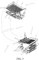
- Fig. 1 shows an egg transport device designed as an egg lift, partly shown diagrammatically.
- the egg lift 1 comprises feeding means 3 for feeding eggs, as well as discharge means 5 for discharging eggs, and transport means 7 located between the feeding means and the discharge means for transferring eggs in vertical direction.
- the feeding means have a feeding plate 9 with a top side 11 onto which the eggs roll coming from a conveyor belt during operation.
- the discharge means are provided with a discharge plate 13 having a top side 15 from which the eggs are discharged.
- the transport means 7 have a flexible endless transport element 8 which is provided with comb-shaped carriers 17 which are arranged one behind the other and which are provided with adjacent carrier teeth 19.
- the transport means further have a frame formed by mutually attached frame parts 21, 23 to which two parallel guide rods 25 are attached which form the guide along which the transport element can be moved.
- Figs. 3 and 4 show the feeding means 3 and the discharge means 5 in side view and in sectional view, respectively.
- the feeding plate 9 and discharge plate 13 are substantially identical. Only the orientation and direction of movement of the transport element 8 relative to the feeding and discharge plates is different.
- Fig. 2 shows a perspective view of the discharge means 5 by way of illustration.
- the feeding plate 9 and the discharge plate 13 are provided with a plurality of parallel slots 27 of which an open end 27A s present at an edge 9A, 13A respectively, of the feeding plate or discharge plate respectively and a closed end 27B is present spaced from the opposite edge 9B, 13B respectively, of the feeding plate or discharge plate. From this opposite edge the eggs 2 are fed or discharged respectively, and they roll into or out of the egg lift.
- the parts located between the slots 27 of the feeding plate form resilient fingers 29.
- the top side 30 of the fingers 29 has a higher friction coefficient than that of the front side 20 of the carrier teeth 19, so that during operation the eggs 2 roll over the top side 30 of the fingers and slide along the front side 20 of the carrier teeth.
- the fingers 29 are flexible in a direction perpendicular to the top side 11 of the feeding plate 9. The fingers 29 are so flexible that during operation they bend under the weight of the eggs 2 and are supported by the parts of the carriers located between the carrier teeth 19 so that they do not bend through any further. Also at the discharge means the surface of the top side of the fingers is rougher than that of the front side of the carrier teeth.
- Fig. 4 shows a sectional view of the discharge means.
- the discharge plate 13 is provided with a plurality of parallel further slots 31 (see also Fig. 1 ) of which an open end 31A is present at an edge 13A of the discharge plate and a closed end 31B is present at a distance from the opposite edge 13B of the discharge plate.
- the carrier teeth 19 of the comb-shaped carriers 17 move through the slots 27 and further slots 31 during the operation of the egg lift.
- the free ends 19A of the carrier teeth 19 move from below through the slots close to the closed end 27B of the slots and when they move towards the open end 27A of the slots, the carrier teeth 19 rise above the slots with an increasing length while taking the eggs along. This is clearly visible in Fig. 3 .
- the carrier teeth 19 of the carriers 17 enter the further slots via the open end 31A, while the free ends 19A of the carrier teeth project to their full extent above the further slots 31.
- the carrier teeth 19 project with a diminishing length above the further slots and thereby release the eggs, until the free ends finally disappear completely into the further slots.
- the eggs 2 are smoothly pushed onto the discharge plate 13.
- the transport element is formed by a chain 33 which can be moved along the guide rods.
- the chain is comprised of a plurality of mutually connected links 35. These links are connected to each other by link pins 37 which are present at right angles to the longitudinal direction of the chain.
- the chain is driven by a sprocket 39.
- the carriers 17 are releasably arranged on the links and may also be arranged on the links in a position rotated through 180 degrees if the direction of transport of the chain were reversed.
- a carrier 17 mounted on a link 35 is shown in enlarged fashion.
- the carrier teeth 19 are bent forwards in the direction of transport.
- the link is provided with a slotted hole through which a link pin 37 projects with play.
- the link is furthermore provided with stops which limit the mutual rotation of the links around the link pins. These stops are formed by elongated ends 19B of the carrier teeth 19 located in the middle of the carrier 17.
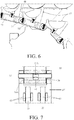
- Fig. 6 shows a sectional view of the detail of the feeding means shown in Fig. 3 in which the mutual coupling of the links is clearly visible.
- Fig. 7 shows a top view of a detail of the coupling of two links.
- the link pin 37 is located with play in a hole 39 in one of the links 35. Between the link pin 37 and the side 39A of the boundary wall of the hole near the other one of the two links 35' an elastic spacer 41 is positioned which makes it possible to install the chain in the egg lift under pretension so that a chain tensioner may be omitted.
- the link pin 37 has a reduced diameter 37A in the middle and the spacer 41 is partly present in the reduced-diameter region to enclose the link pin 37 in axial direction.
- each link has two pairs of plastic guide elements 43 which are slidable along the two parallel guide rods 25 (for example made of stainless steel and / or chrome). These guide elements are formed by plastic lips which are present on both sides of one of the metal rods during the guiding action. If the links in the returning part of the chain became detached from the guide, the lips at the feeding means would slide over the metal rods again.
- Fig. 8 shows an alternative embodiment of the discharge means.
- the discharge plate 13' is not provided with slots and is located at a lower level.
- the eggs 2 taken along by the carriers 17 roll from the carrier teeth 19 onto the discharge plate 13' as a result of gravity.
- the carrier teeth 19 of the carriers 17 move just along the discharge plate. Since the carrier teeth need not move through slots, there is less chance of the transport means getting disrupted.
Landscapes
- Engineering & Computer Science (AREA)
- Mechanical Engineering (AREA)
- Life Sciences & Earth Sciences (AREA)
- Birds (AREA)
- Environmental Sciences (AREA)
- Zoology (AREA)
- Animal Husbandry (AREA)
- Biodiversity & Conservation Biology (AREA)
- Intermediate Stations On Conveyors (AREA)
- Wrapping Of Specific Fragile Articles (AREA)
- Housing For Livestock And Birds (AREA)
- Chain Conveyers (AREA)
Claims (9)
- Eiertransportvorrichtung, insbesondere ein Eierlift (1), umfassend:- Eingabemittel (3) zum Einführen von Eiern (2) in die Eitransportvorrichtung, wobei die Eingabemittel (3) eine Zufuhrplatte (9) mit einer Oberseite (11) umfassen, auf der Eier zugeführt werden, wobei die Zufuhrplatte mit einer Anzahl von parallelen, gegenseitig beabstandeten Schlitze (27) versehen ist, von denen ein offenes Ende (27A) an einer Kante (9A) der Zuführplatte vorgesehen ist und ein geschlossenes Ende (27B) beabstandet von der gegenüberliegenden Kante (9B) der Zuführplatte vorgesehen ist, wobei die Eier von diese gegenüberliegende Kante (9B) zugeführt werden, und wobei die Teile der Zufuhrplatte (9), die zwischen den Schlitzen (27) vorhanden sind, Finger (29) bilden,- Ausgabemittel (5) zum Ausgeben von Eiern aus der Eitransportvorrichtung, und- Transportmittel (7), die zwischen dem Eingabamittel und dem Ausgabemittel zum Bewegen von Eiern vom Eingabemittel zum Ausgabemittel vorhanden sind, wobei das Transportmittel (7) ein flexibles Endlostransportelement (33) umfasst, das mit in Längsrichtung vom Transportelement hinter einander gegenseitig beabstandeten kammförmige Treiber (17) versehen ist, die mit einer Anzahl von Treiberzähnen (19) versehen sind, die in einem gegenseitigen Abstand quer zur Längsrichtung des Transportelements nebeneinander angeordnet sind, wobei sich die Treiberzähne (19) durch die Schlitze an der Stelle der Eingabemittel bewegen, wobei sich die Treiberzähne nahe dem geschlossenen Ende (27B) von den Schlitzen mit freien Enden (19A) von unten in die Schlitze (27) geraten und sich in Richtung des offenen Endes (27A) der Schlitze bewegen, wobei sie mit zunehmender Länge über die Schlitze hinausragen, wobei die Treiberzähnen (19) einer Front aufwiesen, mit der die Eier während des Gebrauchs in Kontakt kommen,dadurch gekennzeichnet, dass die Oberseite (30) der Finger (29) einen größeren Reibungskoeffizienten aufweist als der Reibungskoeffizient der Vorderseite (20) der mitreißenden Zähne (19), so dass die Eier (2) während des Betriebs über die Oberseite (30) der Finger rollen und entlang der Vorderseite (20) der Mitnahmezähne gleiten.
- Eitransportvorrichtung nach Anspruch 1, dadurch gekennzeichnet, dass die Finger (29) in einer Richtung senkrecht zur Oberseite (11) der Zuführplatte (9) flexibel sind.
- Eitransportvorrichtung nach Anspruch 1 oder 2, dadurch gekennzeichnet, dass die Finger (29) flexibel sind, so dass sie sich während des Betriebs unter dem Gewicht der Eier (2) verbiegen und aufgrund der Teile der Treiber, die zwischen den Treiberzähne (19) vorhanden sind, unterstützt werden, damit sie sich nicht weiter biegen.
- Eitransportvorrichtung nach Anspruch 1, 2 oder 3, dadurch gekennzeichnet, dass:- die Ausgabemittel (5) eine Entladungsplatte (13) umfassen mit einer Oberseite (15), auf die Eier entladen werden, wobei diese Entladungsplatte mit einer Anzahl paralleler, voneinander beabstandeter weiterer Schlitze (31) versehen ist, von denen ein offenes Ende (31A) an eine Kante (13A) der Entladungsplatte vorhanden ist und ein geschlossenes Ende (31B) von der gegenüberliegenden Kante (13B) der Entladungsplatte beabstandet ist, wobei die Eier von dieser gegenüberliegenden Kante entladen werden, und- wobei die Mitreißzähne (19) über das offene Ende (31A) der weiteren Schlitze in die weiteren Schlitze (31) eintreten, wobei die freien Enden (19A) der Mitreißzähne maximal über die weiteren Schlitze hinausragen, wobei die Mitreißzähne zum geschlossenen Ende (31A). 31B) der weiteren Schlitze hin mitreißen, wobei sie mit abnehmender Länge über die weiteren Schlitze hinausragen, bis die freien Enden in den weiteren Schlitzen verschwinden.
- Eitransportvorrichtung nach Anspruch 1, 2, 3 oder 4, dadurch gekennzeichnet, dass das Transportelement (33) eine Kette umfasst, die entlang einer Führung des Transportmittels verschiebbar ist und einer Anzahl durch senkrecht zur Längsrichtung des Transportelements zueinander angeordnete Schwenkwellen (37) miteinander verbundene Glieder (35, 35') umfasst, wobei in einer von zwei miteinander verbundenen Glieder (35) die Schwenkachse mit Spiel in einem Loch (39) vorhanden ist und zwischen der Schwenkachse und der nahe der anderen der beiden Verbindungen vorhandene Seite (39A) der Begrenzungswand des Lochs ein elastisches Füllstück (41) vorgesehen ist.
- Eitransportvorrichtung nach Anspruch 5, dadurch gekennzeichnet, dass die Schwenkwelle (37) in der Mitte verjüngt ist oder eine Aussparung aufweist und das Füllstück (41) teilweise in der Verjüngung (37A) oder Aussparung vorhanden ist.
- Eitransportvorrichtung nach Anspruch 5 oder 6, dadurch gekennzeichnet, dass die Glieder (35) mit Anschlägen (17B) versehen sind, die die gegenseitige Drehung der Glieder um die Scharnierachsen (37) begrenzen.
- Eiertransportvorrichtung nach Anspruch 5, 6 oder 7, dadurch gekennzeichnet, dass die Führung zwei parallel zueinander verlaufende Metallstangen (25) umfasst und jede Verbindung (35) mit Kunststoffführungselementen versehen ist, die entlang der Stangen verschiebbar sind.
- Eitransportvorrichtung nach Anspruch 8, dadurch gekennzeichnet, dass jedes Führungselement zwei voneinander beabstandete Kunststofflippen (43) aufweist, die während des Führens auf beiden Seiten eines der Metallstangen (25) vorhanden sind und wenn sie sich von den Metallstangen lösen, können sie selbst an oder in der Nähe der Eingabemittel (3) um die Metallstange gleiten.
Applications Claiming Priority (1)
| Application Number | Priority Date | Filing Date | Title |
|---|---|---|---|
| NL2021126A NL2021126B1 (nl) | 2018-06-14 | 2018-06-14 | Eiertransportinrichting, in het bijzonder een eierlift |
Publications (2)
| Publication Number | Publication Date |
|---|---|
| EP3581027A1 EP3581027A1 (de) | 2019-12-18 |
| EP3581027B1 true EP3581027B1 (de) | 2021-03-03 |
Family
ID=62873554
Family Applications (1)
| Application Number | Title | Priority Date | Filing Date |
|---|---|---|---|
| EP19180413.7A Active EP3581027B1 (de) | 2018-06-14 | 2019-06-14 | Transportvorrichtung für eier, insbesondere eierelevator |
Country Status (3)
| Country | Link |
|---|---|
| EP (1) | EP3581027B1 (de) |
| ES (1) | ES2880037T3 (de) |
| NL (1) | NL2021126B1 (de) |
Families Citing this family (3)
| Publication number | Priority date | Publication date | Assignee | Title |
|---|---|---|---|---|
| NL2026887B1 (nl) * | 2020-11-13 | 2022-06-30 | Vdl Jansen B V | Transportinrichting voor eieren |
| CN112586397B (zh) * | 2020-12-14 | 2022-05-20 | 赣州朝歌科技有限公司 | 一种用于禽蛋采集的收放机构 |
| EP4263398A1 (de) * | 2020-12-18 | 2023-10-25 | Interroll Holding AG | Fördervorrichtung |
Family Cites Families (4)
| Publication number | Priority date | Publication date | Assignee | Title |
|---|---|---|---|---|
| PL1828031T3 (pl) * | 2005-01-03 | 2010-08-31 | Laitram Llc | Przenośnik wyposażony w taśmę z segmentowymi zabierakami, umożliwiającymi ciągły transfer rozładowczy |
| DE202006003445U1 (de) * | 2006-03-02 | 2007-07-12 | Big Dutchman International Gmbh | Fördervorrichtung für stoßempfindliche Produkte |
| ES2523470B1 (es) * | 2013-04-22 | 2015-05-20 | Magdalena NÚÑEZ BAJO | Sistema de transferencia de cadena transportadora con empujadores ranurados |
| SI3247656T1 (sl) * | 2015-01-22 | 2020-03-31 | Logcon Hortinorr Ab | Naprava za manipulacijo z lesom |
-
2018
- 2018-06-14 NL NL2021126A patent/NL2021126B1/nl active
-
2019
- 2019-06-14 EP EP19180413.7A patent/EP3581027B1/de active Active
- 2019-06-14 ES ES19180413T patent/ES2880037T3/es active Active
Non-Patent Citations (1)
| Title |
|---|
| None * |
Also Published As
| Publication number | Publication date |
|---|---|
| NL2021126B1 (nl) | 2019-12-20 |
| ES2880037T3 (es) | 2021-11-23 |
| EP3581027A1 (de) | 2019-12-18 |
Similar Documents
| Publication | Publication Date | Title |
|---|---|---|
| EP3581027A1 (de) | Transportvorrichtung für eier, insbesondere eierelevator | |
| EP3283408B1 (de) | Fördersystem mit transportbändern | |
| US8763787B2 (en) | Conveyor | |
| US5002016A (en) | Device for collecting eggs | |
| EP3058803B1 (de) | Maiskolbenerntemaschinenvorrichtung und mähdrescher mit maiskolbenerntemaschinenvorrichtungen | |
| JP2011019473A (ja) | 養鶏用多段ケージシステムにおける集卵装置 | |
| US3710918A (en) | Container feeding apparatus for washers | |
| US3033353A (en) | Conveyor drive apparatus | |
| US20090057102A1 (en) | Vacuum belt conveyor | |
| US7264107B2 (en) | Food object transfer system and method | |
| JPH0729683B2 (ja) | コンベヤーベルトを有する取扱い装置 | |
| KR20010041431A (ko) | 농산물 선별 이송 메커니즘 | |
| US5722532A (en) | Convergent/divergent product conveyor | |
| EP2429904B1 (de) | Apparat zum befüllen von eiertrays | |
| JP2011019472A (ja) | 養鶏用多段ケージシステムにおける集卵装置 | |
| CN201008271Y (zh) | 果穗输送装置 | |
| US9139370B1 (en) | Conveyor system and a mechanical chain having a plurality of links | |
| JP5439829B2 (ja) | 整列搬送装置 | |
| WO2007113919A1 (ja) | 集卵機の卵転出機構 | |
| JP6472542B2 (ja) | シャッタ開閉装置 | |
| US3258105A (en) | Article handling apparatus | |
| EP2335470A1 (de) | Maschine zum Ernten von Mais | |
| US12134522B2 (en) | Modular conveyor belt link | |
| US1941144A (en) | Strap conveyer system | |
| US2731128A (en) | Automatic feed conveyors |
Legal Events
| Date | Code | Title | Description |
|---|---|---|---|
| PUAI | Public reference made under article 153(3) epc to a published international application that has entered the european phase |
Free format text: ORIGINAL CODE: 0009012 |
|
| STAA | Information on the status of an ep patent application or granted ep patent |
Free format text: STATUS: THE APPLICATION HAS BEEN PUBLISHED |
|
| AK | Designated contracting states |
Kind code of ref document: A1 Designated state(s): AL AT BE BG CH CY CZ DE DK EE ES FI FR GB GR HR HU IE IS IT LI LT LU LV MC MK MT NL NO PL PT RO RS SE SI SK SM TR |
|
| AX | Request for extension of the european patent |
Extension state: BA ME |
|
| STAA | Information on the status of an ep patent application or granted ep patent |
Free format text: STATUS: REQUEST FOR EXAMINATION WAS MADE |
|
| 17P | Request for examination filed |
Effective date: 20200618 |
|
| RBV | Designated contracting states (corrected) |
Designated state(s): AL AT BE BG CH CY CZ DE DK EE ES FI FR GB GR HR HU IE IS IT LI LT LU LV MC MK MT NL NO PL PT RO RS SE SI SK SM TR |
|
| RIC1 | Information provided on ipc code assigned before grant |
Ipc: B65G 17/00 20060101ALI20200625BHEP Ipc: B65B 23/06 20060101ALI20200625BHEP Ipc: B65G 17/12 20060101ALI20200625BHEP Ipc: B65G 47/66 20060101ALI20200625BHEP Ipc: A01K 31/16 20060101AFI20200625BHEP Ipc: B65G 17/36 20060101ALI20200625BHEP Ipc: B65G 17/38 20060101ALI20200625BHEP |
|
| GRAP | Despatch of communication of intention to grant a patent |
Free format text: ORIGINAL CODE: EPIDOSNIGR1 |
|
| STAA | Information on the status of an ep patent application or granted ep patent |
Free format text: STATUS: GRANT OF PATENT IS INTENDED |
|
| INTG | Intention to grant announced |
Effective date: 20200914 |
|
| GRAS | Grant fee paid |
Free format text: ORIGINAL CODE: EPIDOSNIGR3 |
|
| GRAA | (expected) grant |
Free format text: ORIGINAL CODE: 0009210 |
|
| STAA | Information on the status of an ep patent application or granted ep patent |
Free format text: STATUS: THE PATENT HAS BEEN GRANTED |
|
| AK | Designated contracting states |
Kind code of ref document: B1 Designated state(s): AL AT BE BG CH CY CZ DE DK EE ES FI FR GB GR HR HU IE IS IT LI LT LU LV MC MK MT NL NO PL PT RO RS SE SI SK SM TR |
|
| REG | Reference to a national code |
Ref country code: GB Ref legal event code: FG4D |
|
| REG | Reference to a national code |
Ref country code: CH Ref legal event code: EP Ref country code: AT Ref legal event code: REF Ref document number: 1366179 Country of ref document: AT Kind code of ref document: T Effective date: 20210315 |
|
| REG | Reference to a national code |
Ref country code: DE Ref legal event code: R096 Ref document number: 602019002901 Country of ref document: DE |
|
| REG | Reference to a national code |
Ref country code: IE Ref legal event code: FG4D |
|
| REG | Reference to a national code |
Ref country code: LT Ref legal event code: MG9D |
|
| PG25 | Lapsed in a contracting state [announced via postgrant information from national office to epo] |
Ref country code: NO Free format text: LAPSE BECAUSE OF FAILURE TO SUBMIT A TRANSLATION OF THE DESCRIPTION OR TO PAY THE FEE WITHIN THE PRESCRIBED TIME-LIMIT Effective date: 20210603 Ref country code: LT Free format text: LAPSE BECAUSE OF FAILURE TO SUBMIT A TRANSLATION OF THE DESCRIPTION OR TO PAY THE FEE WITHIN THE PRESCRIBED TIME-LIMIT Effective date: 20210303 Ref country code: BG Free format text: LAPSE BECAUSE OF FAILURE TO SUBMIT A TRANSLATION OF THE DESCRIPTION OR TO PAY THE FEE WITHIN THE PRESCRIBED TIME-LIMIT Effective date: 20210603 Ref country code: HR Free format text: LAPSE BECAUSE OF FAILURE TO SUBMIT A TRANSLATION OF THE DESCRIPTION OR TO PAY THE FEE WITHIN THE PRESCRIBED TIME-LIMIT Effective date: 20210303 Ref country code: FI Free format text: LAPSE BECAUSE OF FAILURE TO SUBMIT A TRANSLATION OF THE DESCRIPTION OR TO PAY THE FEE WITHIN THE PRESCRIBED TIME-LIMIT Effective date: 20210303 Ref country code: GR Free format text: LAPSE BECAUSE OF FAILURE TO SUBMIT A TRANSLATION OF THE DESCRIPTION OR TO PAY THE FEE WITHIN THE PRESCRIBED TIME-LIMIT Effective date: 20210604 |
|
| REG | Reference to a national code |
Ref country code: NL Ref legal event code: MP Effective date: 20210303 |
|
| REG | Reference to a national code |
Ref country code: AT Ref legal event code: MK05 Ref document number: 1366179 Country of ref document: AT Kind code of ref document: T Effective date: 20210303 |
|
| PG25 | Lapsed in a contracting state [announced via postgrant information from national office to epo] |
Ref country code: SE Free format text: LAPSE BECAUSE OF FAILURE TO SUBMIT A TRANSLATION OF THE DESCRIPTION OR TO PAY THE FEE WITHIN THE PRESCRIBED TIME-LIMIT Effective date: 20210303 Ref country code: RS Free format text: LAPSE BECAUSE OF FAILURE TO SUBMIT A TRANSLATION OF THE DESCRIPTION OR TO PAY THE FEE WITHIN THE PRESCRIBED TIME-LIMIT Effective date: 20210303 Ref country code: LV Free format text: LAPSE BECAUSE OF FAILURE TO SUBMIT A TRANSLATION OF THE DESCRIPTION OR TO PAY THE FEE WITHIN THE PRESCRIBED TIME-LIMIT Effective date: 20210303 Ref country code: PL Free format text: LAPSE BECAUSE OF FAILURE TO SUBMIT A TRANSLATION OF THE DESCRIPTION OR TO PAY THE FEE WITHIN THE PRESCRIBED TIME-LIMIT Effective date: 20210303 |
|
| PG25 | Lapsed in a contracting state [announced via postgrant information from national office to epo] |
Ref country code: NL Free format text: LAPSE BECAUSE OF FAILURE TO SUBMIT A TRANSLATION OF THE DESCRIPTION OR TO PAY THE FEE WITHIN THE PRESCRIBED TIME-LIMIT Effective date: 20210303 |
|
| PG25 | Lapsed in a contracting state [announced via postgrant information from national office to epo] |
Ref country code: AT Free format text: LAPSE BECAUSE OF FAILURE TO SUBMIT A TRANSLATION OF THE DESCRIPTION OR TO PAY THE FEE WITHIN THE PRESCRIBED TIME-LIMIT Effective date: 20210303 Ref country code: SM Free format text: LAPSE BECAUSE OF FAILURE TO SUBMIT A TRANSLATION OF THE DESCRIPTION OR TO PAY THE FEE WITHIN THE PRESCRIBED TIME-LIMIT Effective date: 20210303 Ref country code: EE Free format text: LAPSE BECAUSE OF FAILURE TO SUBMIT A TRANSLATION OF THE DESCRIPTION OR TO PAY THE FEE WITHIN THE PRESCRIBED TIME-LIMIT Effective date: 20210303 Ref country code: CZ Free format text: LAPSE BECAUSE OF FAILURE TO SUBMIT A TRANSLATION OF THE DESCRIPTION OR TO PAY THE FEE WITHIN THE PRESCRIBED TIME-LIMIT Effective date: 20210303 |
|
| REG | Reference to a national code |
Ref country code: ES Ref legal event code: FG2A Ref document number: 2880037 Country of ref document: ES Kind code of ref document: T3 Effective date: 20211123 |
|
| PG25 | Lapsed in a contracting state [announced via postgrant information from national office to epo] |
Ref country code: SK Free format text: LAPSE BECAUSE OF FAILURE TO SUBMIT A TRANSLATION OF THE DESCRIPTION OR TO PAY THE FEE WITHIN THE PRESCRIBED TIME-LIMIT Effective date: 20210303 Ref country code: PT Free format text: LAPSE BECAUSE OF FAILURE TO SUBMIT A TRANSLATION OF THE DESCRIPTION OR TO PAY THE FEE WITHIN THE PRESCRIBED TIME-LIMIT Effective date: 20210705 Ref country code: RO Free format text: LAPSE BECAUSE OF FAILURE TO SUBMIT A TRANSLATION OF THE DESCRIPTION OR TO PAY THE FEE WITHIN THE PRESCRIBED TIME-LIMIT Effective date: 20210303 Ref country code: IS Free format text: LAPSE BECAUSE OF FAILURE TO SUBMIT A TRANSLATION OF THE DESCRIPTION OR TO PAY THE FEE WITHIN THE PRESCRIBED TIME-LIMIT Effective date: 20210703 |
|
| REG | Reference to a national code |
Ref country code: DE Ref legal event code: R097 Ref document number: 602019002901 Country of ref document: DE |
|
| PLBE | No opposition filed within time limit |
Free format text: ORIGINAL CODE: 0009261 |
|
| STAA | Information on the status of an ep patent application or granted ep patent |
Free format text: STATUS: NO OPPOSITION FILED WITHIN TIME LIMIT |
|
| PG25 | Lapsed in a contracting state [announced via postgrant information from national office to epo] |
Ref country code: MC Free format text: LAPSE BECAUSE OF FAILURE TO SUBMIT A TRANSLATION OF THE DESCRIPTION OR TO PAY THE FEE WITHIN THE PRESCRIBED TIME-LIMIT Effective date: 20210303 Ref country code: DK Free format text: LAPSE BECAUSE OF FAILURE TO SUBMIT A TRANSLATION OF THE DESCRIPTION OR TO PAY THE FEE WITHIN THE PRESCRIBED TIME-LIMIT Effective date: 20210303 Ref country code: AL Free format text: LAPSE BECAUSE OF FAILURE TO SUBMIT A TRANSLATION OF THE DESCRIPTION OR TO PAY THE FEE WITHIN THE PRESCRIBED TIME-LIMIT Effective date: 20210303 |
|
| 26N | No opposition filed |
Effective date: 20211206 |
|
| PG25 | Lapsed in a contracting state [announced via postgrant information from national office to epo] |
Ref country code: SI Free format text: LAPSE BECAUSE OF FAILURE TO SUBMIT A TRANSLATION OF THE DESCRIPTION OR TO PAY THE FEE WITHIN THE PRESCRIBED TIME-LIMIT Effective date: 20210303 |
|
| REG | Reference to a national code |
Ref country code: BE Ref legal event code: MM Effective date: 20210630 |
|
| PG25 | Lapsed in a contracting state [announced via postgrant information from national office to epo] |
Ref country code: LU Free format text: LAPSE BECAUSE OF NON-PAYMENT OF DUE FEES Effective date: 20210614 |
|
| PG25 | Lapsed in a contracting state [announced via postgrant information from national office to epo] |
Ref country code: IE Free format text: LAPSE BECAUSE OF NON-PAYMENT OF DUE FEES Effective date: 20210614 |
|
| PG25 | Lapsed in a contracting state [announced via postgrant information from national office to epo] |
Ref country code: IS Free format text: LAPSE BECAUSE OF FAILURE TO SUBMIT A TRANSLATION OF THE DESCRIPTION OR TO PAY THE FEE WITHIN THE PRESCRIBED TIME-LIMIT Effective date: 20210703 |
|
| PG25 | Lapsed in a contracting state [announced via postgrant information from national office to epo] |
Ref country code: BE Free format text: LAPSE BECAUSE OF NON-PAYMENT OF DUE FEES Effective date: 20210630 |
|
| REG | Reference to a national code |
Ref country code: CH Ref legal event code: PL |
|
| PG25 | Lapsed in a contracting state [announced via postgrant information from national office to epo] |
Ref country code: LI Free format text: LAPSE BECAUSE OF NON-PAYMENT OF DUE FEES Effective date: 20220630 Ref country code: CH Free format text: LAPSE BECAUSE OF NON-PAYMENT OF DUE FEES Effective date: 20220630 |
|
| PG25 | Lapsed in a contracting state [announced via postgrant information from national office to epo] |
Ref country code: CY Free format text: LAPSE BECAUSE OF FAILURE TO SUBMIT A TRANSLATION OF THE DESCRIPTION OR TO PAY THE FEE WITHIN THE PRESCRIBED TIME-LIMIT Effective date: 20210303 |
|
| PG25 | Lapsed in a contracting state [announced via postgrant information from national office to epo] |
Ref country code: HU Free format text: LAPSE BECAUSE OF FAILURE TO SUBMIT A TRANSLATION OF THE DESCRIPTION OR TO PAY THE FEE WITHIN THE PRESCRIBED TIME-LIMIT; INVALID AB INITIO Effective date: 20190614 |
|
| GBPC | Gb: european patent ceased through non-payment of renewal fee |
Effective date: 20230614 |
|
| PG25 | Lapsed in a contracting state [announced via postgrant information from national office to epo] |
Ref country code: MK Free format text: LAPSE BECAUSE OF FAILURE TO SUBMIT A TRANSLATION OF THE DESCRIPTION OR TO PAY THE FEE WITHIN THE PRESCRIBED TIME-LIMIT Effective date: 20210303 Ref country code: GB Free format text: LAPSE BECAUSE OF NON-PAYMENT OF DUE FEES Effective date: 20230614 |
|
| PG25 | Lapsed in a contracting state [announced via postgrant information from national office to epo] |
Ref country code: MT Free format text: LAPSE BECAUSE OF FAILURE TO SUBMIT A TRANSLATION OF THE DESCRIPTION OR TO PAY THE FEE WITHIN THE PRESCRIBED TIME-LIMIT Effective date: 20210303 |
|
| PGFP | Annual fee paid to national office [announced via postgrant information from national office to epo] |
Ref country code: ES Payment date: 20250728 Year of fee payment: 7 |
|
| PG25 | Lapsed in a contracting state [announced via postgrant information from national office to epo] |
Ref country code: TR Free format text: LAPSE BECAUSE OF FAILURE TO SUBMIT A TRANSLATION OF THE DESCRIPTION OR TO PAY THE FEE WITHIN THE PRESCRIBED TIME-LIMIT Effective date: 20210303 |
|
| PGFP | Annual fee paid to national office [announced via postgrant information from national office to epo] |
Ref country code: IT Payment date: 20260623 Year of fee payment: 8 |
|
| PGFP | Annual fee paid to national office [announced via postgrant information from national office to epo] |
Ref country code: DE Payment date: 20260622 Year of fee payment: 8 |
|
| PGFP | Annual fee paid to national office [announced via postgrant information from national office to epo] |
Ref country code: FR Payment date: 20260626 Year of fee payment: 8 |