EP3581082A1 - Robot d'aspiration et procédé de commande d'un robot d'aspiration - Google Patents
Robot d'aspiration et procédé de commande d'un robot d'aspiration Download PDFInfo
- Publication number
- EP3581082A1 EP3581082A1 EP19175820.0A EP19175820A EP3581082A1 EP 3581082 A1 EP3581082 A1 EP 3581082A1 EP 19175820 A EP19175820 A EP 19175820A EP 3581082 A1 EP3581082 A1 EP 3581082A1
- Authority
- EP
- European Patent Office
- Prior art keywords
- separation unit
- robot
- cleaning device
- vacuum
- cleaning
- Prior art date
- Legal status (The legal status is an assumption and is not a legal conclusion. Google has not performed a legal analysis and makes no representation as to the accuracy of the status listed.)
- Granted
Links
Images

Classifications
-
- A—HUMAN NECESSITIES
- A47—FURNITURE; DOMESTIC ARTICLES OR APPLIANCES; COFFEE MILLS; SPICE MILLS; SUCTION CLEANERS IN GENERAL
- A47L—DOMESTIC WASHING OR CLEANING; SUCTION CLEANERS IN GENERAL
- A47L9/00—Details or accessories of suction cleaners, e.g. mechanical means for controlling the suction or for effecting pulsating action; Storing devices specially adapted to suction cleaners or parts thereof; Carrying-vehicles specially adapted for suction cleaners
- A47L9/28—Installation of the electric equipment, e.g. adaptation or attachment to the suction cleaner; Controlling suction cleaners by electric means
- A47L9/2805—Parameters or conditions being sensed
-
- A—HUMAN NECESSITIES
- A47—FURNITURE; DOMESTIC ARTICLES OR APPLIANCES; COFFEE MILLS; SPICE MILLS; SUCTION CLEANERS IN GENERAL
- A47L—DOMESTIC WASHING OR CLEANING; SUCTION CLEANERS IN GENERAL
- A47L9/00—Details or accessories of suction cleaners, e.g. mechanical means for controlling the suction or for effecting pulsating action; Storing devices specially adapted to suction cleaners or parts thereof; Carrying-vehicles specially adapted for suction cleaners
- A47L9/10—Filters; Dust separators; Dust removal; Automatic exchange of filters
- A47L9/12—Dry filters
- A47L9/122—Dry filters flat
-
- A—HUMAN NECESSITIES
- A47—FURNITURE; DOMESTIC ARTICLES OR APPLIANCES; COFFEE MILLS; SPICE MILLS; SUCTION CLEANERS IN GENERAL
- A47L—DOMESTIC WASHING OR CLEANING; SUCTION CLEANERS IN GENERAL
- A47L9/00—Details or accessories of suction cleaners, e.g. mechanical means for controlling the suction or for effecting pulsating action; Storing devices specially adapted to suction cleaners or parts thereof; Carrying-vehicles specially adapted for suction cleaners
- A47L9/20—Means for cleaning filters
-
- A—HUMAN NECESSITIES
- A47—FURNITURE; DOMESTIC ARTICLES OR APPLIANCES; COFFEE MILLS; SPICE MILLS; SUCTION CLEANERS IN GENERAL
- A47L—DOMESTIC WASHING OR CLEANING; SUCTION CLEANERS IN GENERAL
- A47L2201/00—Robotic cleaning machines, i.e. with automatic control of the travelling movement or the cleaning operation
Definitions
- the invention relates to a robot vacuum cleaner for autonomously cleaning floor surfaces, the robot vacuum cleaner having a first drive device for moving over floor surfaces, the robot vacuum cleaner having a blower unit for generating a suction air flow, the robot vacuum cleaner having a first separation unit for separating particles from the suction air flow, wherein the suction robot has a second separation unit for separating particles from the suction air flow, and wherein the second separation unit is arranged downstream of the first separation unit.
- the vacuum robots known from the prior art use filter elements in order to separate and store dust and dirt particles picked up during the cleaning operation.
- a first separation unit for example in the form of a cyclone separator or a dust cassette, is often used for this purpose, which separates larger dust and dirt particles from the suction air flow due to the influence of gravity.
- This first separation unit is usually followed by a second separation unit downstream of the suction air flow, which separates and stores fine dust particles from the suction air flow.
- Single or multi-stage filter elements for example made of a non-woven material, are used as the second separation unit.
- the problem with all known filter elements is their tendency to clog with separated dust and dirt particles after a certain cleaning operating time.
- the invention thus poses the problem of providing an improved vacuum robot which generates sufficient cleaning power and whose filter elements do not have to be cleaned manually by the user.
- an apparatus according to claim 1 and a method according to claim 11 are provided.
- a cleaning device is arranged on the second separating unit, the cleaning device cleaning the separated separating unit from separated particles.
- the first separation unit is as Cyclone separator or designed as a dust cassette, the first separating unit separating larger dust and dirt particles from the suction air flow.
- the second separation unit is designed as a filter element, which separates dust and dirt particles from the suction air flow.
- the second separation unit is arranged downstream of the suction air downstream of the first separation unit, whereby at least a part of the suction air flow generated first passes the first separation unit and then the second separation unit.
- the cleaning device is arranged directly on or adjacent to the second separation unit in the vacuum robot.
- the cleaning device is designed to remove dust and dirt particles that have accumulated on or in the second separating unit in the cleaning operation of the vacuum robot.
- the cleaning of the second separation unit by the cleaning device prevents clogging of the second separation unit with separated dust and dirt particles in the cleaning operation of the vacuum robot.
- the cleaning of the second separation unit by the cleaning device takes place automatically, without the user having to remove the second separation unit from the robot vacuum and clean it manually.
- This automatic cleaning of the second separation unit by the cleaning device ensures on the one hand a constantly high suction power of the vacuum robot during the entire cleaning operation and at the same time reduces manual maintenance work by the user.
- the second separation unit has a filter element, in particular a multi-stage filter element.
- the filter element is designed to separate and / or store dust and dirt particles from a suction air stream.
- the multi-stage filter element has a pre-filter and / or a main filter and / or a post-filter.
- a single-stage filter element as the second separation unit of a vacuum robot.
- the filter element is formed from a non-woven material and / or a foam material and / or a pleated filter material.
- Multi-stage filter elements have a longer service life than single-stage filter elements in cleaning operation and can also be operated without a pre-separation by a first separation unit.
- the cleaning device acts on the second separation unit by means of a translational movement.
- the cleaning device transmits a movement impulse to the second separation unit.
- the translational movement of the cleaning device takes place at cyclical intervals.
- the cleaning device moves in translation between a first and a second position, wherein the cleaning device in the first position has no contact with the second separation unit and wherein the cleaning device is in contact with the second separation unit in the second position.
- the cleaning device is in permanent contact with the second separating unit, the cleaning device transmitting a movement impulse to the second separating unit by moving between a first and a second position.
- the action of the cleaning device on the separation unit by means of a translational movement leads to a mobilization of the dust and dirt particles stored there in the separation unit. As a result of this mobilization, the stored dust and dirt particles are released from the filter element of the second separation unit.
- the cleaning device acts on the second separation unit by means of a rotary movement.
- the cleaning device or elements of the cleaning device are in engagement with the second separation unit.
- the cleaning device transmits a movement impulse to the second separation unit.
- the cleaning device or elements of the cleaning device perform a rotary movement, the second separating unit assuming a stationary position.
- the action of the cleaning device on the separating unit by means of a rotary movement leads to a mobilization of the dust and dirt particles stored there in the separating unit. As a result of this mobilization, the stored dust and dirt particles are released from the filter element of the second separation unit.
- the cleaning device has a rod element, the rod element acting on the second separation unit.
- the rod element has an approximately elongated shape.
- the rod element acts on the second separation unit, there is approximately linear contact between the rod element and the filter element of the second separation unit.
- the rod element has widened portions, at least in sections, an approximately rectangular contact between the rod element and the filter element of the second separation unit results when the rod element acts on the second separation unit.
- the use of a rod element for the cleaning device enables a metered transmission of a movement impulse from the Cleaning device on the second separation unit.
- a rod element enables exact positioning of the movement pulse in relation to the filter element of the second separation unit.
- the cleaning device has a mesh element, the mesh element acting on the second separation unit.
- the network element has at least one agitation element which is in contact with a filter element of the second separation unit.
- the agitation elements are distributed uniformly over a base area of the network element.
- the network element has a base area that corresponds approximately to a base area of the second separation unit.
- the network element is movable between a first and a second position.
- the use of a network element for the cleaning device enables extensive contact between the cleaning device and the filter element of the second separation unit. As a result, the movement impulse of the cleaning device is transmitted approximately over an entire base area of the filter element of the second separation unit. This enables optimal cleaning of the second separation unit from stored dust and dirt particles.
- the vacuum robot has a second drive device, the second drive device driving the cleaning device.
- the drive device has a motor element and a gear element, which are set up to drive the cleaning device.
- a second drive device enables the cleaning device of the second separator unit to operate independently. The second separation unit can thus be cleaned independently of any other operating status of the vacuum robot.
- the cleaning device is driven by the first drive device.
- the first drive device is set up to move the vacuum robot autonomously over the surface to be cleaned. It is further preferred that the first drive device drives the cleaning device via a coupling device.
- the coupling device has at least one mechanical component that connects the first drive device to the cleaning device. In an alternative embodiment, however, it is also conceivable that the mechanical component connects the cleaning device to a drive wheel of the robot vacuum cleaner.
- the coupling device enables the cleaning device to be operated via the drive energy which the first drive device generates. This is a separate one second drive device is not required for the operation of the cleaning device. Transfer or navigation runs of the vacuum robot can thus be used for the cleaning operation of the second separation unit.
- the vacuum robot has an interface device, the cleaning device being drivable via the interface device.
- the interface device is designed to establish a connection with an external transmission element, the cleaning device being drivable via this connection.
- a transfer element is arranged, for example, at a charging station of the robot vacuum cleaner. This enables cleaning operation of the second separation unit via a transmission element of the charging station.
- no separate drive device is required for the cleaning device in the vacuum robot.
- the required drive device can be outsourced to a charging station of the robot vacuum cleaner.
- the time that the robot vacuum cleaner spends at the charging station for charging its energy stores can be used to clean the second separation unit.
- a saturation value of the second separation unit can be determined, for example, by means of a pressure sensor system, which detects the differential pressure that occurs at the second separation unit during the cleaning operation. The resulting differential pressure correlates with the saturation value of the second separation unit. A cleaning operation of the second separation unit only takes place if a definable saturation value of the second separation unit is exceeded. As a result, the cleaning operation of the second separation unit can be designed as required.
- the cleaning operation of the second separation unit can be adjusted to the states of the Limit suction robots in which the cleaning operation of the second separation unit has no negative or disruptive influence.
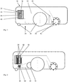
- FIG Figure 1 shows the side sectional view of a robot vacuum 10, as is known from the prior art.
- the suction robot 10 has on its underside 34 at least two wheels 36 with which it can drive autonomously over floor surfaces to be cleaned. At least one of these wheels 36 is driven by a drive device (not shown in FIG Figure 1 ) driven by a motor.
- the vacuum robot 10 On the side 34 of the vacuum robot housing, which faces the floor surface to be cleaned, the vacuum robot 10 has a suction mouth 38. Via this suction mouth 38, the vacuum robot 10 is able to pick up dust and dirt particles from the floor surface and thereby clean them.
- a bristle roller 40 is arranged within the suction mouth 38 of the vacuum robot 10 to enhance the cleaning performance.
- the bristle roller 40 sweeps dust and dirt particles into the suction mouth 38 of the robot vacuum cleaner 10 by means of a rotational movement.
- the bristle roller 40 mobilizes dust and dirt particles which have become lodged in the floor covering, thereby facilitating their extraction.
- the suction mouth 38 is connected to a dust cassette 16 via a suction channel. Via this suction channel 42, the sucked-in and returned dust and dirt particles from the suction mouth 38 into the dust cassette 16, where they are separated and stored by the suction air flow.
- the dust cassette thus acts as the first separation unit. Larger dust and dirt particles are separated from the suction air flow in the dust cassette 16 primarily by gravity.
- a second separation unit 18 is arranged at the outlet of the fine dust cassette 16, where the suction air flow generated by the suction robot 10 exits from it. Through the second separation unit 18 dust and dirt particles are separated from the suction air flow that were not separated by the first separation unit 16. These are primarily particularly fine and light dust and dirt particles.
- the second separation unit 18 is formed by a multi-stage filter element 22, which is composed of a pre-filter 44, a main filter 46 and a post-filter 48.
- the pre-filter 44 consists for example of a foam layer, the main filter 46 made of a pleated filter material and the post-filter 48 made of a fine dust filter material.
- the suction air flow downstream of the second separating unit 18 then flows through the blower of the suction robot (not shown in FIG Figure 1 ) before it is blown out of the housing of the robot vacuum 10 as exhaust air.
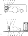
- FIG. 2 shows a side sectional view of a vacuum robot 10 with a rod cleaning device 20 on the second separating unit 18.
- the cleaning device 20 has two rod elements 24 which are in engagement with the prefilter 44 and the main filter 46 of the filter element 22.
- the rod elements 24 perform a translatory movement in and on the filter element 22, which releases fixed dust and dirt particles from the filter element 22. This causes the filter element 22 to be cleaned and extends its service life for the cleaning operation to a significant extent.
- the rod elements 24 of the cleaning device 20 are driven via a camshaft 50, which is connected to the drive device 12 of the vacuum robot 10 via a coupling device 30.
- the camshaft 50 converts the rotational movement of the drive device 12 into a translational movement of the rod elements 24. In this way, the drive device 12 is also used to operate the cleaning device 22.
- FIG. 3 shows a side sectional view of a vacuum robot 10 with a mesh cleaning device 20.
- a three-stage filter element 22 acts as the second separating unit 18.
- a mesh element 26 is arranged in this, which can be set into a translational movement via a camshaft 50.
- the mesh cleaning device 20 transmits a shaking movement to the filter element 22. Dust and dirt particles that have set in the filter material of the filter element 22 are thereby released.
- the camshaft 50 is driven via a coupling device 30, which can be connected to the drive device 12 of the vacuum robot 10. This allows the cleaning device 20 to be operated continuously or partially while the vacuum robot 10 runs autonomously over a floor area.
- FIG. 4 shows a side sectional view of a robot vacuum 10 with a cleaning device 20 which is driven by a second drive device 28.
- a second separate drive device below the second separation unit 18 28 arranged.
- This second drive device 28 is used exclusively to drive the cleaning device 20.
- the vacuum robot 10 has a first drive device 12, which enables the vacuum robot 10 to move over floor surfaces.
- the second drive device 28 drives a rod element 24, which is arranged within the filter element 22, which functions as a second separating unit 18.
- the rod element 24 executes a translatory movement which transfers kinetic energy to the filter element 22.
- dust and dirt particles stored in the filter material of the filter element 22 are mobilized and released.
- a flywheel 52 is arranged between the second drive device 28 and the rod element 24, which converts the rotational movement generated by the drive device 28 into a translational movement of the rod element 24.
- Figure 5 shows a side sectional view of a robot vacuum 10 with a cleaning device 20 which is driven by a second drive device 28.
- the second drive device 28 is arranged laterally next to the second separation unit 18 and drives a rod element 24, which is arranged within the second separation unit 18.
- a filter element 22 acts as a second separation unit 18.
- the rod element 24 is arranged axially along the transverse axis of the filter element 22.
- Mobilization elements 54 are arranged on the rod element 24 itself and extend radially outwards starting from the rod element 24.
- the mobilization elements 54 extend approximately over the entire length of the rod element 24, which is arranged within the filter element 22.
- the mobilization elements 54 are in engagement with the filter material of the filter element 22. If the rod element 24 is set in a rotational movement by the second drive device 28, the mobilization elements 54 transmit this movement impulse to the filter material. As a result of this movement impulse, dust and dirt particles stored in the filter material are released from it.
- FIG. 6 shows a side sectional view of a robot vacuum 10 on a charging station 56.
- the charging station 56 is designed such that it can be driven autonomously by the robot vacuum 10.
- the charging station 56 is designed such that the suction robot 10 orients itself autonomously to the charging station 56 when the charging station 56 is being driven on. This results, among other things, in electrical contact between the charging station 56 and the vacuum robot 10, which causes a charging process for the energy store (not shown in FIG Figure 6 ) of the robot vacuum 10 allowed via the charging station 56.
- the charging station 56 forms a suction channel 58 which forms at least one suction mouth interface 60. This suction mouth interface 60 forms a largely fluid-tight connection to the suction mouth 38 of the vacuum robot 10 when it is on the charging station 56.
- the charging station 56 has a drive device 62 for a cleaning device 20 of the second separation unit 18 of the vacuum robot 10.
- This drive device 62 is connected to an axis 64 which has an interface 66. If the vacuum robot 10 is arranged on the charging station 56, this axis 64, together with the interface 66, dips into the housing of the vacuum robot 10 and establishes a connection with an axis 68 of the cleaning device 20 of the second separation unit 18.
- the movement generated by the drive device 62 in the charging station 56 is transmitted via the interface 66 of the axis 64 to the axis 68 of the cleaning device 20.
- the mesh element 26 of the cleaning device 20 is set into a translatory movement, which causes the second separating unit 18 to be cleaned of dust and dirt particles.
Landscapes
- Engineering & Computer Science (AREA)
- Mechanical Engineering (AREA)
- Electric Vacuum Cleaner (AREA)
Applications Claiming Priority (1)
| Application Number | Priority Date | Filing Date | Title |
|---|---|---|---|
| DE102018114212.9A DE102018114212A1 (de) | 2018-06-14 | 2018-06-14 | Saugroboter und Verfahren zur Steuerung eines Saugroboters |
Publications (2)
| Publication Number | Publication Date |
|---|---|
| EP3581082A1 true EP3581082A1 (fr) | 2019-12-18 |
| EP3581082B1 EP3581082B1 (fr) | 2022-03-02 |
Family
ID=66630175
Family Applications (1)
| Application Number | Title | Priority Date | Filing Date |
|---|---|---|---|
| EP19175820.0A Active EP3581082B1 (fr) | 2018-06-14 | 2019-05-22 | Robot d'aspiration et procédé de commande d'un robot d'aspiration |
Country Status (2)
| Country | Link |
|---|---|
| EP (1) | EP3581082B1 (fr) |
| DE (1) | DE102018114212A1 (fr) |
Cited By (1)
| Publication number | Priority date | Publication date | Assignee | Title |
|---|---|---|---|---|
| EP4400021A4 (fr) * | 2021-09-08 | 2025-10-01 | Positec Power Tools Suzhou Co Ltd | Système de nettoyage et station de base |
Families Citing this family (3)
| Publication number | Priority date | Publication date | Assignee | Title |
|---|---|---|---|---|
| DE102020109656A1 (de) | 2020-04-07 | 2021-10-07 | Alfred Kärcher SE & Co. KG | Filtereinheit für eine Reinigungsmaschine, Boden-Reinigungsmaschine und Verfahren zum Betreiben einer Boden-Reinigungsmaschine |
| DE102020115217A1 (de) * | 2020-06-09 | 2021-12-09 | Miele & Cie. Kg | Saugroboter und Reinigungsstation |
| DE102023201462A1 (de) * | 2023-02-20 | 2024-08-22 | BSH Hausgeräte GmbH | Verfahren zum autonomen Reinigen einer Filtereinrichtung |
Citations (4)
| Publication number | Priority date | Publication date | Assignee | Title |
|---|---|---|---|---|
| EP1913857A2 (fr) * | 2006-10-18 | 2008-04-23 | Kabushiki Kaisha Toshiba | Aspirateur électrique avec deux collecteurs de poussières et un mécanisme de commutation |
| JP2013144036A (ja) * | 2012-01-16 | 2013-07-25 | Sharp Corp | 集塵装置、および掃除機 |
| EP2862490A1 (fr) * | 2013-10-21 | 2015-04-22 | Lg Electronics Inc. | Robot nettoyeur et un procédé permettant de détecter la poussière de celui-ci |
| GB2539934A (en) * | 2015-07-01 | 2017-01-04 | Dyson Technology Ltd | A separating apparatus |
-
2018
- 2018-06-14 DE DE102018114212.9A patent/DE102018114212A1/de not_active Withdrawn
-
2019
- 2019-05-22 EP EP19175820.0A patent/EP3581082B1/fr active Active
Patent Citations (4)
| Publication number | Priority date | Publication date | Assignee | Title |
|---|---|---|---|---|
| EP1913857A2 (fr) * | 2006-10-18 | 2008-04-23 | Kabushiki Kaisha Toshiba | Aspirateur électrique avec deux collecteurs de poussières et un mécanisme de commutation |
| JP2013144036A (ja) * | 2012-01-16 | 2013-07-25 | Sharp Corp | 集塵装置、および掃除機 |
| EP2862490A1 (fr) * | 2013-10-21 | 2015-04-22 | Lg Electronics Inc. | Robot nettoyeur et un procédé permettant de détecter la poussière de celui-ci |
| GB2539934A (en) * | 2015-07-01 | 2017-01-04 | Dyson Technology Ltd | A separating apparatus |
Cited By (1)
| Publication number | Priority date | Publication date | Assignee | Title |
|---|---|---|---|---|
| EP4400021A4 (fr) * | 2021-09-08 | 2025-10-01 | Positec Power Tools Suzhou Co Ltd | Système de nettoyage et station de base |
Also Published As
| Publication number | Publication date |
|---|---|
| EP3581082B1 (fr) | 2022-03-02 |
| DE102018114212A1 (de) | 2019-12-19 |
Similar Documents
| Publication | Publication Date | Title |
|---|---|---|
| EP3581082B1 (fr) | Robot d'aspiration et procédé de commande d'un robot d'aspiration | |
| EP3033983B1 (fr) | Station de base pour un aspirateur | |
| EP4216784B1 (fr) | Dispositif filtrant et son procédé de nettoyage | |
| EP2612582B1 (fr) | Aspirateur et procédé destiné au fonctionnement d'un aspirateur | |
| EP3127461B1 (fr) | Procede de fonctionnement d'un appareil d'aspiration pour surfaces dures et appareil d'aspiration pour surfaces dures destine a executer le procede | |
| DE10302525A1 (de) | Saugvorrichtung eines Reinigers | |
| EP2893860B1 (fr) | Appareil d'entretien du sol doté d'une brosse à rouleaux entraînée | |
| EP1380246A2 (fr) | Aspirateur utilisé à des fins de nettoyage | |
| DE102008026884A1 (de) | Reinigungsgerät für Partikel aufweisende Flächen und Verfahren zu dessen Betrieb | |
| DE102017208963A1 (de) | Eckenreinigungsmodul für modular aufgebaute Reinigungsroboter | |
| DE4330233C2 (de) | Kehrmaschine | |
| EP2644076A1 (fr) | Aspirateur | |
| DE102014108217A1 (de) | Reinigungssystem | |
| WO2021254818A1 (fr) | Dispositif de dépoussiérage pour machine-outil | |
| EP4167820A1 (fr) | Dispositif de collecte de poussière destiné à une machine-outil | |
| DE102020212045B4 (de) | Staubsauger mit Bearbeitungskopf | |
| EP4285799A1 (fr) | Station de base pour appareil de nettoyage, appareil de nettoyage et système | |
| EP3485783B1 (fr) | Aspirateur de sol et procédé de fonctionnement d'un aspirateur de sol | |
| EP4452033A1 (fr) | Unité de nettoyage de filtre, aspirateur et procédé de nettoyage de filtre d'aspirateur | |
| DE102018216306B3 (de) | Verfahren zur Überwachung einer austauschbaren Einheit, sowie Hausgerät mit einer austauschbaren Einheit | |
| EP4449963A1 (fr) | Appareil d'aspiration et son procédé de fonctionnement | |
| EP4039352A1 (fr) | Unité de nettoyage pour un filtre d'un aspirateur, procédé de nettoyage et aspirateur | |
| DE102016105171A1 (de) | Verfahren zum Fahrbetrieb eines selbstfahrenden Bodenreinigungsgeräts | |
| EP4523586A1 (fr) | Dispositif d'aspiration avec deux têtes de ventouse, ainsi que système | |
| EP4650030A1 (fr) | Dispositif et procédé de nettoyage d'un filtre |
Legal Events
| Date | Code | Title | Description |
|---|---|---|---|
| PUAI | Public reference made under article 153(3) epc to a published international application that has entered the european phase |
Free format text: ORIGINAL CODE: 0009012 |
|
| STAA | Information on the status of an ep patent application or granted ep patent |
Free format text: STATUS: REQUEST FOR EXAMINATION WAS MADE |
|
| 17P | Request for examination filed |
Effective date: 20191017 |
|
| AK | Designated contracting states |
Kind code of ref document: A1 Designated state(s): AL AT BE BG CH CY CZ DE DK EE ES FI FR GB GR HR HU IE IS IT LI LT LU LV MC MK MT NL NO PL PT RO RS SE SI SK SM TR |
|
| AX | Request for extension of the european patent |
Extension state: BA ME |
|
| RIC1 | Information provided on ipc code assigned before grant |
Ipc: A47L 9/28 20060101ALI20210916BHEP Ipc: A47L 9/20 20060101ALI20210916BHEP Ipc: A47L 9/12 20060101AFI20210916BHEP |
|
| GRAP | Despatch of communication of intention to grant a patent |
Free format text: ORIGINAL CODE: EPIDOSNIGR1 |
|
| STAA | Information on the status of an ep patent application or granted ep patent |
Free format text: STATUS: GRANT OF PATENT IS INTENDED |
|
| INTG | Intention to grant announced |
Effective date: 20211021 |
|
| GRAS | Grant fee paid |
Free format text: ORIGINAL CODE: EPIDOSNIGR3 |
|
| GRAA | (expected) grant |
Free format text: ORIGINAL CODE: 0009210 |
|
| STAA | Information on the status of an ep patent application or granted ep patent |
Free format text: STATUS: THE PATENT HAS BEEN GRANTED |
|
| REG | Reference to a national code |
Ref country code: DE Ref legal event code: R084 Ref document number: 502019003525 Country of ref document: DE |
|
| AK | Designated contracting states |
Kind code of ref document: B1 Designated state(s): AL AT BE BG CH CY CZ DE DK EE ES FI FR GB GR HR HU IE IS IT LI LT LU LV MC MK MT NL NO PL PT RO RS SE SI SK SM TR |
|
| REG | Reference to a national code |
Ref country code: GB Ref legal event code: FG4D Free format text: NOT ENGLISH |
|
| REG | Reference to a national code |
Ref country code: CH Ref legal event code: EP Ref country code: AT Ref legal event code: REF Ref document number: 1471572 Country of ref document: AT Kind code of ref document: T Effective date: 20220315 |
|
| REG | Reference to a national code |
Ref country code: DE Ref legal event code: R096 Ref document number: 502019003525 Country of ref document: DE |
|
| REG | Reference to a national code |
Ref country code: IE Ref legal event code: FG4D Free format text: LANGUAGE OF EP DOCUMENT: GERMAN |
|
| REG | Reference to a national code |
Ref country code: GB Ref legal event code: 746 Effective date: 20220513 |
|
| REG | Reference to a national code |
Ref country code: LT Ref legal event code: MG9D |
|
| REG | Reference to a national code |
Ref country code: NL Ref legal event code: MP Effective date: 20220302 |
|
| PG25 | Lapsed in a contracting state [announced via postgrant information from national office to epo] |
Ref country code: SE Free format text: LAPSE BECAUSE OF FAILURE TO SUBMIT A TRANSLATION OF THE DESCRIPTION OR TO PAY THE FEE WITHIN THE PRESCRIBED TIME-LIMIT Effective date: 20220302 Ref country code: RS Free format text: LAPSE BECAUSE OF FAILURE TO SUBMIT A TRANSLATION OF THE DESCRIPTION OR TO PAY THE FEE WITHIN THE PRESCRIBED TIME-LIMIT Effective date: 20220302 Ref country code: NO Free format text: LAPSE BECAUSE OF FAILURE TO SUBMIT A TRANSLATION OF THE DESCRIPTION OR TO PAY THE FEE WITHIN THE PRESCRIBED TIME-LIMIT Effective date: 20220602 Ref country code: LT Free format text: LAPSE BECAUSE OF FAILURE TO SUBMIT A TRANSLATION OF THE DESCRIPTION OR TO PAY THE FEE WITHIN THE PRESCRIBED TIME-LIMIT Effective date: 20220302 Ref country code: HR Free format text: LAPSE BECAUSE OF FAILURE TO SUBMIT A TRANSLATION OF THE DESCRIPTION OR TO PAY THE FEE WITHIN THE PRESCRIBED TIME-LIMIT Effective date: 20220302 Ref country code: ES Free format text: LAPSE BECAUSE OF FAILURE TO SUBMIT A TRANSLATION OF THE DESCRIPTION OR TO PAY THE FEE WITHIN THE PRESCRIBED TIME-LIMIT Effective date: 20220302 Ref country code: BG Free format text: LAPSE BECAUSE OF FAILURE TO SUBMIT A TRANSLATION OF THE DESCRIPTION OR TO PAY THE FEE WITHIN THE PRESCRIBED TIME-LIMIT Effective date: 20220602 |
|
| PG25 | Lapsed in a contracting state [announced via postgrant information from national office to epo] |
Ref country code: PL Free format text: LAPSE BECAUSE OF FAILURE TO SUBMIT A TRANSLATION OF THE DESCRIPTION OR TO PAY THE FEE WITHIN THE PRESCRIBED TIME-LIMIT Effective date: 20220302 Ref country code: LV Free format text: LAPSE BECAUSE OF FAILURE TO SUBMIT A TRANSLATION OF THE DESCRIPTION OR TO PAY THE FEE WITHIN THE PRESCRIBED TIME-LIMIT Effective date: 20220302 Ref country code: GR Free format text: LAPSE BECAUSE OF FAILURE TO SUBMIT A TRANSLATION OF THE DESCRIPTION OR TO PAY THE FEE WITHIN THE PRESCRIBED TIME-LIMIT Effective date: 20220603 Ref country code: FI Free format text: LAPSE BECAUSE OF FAILURE TO SUBMIT A TRANSLATION OF THE DESCRIPTION OR TO PAY THE FEE WITHIN THE PRESCRIBED TIME-LIMIT Effective date: 20220302 |
|
| PG25 | Lapsed in a contracting state [announced via postgrant information from national office to epo] |
Ref country code: NL Free format text: LAPSE BECAUSE OF FAILURE TO SUBMIT A TRANSLATION OF THE DESCRIPTION OR TO PAY THE FEE WITHIN THE PRESCRIBED TIME-LIMIT Effective date: 20220302 |
|
| PG25 | Lapsed in a contracting state [announced via postgrant information from national office to epo] |
Ref country code: SM Free format text: LAPSE BECAUSE OF FAILURE TO SUBMIT A TRANSLATION OF THE DESCRIPTION OR TO PAY THE FEE WITHIN THE PRESCRIBED TIME-LIMIT Effective date: 20220302 Ref country code: SK Free format text: LAPSE BECAUSE OF FAILURE TO SUBMIT A TRANSLATION OF THE DESCRIPTION OR TO PAY THE FEE WITHIN THE PRESCRIBED TIME-LIMIT Effective date: 20220302 Ref country code: RO Free format text: LAPSE BECAUSE OF FAILURE TO SUBMIT A TRANSLATION OF THE DESCRIPTION OR TO PAY THE FEE WITHIN THE PRESCRIBED TIME-LIMIT Effective date: 20220302 Ref country code: PT Free format text: LAPSE BECAUSE OF FAILURE TO SUBMIT A TRANSLATION OF THE DESCRIPTION OR TO PAY THE FEE WITHIN THE PRESCRIBED TIME-LIMIT Effective date: 20220704 Ref country code: EE Free format text: LAPSE BECAUSE OF FAILURE TO SUBMIT A TRANSLATION OF THE DESCRIPTION OR TO PAY THE FEE WITHIN THE PRESCRIBED TIME-LIMIT Effective date: 20220302 Ref country code: CZ Free format text: LAPSE BECAUSE OF FAILURE TO SUBMIT A TRANSLATION OF THE DESCRIPTION OR TO PAY THE FEE WITHIN THE PRESCRIBED TIME-LIMIT Effective date: 20220302 |
|
| PG25 | Lapsed in a contracting state [announced via postgrant information from national office to epo] |
Ref country code: IS Free format text: LAPSE BECAUSE OF FAILURE TO SUBMIT A TRANSLATION OF THE DESCRIPTION OR TO PAY THE FEE WITHIN THE PRESCRIBED TIME-LIMIT Effective date: 20220702 Ref country code: AL Free format text: LAPSE BECAUSE OF FAILURE TO SUBMIT A TRANSLATION OF THE DESCRIPTION OR TO PAY THE FEE WITHIN THE PRESCRIBED TIME-LIMIT Effective date: 20220302 |
|
| REG | Reference to a national code |
Ref country code: DE Ref legal event code: R097 Ref document number: 502019003525 Country of ref document: DE |
|
| REG | Reference to a national code |
Ref country code: CH Ref legal event code: PL |
|
| PLBE | No opposition filed within time limit |
Free format text: ORIGINAL CODE: 0009261 |
|
| STAA | Information on the status of an ep patent application or granted ep patent |
Free format text: STATUS: NO OPPOSITION FILED WITHIN TIME LIMIT |
|
| REG | Reference to a national code |
Ref country code: BE Ref legal event code: MM Effective date: 20220531 |
|
| PG25 | Lapsed in a contracting state [announced via postgrant information from national office to epo] |
Ref country code: MC Free format text: LAPSE BECAUSE OF FAILURE TO SUBMIT A TRANSLATION OF THE DESCRIPTION OR TO PAY THE FEE WITHIN THE PRESCRIBED TIME-LIMIT Effective date: 20220302 Ref country code: LU Free format text: LAPSE BECAUSE OF NON-PAYMENT OF DUE FEES Effective date: 20220522 Ref country code: LI Free format text: LAPSE BECAUSE OF NON-PAYMENT OF DUE FEES Effective date: 20220531 Ref country code: DK Free format text: LAPSE BECAUSE OF FAILURE TO SUBMIT A TRANSLATION OF THE DESCRIPTION OR TO PAY THE FEE WITHIN THE PRESCRIBED TIME-LIMIT Effective date: 20220302 Ref country code: CH Free format text: LAPSE BECAUSE OF NON-PAYMENT OF DUE FEES Effective date: 20220531 |
|
| 26N | No opposition filed |
Effective date: 20221205 |
|
| PG25 | Lapsed in a contracting state [announced via postgrant information from national office to epo] |
Ref country code: SI Free format text: LAPSE BECAUSE OF FAILURE TO SUBMIT A TRANSLATION OF THE DESCRIPTION OR TO PAY THE FEE WITHIN THE PRESCRIBED TIME-LIMIT Effective date: 20220302 |
|
| PG25 | Lapsed in a contracting state [announced via postgrant information from national office to epo] |
Ref country code: IE Free format text: LAPSE BECAUSE OF NON-PAYMENT OF DUE FEES Effective date: 20220522 |
|
| PG25 | Lapsed in a contracting state [announced via postgrant information from national office to epo] |
Ref country code: BE Free format text: LAPSE BECAUSE OF NON-PAYMENT OF DUE FEES Effective date: 20220531 |
|
| P01 | Opt-out of the competence of the unified patent court (upc) registered |
Effective date: 20230528 |
|
| PG25 | Lapsed in a contracting state [announced via postgrant information from national office to epo] |
Ref country code: MK Free format text: LAPSE BECAUSE OF FAILURE TO SUBMIT A TRANSLATION OF THE DESCRIPTION OR TO PAY THE FEE WITHIN THE PRESCRIBED TIME-LIMIT Effective date: 20220302 Ref country code: CY Free format text: LAPSE BECAUSE OF FAILURE TO SUBMIT A TRANSLATION OF THE DESCRIPTION OR TO PAY THE FEE WITHIN THE PRESCRIBED TIME-LIMIT Effective date: 20220302 |
|
| PG25 | Lapsed in a contracting state [announced via postgrant information from national office to epo] |
Ref country code: HU Free format text: LAPSE BECAUSE OF FAILURE TO SUBMIT A TRANSLATION OF THE DESCRIPTION OR TO PAY THE FEE WITHIN THE PRESCRIBED TIME-LIMIT; INVALID AB INITIO Effective date: 20190522 |
|
| PG25 | Lapsed in a contracting state [announced via postgrant information from national office to epo] |
Ref country code: TR Free format text: LAPSE BECAUSE OF FAILURE TO SUBMIT A TRANSLATION OF THE DESCRIPTION OR TO PAY THE FEE WITHIN THE PRESCRIBED TIME-LIMIT Effective date: 20220302 |
|
| PG25 | Lapsed in a contracting state [announced via postgrant information from national office to epo] |
Ref country code: MT Free format text: LAPSE BECAUSE OF FAILURE TO SUBMIT A TRANSLATION OF THE DESCRIPTION OR TO PAY THE FEE WITHIN THE PRESCRIBED TIME-LIMIT Effective date: 20220302 |
|
| PGFP | Annual fee paid to national office [announced via postgrant information from national office to epo] |
Ref country code: DE Payment date: 20250531 Year of fee payment: 7 |
|
| PGFP | Annual fee paid to national office [announced via postgrant information from national office to epo] |
Ref country code: IT Payment date: 20250522 Year of fee payment: 7 |
|
| REG | Reference to a national code |
Ref country code: AT Ref legal event code: MM01 Ref document number: 1471572 Country of ref document: AT Kind code of ref document: T Effective date: 20240522 |
|
| PGFP | Annual fee paid to national office [announced via postgrant information from national office to epo] |
Ref country code: FR Payment date: 20250526 Year of fee payment: 7 |
|
| PG25 | Lapsed in a contracting state [announced via postgrant information from national office to epo] |
Ref country code: AT Free format text: LAPSE BECAUSE OF NON-PAYMENT OF DUE FEES Effective date: 20240522 |
|
| PGFP | Annual fee paid to national office [announced via postgrant information from national office to epo] |
Ref country code: GB Payment date: 20260313 Year of fee payment: 8 |
|
| PGFP | Annual fee paid to national office [announced via postgrant information from national office to epo] |
Ref country code: AT Payment date: 20260410 Year of fee payment: 5 |