EP3581284A1 - Dispositif et procédé de distribution d'un fluide - Google Patents
Dispositif et procédé de distribution d'un fluide Download PDFInfo
- Publication number
- EP3581284A1 EP3581284A1 EP18177568.5A EP18177568A EP3581284A1 EP 3581284 A1 EP3581284 A1 EP 3581284A1 EP 18177568 A EP18177568 A EP 18177568A EP 3581284 A1 EP3581284 A1 EP 3581284A1
- Authority
- EP
- European Patent Office
- Prior art keywords
- fluid
- actuating
- actuation
- designed
- actuating member
- Prior art date
- Legal status (The legal status is an assumption and is not a legal conclusion. Google has not performed a legal analysis and makes no representation as to the accuracy of the status listed.)
- Granted
Links
Images



Classifications
-
- B—PERFORMING OPERATIONS; TRANSPORTING
- B08—CLEANING
- B08B—CLEANING IN GENERAL; PREVENTION OF FOULING IN GENERAL
- B08B3/00—Cleaning by methods involving the use or presence of liquid or steam
- B08B3/02—Cleaning by the force of jets or sprays
- B08B3/026—Cleaning by making use of hand-held spray guns; Fluid preparations therefor
-
- B—PERFORMING OPERATIONS; TRANSPORTING
- B05—SPRAYING OR ATOMISING IN GENERAL; APPLYING FLUENT MATERIALS TO SURFACES, IN GENERAL
- B05B—SPRAYING APPARATUS; ATOMISING APPARATUS; NOZZLES
- B05B12/00—Arrangements for controlling delivery; Arrangements for controlling the spray area
- B05B12/002—Manually-actuated controlling means, e.g. push buttons, levers or triggers
-
- B—PERFORMING OPERATIONS; TRANSPORTING
- B05—SPRAYING OR ATOMISING IN GENERAL; APPLYING FLUENT MATERIALS TO SURFACES, IN GENERAL
- B05B—SPRAYING APPARATUS; ATOMISING APPARATUS; NOZZLES
- B05B12/00—Arrangements for controlling delivery; Arrangements for controlling the spray area
- B05B12/08—Arrangements for controlling delivery; Arrangements for controlling the spray area responsive to condition of liquid or other fluent material to be discharged, of ambient medium or of target ; responsive to condition of spray devices or of supply means, e.g. pipes, pumps or their drive means
-
- B—PERFORMING OPERATIONS; TRANSPORTING
- B08—CLEANING
- B08B—CLEANING IN GENERAL; PREVENTION OF FOULING IN GENERAL
- B08B2203/00—Details of cleaning machines or methods involving the use or presence of liquid or steam
- B08B2203/007—Heating the liquid
-
- B—PERFORMING OPERATIONS; TRANSPORTING
- B08—CLEANING
- B08B—CLEANING IN GENERAL; PREVENTION OF FOULING IN GENERAL
- B08B2203/00—Details of cleaning machines or methods involving the use or presence of liquid or steam
- B08B2203/02—Details of machines or methods for cleaning by the force of jets or sprays
- B08B2203/0282—Safety devices
-
- B—PERFORMING OPERATIONS; TRANSPORTING
- B08—CLEANING
- B08B—CLEANING IN GENERAL; PREVENTION OF FOULING IN GENERAL
- B08B2230/00—Other cleaning aspects applicable to all B08B range
- B08B2230/01—Cleaning with steam
-
- B—PERFORMING OPERATIONS; TRANSPORTING
- B08—CLEANING
- B08B—CLEANING IN GENERAL; PREVENTION OF FOULING IN GENERAL
- B08B3/00—Cleaning by methods involving the use or presence of liquid or steam
- B08B3/02—Cleaning by the force of jets or sprays
- B08B3/026—Cleaning by making use of hand-held spray guns; Fluid preparations therefor
- B08B3/028—Spray guns
Definitions
- the present invention relates to a device for dispensing a fluid, in particular for dispensing superheated steam, hot water or a liquid under low or high pressure, which device comprises a fluid inlet, a fluid outlet which is fluidly connected to the fluid inlet via a fluid connection, and a valve device, which valve device is arranged or designed between the fluid inlet and the fluid outlet for opening the fluid connection between the fluid inlet and the fluid outlet in an open position and for closing the fluid connection in a closed position, which device further comprises an actuating device for transferring the valve device from the open position into the closed position and vice versa , wherein the actuating device comprises at least a first actuator.
- the present invention relates to a method for dispensing a fluid with a device, in particular for dispensing superheated steam, hot water or a liquid under low or high pressure, which device comprises a fluid inlet and a fluid outlet which is fluidly connected to the fluid inlet via a fluid connection, which Fluid connection is opened for dispensing the fluid and which fluid connection is closed to prevent dispensing of the fluid, which device further comprises an actuating device for opening and closing the fluid connection, wherein the actuating device comprises at least a first actuating member.
- Devices of the type described at the outset are known in many different ways. For example, they are used as steam cleaning devices or high-pressure cleaning devices to deliver superheated steam or a cleaning liquid, in particular water, under high pressure.
- a problem with devices of the type described in the introduction is in particular that the dispensing of the fluid should not only stop automatically, but rather must stop when a user releases the device or a part thereof. In the case of known devices, this is realized, for example, in such a way that, as a rule, an actuating member must be kept permanently actuated. If the actuator is no longer actuated, for example released, the valve device automatically switches to the closed position in order to prevent the fluid from being released. This is particularly important if the fluid to be dispensed carries the risk of injuring people or damaging devices, as is the case in particular in the case of uncontrolled dispensing of hot steam, hot water or liquids under high pressure.
- the actuating device comprises at least one second actuating member and one actuating detection device which is connected for control purposes to the at least one first actuating member and the at least one second actuating member and which is designed to detect actuation of the at least one first actuating member and the at least one second actuating member, and that the actuating device is designed to transfer the valve device from the closed position into the open position only if the actuation detection device detects actuation of the at least one second actuation element, while the actuation detection device detects actuation of the at least one first actuation element.
- the further development proposed according to the invention makes it possible in particular for a user to hold the device and, for example, to actuate the at least one first actuating member. During such an actuation of the at least one first actuating element, he can then open the fluid connection by actuating the at least one second actuating element. In particular, it is not necessary to permanently actuate the second actuating member in order to hold the valve device in the open position. A simple actuation of the at least one second actuator is sufficient for this. For example, a fluid can be dispensed for a user without great effort. Operational reliability of the device is ensured in particular in that the fluid connection can only be opened when the at least one first actuating element is actuated.
- the actuating device must therefore first detect an actuation of the at least one first actuating member and only transfers the valve device, which can comprise a solenoid valve, for example, from the closed position into the open position when the at least one second actuating member is actuated during the actuation of the at least one first actuating member is detected.
- the valve device which can comprise a solenoid valve, for example, from the closed position into the open position when the at least one second actuating member is actuated during the actuation of the at least one first actuating member is detected.
- a particularly safe handling of the device can be achieved in particular in that the at least one first actuation element is designed in the form of a user recognition element.
- a user recognition element serves in particular the purpose of reliably recognizing whether the device is actually being held or operated by a user. In this way it can in particular be ensured that the opening of the fluid connection between the fluid inlet and the fluid outlet is actually only possible if the first actuating element detects a user.
- the at least one second actuating element is designed in the form of a valve actuating element.
- the at least one second actuating element therefore serves in particular the purpose of actuating the valve device, that is to say for example moving it from the closed position into the open position and / or vice versa.
- the second actuator can perform this function, that the first actuator is permanently operated by a user.
- the at least one second actuating element makes it possible, in particular, to selectively activate or deactivate the valve device, that is to say to selectively open or close the fluid connection, wherein permanent actuation of the at least one second actuating element is not necessary.
- the actuating device is designed to transfer the valve device from the open position into the closed position as soon as the actuation detection device no longer detects actuation of the at least one first actuating member.
- a handle in the sense of this application is to be understood in particular to mean everything that a user can grasp and hold with his hand in order to handle the device. In particular, this also includes the entire device if it is made sufficiently small. In this sense, for example, a computer mouse as a whole forms a handle due to its shape and size.
- the actuating device is designed to transfer the valve device from the open position into the closed position if the actuation detection device detects an actuation of the at least one second actuating element, while the actuating device detects an actuation of the at least one first actuating element.
- the actuation detection device detects an actuation of the at least one second actuating element
- the actuating device detects an actuation of the at least one first actuating element.
- a continuous dispensing function of the device for dispensing the fluid can be implemented, only the at least one first actuating element having to be actuated for this.
- the fluid delivery can be switched on and off again by selective actuation of the at least one second actuating element.
- the prerequisite is that the at least one first actuating element is already actuated at the time the at least one second actuating element is actuated.
- the actuating device is designed to prevent or block a transfer of the valve device from the closed position into the open position if the actuation detection device does not detect actuation of the at least one first actuation element.
- the at least one first actuating element is designed as a user recognition element, the delivery of a fluid can be effectively prevented if the at least one first actuating element is not actuated.
- the device can optionally also be a blocking or blocking device for Block a function of the actuating device and / or the valve device include.
- the at least one first actuator and / or the at least one second actuator can be used as input elements in order to enter an activation code.
- further input elements can be provided in order to enter a security or unlock code in order to be able to activate the device. This can prevent unauthorized use or activation of the device.
- first actuators In principle, it is possible to provide two, three or more first actuators. It is also possible to provide two, three or more second actuators.
- the device In order to be able to ensure a defined handling of the device, however, it can also be advantageous if the device comprises only a single first actuating element and / or only a single second actuating element.
- the at least one first actuating member and / or the at least one second actuating member are designed in the form of an electronic switching element. All types of electronic switching elements which are suitable for determining actuation, for example by touching, exerting pressure or detecting heat, are conceivable here. This list of possible ways of detecting the presence of a user's hand is not exhaustive.
- the electronic switching element is designed to be bounce-free.
- the functionality of the device can in particular be achieved with a high level of security, since incorrect operation, in particular due to unintentional multiple actuation, for example of the at least one second actuator, can be prevented.
- the electronic switching element is preferably designed in the form of a mechanical switch or in the form of a capacitive sensor button.
- Mechanical switches or switching elements can be operated by applying pressure.
- a capacitive sensor button has the particular advantage that no pressure is required. Touching or simply the presence of, for example, a hand of a user is sufficient to generate an actuation signal which can be detected and optionally evaluated in particular by the actuation detection device.
- a capacitive sensor button can in particular also be covered with a protective layer or arranged within a housing of the device.
- a position of the capacitive sensor button can be displayed to a user in particular by means of a coloring or a special shape of the device. For example, such a capacitive sensor button can be arranged on a device area that a user must always touch when using the device for dispensing a fluid, for example on a handle.
- the at least one second actuation element is designed to generate an actuation signal and if the actuation detection device is designed to detect the actuation signal.
- This further development makes it possible, in particular, to be able to reliably detect actuation of the at least one second actuating member.
- the at least one second actuating element is designed to generate the actuating signal in the form of a rising switching edge or in the form of a falling switching edge as a result of an actuation of the at least one second actuating element.
- a rising switching edge can be generated in particular when the unactuated actuator is actuated, a falling switching edge when actuation of the at least one second actuator is canceled.
- the at least one second actuator does not have to be actuated continuously in order to keep the valve device in the open position.
- a simple brief actuation of the at least one second actuating element optionally generates a rising switching edge or a falling switching edge, one or both of which can be used to be detected as an actuation signal by the actuation detection device.
- the at least one first actuating element and the at least one second actuating element are arranged or designed on the device in such a way that one-hand operation thereof is possible.
- a one-hand operation means in particular that a user can grasp the device with one hand and at the same time, if necessary, can actuate the at least one first actuating element and the at least one second actuating element simultaneously.
- the actuators are arranged such that a user can hold the device and then selectively actuate in particular the at least one second actuator.
- the at least one first actuating element defines a first touch-sensitive actuating surface and / or if the at least one second actuating element defines a second touch-sensitive actuating surface.
- the at least one first actuating element and / or the at least one second actuating element can be actuated.
- the second touch-sensitive actuation area is smaller than the first touch-sensitive actuation area.
- the risk of incorrect operation of the device can be minimized.
- a larger, in particular significantly larger, first touch-sensitive actuating surface in comparison to the second touch-sensitive actuating surface can in particular ensure that user recognition is guaranteed with great certainty. In this case, it does not matter to a user whether he is touching the device at a specific point or not. Rather, a defined touch is desired for the second touch-sensitive actuation surface. To specify this, it is preferably smaller than the first touch-sensitive actuation area.
- first touch-sensitive actuating surface and the second touch-sensitive actuating surface are arranged on the device in a spatially separated manner.
- the device has a handle and that the handle and the fluid outlet are arranged in a defined spatial relationship to one another.
- a handle and that the handle and the fluid outlet are arranged in a defined spatial relationship to one another.
- Such a configuration enables a user in particular to use the device in a targeted manner and to dispense the fluid in the desired manner and in particular in a desired direction.
- this arrangement enables him to position and orient the fluid outlet in the desired manner by holding and guiding the handle.
- the device can also form the handle as a whole, for example when it is designed to be small enough to be held in the hand of a user, similar to a computer mouse.
- the handle and the fluid outlet are connected to one another directly or indirectly.
- they can be immovably connected to one another.
- the device can comprise a housing on which both the handle and the fluid outlet are arranged.
- the handle and the fluid outlet can be arranged or formed on a high-pressure gun, which is also referred to as a gun handle.
- a simple handling of the device for a user is possible in particular in that the at least one first actuator and the at least one second actuator is arranged or formed on the handle. If a user grips the handle, he can in particular automatically actuate the at least one first actuating element. If the at least one second actuation element is arranged accordingly, it can actuate this by moving one of its fingers and positioning it on the at least one second actuation element and thus, for example, transfer the valve device from the closed position into the open position or vice versa.
- the arrangement of the actuators on the handle enables simple operation of the device.
- the handle has a handle area for holding the handle with one hand and if the at least one first actuating element is arranged or designed on the handle area.
- the first actuator in particular as a user recognition element. Only when a user grasps or touches the handle on the grip area is the at least one first actuating element actuated and then enables the valve device to be activated in order to open the fluid connection between the fluid inlet and the fluid outlet.
- the device comprises a fluid reservoir or if the fluid inlet is designed to be connectable to a fluid reservoir or a fluid source.
- This configuration makes it possible, in particular, to operate the device independently, that is to say far from a fluid source.
- the fluid inlet is designed in the form of a fluid connection, the device can be connected to a fluid reservoir or a fluid source. This enables, in particular, continuous operation of the device, since fluid is continuously provided for dispensing.
- the device comprises a heating device for heating the fluid to be dispensed.
- a pressure washer can also be used comprise a heating device in order to heat the fluid to be released under pressure and thus to achieve even better cleaning results.
- the heating device can be used, for example, to heat water as the fluid to be dispensed, so that it can be dispensed as hot water by the device.
- the heating device can in particular be designed in the form of a continuous-flow heater. In this case in particular, it is advantageous if the device comprises a pump in order to convey the fluid into the water heater.
- the heating device is preferably designed in the form of an evaporation device for evaporating the fluid.
- superheated steam can be generated if water is heated above the evaporation temperature.
- the evaporation device can be designed in the form of a steam boiler.
- the device is designed in the form of a steam cleaning device.
- the device comprises a pressure pump for generating a fluid pressure in the fluid to be dispensed.
- a pressure pump for generating a fluid pressure in the fluid to be dispensed. This makes it possible, in particular, to pressurize surfaces to be cleaned with the fluid to be released, in order to be able to mechanically remove soiling.
- the pressure pump is preferably designed to generate a fluid pressure which is higher than the pressure prevailing in the fluid before the pressure pump flows through.
- the pressure pump is preferably designed to generate a fluid pressure of at least 3 bar, in particular of at least 5 bar.
- the pressure pump is advantageously designed in the form of a high-pressure pump for generating a fluid pressure of at least 50 bar, in particular of at least 100 bar.
- a device with such a pressure pump enables cleaning of surfaces, in particular in a simple and fluid-saving manner.
- the device is advantageously designed in the form of a high-pressure cleaning device.
- a high-pressure cleaning device makes it possible, in particular, to pressurize surfaces to be cleaned with a fluid under pressure, as a result of which dirt can be removed by mechanical processing, namely by blasting.
- the device comprises a control and / or regulating device for controlling and / or regulating a volume flow of the fluid to be dispensed and / or a physical quantity of the fluid.
- the physical size of the fluid can in particular be pressure and temperature in the fluid.
- a pressure and / or a temperature and a volume flow of the fluid to be dispensed can be specified independently of one another and in the desired manner.
- control and / or regulating device is designed to specify one or more discrete values of the volume flow of the fluid to be dispensed or to infinitely specify the volume flow.
- control and / or regulating device can be designed to simply activate and deactivate the volume flow.
- a volume flow can then be specified in particular by a cross section of the fluid outlet.
- a continuous variation of the volume flow has the particular advantage that only as much fluid has to be dispensed as is actually required.
- a particularly compact construction of the device can in particular be achieved in that the control and / or regulating device comprises the actuating device.
- the control and / or regulating device can in particular with the at least one first actuator and / or cooperate with the at least one second actuating element in order to specifically lock or unlock the device by entering a locking or unlocking code, for example by specifically actuating the at least one first actuating element and / or the at least one second actuating element in a predetermined sequence for locking or unlocking and / or duration of operation.
- the control and / or regulating device can in particular form part of a safety device, which is activated, for example, in a basic position and must first be deactivated specifically by a user in order to enable fluid to be dispensed.
- the securing device can comprise at least one further securing member with which the actuating device, in particular the at least one first actuating member and / or the at least one second actuating member, can be specifically deactivated or reactivated, for example in order to inadvertently or unauthorized activation of the device, in particular the To prevent fluid release.
- the device comprises a display device for displaying at least one operating state of the device.
- the display device can indicate whether the valve device is in the open position and / or the closed position.
- it can also be displayed in particular whether, for example, a heating device or a pressure pump is activated or not.
- several and different operating states can also be displayed in time.
- the display device can in particular comprise a corresponding number of display elements.
- the display device is preferably designed to display an operating state which is assigned to the open position of the valve device. In particular, this enables a user of the device to directly recognize, for example optically or acoustically, whether the fluid connection between the fluid inlet and the fluid outlet is open or not.
- valve device can also be designed to open and close the fluid outlet. Neither the fluid inlet nor the fluid outlet necessarily have to form connections of the device which are immediately visible to the user.
- the fluid inlet and the fluid outlet can in particular also be connections of the valve device, which can then be connected via corresponding further fluid connections to a fluid connection for connection, for example to a fluid reservoir or a fluid source, or to a fluid discharge nozzle.
- the display device is designed in the form of an optical and / or acoustic display device for optical and / or acoustic display of the at least one operating state of the device.
- a user can be optically and / or acoustically signaled in which operating state the device is, whether or not fluid is being dispensed or whether one or more additional devices of the devices are active or not.
- the device can be of simple and compact design, in particular, if the display device comprises at least one lighting element and / or at least one acoustic signal transmitter.
- the acoustic signal generator can be designed in particular in the form of a loudspeaker.
- the at least one light-emitting element can be designed in particular in the form of a light-emitting diode or in the form of a display.
- the optical display device is arranged or formed on the device in spatial proximity to the at least one actuating element.
- the optical display device can be arranged or formed adjacent or directly adjacent to the at least one second actuating element.
- the actuating device comprises at least one second actuator and that to open the fluid connection, the at least one second actuator is actuated while the at least one first actuator is actuated.
- a permanent function for dispensing the fluid can also be implemented without the user having to permanently actuate the at least one second actuating element.
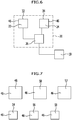
- An exemplary embodiment of a device 10 for dispensing a fluid comprises a fluid inlet 12 and a fluid outlet 14.
- the fluid inlet 12 and the fluid outlet 14 are fluidly connected to one another via a fluid connection 16.
- a valve device 18 is arranged between the fluid inlet 12 and the fluid outlet 14 or is designed to open the fluid connection 16 in an open position and for closing the fluid connection 16 in a closed position.
- the device 10 further comprises an actuating device 20 for transferring the valve device 18 from the open position into the closed position and vice versa.
- the actuating device 20 comprises a first actuating element 22 and a second actuating element 24.
- the actuation device 20 comprises an actuation detection device 26 which is connected to the first actuation element and to the second actuation element 24 in a control-effective manner via connecting lines 28 and 30.
- the actuation detection device 26 is designed to detect actuation of the first actuation element 22 and the second actuation element 24.
- the actuation device 20 is also designed to transfer the valve device 18 from the closed position into the open position only when the actuation detection device 26 detects an actuation of the second actuation element 24, while the actuation detection device 26 also detects an actuation of the first actuation element 22.
- actuator 20 includes two or more first actuators 22.
- the actuating device 20 comprises two or more second actuators 24.
- the number of the first actuators 22 and the second actuators 24 can be provided as desired.
- the first actuating element is designed in the form of a user identification element 32.
- the user recognition element 32 serves in particular the purpose of determining whether the device 10 is used by an operator or not. It is therefore recognized whether a user actuates the first actuating member 22.
- the second actuating element 24 is designed in the form of a valve actuating element 34.
- a user can actuate the valve device 18, provided that the first actuating element 22 has already been actuated.
- the actuating device 20 is designed to transfer the valve device 18 from the open position into the closed position as soon as the actuation detection device 26 no longer detects actuation of the first actuating member 22.
- the actuation device 20 is designed such that it transfers the valve device 18 from the open position to the closed position when the actuation detection device 26 detects an actuation of the second actuation element 24, while the actuation detection device 26 detects an actuation of the first actuation element 22.
- the actuating device 20 is designed such that it prevents or blocks the valve device 18 from being moved from the closed position into the open position if the actuation detection device does not detect actuation of the first actuating member 22.
- the actuating device 20 comprises a single first actuating element 22 and a single second actuating element 24.
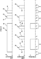
- the actuating device 20 is in particular designed to accommodate the six in Figure 3 to realize schematically represented operating states A, B, C, D, E and F.
- FIG. 3 An actuation of the first actuating member 22, an actuation of the second actuating member 24 and a position of the valve device 18 are shown one above the other.
- the value 0 indicates the position "not actuated” for the actuators 22 and 24, the value 1 indicates the position "actuated”.
- the value 0 for the valve device corresponds to the closed position, the value 1 for the open position.
- the first actuator 22 is actuated.
- the valve device 18 remains in the closed position until time t 2 , in which the second actuating member 24 is actuated.
- a rising switching edge 36 of an actuation signal 38 generated by the second actuating element 24 is detected by the actuation detection device 26 and activates the valve device 18, i.e. transfers it at the time t 2 from the closed position to the open position.
- valve device 18 remains in the open position until the second actuating member 24 is actuated again and an actuating signal 38 with a rising switching edge 36 generated, which is detected by the actuation detection device 26.
- the fluid connection 16 is thus closed by the valve device 18.
- valve device 18 assumes the operating state B, that is to say the open position.
- the actuation detection device 26 detects the rising switching edge 36 of the actuation signal 38. Since the first actuating element 22 was already actuated before the actuation of the second actuating element 24 and is still actuated , the valve device is transferred from the closed position to the open position again at time t 6 .
- the valve device 18 can be transferred from the open position back to the closed position by a further rising switching edge 36 of a further actuation signal 34 of the second actuation element 24, as is the case at time t 4 and has already been described.
- the special safety function of the device 10 leads to a transition of the valve device 18 from the open position into the closed position even if the actuation of the first actuating member 22 is canceled at time t 8 .
- a falling switching edge 44 of the actuation signal 42, which is detected by the actuation detection device 26 leads to the immediate transfer of the valve device 18 from the open position to the closed position at time t 8 .
- the fluid connection 16 is therefore closed when either an actuation of the first actuating element 22 is canceled or when the actuation of the first actuating element 22 continues, the second actuating element 24 is actuated again.
- valve device 18 remains in the closed position.
- the valve device 18 nevertheless remains in the closed position.
- the prerequisite for actuating the valve device 18 is not met, namely that the first actuating element 22 must already be actuated when the second actuating element 24 is actuated.
- both the cancellation of the actuation of the first actuating member 22 and of the second actuating member 24 at time t 11 does not lead to any change in the operating state of the valve device 18.
- valve device remains in the closed position.
- valve device 18 also remains in the closed position, even if the actuation of the second actuating element 24 is canceled at time t 15 .
- valve device 18 assumes operating state C.
- the fluid connection 16 is open, the valve device 18 assumes the open position.
- the special point in time t 8 is that the valve device 18 is automatically transferred from the open position into the closed position when the actuation of the first actuating member 22 is canceled.
- the falling switching edge 44 of the actuation signal 42 of the first actuation element 22 thus defines an automatic “OFF” function of the device 10.
- the dispensing of the fluid is automatically interrupted as soon as actuation of the first actuating member 22 is canceled. If the first actuating member 22 is designed as a user recognition member 32, the removal of the recognition of a user who operates the device 10 automatically leads to the interruption of the dispensing of the fluid, namely by closing the fluid connection 16 by moving the valve device 18 from the open position into the closed position.
- the operating state E between the time t 12 and the time t 13 also corresponds to the closed position of the valve device 18.
- Operating state F between times t 14 and t 15 also corresponds to the closed position of valve device 18.
- the non-actuation of the first actuating member 22 blocks the activation of the valve device 18, that is to say the opening of the fluid connection 16. This ensures that the valve device 18 can only assume the open position when the first actuating member 22 is actuated.
- the first actuator 22 and the second actuator 24 are formed in one embodiment in the form of an electronic switching element 46.
- the electronic switching element 46 is in the form of a bounce-free electronic switching element 46.
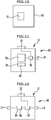
- the electronic switching element 46 can be in the form of a mechanical switch or button 48, for example in the form of a microswitch, in the form of a capacitive sensor button 50, in the form of an ultrasonic proximity sensor 52, in the form of a radar sensor 54, in the form of a forked light barrier 56 or in In the form of a reflected light button 58 may be formed.
- the geometries shown are purely exemplary.
- the electronic switching elements 46 can in particular be implemented in any geometries, for example they can be flat or three-dimensionally curved, oval, circular, polygonal or have any edge contour.
- the second actuation member 24 is designed to generate an actuation signal 38 which can be detected with the actuation detection device 26.
- the second actuating element 24 is designed to generate an actuating signal 38 with a rising switching edge 36 or an actuating signal in the form of a rising switching edge 36 or an actuating signal in the form of a falling switching edge 40 as a result of actuation of the second actuating element 24 ,
- the first actuating element 22 is spatially assigned to the second actuating element 24, for example in the case of a handle 60 of the device 10.
- the handle 60 defines a handle area 62 for holding the handle 60 with one hand of a user.
- the first actuator 22 is arranged on the grip area 62.
- the second actuating element 24 is also arranged or formed on the grip area 62 or on the handle 60, this enables a user to operate with one hand in a simple manner, since he can use both the first actuating element 22 and the second with one hand or the fingers of his hand Contact actuator 24 and can operate.
- the device 10 forms the handle 60 as a whole, namely in that it is designed to be small enough to be held in the hand of a user as a whole, similar to a computer mouse.
- the first actuating member 22 defines a first touch-sensitive actuating surface 64.
- the second actuating member 24 defines a second touch-sensitive actuating surface 66.
- the second touch-sensitive actuation surface 66 is smaller than the first touch-sensitive actuation surface 64.
- first touch-sensitive actuation surface 64 and the second touch-sensitive actuation surface 66 are arranged spatially separated from one another on the device 10.
- the handle 60 and the fluid outlet 12 are in a defined spatial relationship to one another. In particular, they are immovably connected directly or indirectly to one another.
- the fluid inlet 12 can be connected to a fluid reservoir 70 or a fluid source 68 via a connecting line 68.
- the fluid reservoir 70 can be a tank 74, in particular a water tank.
- the fluid source 72 can in particular be a water connection 76 of a water supply network, a water source, a stream or a lake.
- the device 10 itself comprises a fluid store 70.
- the device 10 can thus be operated independently of a water supply network.
- a heating device 78 is provided for heating the fluid to be dispensed.
- the heating device 78 can be arranged to heat the fluid contained in the fluid reservoir 70 of the device 10.
- the heating device can be used, in particular, to heat water, for example to a temperature below the boiling point. The water heated in this way can be released with the device in the form of so-called hot water.
- the heating device 78 is designed in the form of a continuous-flow heater, which in particular makes it possible to heat fluid flowing in from a fluid reservoir or a fluid source 76, which fluid is conveyed, for example, by a pump.
- the heating device 78 is in the form of an evaporation device 80 for evaporating the fluid.
- the device 10 forms a steam cleaning device 82.
- the device 10 comprises a pressure pump 84 for generating a fluid pressure in the fluid to be dispensed.
- the pressure pump 84 is designed to generate a fluid pressure which is higher than the pressure prevailing in the fluid before the pressure pump 84 flows through. In one embodiment, the pressure pump 84 is designed to generate a fluid pressure of at least 3 bar, in particular at least 5 bar.
- the pressure pump 84 is designed in the form of a high-pressure pump 86 for generating a fluid pressure of at least 100 bar. In this way, a high-pressure cleaning device 88 can be formed overall.
- a further exemplary embodiment of a device 10 comprises a control and / or regulating device 90 for controlling and / or regulating a volume flow of the fluid to be dispensed and / or a physical quantity of the fluid, in particular pressure and temperature.
- control and / or regulating device 90 is designed to specify one or more discrete values of the volume flow of the fluid to be dispensed.
- control and / or regulating device 90 is designed for the stepless specification of a volume flow.
- control and / or regulating device 90 comprises the actuating device 20 in a further exemplary embodiment of the device 10.
- An embodiment of the device 10 further comprises a display device 92 for displaying at least one operating state of the device 10.
- the display device 92 is designed to display an operating state which is assigned to the open position of the valve device 18.
- the display device 92 could display the operating states B and C, as exemplified in FIG Figure 3 are marked.
- the display device 92 is designed in the form of an optical and / or acoustic display device 92 for the optical and / or acoustic display of the at least one operating state of the device 10.
- the display device 92 comprises one or more lighting elements 94 and optionally additionally or alternatively one or more acoustic signal transmitters 96, for example in the form of loudspeakers.
- the optical display device 92 is furthermore arranged or formed in spatial proximity to the second actuating element 24. In particular, it can be arranged or formed adjacent or directly adjacent to the second actuator 24.
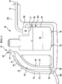
- FIG Figure 1 Another embodiment of a device 10 is shown in FIG Figure 1 shown schematically in the form of a steam cleaning device 82.
- the steam cleaning device 82 comprises a housing 100, on which a handle 60 with a passage is formed.
- the steam cleaning device 82 is designed in the form of a hand-held steam cleaning device 82. It can be connected via an electrical connection line 102 to a power network for supplying the steam cleaning device 82 with energy.
- a fluid reservoir 70 in the form of a steam boiler 104 is arranged in the housing 100. This comprises a heating device 78 for heating the fluid 98 contained in the steam boiler 104.
- the fluid 98 is water in this case.
- a valve device 18 is arranged on the steam boiler 104, the connection of which forms the fluid inlet 12.
- the connecting line 16 connects the valve device 18, which is designed in the form of a solenoid valve 106, to the fluid outlet 14 which is led out of the housing 100 and through which superheated steam can be dispensed.
- the first actuating member 22 is designed in the form of a first touch-sensitive actuating surface 64, specifically on the grip area 62 of the handle 60.
- a second touch-sensitive actuation surface 66 which defines the second actuation element 24, is formed adjacent to the first actuation surface 64 in the direction of an upper side of the steam cleaning device 82.
- the actuators 22 and 24 are designed in the form of capacitive contact sensors.
- the steam cleaning device 82 further comprises a display device 92 with a lighting element 94, which is arranged adjacent to the second actuating element 22 for displaying the operating states B and C, which correspond to the open position of the valve device 18.
- a user can grasp the handle 16 with one hand, in particular by moving his thumb, which initially touches the first actuation surface 64, onto the second actuation surface 66 to activate the dispensing of superheated steam by opening the fluid connection 16.
- the solenoid valve 106 is closed either by touching the second actuating surface 66 again or by switching off the steam cleaning device 82, for example, and releasing the handle 60.
- the first-mentioned variant corresponds to the procedure at time t 4 , as shown in Figure 3 the second alternative is shown at time t 8 .
- FIG Figure 2 Another exemplary embodiment of a steam cleaning device 82 is shown in FIG Figure 2 shown. It is designed in the form of a mobile steam cleaning device 82 with a housing 100, on which a plurality of rollers 108 are arranged.
- the steam boiler 104 is arranged in the housing 100.
- the steam cleaning device 82 can be connected to a power supply system with the connecting line 102, which is led into the housing 100.
- a hose 110 is led out of the housing 100, in which a connecting line 16 and at least one control line 112 are guided.
- the connecting line 16 connects with its first end, which defines the fluid inlet 12, the steam boiler 104 to the valve device 18 in the form of the solenoid valve 106, which is arranged in a handle 60 arranged at the end of the hose 110.
- a short connecting line 16 connects the solenoid valve 106 to the fluid outlet 14, which is led out of a handle housing 114 of the handle 60.
- the first actuating member 22 and the second actuating member 24 are arranged on the handle 60 in the form of first and second touch-sensitive actuating surfaces 64 and 66. In particular, these can be arranged within the handle housing 114, just as they are in the steam cleaning device 82 Figure 1 can be arranged within the housing 100.
- the actuation members 22 and 24 are designed in the form of capacitive contact sensors and are connected to the actuation detection device 26 for control purposes.
- the second actuating surface 66 is significantly larger than the first actuating surface 64. This is also the case with the steam cleaning device 82 Figure 1 so provided.
- the second actuating surface 66 adjoins the first actuating surface 64.
- a lighting element 94 of a display device 92 is arranged adjacent to the second actuating surface 66.
- the display device 92 signals the operating states B and C as schematically shown in FIG Figure 3 are shown and explained above.
- the display device 92 can also be designed to display one or more of the operating states A, D, E and F.
- the actuating device 20 described in connection with various exemplary embodiments of devices 10 can in particular also be used in other types of devices, for example in devices with mechanically operated cutting elements such as, in particular, chainsaws, hedge trimmers, lawn edge scissors, lawn trimmers or the like.
- first and second actuators can be provided in the manner described.
- a motor for driving the cutting elements can be activated or deactivated here.
- the device for shredding material to be cut, in particular for cutting grass or wood, which device is a drive which is connected to the at least one cutting element and an actuating device for activating the drive so that it assumes a working position, and for Deactivating the drive so that it assumes a rest position, the actuating device comprising at least one first actuating member and at least one second actuating member, the actuating device comprising an actuating detection device which is connected for control purposes to the at least one first actuating member and the at least one second actuating member and which is designed for detecting an actuation of the at least one first actuating member and the at least one second actuating member, and that the actuating device is designed for transferring n of the drive from the rest position into the working position only when the actuation detection device detects an actuation of the at least one second actuation element, while the actuation device detects an actuation of the at least one first actuation element.
- the principle of the continuous operation function that is to say without having to actuate two actuating elements at the same time, can thus also be easily implemented transferred to other devices.
- this function can only be implemented electronically. It can prevent activation of the respective device 10 in a purely electronic manner with comparable security as in mechanical security devices.
Landscapes
- Containers And Packaging Bodies Having A Special Means To Remove Contents (AREA)
- Infusion, Injection, And Reservoir Apparatuses (AREA)
Priority Applications (2)
| Application Number | Priority Date | Filing Date | Title |
|---|---|---|---|
| EP18177568.5A EP3581284B1 (fr) | 2018-06-13 | 2018-06-13 | Dispositif et procédé de distribution d'un fluide |
| PL18177568.5T PL3581284T3 (pl) | 2018-06-13 | 2018-06-13 | Urządzenie i sposób do podawania płynu |
Applications Claiming Priority (1)
| Application Number | Priority Date | Filing Date | Title |
|---|---|---|---|
| EP18177568.5A EP3581284B1 (fr) | 2018-06-13 | 2018-06-13 | Dispositif et procédé de distribution d'un fluide |
Publications (3)
| Publication Number | Publication Date |
|---|---|
| EP3581284A1 true EP3581284A1 (fr) | 2019-12-18 |
| EP3581284B1 EP3581284B1 (fr) | 2025-12-03 |
| EP3581284C0 EP3581284C0 (fr) | 2025-12-03 |
Family
ID=62715834
Family Applications (1)
| Application Number | Title | Priority Date | Filing Date |
|---|---|---|---|
| EP18177568.5A Active EP3581284B1 (fr) | 2018-06-13 | 2018-06-13 | Dispositif et procédé de distribution d'un fluide |
Country Status (2)
| Country | Link |
|---|---|
| EP (1) | EP3581284B1 (fr) |
| PL (1) | PL3581284T3 (fr) |
Cited By (1)
| Publication number | Priority date | Publication date | Assignee | Title |
|---|---|---|---|---|
| DE102023103284A1 (de) | 2023-02-10 | 2024-08-14 | Alfred Kärcher SE & Co. KG | Reinigungsgerät und Bedienvorrichtung zum Steuern eines Reinigungsgeräts |
Citations (3)
| Publication number | Priority date | Publication date | Assignee | Title |
|---|---|---|---|---|
| US3651391A (en) * | 1969-09-26 | 1972-03-21 | Black & Decker Mfg Co | Electronic switch arrangements |
| WO1996039255A1 (fr) * | 1995-06-05 | 1996-12-12 | C.H. Heist Corp. | Dispositif de securite destine a un systeme de projection d'un liquide a haute pression |
| WO2015197114A1 (fr) * | 2014-06-25 | 2015-12-30 | Alfred Kärcher Gmbh & Co. Kg | Appareil à vapeur portatif |
-
2018
- 2018-06-13 EP EP18177568.5A patent/EP3581284B1/fr active Active
- 2018-06-13 PL PL18177568.5T patent/PL3581284T3/pl unknown
Patent Citations (3)
| Publication number | Priority date | Publication date | Assignee | Title |
|---|---|---|---|---|
| US3651391A (en) * | 1969-09-26 | 1972-03-21 | Black & Decker Mfg Co | Electronic switch arrangements |
| WO1996039255A1 (fr) * | 1995-06-05 | 1996-12-12 | C.H. Heist Corp. | Dispositif de securite destine a un systeme de projection d'un liquide a haute pression |
| WO2015197114A1 (fr) * | 2014-06-25 | 2015-12-30 | Alfred Kärcher Gmbh & Co. Kg | Appareil à vapeur portatif |
Cited By (2)
| Publication number | Priority date | Publication date | Assignee | Title |
|---|---|---|---|---|
| DE102023103284A1 (de) | 2023-02-10 | 2024-08-14 | Alfred Kärcher SE & Co. KG | Reinigungsgerät und Bedienvorrichtung zum Steuern eines Reinigungsgeräts |
| WO2024165695A1 (fr) | 2023-02-10 | 2024-08-15 | Alfred Kärcher SE & Co. KG | Appareil de nettoyage et dispositif de commande pour commander un appareil de nettoyage |
Also Published As
| Publication number | Publication date |
|---|---|
| EP3581284B1 (fr) | 2025-12-03 |
| EP3581284C0 (fr) | 2025-12-03 |
| PL3581284T3 (pl) | 2026-03-23 |
Similar Documents
| Publication | Publication Date | Title |
|---|---|---|
| DE3311382C2 (de) | Verfahren zum Steuern eines Hochdruckreinigungsgerätes und Hochdruckreinigungsgerät zur Durchführung dieses Verfahrens | |
| DE60225326T2 (de) | Fluidkontrollsystem für die angiographie | |
| EP3031315B1 (fr) | Dispositif de poignée pour outils de jardinage | |
| DE1555692A1 (de) | Reinigungsvorrichtung,insbesondere zum Reinigen von Fahrzeugen und/oder Flugzeugen | |
| DE102009049430A1 (de) | Ophthalmochirurgische Messvorrichtung | |
| DE102008026014B4 (de) | Chirurgisches System | |
| DE2808098A1 (de) | Automatische spritzeinrichtung | |
| DE202013005807U1 (de) | Türklinke | |
| WO2014140134A1 (fr) | Robinet de cuisine et procédé de commande | |
| EP1119420B1 (fr) | Dispositif de peinture | |
| EP3581284B1 (fr) | Dispositif et procédé de distribution d'un fluide | |
| DE102017211515B4 (de) | Verfahren zur Desinfizierung wenigstens einer Handfläche in einem Kraftfahrzeug und Vorrichtung zur Durchführung des Verfahrens | |
| DE2419105C2 (de) | Vorrichtung zum Texturieren von Garn | |
| WO1996006691A1 (fr) | Dispositif et procede de nettoyage de couverts | |
| EP2516723B1 (fr) | Centrale vapeur équipée d'un générateur de vapeur | |
| DE60107190T2 (de) | Vorrichtung zum Reinigen und Sprühen | |
| EP2397063A1 (fr) | Fer à repasser doté d'un système de détartrage et de nettoyage automatique | |
| DE102016200419A1 (de) | Hydraulischer Aktuator für ein Heißgetränke-Zubereitungsgerät | |
| EP2207490B1 (fr) | Appareil chirurgical à jet d'eau et procédé pour son utilisation | |
| EP0687762B1 (fr) | Pistolet-détacheur | |
| DE3821446C2 (de) | Einrichtung zum Zerstäuben von Produkten für Straßenbeläge | |
| DE2011198A1 (de) | Leitungsrückholsy stern | |
| WO2023001574A1 (fr) | Robinetterie sanitaire pour la distribution d'eau chaude et procédé d'initiation de la distribution d'eau chaude dans une robinetterie sanitaire | |
| DE2551994C3 (de) | BehälterfUUvorrichtung | |
| DE4232297C1 (de) | Fahrzeug-Waschvorrichtung |
Legal Events
| Date | Code | Title | Description |
|---|---|---|---|
| PUAI | Public reference made under article 153(3) epc to a published international application that has entered the european phase |
Free format text: ORIGINAL CODE: 0009012 |
|
| STAA | Information on the status of an ep patent application or granted ep patent |
Free format text: STATUS: THE APPLICATION HAS BEEN PUBLISHED |
|
| AK | Designated contracting states |
Kind code of ref document: A1 Designated state(s): AL AT BE BG CH CY CZ DE DK EE ES FI FR GB GR HR HU IE IS IT LI LT LU LV MC MK MT NL NO PL PT RO RS SE SI SK SM TR |
|
| AX | Request for extension of the european patent |
Extension state: BA ME |
|
| STAA | Information on the status of an ep patent application or granted ep patent |
Free format text: STATUS: REQUEST FOR EXAMINATION WAS MADE |
|
| 17P | Request for examination filed |
Effective date: 20200616 |
|
| RBV | Designated contracting states (corrected) |
Designated state(s): AL AT BE BG CH CY CZ DE DK EE ES FI FR GB GR HR HU IE IS IT LI LT LU LV MC MK MT NL NO PL PT RO RS SE SI SK SM TR |
|
| STAA | Information on the status of an ep patent application or granted ep patent |
Free format text: STATUS: EXAMINATION IS IN PROGRESS |
|
| 17Q | First examination report despatched |
Effective date: 20220218 |
|
| P01 | Opt-out of the competence of the unified patent court (upc) registered |
Effective date: 20230520 |
|
| GRAP | Despatch of communication of intention to grant a patent |
Free format text: ORIGINAL CODE: EPIDOSNIGR1 |
|
| STAA | Information on the status of an ep patent application or granted ep patent |
Free format text: STATUS: GRANT OF PATENT IS INTENDED |
|
| GRAJ | Information related to disapproval of communication of intention to grant by the applicant or resumption of examination proceedings by the epo deleted |
Free format text: ORIGINAL CODE: EPIDOSDIGR1 |
|
| STAA | Information on the status of an ep patent application or granted ep patent |
Free format text: STATUS: EXAMINATION IS IN PROGRESS |
|
| INTG | Intention to grant announced |
Effective date: 20240220 |
|
| GRAP | Despatch of communication of intention to grant a patent |
Free format text: ORIGINAL CODE: EPIDOSNIGR1 |
|
| STAA | Information on the status of an ep patent application or granted ep patent |
Free format text: STATUS: GRANT OF PATENT IS INTENDED |
|
| INTC | Intention to grant announced (deleted) | ||
| INTG | Intention to grant announced |
Effective date: 20240326 |
|
| GRAJ | Information related to disapproval of communication of intention to grant by the applicant or resumption of examination proceedings by the epo deleted |
Free format text: ORIGINAL CODE: EPIDOSDIGR1 |
|
| STAA | Information on the status of an ep patent application or granted ep patent |
Free format text: STATUS: EXAMINATION IS IN PROGRESS |
|
| GRAP | Despatch of communication of intention to grant a patent |
Free format text: ORIGINAL CODE: EPIDOSNIGR1 |
|
| INTC | Intention to grant announced (deleted) | ||
| STAA | Information on the status of an ep patent application or granted ep patent |
Free format text: STATUS: GRANT OF PATENT IS INTENDED |
|
| INTG | Intention to grant announced |
Effective date: 20240905 |
|
| GRAJ | Information related to disapproval of communication of intention to grant by the applicant or resumption of examination proceedings by the epo deleted |
Free format text: ORIGINAL CODE: EPIDOSDIGR1 |
|
| STAA | Information on the status of an ep patent application or granted ep patent |
Free format text: STATUS: EXAMINATION IS IN PROGRESS |
|
| GRAP | Despatch of communication of intention to grant a patent |
Free format text: ORIGINAL CODE: EPIDOSNIGR1 |
|
| STAA | Information on the status of an ep patent application or granted ep patent |
Free format text: STATUS: GRANT OF PATENT IS INTENDED |
|
| INTC | Intention to grant announced (deleted) | ||
| INTG | Intention to grant announced |
Effective date: 20250121 |
|
| GRAJ | Information related to disapproval of communication of intention to grant by the applicant or resumption of examination proceedings by the epo deleted |
Free format text: ORIGINAL CODE: EPIDOSDIGR1 |
|
| STAA | Information on the status of an ep patent application or granted ep patent |
Free format text: STATUS: EXAMINATION IS IN PROGRESS |
|
| GRAP | Despatch of communication of intention to grant a patent |
Free format text: ORIGINAL CODE: EPIDOSNIGR1 |
|
| STAA | Information on the status of an ep patent application or granted ep patent |
Free format text: STATUS: GRANT OF PATENT IS INTENDED |
|
| INTC | Intention to grant announced (deleted) | ||
| INTG | Intention to grant announced |
Effective date: 20250624 |
|
| GRAS | Grant fee paid |
Free format text: ORIGINAL CODE: EPIDOSNIGR3 |
|
| GRAA | (expected) grant |
Free format text: ORIGINAL CODE: 0009210 |
|
| STAA | Information on the status of an ep patent application or granted ep patent |
Free format text: STATUS: THE PATENT HAS BEEN GRANTED |
|
| AK | Designated contracting states |
Kind code of ref document: B1 Designated state(s): AL AT BE BG CH CY CZ DE DK EE ES FI FR GB GR HR HU IE IS IT LI LT LU LV MC MK MT NL NO PL PT RO RS SE SI SK SM TR |
|
| REG | Reference to a national code |
Ref country code: CH Ref legal event code: F10 Free format text: ST27 STATUS EVENT CODE: U-0-0-F10-F00 (AS PROVIDED BY THE NATIONAL OFFICE) Effective date: 20251203 Ref country code: GB Ref legal event code: FG4D Free format text: NOT ENGLISH |
|
| REG | Reference to a national code |
Ref country code: DE Ref legal event code: R096 Ref document number: 502018016243 Country of ref document: DE |
|
| REG | Reference to a national code |
Ref country code: IE Ref legal event code: FG4D Free format text: LANGUAGE OF EP DOCUMENT: GERMAN |
|
| U01 | Request for unitary effect filed |
Effective date: 20260105 |
|
| U07 | Unitary effect registered |
Designated state(s): AT BE BG DE DK EE FI FR IT LT LU LV MT NL PT RO SE SI Effective date: 20260112 |
|
| P04 | Withdrawal of opt-out of the competence of the unified patent court (upc) registered |
Free format text: CASE NUMBER: UPC_APP_227109_1/2023 Effective date: 20260112 |
|
| PG25 | Lapsed in a contracting state [announced via postgrant information from national office to epo] |
Ref country code: ES Free format text: LAPSE BECAUSE OF FAILURE TO SUBMIT A TRANSLATION OF THE DESCRIPTION OR TO PAY THE FEE WITHIN THE PRESCRIBED TIME-LIMIT Effective date: 20251203 |
|
| PG25 | Lapsed in a contracting state [announced via postgrant information from national office to epo] |
Ref country code: NO Free format text: LAPSE BECAUSE OF FAILURE TO SUBMIT A TRANSLATION OF THE DESCRIPTION OR TO PAY THE FEE WITHIN THE PRESCRIBED TIME-LIMIT Effective date: 20260303 |
|
| PG25 | Lapsed in a contracting state [announced via postgrant information from national office to epo] |
Ref country code: HR Free format text: LAPSE BECAUSE OF FAILURE TO SUBMIT A TRANSLATION OF THE DESCRIPTION OR TO PAY THE FEE WITHIN THE PRESCRIBED TIME-LIMIT Effective date: 20251203 |
|
| PG25 | Lapsed in a contracting state [announced via postgrant information from national office to epo] |
Ref country code: RS Free format text: LAPSE BECAUSE OF FAILURE TO SUBMIT A TRANSLATION OF THE DESCRIPTION OR TO PAY THE FEE WITHIN THE PRESCRIBED TIME-LIMIT Effective date: 20260303 |