EP3581341A1 - Procédé destiné au fonctionnement d'un robot, support de données pourvu d'un code de programme correspondant, robot et système de robot - Google Patents
Procédé destiné au fonctionnement d'un robot, support de données pourvu d'un code de programme correspondant, robot et système de robot Download PDFInfo
- Publication number
- EP3581341A1 EP3581341A1 EP18177548.7A EP18177548A EP3581341A1 EP 3581341 A1 EP3581341 A1 EP 3581341A1 EP 18177548 A EP18177548 A EP 18177548A EP 3581341 A1 EP3581341 A1 EP 3581341A1
- Authority
- EP
- European Patent Office
- Prior art keywords
- robot
- coordinate system
- tool
- axis
- target
- Prior art date
- Legal status (The legal status is an assumption and is not a legal conclusion. Google has not performed a legal analysis and makes no representation as to the accuracy of the status listed.)
- Granted
Links
Images

Classifications
-
- B—PERFORMING OPERATIONS; TRANSPORTING
- B25—HAND TOOLS; PORTABLE POWER-DRIVEN TOOLS; MANIPULATORS
- B25J—MANIPULATORS; CHAMBERS PROVIDED WITH MANIPULATION DEVICES
- B25J9/00—Program-controlled manipulators
- B25J9/16—Program controls
- B25J9/1628—Program controls characterised by the control loop
- B25J9/1643—Program controls characterised by the control loop redundant control
-
- B—PERFORMING OPERATIONS; TRANSPORTING
- B25—HAND TOOLS; PORTABLE POWER-DRIVEN TOOLS; MANIPULATORS
- B25J—MANIPULATORS; CHAMBERS PROVIDED WITH MANIPULATION DEVICES
- B25J9/00—Program-controlled manipulators
- B25J9/16—Program controls
- B25J9/1656—Program controls characterised by programming, planning systems for manipulators
- B25J9/1664—Program controls characterised by programming, planning systems for manipulators characterised by motion, path, trajectory planning
-
- B—PERFORMING OPERATIONS; TRANSPORTING
- B25—HAND TOOLS; PORTABLE POWER-DRIVEN TOOLS; MANIPULATORS
- B25J—MANIPULATORS; CHAMBERS PROVIDED WITH MANIPULATION DEVICES
- B25J19/00—Accessories fitted to manipulators, e.g. for monitoring, for viewing; Safety devices combined with or specially adapted for use in connection with manipulators
-
- B—PERFORMING OPERATIONS; TRANSPORTING
- B25—HAND TOOLS; PORTABLE POWER-DRIVEN TOOLS; MANIPULATORS
- B25J—MANIPULATORS; CHAMBERS PROVIDED WITH MANIPULATION DEVICES
- B25J9/00—Program-controlled manipulators
- B25J9/16—Program controls
- B25J9/1602—Program controls characterised by the control system, structure, architecture
-
- B—PERFORMING OPERATIONS; TRANSPORTING
- B25—HAND TOOLS; PORTABLE POWER-DRIVEN TOOLS; MANIPULATORS
- B25J—MANIPULATORS; CHAMBERS PROVIDED WITH MANIPULATION DEVICES
- B25J9/00—Program-controlled manipulators
- B25J9/16—Program controls
- B25J9/1602—Program controls characterised by the control system, structure, architecture
- B25J9/1607—Calculation of inertia, jacobian matrixes and inverses
-
- B—PERFORMING OPERATIONS; TRANSPORTING
- B25—HAND TOOLS; PORTABLE POWER-DRIVEN TOOLS; MANIPULATORS
- B25J—MANIPULATORS; CHAMBERS PROVIDED WITH MANIPULATION DEVICES
- B25J9/00—Program-controlled manipulators
- B25J9/16—Program controls
- B25J9/1656—Program controls characterised by programming, planning systems for manipulators
- B25J9/1669—Program controls characterised by programming, planning systems for manipulators characterised by special application, e.g. multi-arm co-operation, assembly, grasping
-
- G—PHYSICS
- G05—CONTROLLING; REGULATING
- G05B—CONTROL OR REGULATING SYSTEMS IN GENERAL; FUNCTIONAL ELEMENTS OF SUCH SYSTEMS; MONITORING OR TESTING ARRANGEMENTS FOR SUCH SYSTEMS OR ELEMENTS
- G05B2219/00—Program-control systems
- G05B2219/30—Nc systems
- G05B2219/39—Robotics, robotics to robotics hand
- G05B2219/39081—Inexact solution for orientation or other DOF with relation to type of task
-
- G—PHYSICS
- G05—CONTROLLING; REGULATING
- G05B—CONTROL OR REGULATING SYSTEMS IN GENERAL; FUNCTIONAL ELEMENTS OF SUCH SYSTEMS; MONITORING OR TESTING ARRANGEMENTS FOR SUCH SYSTEMS OR ELEMENTS
- G05B2219/00—Program-control systems
- G05B2219/30—Nc systems
- G05B2219/40—Robotics, robotics mapping to robotics vision
- G05B2219/40338—Task priority redundancy
Definitions
- the invention relates to a method for operating a robot, a data memory with a corresponding program code, a corresponding robot and a corresponding robot system.
- robots with movable robot arms are becoming increasingly widespread today.
- These robots can, for example, position components or tools in space at a predefined location and in a predefined orientation or alignment, that is to say in a predefined pose.
- This is generally a 6D problem, i.e. a problem with or in six dimensions.
- These are three point or spatial coordinates for the position and three angles for the orientation. If the respective component or tool is moved between two different poses, rotations or rotational movements of the robot and the tool are usually associated with this.
- a marker arranged on the component or tool or on the robot which can be used in a manner known per se for tracking the component or tool or the robot, from a detection area of a corresponding detection device -
- a camera - is moved or covered, for example, by the robot.
- the object of the present invention is to enable a tool or component to be positioned by a robot with improved availability.
- a method according to the invention serves to operate a robot for positioning a tool, in particular functionally rotationally symmetrical about a predetermined axis, in a target pose.
- the robot has a robot base and a movable robot arm adjoining it, at the distal end of which - that is, a robot flange that is facing away or distant - a robot flange is arranged, on which the tool is held directly or indirectly, that is, at least indirectly.
- the robot base is fixed or rigidly positioned, for example in relation to a fixed spatial coordinate system of a room in which the robot is located and / or in relation to a workpiece or target object.
- the robot in particular the tool, is thus positioned relative to this workpiece or target object, for example in order to interact with it or to enable interaction with it in a predetermined manner.
- the robot arm can be moved relative to the robot foot and thus in particular also relative to the target object.
- the robot arm can preferably have at least six degrees of freedom, for example realized by corresponding joints and / or axes of rotation.
- the robot can thus be, for example, a conventional industrial robot or a medical robot, in particular a lightweight robot.
- the term tool is to be interpreted very broadly here and can in principle include any objects held or guided by the robot, for example also a workpiece or semi-finished product or the like.
- the target object can be in a preferred Use case, for example, a patient.
- the tool can then be, for example, a guide sleeve for a needle, an injector or the like (NGS, English: "Needle-Guide Sheath").
- NGS needle-Guide Sheath
- the target pose of this guide sleeve can then be predetermined such that the needle or injector can be guided through the guide sleeve arranged in the target pose and can then reach a predetermined target point on the patient in or from a predetermined direction of movement.
- the method according to the invention can therefore be used particularly advantageously for positioning a tool which is rotationally symmetrical and / or whose function, application or use does not depend on or be influenced or impaired by a rotation or rotational position with respect to at least one axis during the positioning.
- the corresponding axis can thus be an axis of symmetry in geometric and / or functional terms.
- the term “axis of symmetry” which may be used in the following is therefore not to be understood purely geometrically.
- the tool may also be possible for the tool to be rotatable or rotatable about the corresponding axis by the robot, in particular on the robot flange.
- the tool can then, for example, be moved manually into a desired rotational or rotary position by a user after the tool has been positioned in the predetermined target pose.
- the corresponding axis of the tool is specified, about which rotations are insignificant as described.
- a Cartesian reference coordinate system ⁇ 0 ⁇ originating on or in the robot base is specified.
- the reference coordinate system ⁇ 0 ⁇ thus has three coordinate axes, each of which is perpendicular to one another in pairs, which are referred to below as x 0 , y 0 and z 0 , and has a predetermined and fixed or constant spatial positional relationship to the robot base.
- a Cartesian target coordinate system ⁇ r ⁇ originating at a point of the tool, preferably at a tip of the tool, a z-axis corresponding to the specified axis of the tool and an x-axis and y-axis each with initially undetermined orientations is specified.
- 3D spatial coordinates 0 t r of the point of the tool and an orientation of the specified axis, each expressed in the reference coordinate system ⁇ 0 ⁇ , are specified as part of the target pose for the tool.
- the orientations of the x-axis and the y-axis of the target coordinate system ⁇ r ⁇ expressed in the reference coordinate system ⁇ 0 ⁇ are then calculated.
- a first cross product and a second cross product are calculated.
- the first cross product is calculated from the predefined orientation of the predefined axis, that is to say the orientation or direction of the z axis of the target coordinate system ⁇ r ⁇ , and a direction vector of a coordinate axis of the reference coordinate system which is not parallel or is not collinear with this ⁇ 0 ⁇ .
- the second cross product is calculated from a result of the first cross product and the given orientation of the given axis, ie the z-axis of the target coordinate system ⁇ r ⁇ , expressed in the reference coordinate system ⁇ 0 ⁇ .
- a 4x4 matrix is then generated, which defines a pose 0 H r of the target coordinate system ⁇ r ⁇ in relation to the reference coordinate system ⁇ 0 ⁇ , from the orientations of the coordinate axes of the target coordinate system ⁇ r ⁇ expressed in the reference coordinate system ⁇ 0 ⁇ and from the same in the reference coordinate system ⁇ 0 ⁇ expressed 3D spatial coordinates of the point of the tool and from an additional 1x4 line vector.
- the additional 1x4 line vector can have the shape (0, 0, 0, 1) and serves to fill up the matrix so that it has a square shape.
- the mathematical object 0 H r can be the 4x4 matrix itself. This matrix is also referred to as the corresponding homogeneous matrix or as a complete homogeneous matrix.
- the various specifications can be made, for example, by calling up corresponding data from a data memory provided and / or by manual inputs, for example via a graphical user interface.
- a pose means a combination of a spatial location and an orientation or direction, as is customary in the technical field of robotics.
- the orientation can be specified or defined by a corresponding vector, for example a unit or direction vector.
- a R B denotes an orientation or rotation of the coordinate system ⁇ B ⁇ with respect to or expressed in a coordinate system ⁇ A ⁇ , where R can be a rotation matrix.
- R can be a rotation matrix.
- the coordinate axes of the coordinate system ⁇ B ⁇ expressed in the coordinate system A are therefore written according to this notation as A x B , A y B , A z B.
- a method is proposed to determine or calculate an orientation or alignment of the target coordinate system ⁇ r ⁇ with respect to the stationary reference coordinate system ⁇ 0 ⁇ . Since the z-axis of the target coordinate system ⁇ r ⁇ is predetermined by the given axis or axis of symmetry of the tool, a central contribution of the present invention to the technical field of robot control is to determine the x and y axes of the target coordinate system ⁇ r ⁇ or in determining their orientation or alignment.
- a special property and a clear advantage of the present invention is that when the method according to the invention is used, the tool rotates minimally when the robot is operating. The present invention thus ultimately avoids unnecessary rotary movements of the tool.
- a marker in the sense of the present invention is an object which is designed such that its orientation in space can be clearly determined from any perspective.
- the marker can be, for example, an optical or electromagnetic marker be, which can be detected accordingly, for example with a camera or a corresponding sensor.
- visible light, infrared light, radio frequencies, X-rays or the like can be used.
- x 0 and y 0 indicate the x and y axes of the reference coordinate system ⁇ 0 ⁇ and 0 x r , 0 y r , 0 z r the coordinate axes of the target coordinate system ⁇ r ⁇ expressed in vector form in the reference coordinate system ⁇ 0 ⁇ .
- the y-axis y 0 of the reference coordinate system can be used as a base or reference can be used to calculate the orientations of the x and y axes of the target coordinate system.
- An angle between 0 z r and x 0 can be derived because of the orientation or orientation of the reference coordinate system ⁇ 0 ⁇ is known and known. In this way, a rotation-minimal movement of the tool into the target pose, which is particularly reliable with regard to traceability and visibility, can advantageously be achieved in any case. This can thus be achieved particularly advantageously regardless of the orientation of the predetermined axis of the tool with the same particularly low computing effort.
- a pose or homogeneous matrix r H f of the robot flange corresponding to the pose 0 H r or to the corresponding homogeneous matrix of the target coordinate system ⁇ r ⁇ and expressed in this pose or homogeneous matrix r H f of the robot flange is determined, which has a spatial positional relationship between the point of the tool, for example the tip of the tool, and the robot flange.
- the index f stands for the robot flange or a Cartesian coordinate system of the robot flange, which therefore has its origin in or on the robot flange and in which the pose of the robot flange can be described directly.
- the calibration can be carried out, for example, once before the method steps described above and / or for example each time the robot is started or started up and / or for example when the tool is changed.
- the tool can be exchangeable so that different tools can be held or guided by the same robot.
- the robot flange is an integral part of the robot. If the robot flange is in the pose r H f , this ensures that the tool is in the specified target pose.
- the conversion of the target pose of the tool into the corresponding pose r H f of the robot flange is particularly advantageous since it can then be used as a direct input or target variable for a model-based control or kinematics of the robot that is typically present anyway, regardless of which tool is used becomes or in which spatial positional relationship to the robot flange the tool is mounted.
- the method according to the invention can thus be applied with minimal modifications to existing robots or robot controls.
- a, in particular optical, marker is arranged in a predetermined positional relationship to the point of the tool on the robot or on the robot for the calibration.
- the optical marker is then detected by means of a detection device, which is arranged in a predetermined positional relationship to the robot base, in an auxiliary coordinate system ⁇ e ⁇ originating at the point of the tool and initially undetermined orientation relative to the target coordinate system ⁇ r ⁇ .
- a spatial positional relationship, ie orientation, of the auxiliary coordinate system relative to the robot flange is then determined from corresponding detection data of the marker.
- the pose r H f of the robot flange is then determined from the orientations of the axes of the target coordinate system ⁇ r ⁇ expressed in the reference coordinate system ⁇ 0 ⁇ and a predetermined forward kinematics of the robot using the identical origin of the target coordinate system ⁇ r ⁇ and the auxiliary coordinate system ⁇ e ⁇ .
- the marker can therefore initially be arranged in any spatial relationship and orientation.
- the auxiliary coordinate system ⁇ e ⁇ can preferably be predetermined or fixed by the respective orientation of the marker, that is to say in dependence on the respective orientation of the marker. A particularly simple and flexible implementation of the calibration is thus advantageously made possible.
- H indicates the corresponding homogeneous 4x4 matrix.
- a control signal for the robot is automatically generated from the determined quantities and a predetermined kinematics model of the robot, by means of which the robot is moved from its current pose in such a way that the tool reaches the target pose specified for this or is transferred.
- the present invention is not only used for example for theoretical or model-based applications, but for the actual operation of the robot. The advantages described, which result from the use of the method according to the invention in the control of the robot, can thus be realized in practice.
- a predefined kinematic model of the robot is used to automatically check whether the target pose predefined for the tool can be reached by the robot.
- restrictions due to mechanical restrictions in an environment of the robot, limitations in a range of motion of joints of the robot arm, singularities in the kinematics model and / or the like can occur, which can prevent the robot from reaching the predetermined target pose.
- the target coordinate system ⁇ r ⁇ i.e. its specific orientation, will alternate in a positive and negative direction around it until a reachable target pose is found by predetermined, incrementally increasing angular amounts z-axis rotates.
- the angle for the rotations is thus set - in particular increased - with regard to its amount and its direction - according to a predetermined sequence.
- the check as to whether the resulting target pose can be reached is carried out again.
- the new corresponding pose 0 H f for the robot flange can also be determined.
- a small angle for example an angle or angular amount of at most 15 °, preferably of for example 5 °, can preferably be specified as the angle increment, that is to say be used.
- the target coordinate system ⁇ r ⁇ can be rotated by 5 ° in the positive direction. If the resulting target pose cannot be reached either, the target coordinate system ⁇ r ⁇ can be rotated in the negative direction.
- the angular amount for the rotation in the negative direction can be increased by an angular increment to 10 °, for example.
- the target coordinate system ⁇ r ⁇ is then rotated by 5 ° in the negative direction after this rotation in relation to the original orientation before the rotation in the positive direction. If the resulting target pose cannot be reached either, the target coordinate system ⁇ r ⁇ can be rotated from this new position in the opposite direction, i.e. in the positive direction, for example by 15 °, etc.
- This procedure can advantageously automatically and particularly reliably find a target pose which, with a particularly high degree of probability, will continue to enable visibility or traceability or restrict it as little as possible.
- the tool is rotationally symmetrical with respect to the z-axis of the target coordinate system ⁇ r ⁇ and / or rotations of the tool about this axis are irrelevant, i.e. can be neglected for the control or operation of the robot and / or are not subject to any restrictions, the rotation of the target coordinate system advantageously has no practical effect on the tool ultimately assumed target pose. Rotating the target coordinate system ⁇ r ⁇ around its z-axis is therefore only relevant for the movement of the robot arm to set or approach the target pose for the tool or the robot flange. This expresses that, as explained, the original positioning problem is effectively a 5D problem.
- Another aspect of the present invention is a data memory with a program code that codes or represents the method steps of at least one embodiment of the method according to the invention.
- the program code is thus a computer program product which can be executed by a processor device, which in turn results in the automatic execution or execution of the corresponding method according to the invention.
- the program code can be written in different programming languages. Depending on the specific requirements, C, C ++, Java, Python, Scriptia, MATLAB, Fortran or others can be used.
- Another aspect of the present invention is a robot with a control device for controlling the robot.
- This control unit comprises a data memory according to the invention and a processor device connected to it for executing the program code stored or stored in the data memory.
- the control device or the robot has an interface for receiving specifications.
- the reference coordinate system ⁇ 0 ⁇ , the target coordinate system ⁇ r ⁇ and / or the target pose for the tool can be specified via this interface.
- the interface can therefore be a data interface, which can be connected to a further electronic device, for example a further data memory, a further control device and / or a user interface.
- the robot according to the invention can thus be set up to carry out or execute the method according to the invention and accordingly the robot according to the invention can in particular be the robot mentioned in connection with the method according to the invention. Accordingly, the robot according to the invention can also have the properties and / or components or devices mentioned in connection with the method according to the invention.
- Another aspect of the present invention is a robot system which comprises a robot according to the invention and a detection device coupled to it and arranged in a predetermined positional relationship with this robot for detecting at least one marker arranged on the robot.
- the robot system according to the invention is set up to automatically determine an orientation of the marker, that is to say its spatial arrangement and position, from the detection data of the marker provided by the detection device.
- the robot system is set up to use this specific orientation of the marker for or during operation of the robot, for example for the calibration explained in connection with the method according to the invention.
- the robot system according to the invention is thus set up to execute or carry out at least one embodiment of the method according to the invention.
- the detection device and the marker of the robot system according to the invention can in particular be the detection device or camera mentioned in connection with the method according to the invention or the, in particular optical, marker mentioned in connection with the method according to the invention.
- the described components of the embodiments each represent individual features of the invention that are to be considered independently of one another, which further develop the invention independently of one another and are therefore also to be regarded individually or in a combination other than the one shown as part of the invention. Furthermore, the described embodiments can also be supplemented by further features of the invention that have already been described.
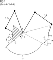
- FIG. 1 shows a schematic representation to illustrate a robotic positioning method according to the prior art.
- a conventional robot 1 is shown here in a start pose 2 and an end pose 3.
- a tool 4 is held at one end of the conventional robot 1.
- a base coordinate system 5 with an x-axis x 0 and two further coordinate axes arranged perpendicular to it is shown here.
- a further coordinate system with an x-axis x r and a second axis 6 arranged perpendicular to it is arranged at a tip of the tool 4.
- a third axis of this further coordinate system runs along a predefined axis of the tool, which here is in particular a main axis of extension or symmetry of the tool 4.
- a plane 7 is spanned so that both the axis of symmetry of the tool 4 and an origin or point of origin of the base coordinate system 5 lie or are contained in this plane 7.
- the x-axis x 0 or the second axis 6 can then be defined such that they extend perpendicular to the plane 7.
- a rotation 8 indicated here by an arrow is provided, among other things.
- the axis of symmetry of the tool 4 in the example shown here has the same orientation, for example in relation to the base coordinate system 5 and / or in relation to an external camera which is arranged in a fixed manner with respect to the base coordinate system 5. It can be clearly seen that the orientations of the x-axis x r and the second axis 6 in the end pose 3 are fundamentally different from the corresponding orientations of the x-axis x r and the second axis 6 in the starting pose 2.
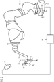
- FIG 2 shows a schematic perspective illustration of a robot system with a robot 10.
- the robot 10 comprises a static, that is to say stationary robot base 11.
- the robot base 11 is stationary with respect to a surrounding space in which the robot 10 is arranged.
- the robot 10 further comprises a movable robot arm 12, which extends from the robot base 11.
- a robot flange 13 of the robot 10 is arranged at a distal end of the robot arm 12, that is, facing away from the robot base 11.
- a connection element is in turn present on this robot flange 13 14 arranged for holding the tool 4.
- the tool 4 is rotationally symmetrical about a predetermined axis of rotation or symmetry 15, which is indicated schematically here.
- rotationally symmetrical tool 4 instead of the rotationally symmetrical tool 4, other tools or objects can be used in the same way, which also need not be rotationally symmetrical. A certain corresponding axis can then simply be specified or defined. Rotations around this axis will then be considered irrelevant or treated.
- an optical marker 16 is arranged on the tool 4 in the present case.
- This marker 16 is designed in a manner known per se so that its orientation or pose can be clearly determined from any external point of view, that is to say viewed from any perspective.
- a camera 17 is provided for detecting the marker 16 or its orientation or pose - in other words, ultimately for tracking the marker 16 and thus the tool 4.
- the orientation of the marker 16 can thus always be determined from corresponding image data of the marker 16 recorded by the camera 17 and the tool 4 or the robot 10 can thus be tracked.
- the marker 16 is arranged in particular in a predefined spatial relationship to the tool 4, in particular to the tip thereof.
- a control unit 18, which is connected to the robot 10 and to the camera 17, for controlling the robot 10.
- the robot 10, the control device 18 and the camera 17 can together form a robot system or be part of the robot system.
- the control device 18 can also be part of the robot 10 and then integrated into it, for example.
- FIG 3 shows a schematic exemplary flow chart 18 for a method for operating the robot system for positioning the tool 4 in the end pose 3 or in a predetermined target pose. This procedure will now be described with reference to FIG 2 explained.
- the method is started in a method step S1.
- the robot system can be activated.
- a kinematics model of the robot 10 that is to say, for example, a model-based forward kinematics of the robot 10, can be specified or provided here.
- a Cartesian of the reference coordinate system ⁇ 0 ⁇ and a Cartesian target coordinate system ⁇ r ⁇ are specified or defined.
- the reference coordinate system ⁇ 0 ⁇ is arranged stationary on the robot base 11. Both an origin of the reference coordinate system ⁇ 0 ⁇ and its coordinate axes x 0 , y 0 , z 0 or their orientations, in other words a pose of the reference coordinate system ⁇ 0 ⁇ , remain during the operation of the robot 10, in particular when the robot arm 12 is moving unchanged.
- An origin of the target coordinate system ⁇ r ⁇ is arranged at the tip of the tool 4.
- a z-axis z r of the target coordinate system ⁇ r ⁇ coincides with the predetermined axis of symmetry 15 of the tool 4.
- the aim here is to ultimately determine or calculate a 6D or 6-DoF pose (DoF: "Degrees of Freedom") of the robot flange 13 in such a way that when it is reached the tip of the tool 4 has a predetermined 3D target position occupies in space and also extends the axis of symmetry 15 in a predetermined direction or orientation.
- the tool 4 is a guide sleeve (NGS) for a needle. If the robot flange 13 and thus the tool 4 are in the respective target pose, the corresponding needle can then be guided through the guide sleeve, that is to say through the tool 4, in order, for example, from the predetermined direction to a specific predetermined location of a target object (not shown here) of a patient.
- An exact positioning of the tool 4 can be done in a medical Context can be particularly important, for example, in order to be able to carry out injury-free treatment of the patient. In other areas of application, however, exact positioning is of course important and desirable.
- exact positioning is of course important and desirable.
- the needle guided by the tool 4 can reach the predetermined target position from the predetermined direction regardless of the angle by which the tool 4 is rotated about the axis of symmetry 15.
- the tool 4 has at least one rotationally symmetrical interior, through which the respective needle can be guided in the same way regardless of its rotational position about the axis of symmetry 15.
- the rotation of the tool 4 about the axis of symmetry 15 or a corresponding angle is thus free, that is to say can be selected or set as desired when the robot flange 13 is positioned.
- the problem of positioning tool 4 in the specified target pose is thus effectively a 5D problem.
- a pose of the target coordinate system ⁇ r ⁇ to be reached or given in the target pose of the tool 4 is initially only determined to the extent that the origin of the target coordinate system ⁇ r ⁇ is arranged at the tip of the tool 4 and the z-axis z r of the target coordinate system ⁇ r ⁇ corresponds to the axis of symmetry 15 of the tool 4 or coincides therewith.
- any Cartesian coordinate systems used including the target coordinate system ⁇ r ⁇ , can be expressed in or in relation to the reference coordinate system ⁇ 0 ⁇ .
- the target pose for the tool 4 is then specified as the z-axis 0 z r of the target coordinate system ⁇ r ⁇ expressed in the reference coordinate system ⁇ 0 ⁇ and as 3D space or point coordinates 0 t r of the target point of the tip of the tool 4 - corresponding to the origin of the target coordinate system ⁇ r ⁇ - also expressed in the reference coordinate system ⁇ 0 ⁇ .
- a calibration is carried out in order to determine a spatial positional relationship between the tip of the tool 4 and the robot flange 13. This calibration is explained in more detail below.
- a method step S5 the previously undetermined orientations of the x and y axes of the target coordinate system ⁇ r ⁇ 0 x r and 0 y r are calculated. For this purpose, it is first checked whether the symmetry axis 15, ie the z-axis of the target coordinate system ⁇ r ⁇ , is parallel or collinear to the x-axis x 0 of the reference coordinate system ⁇ 0 ⁇ in the specified target pose.
- a homogeneous matrix 0 H r is then generated from the rotation matrix 0 R r , the three spatial coordinates 0 t r as a further column vector and an additional 1x4 line vector of the form (0,0,0,1).
- the homogeneous matrix 0 H r is therefore a 4x4 matrix, which defines the pose of the target coordinate system ⁇ r ⁇ in relation to the reference coordinate system ⁇ 0 ⁇ .
- a homogeneous matrix 0 H f is calculated, which specifies a target pose of the robot flange 13 corresponding to the target pose of the target coordinate system ⁇ r ⁇ calculated in step S6 with respect to the reference coordinate system ⁇ 0 ⁇ .
- H f 0 H r 0 H f r .
- r H f indicates the corresponding pose of the robot flange 13 in relation to the target coordinate system ⁇ r ⁇ .
- r H f can be determined in the course of the calibration in method step S4.
- ⁇ e ⁇ be a Cartesian auxiliary coordinate system originating at the tip of tool 4.
- the auxiliary coordinate system ⁇ e ⁇ can initially have any orientation.
- the auxiliary coordinate system ⁇ e ⁇ can advantageously be defined by means of a calibration element.
- This calibration element can be an optical pointer, for example a needle-shaped or needle-like auxiliary tool with an optical marker arranged thereon.
- This auxiliary tool can then be passed through the tool 4 like the needle mentioned, so that a tip of the Auxiliary tool coincides with the tip of tool 4.
- a size or dimension of the auxiliary tool is known, so that by detecting the optical marker arranged on it in a predetermined positional relationship with the tip of the auxiliary tool, a respective current position of the tip of the auxiliary tool and thus in this case the tip of the tool 4 and the origin of the target coordinate system ⁇ r ⁇ and also the auxiliary coordinate system ⁇ e ⁇ can be determined.
- the optical marker arranged on the auxiliary tool can be detected by means of the camera 17, with corresponding detection data provided by the camera 17, that is to say camera or image data, being processed by the control device 18 in order to determine its pose.
- the optical marker 16 can be used if it is arranged on the tool 4 in a predetermined, in particular constant, positional relationship to the tip thereof.
- a homogeneous matrix f H e can then be determined from the specific pose of the marker 16 or the optical marker arranged on the auxiliary tool and a pose of the robot flange 13 that is current at the respective time of this calibration.
- This homogeneous matrix f H e indicates the current pose of the auxiliary coordinate system ⁇ e ⁇ at the time of calibration in relation to a Cartesian coordinate system ⁇ f ⁇ of the robot flange 13.
- a translatory part of the homogeneous matrix f H e is given as f t e .
- the f t e is therefore a distance or translation vector between the auxiliary coordinate system ⁇ e ⁇ and the coordinate system ⁇ f ⁇ of the robot flange 13.
- the coordinate system ⁇ f ⁇ of the robot flange 13 can describe its pose or can be used to describe its pose without further coordinate transformations.
- An origin of this coordinate system ⁇ f ⁇ of the robot flange 13 can be arranged, for example, in a center of the robot flange 13.
- the current pose of the robot flange 13 can always be determined from a robot controller of the robot 10, that is to say, for example, on the basis of currently measured joint coordinates or joint positions and one Kinematics model or a forward kinematics of the robot 10 can be determined or be known.
- 0 R f indicates the rotational part of the pose of the robot flange 13 or the coordinate system of the robot flange 13 with respect to the reference coordinate system ⁇ 0 ⁇ or the corresponding homogeneous matrix and, as described, is known or determinable from the robot controller or the forward kinematics of the robot 10.
- the homogeneous matrix r H f is then determined from the result f R r and the relationship (3), so that the homogeneous matrix 0 H f is completely determined.
- a method step S8 it is then checked, for example on the basis of a model of the robot 10, whether the associated target pose 0 H f of the robot flange 13, which is determined for the predetermined target position of the tool 4, can be reached.
- a current pose of the robot 10 and any existing technical limitations of the robot 10 and / or limitations caused by a current environment of the robot 10 are taken into account. If the pose 0 H f cannot be reached or set for the robot flange 13, the method follows a path 20 to a method step S9.
- the target coordinate system ⁇ r ⁇ is rotated based on the determined orientation for the target pose according to a predetermined sequence.
- the sequence ( ⁇ , - ⁇ , 2 ⁇ , -2 ⁇ , ..., k ⁇ , -k ⁇ , ...) is given as a sequence, where ⁇ is a relatively small angle of 5 °, for example, which indicates the sign of a direction of rotation and k is a positive integer. This introduces a minimally required rotation of the target coordinate system ⁇ r ⁇ . After each such rotation, the method follows a path 21 to a method step S10.
- the associated resulting target pose 0 H f for the robot flange 13 is determined for the currently rotating pose or orientation of the target coordinate system ⁇ r ⁇ .
- the check is again carried out to determine whether the new, ie current target pose 0 H f of the robot flange 13 can be reached.
- the process steps S8, S9 and S10 can therefore be carried out in a loop-like or iterative manner until a target pose 0 H f that can be reached or set by the robot 10 is found for the robot flange 13.
- the method follows a path 23 to a method step S11.
- control unit 18 In method step S11, the control unit 18 generates a control signal for the robot 10, by means of which the robot flange 13 can be moved or transferred from the current pose of the robot 10 into the specific target pose 0 H f .
- This control signal is then transmitted to the robot 10 in a method step S12 and the robot flange 13 is accordingly positioned in the specific target position 0 H f , whereby the tool 4 reaches the predetermined target pose.
- the method described here for the end pose 3 provides the same orientation of the x-axis x r and the second axis 6 as in the start pose 2. Since in the example shown the z-axis 0 z r , ie the axis of symmetry 15 of the tool 4, in the start pose 2 and in the end pose 3, are the x and y axes of the target coordinate system ⁇ r ⁇ for the start pose 2 and the end pose 3, or between these two poses 2, which are determined, for example, according to equation (1) , 3, ie for the movement from the starting pose 2 to the ending pose 3, the same.
- the tool 4 maintains the same orientation when moving or adjusting from the start pose 2 into the end pose 3, so that no rotational movement of the tool 4 occurs.
- the marker 16 remains visible both in the starting pose 2 and in the ending pose 3 or between these two poses 2, 3, which advantageously enables improved traceability and ultimately safer operation of the robot 10.
Landscapes
- Engineering & Computer Science (AREA)
- Robotics (AREA)
- Mechanical Engineering (AREA)
- Automation & Control Theory (AREA)
- Physics & Mathematics (AREA)
- Mathematical Physics (AREA)
- Manipulator (AREA)
Priority Applications (3)
| Application Number | Priority Date | Filing Date | Title |
|---|---|---|---|
| EP18177548.7A EP3581341B1 (fr) | 2018-06-13 | 2018-06-13 | Procédé destiné au fonctionnement d'un robot, support de données pourvu d'un code de programme correspondant, robot et système de robot |
| US16/438,926 US11173604B2 (en) | 2018-06-13 | 2019-06-12 | Method for operating a robot, data memory with corresponding program code, robot, and robot system |
| CN201910509412.0A CN110587595B (zh) | 2018-06-13 | 2019-06-13 | 运行机器人的方法、数据存储器、机器人和机器人系统 |
Applications Claiming Priority (1)
| Application Number | Priority Date | Filing Date | Title |
|---|---|---|---|
| EP18177548.7A EP3581341B1 (fr) | 2018-06-13 | 2018-06-13 | Procédé destiné au fonctionnement d'un robot, support de données pourvu d'un code de programme correspondant, robot et système de robot |
Publications (2)
| Publication Number | Publication Date |
|---|---|
| EP3581341A1 true EP3581341A1 (fr) | 2019-12-18 |
| EP3581341B1 EP3581341B1 (fr) | 2020-12-23 |
Family
ID=62631017
Family Applications (1)
| Application Number | Title | Priority Date | Filing Date |
|---|---|---|---|
| EP18177548.7A Active EP3581341B1 (fr) | 2018-06-13 | 2018-06-13 | Procédé destiné au fonctionnement d'un robot, support de données pourvu d'un code de programme correspondant, robot et système de robot |
Country Status (3)
| Country | Link |
|---|---|
| US (1) | US11173604B2 (fr) |
| EP (1) | EP3581341B1 (fr) |
| CN (1) | CN110587595B (fr) |
Cited By (2)
| Publication number | Priority date | Publication date | Assignee | Title |
|---|---|---|---|---|
| CN113793391A (zh) * | 2021-09-03 | 2021-12-14 | 苏州汇川控制技术有限公司 | 多轴运动系统实际运动学变换关系建立方法、装置和终端设备 |
| CN115533887A (zh) * | 2021-06-30 | 2022-12-30 | 上海飞机制造有限公司 | 一种控制方法、装置、设备及存储介质 |
Families Citing this family (8)
| Publication number | Priority date | Publication date | Assignee | Title |
|---|---|---|---|---|
| US11511415B2 (en) * | 2018-06-26 | 2022-11-29 | Teradyne, Inc. | System and method for robotic bin picking |
| CN114310868B (zh) * | 2020-09-29 | 2023-08-01 | 台达电子工业股份有限公司 | 机器手臂的坐标系校正设备及校正方法 |
| CN114434436A (zh) * | 2020-10-30 | 2022-05-06 | 西门子(中国)有限公司 | 一种控制机器人的方法、装置和计算机可读存储介质 |
| JP7709319B2 (ja) * | 2021-07-02 | 2025-07-16 | 川崎重工業株式会社 | 補正システム及び教示データの補正方法 |
| CN114237054B (zh) * | 2021-12-18 | 2024-08-09 | 福州大学 | 空中机器人的6d交互控制方法 |
| CN115157268A (zh) * | 2022-08-19 | 2022-10-11 | 北京银河方圆科技有限公司 | 空间姿态估计方法 |
| CN117796972B (zh) * | 2022-09-23 | 2024-09-13 | 北京和华瑞博医疗科技有限公司 | 机器人臂的控制方法、装置、控制设备及机器人 |
| CN116578101B (zh) * | 2023-07-12 | 2023-09-12 | 季华实验室 | 基于二维码的agv位姿调整方法、电子设备及存储介质 |
Citations (2)
| Publication number | Priority date | Publication date | Assignee | Title |
|---|---|---|---|---|
| EP1591209A2 (fr) * | 2004-04-30 | 2005-11-02 | KUKA Roboter GmbH | Procédé de commander une machine, en particulier un robot industriel |
| EP2093002A2 (fr) * | 2008-02-25 | 2009-08-26 | MTU Aero Engines GmbH | Procédé de fraisage proche du contour d'extrémité optimisé |
Family Cites Families (7)
| Publication number | Priority date | Publication date | Assignee | Title |
|---|---|---|---|---|
| SE9400579L (sv) * | 1994-02-21 | 1995-08-22 | Asea Brown Boveri | Förfarande för att styra en industrirobots rörelse i och i närheten av singulariteter |
| WO2011067621A1 (fr) * | 2009-12-04 | 2011-06-09 | Toyota Jidosha Kabushiki Kaisha | Système de commande de robot, appareil de création de données de mouvement et son procédé de création |
| CN103459099B (zh) * | 2011-01-28 | 2015-08-26 | 英塔茨科技公司 | 与一个可移动的远程机器人相互交流 |
| FI125516B (fi) * | 2011-03-21 | 2015-11-13 | Planmeca Oy | Kollimaattorijärjestely intraoraaliröntgenkuvantamisen yhteydessä |
| US9043146B2 (en) * | 2013-06-19 | 2015-05-26 | The Boeing Company | Systems and methods for tracking location of movable target object |
| JP5850962B2 (ja) * | 2014-02-13 | 2016-02-03 | ファナック株式会社 | ビジュアルフィードバックを利用したロボットシステム |
| US11161243B2 (en) * | 2017-11-10 | 2021-11-02 | Intuitive Surgical Operations, Inc. | Systems and methods for controlling a robotic manipulator or associated tool |
-
2018
- 2018-06-13 EP EP18177548.7A patent/EP3581341B1/fr active Active
-
2019
- 2019-06-12 US US16/438,926 patent/US11173604B2/en active Active
- 2019-06-13 CN CN201910509412.0A patent/CN110587595B/zh active Active
Patent Citations (2)
| Publication number | Priority date | Publication date | Assignee | Title |
|---|---|---|---|---|
| EP1591209A2 (fr) * | 2004-04-30 | 2005-11-02 | KUKA Roboter GmbH | Procédé de commander une machine, en particulier un robot industriel |
| EP2093002A2 (fr) * | 2008-02-25 | 2009-08-26 | MTU Aero Engines GmbH | Procédé de fraisage proche du contour d'extrémité optimisé |
Non-Patent Citations (1)
| Title |
|---|
| PASHKEVICH A P ET AL: "Computer-aided programming of robotic manufacturing cells for laser cutting applications", EMERGING TECHNOLOGIES AND FACTORY AUTOMATION, 2001. PROCEEDINGS. 2001 8TH IEEE INTERNATIONAL CONFERENCE ON OCT. 15-18, 2001, PISCATAWAY, NJ, USA,IEEE, 15 October 2001 (2001-10-15), pages 603 - 612, XP010589021, ISBN: 978-0-7803-7241-2 * |
Cited By (2)
| Publication number | Priority date | Publication date | Assignee | Title |
|---|---|---|---|---|
| CN115533887A (zh) * | 2021-06-30 | 2022-12-30 | 上海飞机制造有限公司 | 一种控制方法、装置、设备及存储介质 |
| CN113793391A (zh) * | 2021-09-03 | 2021-12-14 | 苏州汇川控制技术有限公司 | 多轴运动系统实际运动学变换关系建立方法、装置和终端设备 |
Also Published As
| Publication number | Publication date |
|---|---|
| CN110587595B (zh) | 2022-11-25 |
| US11173604B2 (en) | 2021-11-16 |
| US20190381659A1 (en) | 2019-12-19 |
| CN110587595A (zh) | 2019-12-20 |
| EP3581341B1 (fr) | 2020-12-23 |
Similar Documents
| Publication | Publication Date | Title |
|---|---|---|
| EP3581341B1 (fr) | Procédé destiné au fonctionnement d'un robot, support de données pourvu d'un code de programme correspondant, robot et système de robot | |
| DE102008027008B4 (de) | Verfahren und Vorrichtung zum Steuern eines Manipulators | |
| DE102015009048B3 (de) | Steuern eines nachgiebig geregelten Roboters | |
| EP2575662B1 (fr) | Procédé de déplacement du bras porte-instruments d'un robot de laparoscopie dans une position relative prédéfinissable par rapport à un trocart | |
| EP3581340B1 (fr) | Procédé de commande d'un robot, mémoire de données correspondant et robot | |
| DE10237347B4 (de) | Prüfverfahren für eine Gruppe von zweidimensionalen Bildern eines dreidimensionalen Objekts auf Erfüllen eines Abbruchkriteriums und hiermit korrespondierende Gegenstände | |
| EP2254735B1 (fr) | Système d'assistance opératoire pour guider un instrument chirurgical auxiliaire | |
| EP2838699B1 (fr) | Procédé de fonctionnement d'un robot | |
| WO2017008898A1 (fr) | Détermination d'une instruction d'entrée pour un robot, qui est entrée en exerçant manuellement une force sur le robot | |
| EP2977148B1 (fr) | Procede et dispositif destines a la commande d'un robot | |
| DE102016000754A1 (de) | Verfahren und System zur Bahnplanung eines redundanten Roboters | |
| EP2359202B1 (fr) | Procédé et dispositif de sélection d'une position mémorisée d'un point de travail d'un manipulateur | |
| DE102015209773B3 (de) | Verfahren zur kontinuierlichen Synchronisation einer Pose eines Manipulators und einer Eingabevorrichtung | |
| EP3218152B1 (fr) | Système avec un instrument médical et un moyen d'enregistrement | |
| DE102019219930B3 (de) | Verfahren und System zum Steuern eines Roboters | |
| DE102014214861A1 (de) | Verfahren zum Betreiben eines medizinisch-robotischen Geräts sowie medizinisch-robotisches Gerät | |
| DE112021008246T5 (de) | Endoskopsystem und koordinatensystemkorrekturverfahren | |
| DE102017107593B4 (de) | Verfahren zum Bestimmen unbekannter Transformationen | |
| EP2353800A2 (fr) | Procédé et dispositif de surveillance d'une chambre de manipulateur | |
| DE102022200823B3 (de) | Verfahren zum Bestimmen einer optischen Achse einer Hauptbeobachterkamera eines medizinischen Mikroskops in einem Referenzkoordinatensystem und medizinisches Mikroskop | |
| DE102014210544B4 (de) | Verfahren zur Steuerung eines Manipulators bei einer point-to-point Bewegung | |
| DE102016210801A1 (de) | Positionierung eines Werkzeugs | |
| DE112021007681T5 (de) | Robotersystem, steuervorrichtung, diagnosverfahren und diagnoseprogramm | |
| DE102024123615A1 (de) | Steuern eines Roboters | |
| DE112022000515T5 (de) | Steuerungssystem, steuerung und externes gerät |
Legal Events
| Date | Code | Title | Description |
|---|---|---|---|
| PUAI | Public reference made under article 153(3) epc to a published international application that has entered the european phase |
Free format text: ORIGINAL CODE: 0009012 |
|
| STAA | Information on the status of an ep patent application or granted ep patent |
Free format text: STATUS: THE APPLICATION HAS BEEN PUBLISHED |
|
| AK | Designated contracting states |
Kind code of ref document: A1 Designated state(s): AL AT BE BG CH CY CZ DE DK EE ES FI FR GB GR HR HU IE IS IT LI LT LU LV MC MK MT NL NO PL PT RO RS SE SI SK SM TR |
|
| AX | Request for extension of the european patent |
Extension state: BA ME |
|
| STAA | Information on the status of an ep patent application or granted ep patent |
Free format text: STATUS: REQUEST FOR EXAMINATION WAS MADE |
|
| 17P | Request for examination filed |
Effective date: 20200120 |
|
| RBV | Designated contracting states (corrected) |
Designated state(s): AL AT BE BG CH CY CZ DE DK EE ES FI FR GB GR HR HU IE IS IT LI LT LU LV MC MK MT NL NO PL PT RO RS SE SI SK SM TR |
|
| GRAP | Despatch of communication of intention to grant a patent |
Free format text: ORIGINAL CODE: EPIDOSNIGR1 |
|
| STAA | Information on the status of an ep patent application or granted ep patent |
Free format text: STATUS: GRANT OF PATENT IS INTENDED |
|
| INTG | Intention to grant announced |
Effective date: 20200825 |
|
| GRAS | Grant fee paid |
Free format text: ORIGINAL CODE: EPIDOSNIGR3 |
|
| GRAA | (expected) grant |
Free format text: ORIGINAL CODE: 0009210 |
|
| STAA | Information on the status of an ep patent application or granted ep patent |
Free format text: STATUS: THE PATENT HAS BEEN GRANTED |
|
| AK | Designated contracting states |
Kind code of ref document: B1 Designated state(s): AL AT BE BG CH CY CZ DE DK EE ES FI FR GB GR HR HU IE IS IT LI LT LU LV MC MK MT NL NO PL PT RO RS SE SI SK SM TR |
|
| REG | Reference to a national code |
Ref country code: GB Ref legal event code: FG4D Free format text: NOT ENGLISH |
|
| REG | Reference to a national code |
Ref country code: DE Ref legal event code: R096 Ref document number: 502018003383 Country of ref document: DE |
|
| REG | Reference to a national code |
Ref country code: AT Ref legal event code: REF Ref document number: 1347288 Country of ref document: AT Kind code of ref document: T Effective date: 20210115 |
|
| REG | Reference to a national code |
Ref country code: IE Ref legal event code: FG4D Free format text: LANGUAGE OF EP DOCUMENT: GERMAN |
|
| PG25 | Lapsed in a contracting state [announced via postgrant information from national office to epo] |
Ref country code: RS Free format text: LAPSE BECAUSE OF FAILURE TO SUBMIT A TRANSLATION OF THE DESCRIPTION OR TO PAY THE FEE WITHIN THE PRESCRIBED TIME-LIMIT Effective date: 20201223 Ref country code: FI Free format text: LAPSE BECAUSE OF FAILURE TO SUBMIT A TRANSLATION OF THE DESCRIPTION OR TO PAY THE FEE WITHIN THE PRESCRIBED TIME-LIMIT Effective date: 20201223 Ref country code: NO Free format text: LAPSE BECAUSE OF FAILURE TO SUBMIT A TRANSLATION OF THE DESCRIPTION OR TO PAY THE FEE WITHIN THE PRESCRIBED TIME-LIMIT Effective date: 20210323 Ref country code: GR Free format text: LAPSE BECAUSE OF FAILURE TO SUBMIT A TRANSLATION OF THE DESCRIPTION OR TO PAY THE FEE WITHIN THE PRESCRIBED TIME-LIMIT Effective date: 20210324 |
|
| REG | Reference to a national code |
Ref country code: NL Ref legal event code: MP Effective date: 20201223 |
|
| PG25 | Lapsed in a contracting state [announced via postgrant information from national office to epo] |
Ref country code: BG Free format text: LAPSE BECAUSE OF FAILURE TO SUBMIT A TRANSLATION OF THE DESCRIPTION OR TO PAY THE FEE WITHIN THE PRESCRIBED TIME-LIMIT Effective date: 20210323 Ref country code: LV Free format text: LAPSE BECAUSE OF FAILURE TO SUBMIT A TRANSLATION OF THE DESCRIPTION OR TO PAY THE FEE WITHIN THE PRESCRIBED TIME-LIMIT Effective date: 20201223 Ref country code: SE Free format text: LAPSE BECAUSE OF FAILURE TO SUBMIT A TRANSLATION OF THE DESCRIPTION OR TO PAY THE FEE WITHIN THE PRESCRIBED TIME-LIMIT Effective date: 20201223 |
|
| PG25 | Lapsed in a contracting state [announced via postgrant information from national office to epo] |
Ref country code: NL Free format text: LAPSE BECAUSE OF FAILURE TO SUBMIT A TRANSLATION OF THE DESCRIPTION OR TO PAY THE FEE WITHIN THE PRESCRIBED TIME-LIMIT Effective date: 20201223 Ref country code: HR Free format text: LAPSE BECAUSE OF FAILURE TO SUBMIT A TRANSLATION OF THE DESCRIPTION OR TO PAY THE FEE WITHIN THE PRESCRIBED TIME-LIMIT Effective date: 20201223 |
|
| REG | Reference to a national code |
Ref country code: LT Ref legal event code: MG9D |
|
| PG25 | Lapsed in a contracting state [announced via postgrant information from national office to epo] |
Ref country code: LT Free format text: LAPSE BECAUSE OF FAILURE TO SUBMIT A TRANSLATION OF THE DESCRIPTION OR TO PAY THE FEE WITHIN THE PRESCRIBED TIME-LIMIT Effective date: 20201223 Ref country code: SK Free format text: LAPSE BECAUSE OF FAILURE TO SUBMIT A TRANSLATION OF THE DESCRIPTION OR TO PAY THE FEE WITHIN THE PRESCRIBED TIME-LIMIT Effective date: 20201223 Ref country code: PT Free format text: LAPSE BECAUSE OF FAILURE TO SUBMIT A TRANSLATION OF THE DESCRIPTION OR TO PAY THE FEE WITHIN THE PRESCRIBED TIME-LIMIT Effective date: 20210423 Ref country code: RO Free format text: LAPSE BECAUSE OF FAILURE TO SUBMIT A TRANSLATION OF THE DESCRIPTION OR TO PAY THE FEE WITHIN THE PRESCRIBED TIME-LIMIT Effective date: 20201223 Ref country code: SM Free format text: LAPSE BECAUSE OF FAILURE TO SUBMIT A TRANSLATION OF THE DESCRIPTION OR TO PAY THE FEE WITHIN THE PRESCRIBED TIME-LIMIT Effective date: 20201223 Ref country code: CZ Free format text: LAPSE BECAUSE OF FAILURE TO SUBMIT A TRANSLATION OF THE DESCRIPTION OR TO PAY THE FEE WITHIN THE PRESCRIBED TIME-LIMIT Effective date: 20201223 Ref country code: EE Free format text: LAPSE BECAUSE OF FAILURE TO SUBMIT A TRANSLATION OF THE DESCRIPTION OR TO PAY THE FEE WITHIN THE PRESCRIBED TIME-LIMIT Effective date: 20201223 |
|
| PG25 | Lapsed in a contracting state [announced via postgrant information from national office to epo] |
Ref country code: PL Free format text: LAPSE BECAUSE OF FAILURE TO SUBMIT A TRANSLATION OF THE DESCRIPTION OR TO PAY THE FEE WITHIN THE PRESCRIBED TIME-LIMIT Effective date: 20201223 |
|
| REG | Reference to a national code |
Ref country code: DE Ref legal event code: R097 Ref document number: 502018003383 Country of ref document: DE |
|
| PG25 | Lapsed in a contracting state [announced via postgrant information from national office to epo] |
Ref country code: IS Free format text: LAPSE BECAUSE OF FAILURE TO SUBMIT A TRANSLATION OF THE DESCRIPTION OR TO PAY THE FEE WITHIN THE PRESCRIBED TIME-LIMIT Effective date: 20210423 |
|
| PG25 | Lapsed in a contracting state [announced via postgrant information from national office to epo] |
Ref country code: AL Free format text: LAPSE BECAUSE OF FAILURE TO SUBMIT A TRANSLATION OF THE DESCRIPTION OR TO PAY THE FEE WITHIN THE PRESCRIBED TIME-LIMIT Effective date: 20201223 Ref country code: IT Free format text: LAPSE BECAUSE OF FAILURE TO SUBMIT A TRANSLATION OF THE DESCRIPTION OR TO PAY THE FEE WITHIN THE PRESCRIBED TIME-LIMIT Effective date: 20201223 |
|
| PLBE | No opposition filed within time limit |
Free format text: ORIGINAL CODE: 0009261 |
|
| STAA | Information on the status of an ep patent application or granted ep patent |
Free format text: STATUS: NO OPPOSITION FILED WITHIN TIME LIMIT |
|
| PG25 | Lapsed in a contracting state [announced via postgrant information from national office to epo] |
Ref country code: DK Free format text: LAPSE BECAUSE OF FAILURE TO SUBMIT A TRANSLATION OF THE DESCRIPTION OR TO PAY THE FEE WITHIN THE PRESCRIBED TIME-LIMIT Effective date: 20201223 |
|
| 26N | No opposition filed |
Effective date: 20210924 |
|
| PG25 | Lapsed in a contracting state [announced via postgrant information from national office to epo] |
Ref country code: ES Free format text: LAPSE BECAUSE OF FAILURE TO SUBMIT A TRANSLATION OF THE DESCRIPTION OR TO PAY THE FEE WITHIN THE PRESCRIBED TIME-LIMIT Effective date: 20201223 Ref country code: MC Free format text: LAPSE BECAUSE OF FAILURE TO SUBMIT A TRANSLATION OF THE DESCRIPTION OR TO PAY THE FEE WITHIN THE PRESCRIBED TIME-LIMIT Effective date: 20201223 |
|
| REG | Reference to a national code |
Ref country code: CH Ref legal event code: PL |
|
| PG25 | Lapsed in a contracting state [announced via postgrant information from national office to epo] |
Ref country code: SI Free format text: LAPSE BECAUSE OF FAILURE TO SUBMIT A TRANSLATION OF THE DESCRIPTION OR TO PAY THE FEE WITHIN THE PRESCRIBED TIME-LIMIT Effective date: 20201223 |
|
| REG | Reference to a national code |
Ref country code: BE Ref legal event code: MM Effective date: 20210630 |
|
| PG25 | Lapsed in a contracting state [announced via postgrant information from national office to epo] |
Ref country code: LU Free format text: LAPSE BECAUSE OF NON-PAYMENT OF DUE FEES Effective date: 20210613 |
|
| PG25 | Lapsed in a contracting state [announced via postgrant information from national office to epo] |
Ref country code: LI Free format text: LAPSE BECAUSE OF NON-PAYMENT OF DUE FEES Effective date: 20210630 Ref country code: IE Free format text: LAPSE BECAUSE OF NON-PAYMENT OF DUE FEES Effective date: 20210613 Ref country code: CH Free format text: LAPSE BECAUSE OF NON-PAYMENT OF DUE FEES Effective date: 20210630 |
|
| PG25 | Lapsed in a contracting state [announced via postgrant information from national office to epo] |
Ref country code: IS Free format text: LAPSE BECAUSE OF FAILURE TO SUBMIT A TRANSLATION OF THE DESCRIPTION OR TO PAY THE FEE WITHIN THE PRESCRIBED TIME-LIMIT Effective date: 20210423 |
|
| PG25 | Lapsed in a contracting state [announced via postgrant information from national office to epo] |
Ref country code: BE Free format text: LAPSE BECAUSE OF NON-PAYMENT OF DUE FEES Effective date: 20210630 |
|
| PG25 | Lapsed in a contracting state [announced via postgrant information from national office to epo] |
Ref country code: CY Free format text: LAPSE BECAUSE OF FAILURE TO SUBMIT A TRANSLATION OF THE DESCRIPTION OR TO PAY THE FEE WITHIN THE PRESCRIBED TIME-LIMIT Effective date: 20201223 |
|
| PG25 | Lapsed in a contracting state [announced via postgrant information from national office to epo] |
Ref country code: HU Free format text: LAPSE BECAUSE OF FAILURE TO SUBMIT A TRANSLATION OF THE DESCRIPTION OR TO PAY THE FEE WITHIN THE PRESCRIBED TIME-LIMIT; INVALID AB INITIO Effective date: 20180613 |
|
| REG | Reference to a national code |
Ref country code: DE Ref legal event code: R081 Ref document number: 502018003383 Country of ref document: DE Owner name: SIEMENS HEALTHINEERS AG, DE Free format text: FORMER OWNER: SIEMENS HEALTHCARE GMBH, MUENCHEN, DE |
|
| PG25 | Lapsed in a contracting state [announced via postgrant information from national office to epo] |
Ref country code: MK Free format text: LAPSE BECAUSE OF FAILURE TO SUBMIT A TRANSLATION OF THE DESCRIPTION OR TO PAY THE FEE WITHIN THE PRESCRIBED TIME-LIMIT Effective date: 20201223 |
|
| REG | Reference to a national code |
Ref country code: AT Ref legal event code: MM01 Ref document number: 1347288 Country of ref document: AT Kind code of ref document: T Effective date: 20230613 |
|
| PG25 | Lapsed in a contracting state [announced via postgrant information from national office to epo] |
Ref country code: MT Free format text: LAPSE BECAUSE OF FAILURE TO SUBMIT A TRANSLATION OF THE DESCRIPTION OR TO PAY THE FEE WITHIN THE PRESCRIBED TIME-LIMIT Effective date: 20201223 |
|
| PG25 | Lapsed in a contracting state [announced via postgrant information from national office to epo] |
Ref country code: AT Free format text: LAPSE BECAUSE OF NON-PAYMENT OF DUE FEES Effective date: 20230613 |
|
| PG25 | Lapsed in a contracting state [announced via postgrant information from national office to epo] |
Ref country code: AT Free format text: LAPSE BECAUSE OF NON-PAYMENT OF DUE FEES Effective date: 20230613 |
|
| PGFP | Annual fee paid to national office [announced via postgrant information from national office to epo] |
Ref country code: FR Payment date: 20250613 Year of fee payment: 8 |
|
| PGFP | Annual fee paid to national office [announced via postgrant information from national office to epo] |
Ref country code: DE Payment date: 20250820 Year of fee payment: 8 |
|
| PGFP | Annual fee paid to national office [announced via postgrant information from national office to epo] |
Ref country code: GB Payment date: 20250710 Year of fee payment: 8 |
|
| PG25 | Lapsed in a contracting state [announced via postgrant information from national office to epo] |
Ref country code: TR Free format text: LAPSE BECAUSE OF FAILURE TO SUBMIT A TRANSLATION OF THE DESCRIPTION OR TO PAY THE FEE WITHIN THE PRESCRIBED TIME-LIMIT Effective date: 20201223 |
|
| PGFP | Annual fee paid to national office [announced via postgrant information from national office to epo] |
Ref country code: AT Payment date: 20260410 Year of fee payment: 5 |