EP3581417B1 - Getriebe für ein fahrzeug - Google Patents
Getriebe für ein fahrzeug Download PDFInfo
- Publication number
- EP3581417B1 EP3581417B1 EP18177579.2A EP18177579A EP3581417B1 EP 3581417 B1 EP3581417 B1 EP 3581417B1 EP 18177579 A EP18177579 A EP 18177579A EP 3581417 B1 EP3581417 B1 EP 3581417B1
- Authority
- EP
- European Patent Office
- Prior art keywords
- gear component
- clutch unit
- transmission
- bearing
- transmission according
- Prior art date
- Legal status (The legal status is an assumption and is not a legal conclusion. Google has not performed a legal analysis and makes no representation as to the accuracy of the status listed.)
- Active
Links
Images


Classifications
-
- B—PERFORMING OPERATIONS; TRANSPORTING
- B60—VEHICLES IN GENERAL
- B60K—ARRANGEMENT OR MOUNTING OF PROPULSION UNITS OR OF TRANSMISSIONS IN VEHICLES; ARRANGEMENT OR MOUNTING OF PLURAL DIVERSE PRIME-MOVERS IN VEHICLES; AUXILIARY DRIVES FOR VEHICLES; INSTRUMENTATION OR DASHBOARDS FOR VEHICLES; ARRANGEMENTS IN CONNECTION WITH COOLING, AIR INTAKE, GAS EXHAUST OR FUEL SUPPLY OF PROPULSION UNITS IN VEHICLES
- B60K6/00—Arrangement or mounting of plural diverse prime-movers for mutual or common propulsion, e.g. hybrid propulsion systems comprising electric motors and internal combustion engines
- B60K6/20—Arrangement or mounting of plural diverse prime-movers for mutual or common propulsion, e.g. hybrid propulsion systems comprising electric motors and internal combustion engines the prime-movers consisting of electric motors and internal combustion engines, e.g. HEVs
- B60K6/42—Arrangement or mounting of plural diverse prime-movers for mutual or common propulsion, e.g. hybrid propulsion systems comprising electric motors and internal combustion engines the prime-movers consisting of electric motors and internal combustion engines, e.g. HEVs characterised by the architecture of the hybrid electric vehicle
- B60K6/48—Parallel type
-
- B—PERFORMING OPERATIONS; TRANSPORTING
- B60—VEHICLES IN GENERAL
- B60K—ARRANGEMENT OR MOUNTING OF PROPULSION UNITS OR OF TRANSMISSIONS IN VEHICLES; ARRANGEMENT OR MOUNTING OF PLURAL DIVERSE PRIME-MOVERS IN VEHICLES; AUXILIARY DRIVES FOR VEHICLES; INSTRUMENTATION OR DASHBOARDS FOR VEHICLES; ARRANGEMENTS IN CONNECTION WITH COOLING, AIR INTAKE, GAS EXHAUST OR FUEL SUPPLY OF PROPULSION UNITS IN VEHICLES
- B60K6/00—Arrangement or mounting of plural diverse prime-movers for mutual or common propulsion, e.g. hybrid propulsion systems comprising electric motors and internal combustion engines
- B60K6/20—Arrangement or mounting of plural diverse prime-movers for mutual or common propulsion, e.g. hybrid propulsion systems comprising electric motors and internal combustion engines the prime-movers consisting of electric motors and internal combustion engines, e.g. HEVs
- B60K6/42—Arrangement or mounting of plural diverse prime-movers for mutual or common propulsion, e.g. hybrid propulsion systems comprising electric motors and internal combustion engines the prime-movers consisting of electric motors and internal combustion engines, e.g. HEVs characterised by the architecture of the hybrid electric vehicle
- B60K6/48—Parallel type
- B60K2006/4825—Electric machine connected or connectable to gearbox input shaft
-
- B—PERFORMING OPERATIONS; TRANSPORTING
- B60—VEHICLES IN GENERAL
- B60K—ARRANGEMENT OR MOUNTING OF PROPULSION UNITS OR OF TRANSMISSIONS IN VEHICLES; ARRANGEMENT OR MOUNTING OF PLURAL DIVERSE PRIME-MOVERS IN VEHICLES; AUXILIARY DRIVES FOR VEHICLES; INSTRUMENTATION OR DASHBOARDS FOR VEHICLES; ARRANGEMENTS IN CONNECTION WITH COOLING, AIR INTAKE, GAS EXHAUST OR FUEL SUPPLY OF PROPULSION UNITS IN VEHICLES
- B60K6/00—Arrangement or mounting of plural diverse prime-movers for mutual or common propulsion, e.g. hybrid propulsion systems comprising electric motors and internal combustion engines
- B60K6/20—Arrangement or mounting of plural diverse prime-movers for mutual or common propulsion, e.g. hybrid propulsion systems comprising electric motors and internal combustion engines the prime-movers consisting of electric motors and internal combustion engines, e.g. HEVs
- B60K6/42—Arrangement or mounting of plural diverse prime-movers for mutual or common propulsion, e.g. hybrid propulsion systems comprising electric motors and internal combustion engines the prime-movers consisting of electric motors and internal combustion engines, e.g. HEVs characterised by the architecture of the hybrid electric vehicle
- B60K6/48—Parallel type
- B60K2006/4833—Step up or reduction gearing driving generator, e.g. to operate generator in most efficient speed range
-
- B—PERFORMING OPERATIONS; TRANSPORTING
- B60—VEHICLES IN GENERAL
- B60K—ARRANGEMENT OR MOUNTING OF PROPULSION UNITS OR OF TRANSMISSIONS IN VEHICLES; ARRANGEMENT OR MOUNTING OF PLURAL DIVERSE PRIME-MOVERS IN VEHICLES; AUXILIARY DRIVES FOR VEHICLES; INSTRUMENTATION OR DASHBOARDS FOR VEHICLES; ARRANGEMENTS IN CONNECTION WITH COOLING, AIR INTAKE, GAS EXHAUST OR FUEL SUPPLY OF PROPULSION UNITS IN VEHICLES
- B60K6/00—Arrangement or mounting of plural diverse prime-movers for mutual or common propulsion, e.g. hybrid propulsion systems comprising electric motors and internal combustion engines
- B60K6/20—Arrangement or mounting of plural diverse prime-movers for mutual or common propulsion, e.g. hybrid propulsion systems comprising electric motors and internal combustion engines the prime-movers consisting of electric motors and internal combustion engines, e.g. HEVs
- B60K6/22—Arrangement or mounting of plural diverse prime-movers for mutual or common propulsion, e.g. hybrid propulsion systems comprising electric motors and internal combustion engines the prime-movers consisting of electric motors and internal combustion engines, e.g. HEVs characterised by apparatus, components or means specially adapted for HEVs
- B60K6/38—Arrangement or mounting of plural diverse prime-movers for mutual or common propulsion, e.g. hybrid propulsion systems comprising electric motors and internal combustion engines the prime-movers consisting of electric motors and internal combustion engines, e.g. HEVs characterised by apparatus, components or means specially adapted for HEVs characterised by the driveline clutches
- B60K6/387—Actuated clutches, i.e. clutches engaged or disengaged by electric, hydraulic or mechanical actuating means
-
- B—PERFORMING OPERATIONS; TRANSPORTING
- B60—VEHICLES IN GENERAL
- B60K—ARRANGEMENT OR MOUNTING OF PROPULSION UNITS OR OF TRANSMISSIONS IN VEHICLES; ARRANGEMENT OR MOUNTING OF PLURAL DIVERSE PRIME-MOVERS IN VEHICLES; AUXILIARY DRIVES FOR VEHICLES; INSTRUMENTATION OR DASHBOARDS FOR VEHICLES; ARRANGEMENTS IN CONNECTION WITH COOLING, AIR INTAKE, GAS EXHAUST OR FUEL SUPPLY OF PROPULSION UNITS IN VEHICLES
- B60K6/00—Arrangement or mounting of plural diverse prime-movers for mutual or common propulsion, e.g. hybrid propulsion systems comprising electric motors and internal combustion engines
- B60K6/20—Arrangement or mounting of plural diverse prime-movers for mutual or common propulsion, e.g. hybrid propulsion systems comprising electric motors and internal combustion engines the prime-movers consisting of electric motors and internal combustion engines, e.g. HEVs
- B60K6/22—Arrangement or mounting of plural diverse prime-movers for mutual or common propulsion, e.g. hybrid propulsion systems comprising electric motors and internal combustion engines the prime-movers consisting of electric motors and internal combustion engines, e.g. HEVs characterised by apparatus, components or means specially adapted for HEVs
- B60K6/40—Arrangement or mounting of plural diverse prime-movers for mutual or common propulsion, e.g. hybrid propulsion systems comprising electric motors and internal combustion engines the prime-movers consisting of electric motors and internal combustion engines, e.g. HEVs characterised by apparatus, components or means specially adapted for HEVs characterised by the assembly or relative disposition of components
-
- F—MECHANICAL ENGINEERING; LIGHTING; HEATING; WEAPONS; BLASTING
- F16—ENGINEERING ELEMENTS AND UNITS; GENERAL MEASURES FOR PRODUCING AND MAINTAINING EFFECTIVE FUNCTIONING OF MACHINES OR INSTALLATIONS; THERMAL INSULATION IN GENERAL
- F16D—COUPLINGS FOR TRANSMITTING ROTATION; CLUTCHES; BRAKES
- F16D1/00—Couplings for rigidly connecting two coaxial shafts or other movable machine elements
- F16D1/10—Quick-acting couplings in which the parts are connected by simply bringing them together axially
- F16D2001/103—Quick-acting couplings in which the parts are connected by simply bringing them together axially the torque is transmitted via splined connections
-
- F—MECHANICAL ENGINEERING; LIGHTING; HEATING; WEAPONS; BLASTING
- F16—ENGINEERING ELEMENTS AND UNITS; GENERAL MEASURES FOR PRODUCING AND MAINTAINING EFFECTIVE FUNCTIONING OF MACHINES OR INSTALLATIONS; THERMAL INSULATION IN GENERAL
- F16D—COUPLINGS FOR TRANSMITTING ROTATION; CLUTCHES; BRAKES
- F16D21/00—Systems comprising a plurality of actuated clutches
- F16D21/02—Systems comprising a plurality of actuated clutches for interconnecting three or more shafts or other transmission members in different ways
- F16D21/06—Systems comprising a plurality of actuated clutches for interconnecting three or more shafts or other transmission members in different ways at least two driving shafts or two driven shafts being concentric
-
- F—MECHANICAL ENGINEERING; LIGHTING; HEATING; WEAPONS; BLASTING
- F16—ENGINEERING ELEMENTS AND UNITS; GENERAL MEASURES FOR PRODUCING AND MAINTAINING EFFECTIVE FUNCTIONING OF MACHINES OR INSTALLATIONS; THERMAL INSULATION IN GENERAL
- F16D—COUPLINGS FOR TRANSMITTING ROTATION; CLUTCHES; BRAKES
- F16D3/00—Yielding couplings, i.e. with means permitting movement between the connected parts during the drive
- F16D3/02—Yielding couplings, i.e. with means permitting movement between the connected parts during the drive adapted to specific functions
- F16D3/04—Yielding couplings, i.e. with means permitting movement between the connected parts during the drive adapted to specific functions specially adapted to allow radial displacement, e.g. Oldham couplings
-
- F—MECHANICAL ENGINEERING; LIGHTING; HEATING; WEAPONS; BLASTING
- F16—ENGINEERING ELEMENTS AND UNITS; GENERAL MEASURES FOR PRODUCING AND MAINTAINING EFFECTIVE FUNCTIONING OF MACHINES OR INSTALLATIONS; THERMAL INSULATION IN GENERAL
- F16D—COUPLINGS FOR TRANSMITTING ROTATION; CLUTCHES; BRAKES
- F16D3/00—Yielding couplings, i.e. with means permitting movement between the connected parts during the drive
- F16D3/16—Universal joints in which flexibility is produced by means of pivots or sliding or rolling connecting parts
- F16D3/18—Universal joints in which flexibility is produced by means of pivots or sliding or rolling connecting parts the coupling parts (1) having slidably-interengaging teeth
-
- F—MECHANICAL ENGINEERING; LIGHTING; HEATING; WEAPONS; BLASTING
- F16—ENGINEERING ELEMENTS AND UNITS; GENERAL MEASURES FOR PRODUCING AND MAINTAINING EFFECTIVE FUNCTIONING OF MACHINES OR INSTALLATIONS; THERMAL INSULATION IN GENERAL
- F16D—COUPLINGS FOR TRANSMITTING ROTATION; CLUTCHES; BRAKES
- F16D3/00—Yielding couplings, i.e. with means permitting movement between the connected parts during the drive
- F16D3/16—Universal joints in which flexibility is produced by means of pivots or sliding or rolling connecting parts
- F16D3/18—Universal joints in which flexibility is produced by means of pivots or sliding or rolling connecting parts the coupling parts (1) having slidably-interengaging teeth
- F16D3/185—Universal joints in which flexibility is produced by means of pivots or sliding or rolling connecting parts the coupling parts (1) having slidably-interengaging teeth radial teeth connecting concentric inner and outer coupling parts
-
- F—MECHANICAL ENGINEERING; LIGHTING; HEATING; WEAPONS; BLASTING
- F16—ENGINEERING ELEMENTS AND UNITS; GENERAL MEASURES FOR PRODUCING AND MAINTAINING EFFECTIVE FUNCTIONING OF MACHINES OR INSTALLATIONS; THERMAL INSULATION IN GENERAL
- F16H—GEARING
- F16H3/00—Toothed gearings for conveying rotary motion with variable gear ratio or for reversing rotary motion
- F16H3/02—Toothed gearings for conveying rotary motion with variable gear ratio or for reversing rotary motion without gears having orbital motion
- F16H3/08—Toothed gearings for conveying rotary motion with variable gear ratio or for reversing rotary motion without gears having orbital motion exclusively or essentially with continuously meshing gears, that can be disengaged from their shafts
- F16H3/087—Toothed gearings for conveying rotary motion with variable gear ratio or for reversing rotary motion without gears having orbital motion exclusively or essentially with continuously meshing gears, that can be disengaged from their shafts characterised by the disposition of the gears
- F16H3/093—Toothed gearings for conveying rotary motion with variable gear ratio or for reversing rotary motion without gears having orbital motion exclusively or essentially with continuously meshing gears, that can be disengaged from their shafts characterised by the disposition of the gears with two or more countershafts
- F16H2003/0931—Toothed gearings for conveying rotary motion with variable gear ratio or for reversing rotary motion without gears having orbital motion exclusively or essentially with continuously meshing gears, that can be disengaged from their shafts characterised by the disposition of the gears with two or more countershafts each countershaft having an output gear meshing with a single common gear on the output shaft
-
- F—MECHANICAL ENGINEERING; LIGHTING; HEATING; WEAPONS; BLASTING
- F16—ENGINEERING ELEMENTS AND UNITS; GENERAL MEASURES FOR PRODUCING AND MAINTAINING EFFECTIVE FUNCTIONING OF MACHINES OR INSTALLATIONS; THERMAL INSULATION IN GENERAL
- F16H—GEARING
- F16H57/00—General details of gearing
- F16H57/02—Gearboxes; Mounting gearing therein
- F16H2057/02039—Gearboxes for particular applications
- F16H2057/02043—Gearboxes for particular applications for vehicle transmissions
- F16H2057/02047—Automatic transmissions
-
- F—MECHANICAL ENGINEERING; LIGHTING; HEATING; WEAPONS; BLASTING
- F16—ENGINEERING ELEMENTS AND UNITS; GENERAL MEASURES FOR PRODUCING AND MAINTAINING EFFECTIVE FUNCTIONING OF MACHINES OR INSTALLATIONS; THERMAL INSULATION IN GENERAL
- F16H—GEARING
- F16H2200/00—Transmissions for multiple ratios
- F16H2200/003—Transmissions for multiple ratios characterised by the number of forward speeds
- F16H2200/0052—Transmissions for multiple ratios characterised by the number of forward speeds the gear ratios comprising six forward speeds
-
- F—MECHANICAL ENGINEERING; LIGHTING; HEATING; WEAPONS; BLASTING
- F16—ENGINEERING ELEMENTS AND UNITS; GENERAL MEASURES FOR PRODUCING AND MAINTAINING EFFECTIVE FUNCTIONING OF MACHINES OR INSTALLATIONS; THERMAL INSULATION IN GENERAL
- F16H—GEARING
- F16H57/00—General details of gearing
- F16H57/02—Gearboxes; Mounting gearing therein
- F16H57/021—Shaft support structures, e.g. partition walls, bearing eyes, casing walls or covers with bearings
Definitions
- the invention relates to a transmission for a vehicle, which transmission comprises a clutch unit connectable to an input shaft of the transmission and an electric motor connected to the clutch unit for transferring torque from the electric motor to the input shaft through the clutch unit.
- an electric vehicle or a hybrid vehicle comprising a transmission with an electric motor for transferring power
- the electric motor has to be connected to an input shaft for transferring torque.
- Conventional solutions usually have an electric motor which is connected via a gear directly to the input shaft or a crankshaft of an engine.
- Another solution is to connect the electric motor via a gear coupled to an outer part of a clutch for transferring torque to the input shaft.
- the electric motor can be connected to the casing of the clutch and the clutch can be connectable to the input shaft for transferring torque from the electric motor to the input shaft.
- a clutch is however usually designed for handling axial forces from a clutch shifting mechanism, but not radial forces. If the electric motor is connected to an outer part of the clutch for rotating the clutch, the clutch is also subjected to significant radial load from the electric motor.
- a further potential problem with a transmission where the power is transferred from an electric motor to an outer part of the clutch, i.e. at a position radially displaced from the rotation centre of the clutch, is the complexity of the clutch having several separate parts. This will generate a relatively long tolerance chain from the electric motor to the input shaft which may increase the risk of misalignment and problem with radial run out of the clutch relative to the electric motor or the gears connecting the electric motor and the clutch.
- Document JP2012035680 A describes a transmission for a vehicle having an engine and an electric motor.
- the transmission comprises a first gear component driven by the electric motor and engaged with a second gear component for transferring torque from the electric motor to a torque converter.
- a bearing is arranged for journaling the second gear component and carrying radial load caused by the electric motor.
- An objective of the invention is to provide a transmission for a vehicle, which transmission eliminates or reduces at least some problem associated with a design where an electric motor is connected to an outer part of a clutch for transferring power to an input shaft.
- the objective is achieved by a transmission for a vehicle according to claim 1.
- the invention is based on the insight that by such a transmission, where at least one part of the engagement means is flexible for allowing a radial run out of the clutch unit, the clutch unit can be relieved from radial load when torque is transferred from the electric motor to the clutch unit, and any negative effects originating from a long tolerance chain of the clutch unit can be reduced.
- the engagement means can be designed with a radial clearance between the second gear component and the clutch unit for allowing a radial run out of the clutch unit relative to the second gear component. Such a radial clearance will allow the clutch unit and the second gear component to be positioned non-concentrically relative to each other (due to a radial run out). This can be achieved by designing the engagement means with respect to shape and size properly.
- said at least one engagement means part is made of a resilient material.
- the radial run out can be handled by compression of the resilient part in the radial direction.
- said at least one engagement means part has flexible fingers for allowing a radial run out of the clutch unit.
- the radial run out can be handled by the fingers being arranged to spring away in the radial direction.
- the engagement means is a spline joint.
- a reliable connection can be provided for transferring torque at the same time as assembling of the second gear component and the clutch unit can be performed by displacement of the second gear component and the clutch unit relative to each other in an axial direction.
- said at least one second gear component bearing is arranged radially inside of the engagement means.
- the radial load can be effectively carried, and a compact design can be achieved.
- said at least one second gear component bearing is arranged in a housing of the transmission, the transmission comprising one or more bearings arranged for journaling a rotor shaft of the electric motor, the electric motor bearings being arranged in said housing.
- the transmission comprises one first bearing arranged for journaling the second gear component for carrying radial load and a second bearing arranged for journaling the second gear component for carrying axial load.
- first bearing can be a ball bearing and the second bearing can be a roller thrust bearing.
- the second gear component has a portion extending from the engagement means inwards in the radial direction, said first bearing being arranged between a housing of the transmission and a radial surface of the second gear component portion for transferring radial load from the second gear component to the housing and said second bearing being arranged between the housing and an axial surface of the second gear component portion for transferring axial load from the second gear component to the housing.
- a further objective is to provide a driveline comprising such a transmission, where the driveline comprises an engine connectable to the clutch unit, and the second gear component is arranged for rotating with the same speed as the engine when the engine being connected to the clutch unit.
- the engine can be an internal combustion engine.
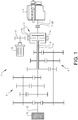
- Fig. 1 is a schematic view showing a driveline comprising a transmission 1 for a vehicle.
- the transmission 1 comprises a clutch unit 2 arranged for transferring torque from an internal combustion engine 3 to an input shaft 4, 5 of the transmission 1.
- the transmission 1 further comprises an electric motor 6 connected to the clutch unit 2 for transferring torque from the electric motor 6 to the input shaft 4, 5 through the clutch unit 2.
- ICE internal combustion engine
- the transmission 1 is part of a driveline comprising an internal combustion engine (ICE) for providing torque to the transmission
- ICE internal combustion engine
- another engine can be used instead of the ICE and full electric drivelines are possible.
- the clutch unit 2 in Fig. 1 is a dual clutch by which a crankshaft 7 of the ICE can be selectively connected to a first input shaft 4 and a second input shaft 5 of the transmission 1.
- a first set of gears 8 of the transmission can be used
- a second set of gears 9 of the transmission can be used.
- the first input shaft 4 can be an inner input shaft and the second input shaft 5 can be an outer input shaft, where the inner and outer input shafts are arranged concentrically relative to each other.
- the transmission 1 has also an output shaft 10 for transferring torque to wheels 11 of a vehicle as schematically illustrated in Fig. 1 .
- the transmission 1 has a first gear component 12, such as a gear wheel, driven by the electric motor 6 and a second gear component 13, such as a gear ring, rotationally locked to the clutch unit 2 by an engagement means 14.
- the engagement means 14 will be further described hereinafter with reference to Figs. 3a, 3b , 4a, 4b and 5 .
- the first gear component 12 and the second gear component 13 are engaged with each other for transferring torque from the electric motor 6 to the clutch unit 2, and further to some of the input shafts 4, 5.
- the transmission is exemplified by a dual clutch, it should be stressed that also other types of clutch unit can be used, such as for example a triple clutch.
- the second gear component 13 is suitably rotationally locked directly to an outer part 15 of the clutch unit 2, and preferably the second gear component 13 is rotationally locked to a casing 15 of the clutch unit 2.
- the crankshaft 7 of the ICE is also suitably connected to the casing 15 of the clutch unit 2 but in the centre of the clutch unit 2. This means that the second gear component 13 is arranged for rotating together with the internal combustion engine 3 when the internal combustion engine is connected to the clutch unit 2. In other words; the second gear component 13 and the crankshaft 7 will rotate with the same speed 20.
- a further clutch 80 can be arranged on the crankshaft 7 between the clutch unit 2 and the ICE.
- Fig. 2 shows an example embodiment of the transmission 1.
- the transmission 1 has a housing 20, a portion of which is shown in Fig. 2 .
- a rotor shaft 21 of the electric motor 6 is journaled by a bearing 22 arranged in the housing 20.
- the first gear component 12 is arranged on the rotor shaft 21.
- the second gear component 13 rotationally locked to the clutch unit 2 by the engagement means 14 is journaled by bearings 23, 24 arranged in the housing 20. Only the upper half of the clutch unit 2 is illustrated since the input shafts and the clutch unit are rotationally symmetrical with respect to a centre axis 28.
- the transmission 1 comprises at least one bearing 23 arranged for journaling the second gear component 13 and carrying radial load caused by the electric motor 6 when torque is transferred from the electric motor 6 to the clutch unit 2.
- the transmission 1 comprises one first bearing 23 arranged for journaling the second gear component 13 for carrying radial load and a second bearing 24 arranged for journaling the second gear component 13 for carrying axial load.
- the second gear component 13 suitably has a portion 25 extending from the engagement means 14 inwards in a radial direction towards the centre axis 28.
- radial direction is meant a direction perpendicular to the centre axis 28.
- the first bearing 23 is arranged between the housing 20 of the transmission 1 and a radial surface 26 of the second gear component portion 25 for transferring radial load from the second gear component 13 to the housing 20.
- the second bearing 24 is arranged between the housing 20 and an axial surface 27 of the second gear component portion 25 for transferring axial load from the second gear component 13 to the housing 20.
- the first bearing 23 can be a ball bearing and the second bearing 24 can be a roller thrust bearing.
- the first bearing 23 for transferring radial load from the second gear component 13 to the housing 20 can suitably be arranged radially inside of the engagement means 14, i.e. at a position closer to the centre axis 28 of the clutch unit 2 and the input shafts 4, 5 than the position of the engagement means 14.
- Figs. 3a and 3b show one example embodiment of an engagement means 14 for connecting the second gear component 13 driven by the electric motor 6 via the first gear component 12 and the clutch unit 2 of the transmission 1 to each other.
- Fig. 3a is a cut side view of the second gear component 13 and the clutch unit 2 being engaged to each other.
- Fig. 3b shows the second gear component 13 and the clutch unit 2 separated from each other in a cross-section view.
- the engagement means 14 can be a spline joint.
- the second gear component 13 is suitably a gear ring having teeth 50 arranged on an outer surface of the gear ring for engagement with the first gear component 12, and splines 51 arranged on an inner surface of the gear ring for engagement with the clutch unit 2.
- the clutch unit 2 is provided with corresponding external splines 52 for connection to the second gear component 13.
- the first gear component 12 connected to the second gear component 13 can be a chain instead of a gear wheel.
- the engagement means 14 is designed to allow a radial run out of the clutch unit 2 relative to the second gear component 13.
- the engagement means 14 can have a radial clearance between the second gear component 13 and the clutch unit 2.
- the engagement means 14 can have a radial clearance in the interval 0.05-0.5 mm, preferably 0.1-0.3 mm. Such a radial clearance will allow the clutch unit and the second gear component to be positioned non-concentrically relative to each other (due to a radial run out).
- At least one part of the engagement means can be flexible for allowing a radial run out of the clutch unit.
- Figs. 4a and 4b show a further example embodiment of an engagement means 14' for connecting the second gear component 13 driven by the electric motor 6 via the first gear component 12 and the clutch unit 2 of the transmission 1 to each other.
- Fig. 4a is a cut side view of the second gear component 13 and the clutch unit 2 being engaged to each other.
- Fig. 4b shows the second gear component 13, an element 60 of resilient material and the clutch unit 2 separated from each other in a cross-section view.
- the flexibility can be achieved by making said at least one engagement means part 60 from a resilient material, such as for example rubber.
- a resilient material such as for example rubber.
- Other material can also be used, such as plastics, thermoplastics for instance.
- Said at least one engagement means part has preferably a shore hardness Shore A in the interval 40-70 °Sh, preferably 50-60 °Sh.
- an element 60 of resilient material such as rubber, can be arranged between the second gear component 13 and the clutch unit 2.
- Such an element 60 can be a ring provided with protrusions 82 which ring is arranged between teeth 81 of the second gear component 13 and teeth 83 of the clutch unit 2.
- the second gear component teeth 81 can protrude in an axial direction from the second gear component and the clutch unit teeth 83 can protrude in an axial direction from the clutch unit.
- Such a ring 60 should withstand the shear stress when transferring the torque but be able to be compressed radially for allowing the radial run out as previously described.
- the resilient material can be arranged in grooves and/or on tips of splines between the second gear component and the clutch unit for allowing the radial run out, although the torque is transferred directly between the splines of the second gear component and the clutch unit, i.e. not through the engagement means part made of a resilient material.
- Fig. 5 shows a further example embodiment of the engagement means 14".
- said at least one engagement means part can have flexible fingers 70 for allowing a radial run out of the clutch unit 2.
- One of the second gear component 13 and the clutch unit 2 can have flexible fingers (the clutch unit 2 in the example embodiment illustrated in Fig. 5 ) and the other can have grooves 71 receiving the flexible fingers 70.
- These fingers 70 will transfer the torque between the second gear component 13 and the clutch unit 2 and at the same time they will be able to flex radially for allowing a radial run out.
- Such fingers 70 can be arranged on a disc 72 which in turn is attached to the clutch unit 2.
- the fingers are arranged along a circle and point in an axial direction.
- the number of fingers 70 and the space therebetween can be varied and of course adapted to the grooves 71 of the second gear component 13.
- Fig. 6 shows a further example embodiment of the transmission 1 where the second gear component 13 is journaled by one bearing 23' arranged in the housing 20 of the transmission 1.
- the bearing 23' is arranged substantially in line with the teeth 50 of the second gear component 13 as seen in the radial direction.
- the bearing diameter is of the same size as the diameter of spline joint 14 which is somewhat displaced in the axial direction relative to the bearing 23'.
- only one bearing 23' is used for carrying radial load and any axial load caused by the electric motor.
- Fig. 7 shows a further example embodiment where the second gear component 13 is journaled by one bearing 23" arranged in the housing 20 of the transmission 1.
- the bearing 23" is arranged axially displaced relative to the teeth 50 of the second gear component 13. Further, the bearing 23" has a diameter which is relatively small as compared to the diameter of the spline joint 14. In this example embodiment, only one bearing 23" is used for carrying radial load and any axial load caused by the electric motor 6.
Landscapes
- Engineering & Computer Science (AREA)
- Chemical & Material Sciences (AREA)
- Combustion & Propulsion (AREA)
- Transportation (AREA)
- Mechanical Engineering (AREA)
- Hybrid Electric Vehicles (AREA)
- Arrangement Of Transmissions (AREA)
Claims (21)
- Getriebe (1) für ein Fahrzeug, wobei das Getriebe eine mit einer Eingangswelle (4, 5) des Getriebes verbindbare Kupplungseinheit (2) und einen Elektromotor (6) umfasst, der mit der Kupplungseinheit verbunden ist, um ein Drehmoment vom Elektromotor durch die Kupplungseinheit auf die Eingangswelle zu übertragen, wobei das Getriebe (1) eine durch den Elektromotor (6) angetriebene erste Getriebekomponente (12) und eine zweite, durch ein Eingriffsmittel (14) drehbar an der Kupplungseinheit (2) gesicherte Getriebekomponente (13) umfasst, wobei die erste Getriebekomponente (12) und die zweite Getriebekomponente (13) miteinander in Eingriff stehen, um das Drehmoment vom Elektromotor (6) auf die Kupplungseinheit (2) zu übertragen, wobei das Getriebe weiter wenigstens ein Lager (23) umfasst, das zur Lagerung der zweiten Getriebekomponente (13) und zum Tragen einer vom Elektromotor verursachten Radiallast angeordnet ist, wenn das Drehmoment vom Elektromotor auf die Kupplungseinheit übertragen wird, wobei das Eingriffsmittel (14) einen Radialschlag der Kupplungseinheit (2) relativ zur zweiten Getriebekomponente (13) ermöglicht, dadurch gekennzeichnet, dass wenigstens ein Teil (60; 70) des Eingriffsmittels flexibel ist, damit ein Radialschlag der Kupplungseinheit (2) ermöglicht wird.
- Getriebe nach Anspruch 1, dadurch gekennzeichnet, dass das Eingriffsmittel (14) ein radiales Spiel zwischen der zweiten Getriebekomponente und der Kupplungseinheit aufweist.
- Getriebe nach Anspruch 2, dadurch gekennzeichnet, dass das Eingriffsmittel (14) ein radiales Spiel im Intervall 0,05-0,5 mm, vorzugsweise 0,1-0,3 mm, aufweist.
- Getriebe nach einem der Ansprüche 1 bis 3, dadurch gekennzeichnet, dass der wenigstens eine Eingriffsmittelteil (60) aus einem nachgiebigen Material gefertigt ist.
- Getriebe nach Anspruch 4, dadurch gekennzeichnet, dass der wenigstens eine Eingriffsmittelteil (60) aus Gummi gefertigt ist.
- Getriebe nach Anspruch 4 oder 5, dadurch gekennzeichnet, dass der wenigstens eine Eingriffsmittelteil (60) eine Shore-Härte Shore A im Intervall 40-70 °Sh aufweist.
- Getriebe nach einem der Ansprüche 1 bis 6, dadurch gekennzeichnet, dass der wenigstens eine Eingriffsmittelteil flexible Finger (70) zur Ermöglichung eines Radialschlags der Kupplungseinheit (2) aufweist.
- Getriebe nach einem der vorhergehenden Ansprüche, dadurch gekennzeichnet, dass das Eingriffsmittel (14) eine Keilverbindung ist.
- Getriebe nach Anspruch 8, dadurch gekennzeichnet, dass die zweite Getriebekomponente (13) ein Zahnkranz ist, der Zähne (50), die auf einer Außenfläche des Zahnkranzes zum Eingriff mit der ersten Getriebekomponente (12) angeordnet sind, und Keile (51), die auf einer Innenfläche des Zahnkranzes zum Eingriff mit der Kupplungseinheit (2) angeordnet sind, aufweist.
- Getriebe nach Anspruch 9, dadurch gekennzeichnet, dass das wenigstens eine zweite Getriebekomponentenlager (23') im Wesentlichen fluchtend mit den Zähnen (50) der zweiten Getriebekomponente (13) in einer Radialrichtung angeordnet ist.
- Getriebe nach Anspruch 9, dadurch gekennzeichnet, dass das wenigstens eine zweite Getriebekomponentenlager (23") relativ zu den Zähnen (50) der zweiten Getriebekomponente (13) axial versetzt angeordnet ist.
- Getriebe nach einem der vorhergehenden Ansprüche, dadurch gekennzeichnet, dass das wenigstens eine zweite Getriebekomponentenlager (23) in einem Gehäuse (20) des Getriebes (1) untergebracht ist, wobei das Getriebe ein oder mehrere zur Lagerung einer Rotorwelle (21) des Elektromotors (6) angeordnete Lager (22) umfasst, wobei die Lager (22) des Elektromotors in dem Gehäuse (20) untergebracht sind.
- Getriebe nach einem der vorhergehenden Ansprüche, dadurch gekennzeichnet, dass das wenigstens eine zweite Getriebekomponentenlager (23) radial innerhalb des Eingriffsmittels (14) angeordnet ist.
- Getriebe nach einem der vorhergehenden Ansprüche, dadurch gekennzeichnet, dass das Getriebe (1) ein erstes Lager (23), das zur Lagerung der zweiten Getriebekomponente (13) zum Tragen der Radiallast angeordnet ist, und ein zweites Lager (24), das zur Lagerung der zweiten Getriebekomponente (13) zum Tragen der Axiallast angeordnet ist, umfasst.
- Getriebe nach Anspruch 14, dadurch gekennzeichnet, dass die zweite Getriebekomponente (13) einen sich vom Eingriffsmittel (14) nach innen in der Radialrichtung erstreckenden Abschnitt (25) aufweist, wobei das erste Lager (23) zwischen einem Gehäuse (20) des Getriebes (1) und einer radialen Oberfläche (26) des zweiten Getriebekomponententeils (25) zum Übertragen der Radiallast von der zweiten Getriebekomponente auf das Gehäuse angeordnet ist, und das zweite Lager (24) zwischen dem Gehäuse (20) und einer axialen Oberfläche (27) des zweiten Getriebekomponententeils (25) zum Übertragen der Axiallast von der zweiten Getriebekomponente auf das Gehäuse angeordnet ist.
- Getriebe nach Anspruch 14 oder 15, dadurch gekennzeichnet, dass das erste Lager (23) ein Kugellager ist, und das zweite Lager (24) ein Druckrollenlager ist.
- Getriebe nach einem der vorhergehenden Ansprüche, dadurch gekennzeichnet, dass die zweite Getriebekomponente (13) direkt an einem Außenteil (15) der Kupplungseinheit (2) drehbar gesichert ist.
- Getriebe nach einem der vorhergehenden Ansprüche, dadurch gekennzeichnet, dass die zweite Getriebekomponente (13) an einer Bekleidung (15) der Kupplungseinheit (2) drehbar gesichert ist.
- Getriebe nach einem der vorhergehenden Ansprüche, dadurch gekennzeichnet, dass die Kupplungseinheit (2) eine Doppelkupplung ist.
- Getriebe nach einem der vorhergehenden Ansprüche, dadurch gekennzeichnet, dass die erste Getriebekomponente (12) ein Zahnrad ist.
- Antriebsstrang umfassend ein Getriebe (1) nach einem der Ansprüche 1-20, wobei der Antriebsstrang einen mit der Kupplungseinheit (2) verbindbaren Motor (3) umfasst, wobei die zweite Getriebekomponente (13) zur Drehung mit der gleichen Geschwindigkeit wie der Motor (3) angeordnet ist, wenn der Motor mit der Kupplungseinheit verbunden ist.
Priority Applications (4)
| Application Number | Priority Date | Filing Date | Title |
|---|---|---|---|
| EP18177579.2A EP3581417B1 (de) | 2018-06-13 | 2018-06-13 | Getriebe für ein fahrzeug |
| CN201980038522.1A CN112262053B (zh) | 2018-06-13 | 2019-05-30 | 用于车辆的变速器 |
| PCT/CN2019/089267 WO2019237937A1 (en) | 2018-06-13 | 2019-05-30 | A transmission for a vehicle |
| US17/112,059 US11230181B2 (en) | 2018-06-13 | 2020-12-04 | Transmission for a vehicle |
Applications Claiming Priority (1)
| Application Number | Priority Date | Filing Date | Title |
|---|---|---|---|
| EP18177579.2A EP3581417B1 (de) | 2018-06-13 | 2018-06-13 | Getriebe für ein fahrzeug |
Publications (2)
| Publication Number | Publication Date |
|---|---|
| EP3581417A1 EP3581417A1 (de) | 2019-12-18 |
| EP3581417B1 true EP3581417B1 (de) | 2021-05-05 |
Family
ID=62631030
Family Applications (1)
| Application Number | Title | Priority Date | Filing Date |
|---|---|---|---|
| EP18177579.2A Active EP3581417B1 (de) | 2018-06-13 | 2018-06-13 | Getriebe für ein fahrzeug |
Country Status (4)
| Country | Link |
|---|---|
| US (1) | US11230181B2 (de) |
| EP (1) | EP3581417B1 (de) |
| CN (1) | CN112262053B (de) |
| WO (1) | WO2019237937A1 (de) |
Family Cites Families (18)
| Publication number | Priority date | Publication date | Assignee | Title |
|---|---|---|---|---|
| JP3691717B2 (ja) * | 2000-03-22 | 2005-09-07 | ジヤトコ株式会社 | ハイブリッド車両の変速機ユニット |
| US6428438B1 (en) * | 2000-07-26 | 2002-08-06 | New Venture Gear, Inc. | Hybrid automated manual transmission |
| CN100491148C (zh) * | 2006-06-22 | 2009-05-27 | 浙江吉利汽车研究院有限公司 | 混合动力系统 |
| CN201212541Y (zh) * | 2008-04-03 | 2009-03-25 | 刘珍利 | 离合器轮毂与从动齿轮的装配结构 |
| DE102008047288A1 (de) * | 2008-09-16 | 2010-04-15 | Dr.Ing.H.C.F.Porsche Aktiengesellschaft | Hybridantrieb für ein Fahrzeug |
| DE102008048801B3 (de) * | 2008-09-24 | 2010-06-17 | Getrag Ford Transmissions Gmbh | Abstützelement für eine Kupplungsvorrichtung mit zwei Reibkupplungen |
| DE112009002360B4 (de) * | 2009-04-28 | 2015-11-26 | Toyota Jidosha Kabushiki Kaisha | Öldurchgangsstruktur einer Ölpumpe mit Kettenantrieb |
| JP5533410B2 (ja) * | 2010-08-04 | 2014-06-25 | トヨタ自動車株式会社 | 車両用駆動装置 |
| CN202301522U (zh) * | 2011-06-22 | 2012-07-04 | 上海汽车集团股份有限公司 | 连接装置和传动装置 |
| US8545355B2 (en) * | 2011-10-11 | 2013-10-01 | Ford Global Technologies, Llc | Assembly method for hybrid electric transmission |
| WO2014037018A1 (en) * | 2012-09-05 | 2014-03-13 | Volvo Lastvagnar Ab | A powertrain for a hybrid vehicle and a method for control of the powertrain |
| DE102013022142A1 (de) * | 2013-12-19 | 2015-06-25 | Getrag Getriebe- Und Zahnradfabrik Hermann Hagenmeyer Gmbh & Cie Kg | Hybrid-Antriebsstrang für ein Kraftfahrzeug |
| JP2015140127A (ja) * | 2014-01-30 | 2015-08-03 | アイシン・エーアイ株式会社 | ハイブリッド車両用変速機 |
| DE102014014236A1 (de) * | 2014-02-22 | 2015-08-27 | Borgwarner Inc. | Antriebsstrang für ein Kraftfahrzeug und Verfahren zum Betrieb eines solchen Antriebsstrangs |
| CN104786819A (zh) * | 2015-03-10 | 2015-07-22 | 重庆长安汽车股份有限公司 | 一种车辆及其高度集成的混合动力驱动系统 |
| DE102016002908A1 (de) * | 2015-04-14 | 2016-10-20 | Borgwarner Inc. | Antriebsstang für ein Hybridfahrzeug |
| DE102016211270A1 (de) * | 2016-06-23 | 2017-12-28 | Zf Friedrichshafen Ag | Planetenradsatzsystem für ein Kraftfahrzeuggetriebe, Getriebe für ein Kraftfahrzeug mit einem solchen Planetenradsatzsystem, und Antriebsstrang für ein Kraftfahrzeug |
| DE102016211884A1 (de) * | 2016-06-30 | 2018-01-04 | Zf Friedrichshafen Ag | Getriebe für ein Kraftfahrzeug, sowie Antriebsstrang für ein Kraftfahrzeug |
-
2018
- 2018-06-13 EP EP18177579.2A patent/EP3581417B1/de active Active
-
2019
- 2019-05-30 WO PCT/CN2019/089267 patent/WO2019237937A1/en not_active Ceased
- 2019-05-30 CN CN201980038522.1A patent/CN112262053B/zh active Active
-
2020
- 2020-12-04 US US17/112,059 patent/US11230181B2/en active Active
Also Published As
| Publication number | Publication date |
|---|---|
| US20210086606A1 (en) | 2021-03-25 |
| CN112262053A (zh) | 2021-01-22 |
| WO2019237937A1 (en) | 2019-12-19 |
| EP3581417A1 (de) | 2019-12-18 |
| US11230181B2 (en) | 2022-01-25 |
| CN112262053B (zh) | 2022-07-19 |
Similar Documents
| Publication | Publication Date | Title |
|---|---|---|
| AU2018201255B2 (en) | Assembly having a clutch collar and method of manufacture | |
| EP3453906B1 (de) | Verbindung zur drehmomentübertragung und elektrische servolenkvorrichtung | |
| JP5879773B2 (ja) | カップリング装置 | |
| EP3571421B1 (de) | Halter für rotierende elemente | |
| WO2007133369A2 (en) | Centrifugal clutch | |
| US7413067B2 (en) | Dog clutch | |
| EP4455517A2 (de) | Achsanordnung mit schaltmuffe | |
| EP1853832B1 (de) | Verbindungsanordnung mit zentrierflansch | |
| US11703114B2 (en) | Differential gearbox | |
| US11230181B2 (en) | Transmission for a vehicle | |
| US7565958B1 (en) | Torque converter race kit | |
| EP3670225B1 (de) | Fahrzeugantriebsstrangsystem | |
| CN107709811A (zh) | 带有扭转减振器的变速器 | |
| US11938811B2 (en) | Multi-stage shifting actuator for a vehicle power transfer unit | |
| CN109780072B (zh) | 驱动器及其一体式联轴器 | |
| JP2024510248A5 (de) | ||
| EP3341631B1 (de) | Lastverteilungsvorrichtung | |
| CN112747087A (zh) | 行星齿轮系统、扭转保险装置及操作传动系统的方法 | |
| CN222254787U (zh) | 一种复合用途离合器 | |
| CN111356850B (zh) | 变速器输入轴装置 | |
| CN216112045U (zh) | 一种变速器中间轴及变速器 | |
| JPH10246119A (ja) | 羽根車 | |
| JP2007333049A (ja) | スプライン連結構造 | |
| CN119343549A (zh) | 差动组件和车辆以及用于组装差动组件的方法 | |
| CN114341512A (zh) | 具有同中心地布置的滚动轴承的扭矩传递系统、驱动单元和驱动组件 |
Legal Events
| Date | Code | Title | Description |
|---|---|---|---|
| PUAI | Public reference made under article 153(3) epc to a published international application that has entered the european phase |
Free format text: ORIGINAL CODE: 0009012 |
|
| STAA | Information on the status of an ep patent application or granted ep patent |
Free format text: STATUS: REQUEST FOR EXAMINATION WAS MADE |
|
| 17P | Request for examination filed |
Effective date: 20180613 |
|
| AK | Designated contracting states |
Kind code of ref document: A1 Designated state(s): AL AT BE BG CH CY CZ DE DK EE ES FI FR GB GR HR HU IE IS IT LI LT LU LV MC MK MT NL NO PL PT RO RS SE SI SK SM TR |
|
| AX | Request for extension of the european patent |
Extension state: BA ME |
|
| GRAP | Despatch of communication of intention to grant a patent |
Free format text: ORIGINAL CODE: EPIDOSNIGR1 |
|
| STAA | Information on the status of an ep patent application or granted ep patent |
Free format text: STATUS: GRANT OF PATENT IS INTENDED |
|
| RIC1 | Information provided on ipc code assigned before grant |
Ipc: F16D 1/10 20060101ALN20210120BHEP Ipc: F16D 3/04 20060101ALN20210120BHEP Ipc: B60K 6/387 20071001ALN20210120BHEP Ipc: F16H 57/021 20120101ALN20210120BHEP Ipc: B60K 6/48 20071001AFI20210120BHEP Ipc: F16D 3/18 20060101ALN20210120BHEP Ipc: B60K 6/40 20071001ALN20210120BHEP |
|
| INTG | Intention to grant announced |
Effective date: 20210224 |
|
| GRAS | Grant fee paid |
Free format text: ORIGINAL CODE: EPIDOSNIGR3 |
|
| GRAA | (expected) grant |
Free format text: ORIGINAL CODE: 0009210 |
|
| STAA | Information on the status of an ep patent application or granted ep patent |
Free format text: STATUS: THE PATENT HAS BEEN GRANTED |
|
| AK | Designated contracting states |
Kind code of ref document: B1 Designated state(s): AL AT BE BG CH CY CZ DE DK EE ES FI FR GB GR HR HU IE IS IT LI LT LU LV MC MK MT NL NO PL PT RO RS SE SI SK SM TR |
|
| REG | Reference to a national code |
Ref country code: GB Ref legal event code: FG4D |
|
| REG | Reference to a national code |
Ref country code: CH Ref legal event code: EP |
|
| REG | Reference to a national code |
Ref country code: AT Ref legal event code: REF Ref document number: 1389390 Country of ref document: AT Kind code of ref document: T Effective date: 20210515 |
|
| REG | Reference to a national code |
Ref country code: IE Ref legal event code: FG4D |
|
| REG | Reference to a national code |
Ref country code: DE Ref legal event code: R096 Ref document number: 602018016493 Country of ref document: DE |
|
| REG | Reference to a national code |
Ref country code: LT Ref legal event code: MG9D |
|
| REG | Reference to a national code |
Ref country code: AT Ref legal event code: MK05 Ref document number: 1389390 Country of ref document: AT Kind code of ref document: T Effective date: 20210505 |
|
| PG25 | Lapsed in a contracting state [announced via postgrant information from national office to epo] |
Ref country code: FI Free format text: LAPSE BECAUSE OF FAILURE TO SUBMIT A TRANSLATION OF THE DESCRIPTION OR TO PAY THE FEE WITHIN THE PRESCRIBED TIME-LIMIT Effective date: 20210505 Ref country code: HR Free format text: LAPSE BECAUSE OF FAILURE TO SUBMIT A TRANSLATION OF THE DESCRIPTION OR TO PAY THE FEE WITHIN THE PRESCRIBED TIME-LIMIT Effective date: 20210505 Ref country code: LT Free format text: LAPSE BECAUSE OF FAILURE TO SUBMIT A TRANSLATION OF THE DESCRIPTION OR TO PAY THE FEE WITHIN THE PRESCRIBED TIME-LIMIT Effective date: 20210505 Ref country code: BG Free format text: LAPSE BECAUSE OF FAILURE TO SUBMIT A TRANSLATION OF THE DESCRIPTION OR TO PAY THE FEE WITHIN THE PRESCRIBED TIME-LIMIT Effective date: 20210805 Ref country code: AT Free format text: LAPSE BECAUSE OF FAILURE TO SUBMIT A TRANSLATION OF THE DESCRIPTION OR TO PAY THE FEE WITHIN THE PRESCRIBED TIME-LIMIT Effective date: 20210505 |
|
| PG25 | Lapsed in a contracting state [announced via postgrant information from national office to epo] |
Ref country code: IS Free format text: LAPSE BECAUSE OF FAILURE TO SUBMIT A TRANSLATION OF THE DESCRIPTION OR TO PAY THE FEE WITHIN THE PRESCRIBED TIME-LIMIT Effective date: 20210905 Ref country code: GR Free format text: LAPSE BECAUSE OF FAILURE TO SUBMIT A TRANSLATION OF THE DESCRIPTION OR TO PAY THE FEE WITHIN THE PRESCRIBED TIME-LIMIT Effective date: 20210806 Ref country code: RS Free format text: LAPSE BECAUSE OF FAILURE TO SUBMIT A TRANSLATION OF THE DESCRIPTION OR TO PAY THE FEE WITHIN THE PRESCRIBED TIME-LIMIT Effective date: 20210505 Ref country code: SE Free format text: LAPSE BECAUSE OF FAILURE TO SUBMIT A TRANSLATION OF THE DESCRIPTION OR TO PAY THE FEE WITHIN THE PRESCRIBED TIME-LIMIT Effective date: 20210505 Ref country code: LV Free format text: LAPSE BECAUSE OF FAILURE TO SUBMIT A TRANSLATION OF THE DESCRIPTION OR TO PAY THE FEE WITHIN THE PRESCRIBED TIME-LIMIT Effective date: 20210505 Ref country code: NO Free format text: LAPSE BECAUSE OF FAILURE TO SUBMIT A TRANSLATION OF THE DESCRIPTION OR TO PAY THE FEE WITHIN THE PRESCRIBED TIME-LIMIT Effective date: 20210805 Ref country code: PL Free format text: LAPSE BECAUSE OF FAILURE TO SUBMIT A TRANSLATION OF THE DESCRIPTION OR TO PAY THE FEE WITHIN THE PRESCRIBED TIME-LIMIT Effective date: 20210505 Ref country code: PT Free format text: LAPSE BECAUSE OF FAILURE TO SUBMIT A TRANSLATION OF THE DESCRIPTION OR TO PAY THE FEE WITHIN THE PRESCRIBED TIME-LIMIT Effective date: 20210906 |
|
| REG | Reference to a national code |
Ref country code: NL Ref legal event code: MP Effective date: 20210505 |
|
| PG25 | Lapsed in a contracting state [announced via postgrant information from national office to epo] |
Ref country code: NL Free format text: LAPSE BECAUSE OF FAILURE TO SUBMIT A TRANSLATION OF THE DESCRIPTION OR TO PAY THE FEE WITHIN THE PRESCRIBED TIME-LIMIT Effective date: 20210505 |
|
| PG25 | Lapsed in a contracting state [announced via postgrant information from national office to epo] |
Ref country code: ES Free format text: LAPSE BECAUSE OF FAILURE TO SUBMIT A TRANSLATION OF THE DESCRIPTION OR TO PAY THE FEE WITHIN THE PRESCRIBED TIME-LIMIT Effective date: 20210505 Ref country code: EE Free format text: LAPSE BECAUSE OF FAILURE TO SUBMIT A TRANSLATION OF THE DESCRIPTION OR TO PAY THE FEE WITHIN THE PRESCRIBED TIME-LIMIT Effective date: 20210505 Ref country code: SM Free format text: LAPSE BECAUSE OF FAILURE TO SUBMIT A TRANSLATION OF THE DESCRIPTION OR TO PAY THE FEE WITHIN THE PRESCRIBED TIME-LIMIT Effective date: 20210505 Ref country code: SK Free format text: LAPSE BECAUSE OF FAILURE TO SUBMIT A TRANSLATION OF THE DESCRIPTION OR TO PAY THE FEE WITHIN THE PRESCRIBED TIME-LIMIT Effective date: 20210505 Ref country code: RO Free format text: LAPSE BECAUSE OF FAILURE TO SUBMIT A TRANSLATION OF THE DESCRIPTION OR TO PAY THE FEE WITHIN THE PRESCRIBED TIME-LIMIT Effective date: 20210505 Ref country code: CZ Free format text: LAPSE BECAUSE OF FAILURE TO SUBMIT A TRANSLATION OF THE DESCRIPTION OR TO PAY THE FEE WITHIN THE PRESCRIBED TIME-LIMIT Effective date: 20210505 Ref country code: DK Free format text: LAPSE BECAUSE OF FAILURE TO SUBMIT A TRANSLATION OF THE DESCRIPTION OR TO PAY THE FEE WITHIN THE PRESCRIBED TIME-LIMIT Effective date: 20210505 |
|
| REG | Reference to a national code |
Ref country code: CH Ref legal event code: PL |
|
| REG | Reference to a national code |
Ref country code: DE Ref legal event code: R097 Ref document number: 602018016493 Country of ref document: DE |
|
| REG | Reference to a national code |
Ref country code: BE Ref legal event code: MM Effective date: 20210630 |
|
| PLBE | No opposition filed within time limit |
Free format text: ORIGINAL CODE: 0009261 |
|
| STAA | Information on the status of an ep patent application or granted ep patent |
Free format text: STATUS: NO OPPOSITION FILED WITHIN TIME LIMIT |
|
| PG25 | Lapsed in a contracting state [announced via postgrant information from national office to epo] |
Ref country code: MC Free format text: LAPSE BECAUSE OF FAILURE TO SUBMIT A TRANSLATION OF THE DESCRIPTION OR TO PAY THE FEE WITHIN THE PRESCRIBED TIME-LIMIT Effective date: 20210505 Ref country code: LU Free format text: LAPSE BECAUSE OF NON-PAYMENT OF DUE FEES Effective date: 20210613 |
|
| 26N | No opposition filed |
Effective date: 20220208 |
|
| PG25 | Lapsed in a contracting state [announced via postgrant information from national office to epo] |
Ref country code: LI Free format text: LAPSE BECAUSE OF NON-PAYMENT OF DUE FEES Effective date: 20210630 Ref country code: IE Free format text: LAPSE BECAUSE OF NON-PAYMENT OF DUE FEES Effective date: 20210613 Ref country code: CH Free format text: LAPSE BECAUSE OF NON-PAYMENT OF DUE FEES Effective date: 20210630 |
|
| PG25 | Lapsed in a contracting state [announced via postgrant information from national office to epo] |
Ref country code: IS Free format text: LAPSE BECAUSE OF FAILURE TO SUBMIT A TRANSLATION OF THE DESCRIPTION OR TO PAY THE FEE WITHIN THE PRESCRIBED TIME-LIMIT Effective date: 20210905 Ref country code: AL Free format text: LAPSE BECAUSE OF FAILURE TO SUBMIT A TRANSLATION OF THE DESCRIPTION OR TO PAY THE FEE WITHIN THE PRESCRIBED TIME-LIMIT Effective date: 20210505 |
|
| PG25 | Lapsed in a contracting state [announced via postgrant information from national office to epo] |
Ref country code: IT Free format text: LAPSE BECAUSE OF FAILURE TO SUBMIT A TRANSLATION OF THE DESCRIPTION OR TO PAY THE FEE WITHIN THE PRESCRIBED TIME-LIMIT Effective date: 20210505 Ref country code: BE Free format text: LAPSE BECAUSE OF NON-PAYMENT OF DUE FEES Effective date: 20210630 |
|
| PG25 | Lapsed in a contracting state [announced via postgrant information from national office to epo] |
Ref country code: CY Free format text: LAPSE BECAUSE OF FAILURE TO SUBMIT A TRANSLATION OF THE DESCRIPTION OR TO PAY THE FEE WITHIN THE PRESCRIBED TIME-LIMIT Effective date: 20210505 |
|
| PG25 | Lapsed in a contracting state [announced via postgrant information from national office to epo] |
Ref country code: HU Free format text: LAPSE BECAUSE OF FAILURE TO SUBMIT A TRANSLATION OF THE DESCRIPTION OR TO PAY THE FEE WITHIN THE PRESCRIBED TIME-LIMIT; INVALID AB INITIO Effective date: 20180613 |
|
| PG25 | Lapsed in a contracting state [announced via postgrant information from national office to epo] |
Ref country code: MK Free format text: LAPSE BECAUSE OF FAILURE TO SUBMIT A TRANSLATION OF THE DESCRIPTION OR TO PAY THE FEE WITHIN THE PRESCRIBED TIME-LIMIT Effective date: 20210505 |
|
| PG25 | Lapsed in a contracting state [announced via postgrant information from national office to epo] |
Ref country code: MT Free format text: LAPSE BECAUSE OF FAILURE TO SUBMIT A TRANSLATION OF THE DESCRIPTION OR TO PAY THE FEE WITHIN THE PRESCRIBED TIME-LIMIT Effective date: 20210505 |
|
| PGFP | Annual fee paid to national office [announced via postgrant information from national office to epo] |
Ref country code: DE Payment date: 20250618 Year of fee payment: 8 |
|
| PGFP | Annual fee paid to national office [announced via postgrant information from national office to epo] |
Ref country code: GB Payment date: 20250402 Year of fee payment: 8 |
|
| PGFP | Annual fee paid to national office [announced via postgrant information from national office to epo] |
Ref country code: FR Payment date: 20250515 Year of fee payment: 8 |
|
| PG25 | Lapsed in a contracting state [announced via postgrant information from national office to epo] |
Ref country code: TR Free format text: LAPSE BECAUSE OF FAILURE TO SUBMIT A TRANSLATION OF THE DESCRIPTION OR TO PAY THE FEE WITHIN THE PRESCRIBED TIME-LIMIT Effective date: 20210505 |