EP3581697B1 - Fotoaktivierungsvorrichtung für waschmaschine - Google Patents
Fotoaktivierungsvorrichtung für waschmaschine Download PDFInfo
- Publication number
- EP3581697B1 EP3581697B1 EP18176903.5A EP18176903A EP3581697B1 EP 3581697 B1 EP3581697 B1 EP 3581697B1 EP 18176903 A EP18176903 A EP 18176903A EP 3581697 B1 EP3581697 B1 EP 3581697B1
- Authority
- EP
- European Patent Office
- Prior art keywords
- photoactivating device
- light source
- photoactivating
- controller
- sensing unit
- Prior art date
- Legal status (The legal status is an assumption and is not a legal conclusion. Google has not performed a legal analysis and makes no representation as to the accuracy of the status listed.)
- Active
Links
Images


Classifications
-
- D—TEXTILES; PAPER
- D06—TREATMENT OF TEXTILES OR THE LIKE; LAUNDERING; FLEXIBLE MATERIALS NOT OTHERWISE PROVIDED FOR
- D06F—LAUNDERING, DRYING, IRONING, PRESSING OR FOLDING TEXTILE ARTICLES
- D06F39/00—Details of washing machines not specific to a single type of machines covered by groups D06F9/00 - D06F27/00
- D06F39/02—Devices for adding soap or other washing agents
- D06F39/024—Devices for adding soap or other washing agents mounted on the agitator or the rotating drum; Free body dispensers
-
- B—PERFORMING OPERATIONS; TRANSPORTING
- B65—CONVEYING; PACKING; STORING; HANDLING THIN OR FILAMENTARY MATERIAL
- B65D—CONTAINERS FOR STORAGE OR TRANSPORT OF ARTICLES OR MATERIALS, e.g. BAGS, BARRELS, BOTTLES, BOXES, CANS, CARTONS, CRATES, DRUMS, JARS, TANKS, HOPPERS, FORWARDING CONTAINERS; ACCESSORIES, CLOSURES, OR FITTINGS THEREFOR; PACKAGING ELEMENTS; PACKAGES
- B65D23/00—Details of bottles or jars not otherwise provided for
- B65D23/10—Handles
- B65D23/102—Gripping means formed in the walls, e.g. roughening, cavities, projections
-
- B—PERFORMING OPERATIONS; TRANSPORTING
- B65—CONVEYING; PACKING; STORING; HANDLING THIN OR FILAMENTARY MATERIAL
- B65D—CONTAINERS FOR STORAGE OR TRANSPORT OF ARTICLES OR MATERIALS, e.g. BAGS, BARRELS, BOTTLES, BOXES, CANS, CARTONS, CRATES, DRUMS, JARS, TANKS, HOPPERS, FORWARDING CONTAINERS; ACCESSORIES, CLOSURES, OR FITTINGS THEREFOR; PACKAGING ELEMENTS; PACKAGES
- B65D51/00—Closures not otherwise provided for
- B65D51/24—Closures not otherwise provided for combined or co-operating with auxiliary devices for non-closing purposes
-
- C—CHEMISTRY; METALLURGY
- C11—ANIMAL OR VEGETABLE OILS, FATS, FATTY SUBSTANCES OR WAXES; FATTY ACIDS THEREFROM; DETERGENTS; CANDLES
- C11D—DETERGENT COMPOSITIONS; USE OF SINGLE SUBSTANCES AS DETERGENTS; SOAP OR SOAP-MAKING; RESIN SOAPS; RECOVERY OF GLYCEROL
- C11D17/00—Detergent materials or soaps characterised by their shape or physical properties
- C11D17/04—Detergent materials or soaps characterised by their shape or physical properties combined with or containing other objects
- C11D17/041—Compositions releasably affixed on a substrate or incorporated into a dispensing means
- C11D17/046—Insoluble free body dispenser
-
- C—CHEMISTRY; METALLURGY
- C11—ANIMAL OR VEGETABLE OILS, FATS, FATTY SUBSTANCES OR WAXES; FATTY ACIDS THEREFROM; DETERGENTS; CANDLES
- C11D—DETERGENT COMPOSITIONS; USE OF SINGLE SUBSTANCES AS DETERGENTS; SOAP OR SOAP-MAKING; RESIN SOAPS; RECOVERY OF GLYCEROL
- C11D3/00—Other compounding ingredients of detergent compositions covered in group C11D1/00
- C11D3/0005—Other compounding ingredients characterised by their effect
- C11D3/0063—Photo- activating compounds
-
- C—CHEMISTRY; METALLURGY
- C11—ANIMAL OR VEGETABLE OILS, FATS, FATTY SUBSTANCES OR WAXES; FATTY ACIDS THEREFROM; DETERGENTS; CANDLES
- C11D—DETERGENT COMPOSITIONS; USE OF SINGLE SUBSTANCES AS DETERGENTS; SOAP OR SOAP-MAKING; RESIN SOAPS; RECOVERY OF GLYCEROL
- C11D3/00—Other compounding ingredients of detergent compositions covered in group C11D1/00
- C11D3/16—Organic compounds
- C11D3/20—Organic compounds containing oxygen
- C11D3/2096—Heterocyclic compounds
-
- C—CHEMISTRY; METALLURGY
- C11—ANIMAL OR VEGETABLE OILS, FATS, FATTY SUBSTANCES OR WAXES; FATTY ACIDS THEREFROM; DETERGENTS; CANDLES
- C11D—DETERGENT COMPOSITIONS; USE OF SINGLE SUBSTANCES AS DETERGENTS; SOAP OR SOAP-MAKING; RESIN SOAPS; RECOVERY OF GLYCEROL
- C11D3/00—Other compounding ingredients of detergent compositions covered in group C11D1/00
- C11D3/16—Organic compounds
- C11D3/24—Organic compounds containing halogen
-
- C—CHEMISTRY; METALLURGY
- C11—ANIMAL OR VEGETABLE OILS, FATS, FATTY SUBSTANCES OR WAXES; FATTY ACIDS THEREFROM; DETERGENTS; CANDLES
- C11D—DETERGENT COMPOSITIONS; USE OF SINGLE SUBSTANCES AS DETERGENTS; SOAP OR SOAP-MAKING; RESIN SOAPS; RECOVERY OF GLYCEROL
- C11D3/00—Other compounding ingredients of detergent compositions covered in group C11D1/00
- C11D3/16—Organic compounds
- C11D3/26—Organic compounds containing nitrogen
- C11D3/28—Heterocyclic compounds containing nitrogen in the ring
-
- C—CHEMISTRY; METALLURGY
- C11—ANIMAL OR VEGETABLE OILS, FATS, FATTY SUBSTANCES OR WAXES; FATTY ACIDS THEREFROM; DETERGENTS; CANDLES
- C11D—DETERGENT COMPOSITIONS; USE OF SINGLE SUBSTANCES AS DETERGENTS; SOAP OR SOAP-MAKING; RESIN SOAPS; RECOVERY OF GLYCEROL
- C11D2111/00—Cleaning compositions characterised by the objects to be cleaned; Cleaning compositions characterised by non-standard cleaning or washing processes
- C11D2111/10—Objects to be cleaned
- C11D2111/12—Soft surfaces, e.g. textile
-
- D—TEXTILES; PAPER
- D06—TREATMENT OF TEXTILES OR THE LIKE; LAUNDERING; FLEXIBLE MATERIALS NOT OTHERWISE PROVIDED FOR
- D06F—LAUNDERING, DRYING, IRONING, PRESSING OR FOLDING TEXTILE ARTICLES
- D06F2103/00—Parameters monitored or detected for the control of domestic laundry washing machines, washer-dryers or laundry dryers
- D06F2103/24—Spin speed; Drum movements
-
- D—TEXTILES; PAPER
- D06—TREATMENT OF TEXTILES OR THE LIKE; LAUNDERING; FLEXIBLE MATERIALS NOT OTHERWISE PROVIDED FOR
- D06F—LAUNDERING, DRYING, IRONING, PRESSING OR FOLDING TEXTILE ARTICLES
- D06F2105/00—Systems or parameters controlled or affected by the control systems of washing machines, washer-dryers or laundry dryers
- D06F2105/42—Detergent or additive supply
-
- H—ELECTRICITY
- H02—GENERATION; CONVERSION OR DISTRIBUTION OF ELECTRIC POWER
- H02J—ELECTRIC POWER NETWORKS; CIRCUIT ARRANGEMENTS OR SYSTEMS FOR SUPPLYING OR DISTRIBUTING ELECTRIC POWER; SYSTEMS FOR STORING ELECTRIC ENERGY
- H02J50/00—Circuit arrangements or systems for wireless supply or distribution of electric power
- H02J50/10—Circuit arrangements or systems for wireless supply or distribution of electric power using inductive coupling
Definitions
- Photoactivating device for activation of one or more photoactive components contained in a laundry treatment composition for placement within a laundering space of a washing machine, optionally wherein the photoactivating device has photoactivating capability.
- a problem in the art is an effective and even activation of the photoactive component within the wash solvent (e.g. water).
- the wash solvent e.g. water
- an activating light source When an activating light source is provided as a fixed arrangement within the washing machine, it will activate photoactive component only in the vicinity of the fixed source, meaning that the laundry articles and wash solvent (e.g. water) need to be thoroughly agitated to ensure an even exposure to the light source.
- a further problem in the art is local effects of photoactivation products such as bleaching; where the light source shines for too long or too intensely, laundry articles too close to the light source may become whitened locally, causing patches of discolouration or brightening, notable in particular for coloured laundry articles.
- a further problem of the art is a controlled release of the photoactivation products.
- Photoactivation products have a short life, accordingly, photoactivation need to be controlled for a slow release in order to work simultaneously with or in synergy with other components in the laundry treatment composition.
- a further problem of the art is how to introduce the benefits of photoactive components to older washing machines, or washing machines without a suitable light source.
- DE 10 2010 030046 A1 discloses a photocatalytic treatment unit for use with a laundry dryer to perform a photocatalytic treatment of a laundry item, the treatment unit has a set of illuminants that are freely movable in a container, where a laundry item and illuminants are accommodated in the container.
- US2011/057123 discloses a laundry ball with a sterilization function
- the laundry ball includes a main body, a LED module coupled to the main body for emitting a light, and a power supply module coupled to the LED module in order to provide a power to the LED module.
- An internal power supply or an external power supply may be used for charging a battery module through the power supply module.
- WO2010/051808 relates to a process occurring when UV light or radiation sources, in particular UV LEDs, emit light, and relates to a device for disinfecting textiles, to the use thereof, and to a method for disinfecting textiles and textile-like objects.
- One aspect of the invention concerns a disinfection device, comprising or having a housing which carries or comprises at least one, preferably at least two, UV light-emitting radiation sources, electrically conductive connecting means, and an accumulator, the at least one, preferably at least two, UV light-emitting radiation sources being arranged in the region of the surface of the housing and connected to the accumulator by the electrically conductive connecting means.
- US2007/000068 relates to a fabric article treating device for dispensing a benefit composition to a fabric article treating appliance.
- the device includes a housing which contains a reservoir, an energy harvesting system, an energy storing device, a fluid handling system and a control unit.
- the reservoir contains a benefit composition.
- the control unit is adapted to control dispensing of benefit composition from the device utilizing the fluid handling system.
- the energy harvesting system is adapted to convert mechanical or thermal energy into electrical energy.
- a photoactivating device for deployment in a washing machine for activating one or more photoactive components in a laundry treatment composition, comprising:
- the controller may be configured to reduce light emitted by the light source when signals of motion sensing unit correspond to a period of non-activation of a washing machine agitation unit configured to induce movement of the laundry articles.
- the motion sensing unit may comprise one or more accelerometers and/or one or more orientation sensors.
- the light source may comprise a plurality of light emitting diodes, LEDs, wherein at least some of the LEDs are internal emitters arranged to emit light into the cavity.
- the light source may comprise a plurality of light emitting diodes, LEDs, wherein at least some of the LEDs are external emitters arranged to emit light into an exterior space At least one of the external emitters may be disposed in a region, a PT region, occupying ⁇ 50% of the outside surface of the photoactivating device, optionally in a base of the photoactivating device.
- the photoactivating device may further comprise a power source, optionally wherein the power source comprises a non-rechargeable, battery, a rechargeable battery, a capacitor, an inductive coil, or a dynamo.
- the power source comprises a non-rechargeable, battery, a rechargeable battery, a capacitor, an inductive coil, or a dynamo.
- the light source comprises at least 2 LEDs each emitting light of a different wavelength range.
- the terms "one or more” or “at least one”, such as one or more or at least one member(s) of a group of members, is clear per se, by means of further exemplification, the term encompasses inter alia a reference to any one of said members, or to any two or more of said members, such as, e.g., any ⁇ 3, ⁇ 4, ⁇ 5, ⁇ 6 or ⁇ 7 etc. of said members, and up to all said members.
- a photoactivating device for deployment in a washing machine for laundering of one or more laundry articles.
- the photoactivating device is configured for removable deployment or placement within a laundering space of the washing machine.
- the laundering space is disposed in relation to an agitation unit configured to induce movement of the laundry articles. Forces provided by the agitation unit are conferred to the photoactivating device, thereby causing temporal movement of the photoactivating device in relation to one or more laundry articles.
- the photoactivating device is provided with a light source configured for emission of light for activation of the one or more photoactive components. As the photoactivating device is induced to move through the laundering space, a thorough activation of the one or more photoactive components is achieved compared with a fixed external irritating light source.
- the photoactivating device retrofits a light activating capacity to any washing machine.
- the photoactivating device is configured for placement within a laundering space of the washing machine.
- the laundering space holds the fabrics to be laundered, and can be at least partially filled with laundering solvent (e.g. water) and typically disposed in relation to an agitation unit configured to induce movement to the laundry articles.
- the laundering space of an automatic washing machine typically comprises an interior of a drum, wherein the agitation unit is provided by a revolute disposition of the drum.
- the washing machine may be a front or top loader.
- Another example of a laundering space is a cylindrical or cuboid space where the agitation unit comprises a rotating paddle, agitator, or one or more water jets which provide agitation.
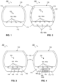
- the photoactivating device (100) as illustrated for instance in FIG. 1 comprises a body (110) disposed with a light source (160).
- the light source (160) is configured for emission of light for activation of the one or more photoactive components.
- the body (110) may have an overall rounded shape such a sphere, oval sphere, rounded cuboid; it assists with movement between laundry articles through the laundering space of the washing machine and amongst the laundry articles with reduced resistance.
- the exterior surface of the body (110) may be smooth to reduce friction; it may optionally be coated with a friction-reducing substance such as those containing polytetrafluoroethylene (PTFE) or Teflon.
- PTFE polytetrafluoroethylene
- the body (110) of the photoactivating device (100) may comprise a wall.
- the wall may be curved.
- the wall may be curved as to form a sphere, or oval sphere, or other rounded shape.
- the light source is disposed within the wall so as to emit light outwards from the wall.
- the body (110) of the photoactivating device (100) may comprise a base (112) and side wall (114) extending from the base (112), typically in an upwards direction.
- the base (112) may have a round or oval profile or a profile or another geometric shape.
- the base (112) may be essentially flat.
- the side wall (114) may be curved.
- the side wall (114) may be curved to as to form a dome or other rounded shape.
- the overall shape of the photoactivating device (100) may be spherical or oval ball; it assists with movement between laundry articles through the laundering space of the washing machine.
- the body (110) of the photoactivating device (100) may define a cavity (120).
- the cavity (120) may be empty.
- the cavity (120) may be provided with an inert substance (e.g. a polymeric material) to increase weight and/or alter a centre of gravity of the photoactivating device (100).
- the body (110) may be provided with one or more venting ports (118) to allow flooding and/or drainage of the cavity (120) with wash solvent (e.g . water) or with photoactive components in solution or suspension in the wash solvent.
- wash solvent e.g . water
- the body (110) may be provided with an opening (130) to the cavity (120) for passage, preferably by pouring therein, of the laundry treatment composition (see later below).
- the photoactivating device (100) is dimensioned to fit within the laundering space of the washing machine.
- the photoactivating device (100) is portable; it can be used in any washing machine.
- the photoactivating device (100) is autonomous.
- the body (110) may be formed from one or more polymeric material including, for instance, polypropylene, polycarbonate.
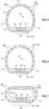
- the photoactivating device (100) as illustrated for instance in FIGs. 1 to 4 comprises a body (110) defining a cavity (120) for receiving the laundry treatment composition. It further comprises an opening (130) to the cavity (120).
- the opening (130) may be round or oval or other geometric shape.
- the laundry treatment composition may enter the cavity (120) through the opening (130).
- the opening (130) is configured for receiving, preferably by pouring therein, the laundry treatment composition. Through the same opening (130), the laundry treatment composition may exit the cavity (120) during the wash cycle.
- the opening (130) is configured for outward passage of the laundry treatment composition.
- the cavity (120) allows delivery of a dose of laundry treatment composition to the laundering space.
- the cavity (120) may be configured to retain the laundry treatment composition when the photoactivating device (100) rests on its base (112). By defining a volume of the cavity, the correct dose can be delivered to the laundering space.
- the cavity (120) may have a volume of 10 cm 3 to 300 cm 3 .
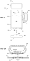
- the photoactivating device (100) as illustrated for instance in FIGs. 5 to 7 comprises a body (110) defining a cavity (120).
- the cavity (120) may be empty or provided with ballast ( e.g . FIGs. 6, 7) to allow the photoactivating device (100) to sink.
- the body may be provided with one or a plurality of venting ports (118) allowing the cavity to be flooded with wash solvent (e.g. water) which also provides ballast. Through the same venting port (118), wash solvent (e.g. water) may exit the cavity (120) during the wash cycle.
- the photoactivating device (100) may be devoid of an opening.
- the photoactivating device (100) is further provided with a light source (160) configured for emission of light for activation of the light-activating agent.
- the light source may comprise one or more light emitting diodes, LEDs.
- the LEDs are preferably heat resistant so as to withstand temperatures typically encountered in a wash cycle (e.g. 30 deg C to 90 deg C).
- the light source (160) may comprise a plurality of LEDs, wherein light emitted from all the LEDs in the plurality of the same wavelength range.
- the light source (160) may comprise a plurality of LEDs, wherein light emitted from at least 2 of the plurality is of a different wavelength range.
- the light source (160) may be disposed within the body (110) in the base (112) and/or side wall (114) of the photoactivating device (100), optionally within a void space (116, 122) therein.
- LEDs may be driven by multiplexing (fast sequential switching) in order to control intensities individually or in groups, and to reduce power consumption.
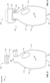
- the light source (160) may comprises a plurality of LEDs, wherein at least one (e.g. 1, 2 or more) of the plurality are internal emitters (160a) arranged to emit light into the cavity (120), as shown for instance in FIGs. 1 to 4 .
- the internal emitters (160a) may be disposed within the body (110) in the base (112) and/or side wall (114) of the photoactivating device (100), optionally within a void space (116, 122) therein.
- the internal emitters (160a) may be disposed in a region of the base (112), and/or in a region of the side wall (114).
- the internal emitters (160a) activate the one or more photoactive components contained in the cavity (120). They activate one or more photoactive components in solution or suspension with the laundering solvent (e.g . water) which momentarily enters the cavity (120) during the course of the wash cycle.
- Internal emitters (160a) may be distributed around the base (112) and/or side wall (114) at a density of at least 1 internal emitter (160a) per 2 cm 2 .
- the internal emitters (160a) may be provided when the body (110) is disposed with an opening (130) or venting port (118) thereby allowing activation of the one or more photoactive components in the laundry treatment composition while it is retained in the cavity (120) at least during initial stages of the wash cycle.
- the light source (160) may comprises a plurality of LEDs, wherein at least one ( e.g . 1, 2 or more) of the plurality are external emitters (160b) arranged to emit light into an exterior space e.g. outside the cavity (120), as shown for instance in FIGs. 2, 4 , 5 to 7.
- the external emitters (160b) may be disposed within the body (110) in the base (112) and/or side wall (114) of the photoactivating device (100), optionally within a void space (116, 122) therein.
- the external emitters (160b) may be disposed in a region of the base (112), and/or in a region of the side wall (114).
- the external emitters (160b) activate the one or more photoactive components in solution or suspension with the laundering solvent (e.g . water) during the course of the wash cycle.
- the external emitters (160b) may be distributed around the base (112) and/or side wall (114) at a density of at least 1 internal emitter (160a) per 2 cm 2 .
- All or a proportion of the external emitters (160b) may be disposed in a region of the body (110) known as a pre-treatment (PT) region (162), for instance in the base (112) as shown for instance in FIGs 4 to 7 .
- the PT region (162) may occupy ⁇ 50% of the outside surface of the photoactivating device (100).
- the external emitters (160b) in the PT region (162) allow activation by manual application of light to the one or more photoactive components when the laundry treatment composition has been applied directly the laundry article. Where a user wishes to pre-treat the laundry article, for instance, where the article is heavily stained, an aliquot of laundry treatment composition can be applied to the laundry article prior to laundering in the washing machine.
- the photoactivating device (100), in particular the PT region (162), can be swiped across the area of application, and light emitted by the external emitters (160b) illuminated in the PT region activates the one or more photoactive components.
- a motion sensing unit may detect a swiping motion of the photoactivating device (100) and temporarily activate the external emitters (160b) selectively in the PT region (162).
- the light source (160) may emit light at one wavelength range, or a two or more different wavelength ranges.
- the wavelength range may be selected based on the one or more photoactive components present in the laundry treatment composition.
- the light absorption profile of a photoactive component may at least partially overlap with the light emission profile of the light source.
- the wavelength range of the light source (160) may be in the visible, or UV range, or a combination of both.
- the wavelength range of the light source (160) may be selected from the spectrum range 250 nm to 750 nm.
- the wavelength range may correspond to ultraviolet (-350-380 nm), violet (-380-450 nm), blue (-450-495 nm), green (-495-570 nm), yellow (-570-590 nm), orange (-590-620 nm), or red (-620-750 nm) light.
- Table 1 below indicates exemplary emission ranges of the light source suited to activate various photoactive components.
- Table 1 Photoactive components and exemplary suited light source wave lengths Photoactive component Light source wavelength range Riboflavin 410 - 480 nm Phloxine B 500-600 nm Erythrosine 500-550 nm
- a wavelength range corresponding to UV (-350-400 nm), blue (400-495 nm) or red light (600-700 nm) is preferred.
- the photoactivating device (100) may be further provided with a motion sensing unit (170) configured to detect movements of the photoactivating device (100) in one or more degrees of freedom (DOF), as shown, for instance, in FIGs. 3 to 7 .
- the motion sensing unit (170) outputs signals responsive to the movements of the photoactivating device (100).
- the motion sensing unit (170) may detect rotational and/or displacement movements.
- the rotational movements may have 3DOF.
- the displacement movements may have 3DOF.
- the motion sensing unit (170) may comprise an accelerometer configured for detection of motion along at least 1 (1DOF), preferably 3 (3DOF) linear axis and/or around at least 1 (1DOF), preferably 3 (3DOF) rotational axis.
- the motion sensing unit (170) may comprise an orientation sensor (e.g. gyroscope, compass) configured for measurement of orientation or change of orientation of the photoactivating device (100).
- a gyroscope typically measures an angular rate of rotational movement about at least 1 (1DOF), preferably 3 (3DOF) rotational axis.
- the motion sensing unit (170) may comprise both an accelerometer and an orientation sensor.
- the motion sensing unit (170) may be attached in fixed (i.e. position and orientation) relation to the photoactivating device (100) or to the body (110) thereof.
- the motion sensing unit (170) may be disposed within the body (110) in the base (112) of the photoactivating device (100), optionally within a void space (116) therein.
- the motion sensing unit (170) may be disposed within the body (110) in the side wall (114) of the photoactivating device (100), optionally within a void space (122) therein.
- the motion sensing unit (170) may detect from movements of the photoactivating device (100), when the photoactivating device (100) is in a fixed position and/or orientation relative to a laundry article, optionally when the agitation unit is activated e.g . when the drum is revolving at the same time for instance during agitation or during a spin cycle.
- the motion sensing unit (170) can detect from movements of the photoactivating device (100), when a wash cycle has started and/or completed.
- the photoactivating device (100) may further comprise a controller (180) configured to control the light source (160) preferably responsive to signals received from the motion sensing unit (170), as shown, for instance, in FIGs. 3 to 7 .
- the controller (180) may be configured to control the light source (160) preferably responsive to a switch.
- the photoactivating device (100) may further comprise the controller (180) together with a switch and/or a motion sensing unit (170).
- the controller (180) typically comprises an electronic circuit.
- the electronic circuit may comprise a processor and memory.
- the light source (160) may control which LEDs are illuminated or extinguished, an intensity, an illumination pattern (e.g. steady or flashing) of a subset of the LEDs.
- the controller may be configured to drive the plurality of LEDs by multiplexing.
- the LEDs that are controlled by the controller (180) may be external emitters (160a) and/or external emitters (160b).
- the controller (180) may selectively control the external emitters (160b) disposed in the pre-treatment region.
- the controller (180) may be configured to control the light source (160) responsive to a switch.
- the switch may be a momentary contact switch or a maintained switch.
- the controller (180) may be configured to turn the light source on or off in response to the switch.
- the controller (180) may be configured to control the light source according to a sequence of pre-set time periods corresponding to a wash cycle, that is initiated by the switch. In one example, the controller may illumine the light source (160) 10 minutes after the switch has been activated, maintain illumination for a duration of the active wash cycle (e.g. 90 to 120 minutes), then extinguish the light source (160).
- a duration of the active wash cycle e.g. 90 to 120 minutes
- the controller (180) may be configured to control the light source (160) responsive to a switch and/or a motion sensing unit (170).
- the controller (180) may be configured to detect from the signals from the motion sensing unit (170) a start and/or completion of a wash cycle of the washing machine.
- the controller (180) may be configured to control light emitted by the light source (160) when signals of the motion sensing unit (170) correspond to a start, duration or end of the wash cycle.
- the LEDs that are controlled by the controller (180) may be external emitters (160a) and/or external emitters (160b).
- the controller (180) may be configured to:
- the light emission reduction or the low (L) setting may correspond to an overall dimming and/or, an overall extinguishing of emitted light, and/or a light source emission level that is lower than the normal (N) setting.
- the dimming may be achieved by reducing voltage (steady or within a time period) supplied to the light source, or extinguishing one or more LEDs thereby achieving an overall dimming effect.
- the LEDs that contribute to the light emission decrease or low (L) setting may be external emitters (160a) and/or external emitters (160b).
- the photoactivating device (100) may emits insufficient light to active the one or more photoactive components in the laundry treatment composition present in the cavity (120) and/or in the washing solvent (e.g . water).
- the light emission increase or normal (N) setting may correspond to an overall increase of emitted light, and/or a pre-defined light source emission level that is higher than the low (L) setting.
- the photoactivating device can active the one or more photoactive components in the laundry treatment composition present in the cavity (120) and/or in the washing solvent ( e.g . water).
- the increase may be achieved by increasing voltage supplied (steady or within a time period) to the light source, or re-illuminating one or more LEDs thereby achieving an overall more light emission.
- the LEDs that contribute to the light emission increase or normal (N) setting may be external emitters (160a) and/or external emitters (160b).
- the photoactivating device (100) may emit sufficient light to activate the one or more photoactive components in the laundry treatment composition present in the cavity (120) and/or in the washing solvent ( e.g . water).
- the normal (N) setting may have different intensities depending on the extent of motion determined from signals received from the motion sensing unit (170). For instance N1 may be a maximum intensity during agitation (A), while N2 may a lower intensity but still more intense than emission in a (L) setting; the N2 setting may be applied during rest (R).
- the controller (180) may be configured to control the light source (160) responsive to signals received from the motion sensing unit (170) that are indicative of an active wash cycle and a fixed position and/or orientation (linear and angular) of the photoactivating device (100) relative to one or more laundry articles in the washing machine during an active wash cycle.
- the controller (180) is configured to reduce light emitted by the light source (160), or set the light emitted by the light source (160) to a low (L) setting in such case.
- light emission may be at a constant intensity, or may increase or decrease depending on a phase of the wash cycle or upon a fixed positional/rotational relation of the photoactivating device with a laundry article (see later below).
- the controller may be configured to set the light emitted by the light source (160) to a low (L) or normal (N) setting depending on the movement of the photoactivating device (100) indicated by the signals of the motion sensing unit (170).
- the controller (180) may be configured to reduce light emitted by the light source (160) or set the light emitted by the light source (160) to a low (L) setting when signals of the motion sensing unit (170) correspond to a period (e.g. period t rest ) of non-activation of the agitation unit, for instance, when the washing drum, paddle, or agitation is static during an active wash cycle.
- the controller (180) may be configured to increase light emitted by the light source (160) or set the light emitted by the light source (160) to a normal (N) setting when signals of the motion sensing unit (170) correspond to a period (e.g. period t agitation ) of activation of the agitation unit, for instance, when the washing drum, paddle, or agitation is active during an active wash cycle.
- a period e.g. period t agitation
- the photoactivating device (100) is suitable for a wash cycle of any degree of mechanical agitation, where the period of rest and agitation are not known. The release of photoactivated products is more slow, allowing other agents in the laundry treatment composition to have an effect prior to or during activation.
- the controller may be configured to prevent or reduce local overbleaching of a laundry article when the photoactivating device (100) is positionally and/or rotationally fixed with relative to one or more laundry articles in the washing machine during an active wash cycle.
- the LEDs that are controlled by the controller (180) may be external emitters (160a) and/or external emitters (160b).
- the controller (180) may be configured to reduce light emitted by the light source (160) or set the light emitted by the light source (160) to a low (L) setting when signals of the motion sensing unit (170) correspond to the washing machine spin cycle.
- the controller (180) may be configured to reduce light emitted by the light source (160) or set the light emitted by the light source (160) to a low (L) setting when signals of the motion sensing unit (170) correspond to an entanglement of the photoactivating device with one or more laundry articles during an active wash cycle.
- the controller (180) may be configured to increase light emitted by the light source (160) or set the light emitted by the light source (160) to a normal (N) setting when signals of the motion sensing unit (170) correspond to a start of a washing cycle.
- Detection of the wash cycle start assists with power management, primarily to extend power source life.
- a washing machine is programmed to commence a cycle with a delay for instance during the night, automatic detection of the wash cycle start extends power source life. It further defers activation of the one or more photoactive components in the laundry treatment composition until after the cycle has begun, thereby timing release of light-activated products to coincide with agitation of the laundry articles in laundering solvent (e.g . water) when it will have an optimum effect.
- solvent e.g . water
- the controller (180) may be configured to reduce light emitted by the light source (160) or set the light emitted by the light source (160) to a low (L) setting, or switch off the light source when signals of the motion sensing unit (170) correspond to a completion of a washing cycle.
- the controller (180) may be configured to determine from signals received from the motion sensing unit (170) an operation mode (652) which is selected from wake (656) and sleep (654, 658) - see for instance FIG. 13 .
- sleep (654, 658) mode the photoactivating device (100) is typically not in use and no motion is detected.
- Light emission may cease or be switched off (682, 698).
- One or more sensors may be switched off to reduce power consumption.
- Sleep mode assists with power management, primarily to extend power source life. In particular when a washing machine is not emptied for a number of hours, switching to a sleep mode end extends power source life. Sleep mode may be activated by detection of little or no movement for a duration of time e.g.
- the operation mode may switch from sleep (654, 658) to wake (656), when the active sensors in the motion sensing unit (170) detect movement. In wake mode, more or all the motion sensors in the motion sensing unit (170) become active. In wake mode (656), the controller may be configured to determine from the motion sensing unit (170) an activity mode (660) and/or a photoactivating device status (666).
- the controller (180) may be configured to determine from signals received from the motion sensing unit (170) an activity mode (660) which may be selected from swipe (662) and active wash cycle, AWC (664) - see for instance FIG. 13 .
- the activity mode (660) is set to swipe (662) when the controller (180) determines from the motion sensing unit (170) that the photoactivating device is being swiped across a laundry article in a sweeping motion in order to pre-treat a stain with an aliquot of laundering treatment agent by the user.
- the controller (180) activates (684) the light source (160), in particular the external emitters (160b) in the PT region when in the swipe (662) activity mode (660).
- the internal emitters (160a) and/or external emitters (160b) outside the PT region may or may not be activated.
- the controller (180) may maintain the swipe (662) activity mode (660) for a duration of the sweeping motion, optionally for an additional period t swipe .
- the activity mode (660) may be set to AWC (664) (active wash cycle) when the controller (180) determines from the motion sensing unit (170) that the photoactivating device (100) is disposed within a laundering space and a washing cycle is active.
- the activity mode (660) is set to AWC (664) when the controller (180) determines from the motion sensing unit (170) that the photoactivating device is being moved (displaced and/or rotated) in space, consistent with a phase of a wash cycle.
- the controller (180) activates and regulates the light source (160) when in the AWC (664) activity mode (660) - see FIG. 8 868-696. Regulation of the light source (160) may be determined by the photoactivating device, PD, status (666) described below.
- Both internal emitter (160a) and external emitters (160b) may be activated. Both internal emitters (160a) and external emitters (160b) may be activated. Both internal emitters (160a) and external emitters (160b) except in the PT region may be activated. Only internal emitters (160a) may be activated.
- the controller (180) may maintain the AWC (664) activity mode (660) for a duration of the tumbling motion, optionally for an addition period t AWC . In the AWC (664) activity mode (660), the controller may be configured to determine from the motion sensing unit (170) a photoactivating device status (666).
- the controller (180) may be configured to determine from signals received from the motion sensing unit (170) a photoactivating device, PD, status (666) which may be selected from motion (M) or fixed (F) with respect to the laundry article.
- the PD status (666) may be activity mode (660) may be determined when in AWC (664) (active wash cycle) activity mode (660).
- AWC active wash cycle
- the photoactivating device (100) is determined to be moving e.g. rotation and/or travelling relative to a laundry article.
- M motion PD status
- Typically (M) motion PD status (666) arises during agitation (A), and sometimes an initial phase of a rest (R) period of an active wash cycle (613).
- a fixed (F) PD status (666) the photoactivating device (100) is determined to be not moving e.g . rotationally and positionally fixed relative to a laundry article.
- fixed (F) PD status (666) arises when the photoactivating device (100) is entangled by one or more laundry articles, and/or, when the washing machine is within a spin cycle (S).
- the controller (180) may be configured to control the light source (160) responsive to the fixed (F) or motion (M) PD status (666).
- the controller (180) is configured to set light emitted by the light source (160) in the fixed (F) PD status (666) to the low (L) setting.
- the light source (160) that is controlled by the controller (180) may be external emitters (160a) and/or external emitters (160b).
- the controller (180) is configured to set light emitted by the light source (160) in the motion (M) PD status (666) to a normal (N) setting.Movement of the photoactivating device (100) (100) within the laundering space of the washing machine maximises a slow-release of the products of the photoactivation.
- a slow release has is advantageous because a lifespan of a photoactivation product is short, and other washing processes such as agitation, enzymatic degradation, dissolution can take an effect during or before the photoactivation product.
- FIG. 13 sets out mechanical movements of the photoactivating device (100) (100) (box 630) corresponding to a user pre-treatment or to a washing machine cycle (box 610), corresponding exemplary modes and statuses set by the controller (170) (box 650) responsive to signals of the sensor unit (170), and a corresponding exemplary activity of the light source (160) (box 680).
- the washing machine prior to a wash has an off status (612), and there is no activity.
- the off status is typically between washes or when the washing machine is set on a timer.
- an active wash cycle (613)
- the drum, paddle, agitator, etc are actuated and the laundry articles are induced to move.
- the active wash cycle (613) starts with a pre-wash cycle (614, 616) comprising agitation (A) and rest (R) phases (614), followed by a spin cycle (S) (616).
- a longer main wash cycle (618, 620) comprising agitation (A) and rest (R) phases (618), followed by a spin cycle (S) (620).
- a rinse cycle (620, 622) comprising agitation (A) and rest (R) phases (620), followed by a spin cycle (S) (622).
- S spin cycle
- the photoactivating device (100) is not moved for a period and has an inactivity status (632).
- the inactivity status is typically when the photoactivating device (100) is stored or when the washing machine is set on a timer and the photoactivating device (100) is within the laundering space without activity.
- the user may manually pre-treat a stain on a laundry article by applying an aliquot of laundry treatment composition directly thereon, and swiping (634) the photoactivating device (100) across the stain in order to activate the light source (160, 160b) in the pre-treatment region and the one or more photoactive components within the laundry treatment composition.
- movements of the photoactivating device (100) may be classified as motion (m) or fixed (f) with respect to the laundry article.
- motion (m) the photoactivating device (100) is moving e.g. rotation and/or travelling relative to a laundry article.
- the photoactivating device (100) moves during an agitation (A) phase of the wash cycle, and sometimes during an initial phase of a rest (R) period of an active wash cycle (613).
- a fixed motion (f) the photoactivating device is not moving e.g . rotationally and positionally fixed relative to a laundry article. Movements of the photoactivating device (100) in box 630 correspond with phases of an active wash cycle in box 610.
- the movement of the photoactivating device (100) may be classified as motion (m) or fixed (f) (636) during the (A)/(R) stage (614) of the wash cycle, and fixed (f) (638) during the spin cycle (616).
- the movement of the photoactivating device (100) may be classified as motion (m) or fixed (f) (640) during the (A)/(R) stage (618) of the wash cycle, and fixed (f) (642) during the spin cycle (616).
- the movement of the photoactivating device (100) may be classified as motion (m) or fixed (f) (644) during the (A)/(R) stage (620) of the wash cycle, and fixed (f) (646) during the spin cycle (622).
- controller (180) may set different modes and status (e.g. operation mode (652), activity mode (660), photoactivating device (PD) status (666) responsive to signals received from the sensor unit (170).
- modes and status e.g. operation mode (652), activity mode (660), photoactivating device (PD) status (666) responsive to signals received from the sensor unit (170).
- the operation mode (652) may be set to sleep (654, 658) corresponding to inactivity (632, 648) in box 630 of the photoactivating device (100), which may consume less power as mentioned elsewhere herein.
- the operation mode 652 may be set to wake (656) corresponding to swiping (634) or periods of motion and fixed movement (634 - 646) in box 630 of the photoactivating device (100), where the photoactivating device (100) consumes more energy, and the controller (170) determines from the sensor signals movements (e.g. (m), (f)) of the photoactivating device (100).
- the activity mode (660) may be set to swipe (662) corresponding a swiping action (634) in box 630 of the photoactivating device (100), which may selectively illuminate the external emitters (160b) in the pre-treatment region for a duration of the swiping motion, optionally for an additional period t swipe .
- the activity mode (660) may be set to AWC (664) (active wash cycle) corresponding movements of the photoactivating device (100) that may be classified as motion (m) or fixed (f) (636 to 646) in box 630, also corresponding to an active wash cycle of the washing machine in box 610.
- the photoactivating device (PD) status (666) may be set to motion (M) or fixed (F) corresponding to movements of the photoactivating device (100) during an active wash cycle (613) that are classified as motion (m) or fixed (f) with respect to the laundry article in box 630.
- the PD status (666) may be set to (M) or (F) (668 to 678) corresponding movements of the photoactivating device (100) that may be classified as motion (m) or fixed (f) (636 to 646) in box 630, also corresponding to phases (614-622) of an active wash cycle of the washing machine in box 610.
- the light source (160) in box 680 may be set to off (682, 698) corresponding to inactivity (632, 648) in box 630 of the photoactivating device (100), and a sleep (654, 658) operation mode (652) in box 650.
- the light source (160) in box 680 in particular external emitters (160b) in the PT region ( e.g. base) may be illuminated (684) corresponding to a swipe (662) activity mode (660) in box 650, and a swipe motion (634) of the photoactivating device in box 630.
- the light source (160) in box 680 may be set to different intensity levels - normal (N1, N2), and low (L) (686 to 696) responsive to a (M) or (F) PD status (666) during the active wash cycle.
- the light source (160) is predominantly at a normal (N1, N2) level, and corresponding to a (M) PD status (668).
- the normal level is shown as having a higher (N1) and lower (N2) level, the N1 level being more intense and selected where movement of the photoactivating device (100) is greater than in N2, but both still within the category of (M).
- the light source (160) is momentarily at a low (L) level corresponding a (F) PD status (668), where the photoactivating device (100) has stopped moving in relation to a laundry article or has become entangled.
- the light source (160) is predominantly at a low (L) level, and corresponding to a (F) PD status (670).
- the photoactivating device (100) stops moving in relation to a laundry article during a spin cycle.
- the light source (160) is predominantly at the normal (N1, N2) level, and corresponding to a (M) DD status (672).
- the light source (160) is momentarily at a low (L) level corresponding a (F) PD status (674), where the photoactivating device (100) has stopped moving in relation to a laundry article or has become entangled.
- the main-wash cycle (692) corresponding to spin (S) cycle of the washing machine status (620)
- the light source (160) is predominantly at a low (L) level, and corresponding to a (F) PD status (674).
- the light source (160) is predominantly at the normal (N1, N2) level, and corresponding to a (M) PD status (676).
- the light source (160) is momentarily at a low (L) level corresponding a (F) PD status (676), where the photoactivating device (100) has stopped moving in relation to a laundry article or has become entangled.
- the rinse cycle (696) corresponding to spin (S) cycle of the washing machine status (622
- the light source (160) is predominantly at a low (L) level, and corresponding to a (F) PD status (678).
- the motion sensing unit (170), or in particular the controller (180) may be configured for detection of motion within the washing machine.
- the motion may be a movement of the washing machine agitation unit configured to induce movement of the laundry article (e.g. rotation of the drum) and/or of the washing solvent, which implies a centrifugal acceleration and/or an angular acceleration, and the photoactivating device (100) would experience a measureable centrifugal acceleration and/or a tangential acceleration as a result.
- Detection of motion may be determined from measurement of centrifugal acceleration by the motion sensing unit (170) or in particular the controller (180).
- the photoactivating device (100) When the washing machine drum rotates, the photoactivating device (100) would adopt a similar motion depending on the centrifugal forces.
- Centrifugal acceleration (m/s 2 ) expected to be experienced by the photoactivating device (100) can be determined from the equation ⁇ ⁇ ⁇ r , where ⁇ is the angular velocity in rad/sec and r the washing machine drum radius in metres.
- the centrifugal acceleration (m/s 2 ) can be approximately expressed as (rpm/10) 2 x r, where rpm are revolutions per minute of the washing machine drum.
- angular velocities of washing machine drums during agitation are in the 10 - 80 rpm (revolutions per minute) range
- angular velocities may be equal to or exceed 100 rpm during other phases of a wash cycle, for example in a spin cycle they are equal to or exceed 200 rpm ( e.g. 500 rpm, 800 rpm, 1000 rpm or more).
- a washing drum machine radius r ranges from about 0.2 m to about 0.4 m, or greater.
- Detection of centrifugal acceleration may be used to determine an activity mode of the washing machine, for instance, an active wash cycle (AWC), and the phases within the wash cycle such as agitation (low speed drum rotations 10 - 80 rpm), higher speed drum rotations (100 rpm upwards) and spin cycle (200 rpm upwards). It can also be used to determine when the photoactivating device (100) is moving in synchronisation with the drum ( i.e. is maintained at a fixed position with respect to a point on the drum) (e.g. 100 rpm upwards).
- AWC active wash cycle
- the controller (180) may be configured to identify from the centrifugal acceleration an active wash cycle (AWC, see later below).
- the motion sensing unit (170) or in particular the controller (180) may be configured for measurement of centrifugal acceleration, for instance, equal to or greater than 0.2m/s 2 (drum of radius 0.2 m rotating at 10 rpm), which is indicative of an active wash cycle.
- the controller (180) may be configured to identify from the centrifugal acceleration an agitation phase (low speed drum rotation) of active wash cycle.
- the motion sensing unit (170) or in particular the controller (180) may be configured for measurement of centrifugal acceleration, for instance, in a range 0.2m/s 2 to 26 m/ 2 (drum of radius 0.2 to 0.4 m rotating at 10 to 80 rpm), which is indicative of agitation phase (low speed drum rotation) of an active wash cycle.
- the controller may be configured to set the light source (160) to normal (N) in such condition to activate the one or more photoactive components in the treatment composition.
- the controller (180) may be configured to determine from a (non-zero) constant centrifugal acceleration that the photoactivating device (100) is moving in synchronisation with the drum.
- the constant centrifugal acceleration may be observed for a certain duration (e.g. at least 10 seconds). This would imply being trapped or entangled against an article of clothing especially during higher speed drum rotations ( e.g. 100 rpm or more, corresponding to a centrifugal acceleration of, for instance, at least 20 m/s 2 for a drum of radius 0.2 m rotating at 100 rpm) where centrifugal forces are applied.
- the photoactivating device (100) is centrifuged towards the outer part of the drum and stays in prolonged contact with specific parts of a laundry articles without being able to move, due to the high centrifugal force exerted in those conditions. Under these conditions, there may be a local bleaching of the laundry articles where the photoactivating device (100) continuously emits photoactivating light to the same region of laundry article. Accordingly, controller may be configured to set the light source (160) to low (L) level (see below) to avoid local damage to the laundry articles.
- the controller (180) may be configured to identify from the centrifugal acceleration a spin cycle of active wash cycle.
- the motion sensing unit (170) or in particular the controller (180) may be configured for measurement of centrifugal acceleration, for instance, of at least 80 m/sec 2 (drum of radius 0.2 m rotating at 200 rpm or higher), which is indicative of a spin cycle of an active wash cycle.
- the photoactivating device (100) is centrifuged towards the outer part of the drum and stays in prolonged contact with a specific parts of a laundry articles without being able to move, due to the high centrifugal force exerted in those conditions.
- controller may be configured to set the light source (160) to low (L) level (see below) to avoid local damage to the laundry articles.
- the controller may be configured to set the light source (160) to low (L) level (see below) in such condition to prevent local avoid local damage to the laundry articles.
- Detection of motion may in addition or alternatively be determined from measurement of linear acceleration by the motion sensing unit (170) or in particular the controller (180).
- the controller (180) may be configured to identify from the linear acceleration an active wash cycle.
- the motion sensing unit (170) or in particular the controller (180) may be configured for measurement of linear acceleration, for instance, equal to or greater than of at least 0.1-0.2 m/sec 2 , which is indicative of an active wash cycle.
- the controller (180) may be configured to identify from the linear acceleration an agitation phase (low speed drum rotation) of active wash cycle.
- the motion sensing unit (170) or in particular the controller (180) may be configured for measurement of linear acceleration, for instance, of at least 0.1-0.2 m/sec 2 , which is indicative of agitation phase ( i.e. entering into a low speed drum rotation) of an active wash cycle.
- the controller (180) may be configured to determine from a linear velocity change, i.e. a linear acceleration and when the linear acceleration remains constant for a certain duration (e.g . 10-20 seconds or longer) that the photoactivating device (100) is entering into a phase where it will be moving in synchronisation with the drum. This would imply being trapped or entangled against an article of clothing especially during higher speed drum rotations ( e.g . 100 rpm or more) where centrifugal forces are applied.
- the photoactivating device (100) is centrifuged towards the outer part of the drum and stays in prolonged contact with specific parts of a laundry articles without being able to move, due to the high centrifugal force exerted in those conditions.
- controller may be configured to set the light source (160) to low (L) level (see below) to avoid local damage to the laundry articles.
- the motion sensing unit (170) may comprise an orientation sensor and/or an accelerometer.
- the controller (180) is configured to set the light source (160) to a low (L) setting when the motion sensing unit (170) detects a rate of orientation change or angular velocity that exceeds 100 rpm, which corresponds a synchronized movement of the photoactivating device (100) and drum, where the photoactivating device (100) will stay in contact with a specific fabric without being able to move, due to the high centrifugal force exerted in those conditions.
- the photoactivating device (100) may further comprise a power source (190).
- the power source (190) provides electrical power to the light source (160) and to the controller (180) and motion sensing unit (170).
- the power source (190) may comprise a non-rechargeable, battery, a rechargeable battery, a capacitor, an inductive coil, or a dynamo.
- a rechargeable battery may be rechargeable by induction.
- the power source (190) may be positioned such that a weight centre of gravity of the photoactivating device (100) corresponds to a geometric centre of gravity of the photoactivating device (100). This allows even tumbling for distribution laundry treatment composition and light activation.
- the laundry articles are items normally washable in a washing machine. They include garments, and other fabric items including curtains, towelling, bedding, handkerchiefs, furniture covers, and the like.
- the photoactivating device (100) may be provided with immobilised titanium dioxide.
- the immobilised titanium dioxide may be coated onto a surface of the photoactivating device (100) and/or provided on a support such as a filter. At least a part of the body (110) of the photoactivating device (100) may be coated with titanium dioxide.
- the immobilised titanium dioxide is located so as to receive light emitted by the light source (160).
- the immobilised titanium dioxide may be provided on a cavity (120) wall.
- the immobilised titanium dioxide may be provided on an exterior wall.
- the immobilised titanium dioxide may have a specific surface area between about 50 m 2 /g to about 400 m 2 /g.
- the bulk density of the immobilised titanium dioxide may be between about 100 g/l to about 800 g/l.
- the titanium dioxide may be a carbon modified titanium dioxide having a carbon content of between about 0.01% by weight to about 5% by weight.
- Titanium dioxide can also perform as a photo-bleaching agent when radiated with radiation having wavelength between about 10 nm and about 1200 nm. Radiation in the ultraviolet spectrum may be less attractive due to potential human exposure issues.
- immobilised titanium dioxide when photoactivated bleaches dyes present in the washing solvent. It may prevent that dyes in the washing solvent from one darker coloured laundry article are deposited on a lighter coloured laundry article. In other words it bleaches and neutralises 'fugitive dyes'.
- the laundry treatment composition also known as treatment composition herein may be formulated as a powder, liquid, suspension, emulsion suspension, tablet, pouch or other form.
- the treatment composition may be flowable, meaning that it is pourable from the container (510) and/or from the photoactivating device (100) where it is provided with an opening (130).
- the treatment composition is for the treatment of laundry articles within a washing machine.
- the laundry treatment composition may be a laundry detergent or a fabric enhancer.
- the treatment composition comprises one or more photoactive components.
- a photoactive component is one that reacts chemically to light.
- One of the photoactive components may be a photoactive bleaching agent.
- the laundry treatment composition may comprise other components including, but not limited to, surfactants, perfumes, stabilizers, builders, bleaching agents, disinfectants, enzymes, graying inhibitors, brighteners, and the like.
- the treatment composition may comprise one or more photoactive components, at least one of which may be a photoactive bleaching agent.
- the treatment composition may comprise the photoactive bleaching agent, or mixtures of different photoactive bleaching agents, in a quantity such that, when the treatment composition is dissolved in the washing solvent at the recommended dosage, it will provide a photoactive bleaching agent concentration in the washing solvent between 0.005 ppm and 50 ppm, preferably between 0.01 ppm and 10 ppm, more preferably between 0.05 ppm and 5 ppm, most preferably between 0.1 ppm and 1 ppm.
- the photoactive bleaching agent may be any suitable for bleaching laundry articles such as riboflavin, phloxine B, and erythrosine, or salts thereof.
- a suitable photoactive bleaching agent may be riboflavin. Radiation with wavelength in the range 400 nm and 500 nm, or in the near UV range between 320 nm and 400 nm can activate the riboflavin for the purposes of photo-bleaching.
- the treatment composition may comprise riboflavin in a quantity ranging from about 1 % to about 0.001% by weight of the treatment composition.
- a suitable photoactive bleaching agent may be phloxine B. Radiation with wavelength in the range between about 500 nm and 580 nm can activate the phloxine B for the purposes of photo-bleaching.
- the treatment composition may comprise phloxine B in a quantity ranging from about 1% to about 0.001% by weight of the treatment composition.
- a suitable photoactive bleaching agent may be erythrosine. Radiation with wavelength in the range between about 450 nm and 550 nm can activate the erythrosine for the purposes of photo-bleaching.
- the treatment composition may comprise erythrosine in a quantity ranging from about 1% to about 0.001% by weight of the treatment composition
- the container unit (500) is configured for stable storage of the laundry treatment composition. It may be configured for dispensing the laundry treatment composition, preferably by pouring, using a pump dispenser, or via a tap. It may be configured for removal of the laundry treatment composition dose where it is formulated as a tablet or pouch.
- the container unit (500) may be refillable or disposable after a single use.
- the container unit (500) comprises a container (510) and a closure (e.g. cap (540), lid (542)) for sealing or closing the container.
- the closure may be repeateably closable.
- the container (510) comprises a container body (516), defining a storage volume (520) for holding a plurality of doses of the laundry treatment composition (522).
- the laundry treatment composition may be formulated as a liquid or gel, for instance, in the example of FIGs. 8 to 11 .
- the laundry treatment composition may be formulated as a powder, tablet or pouch doses, for instance, in the example of FIG. 12 .
- the container (510) typically has a base end (502) and a top end (504). Disposed at the base end (520) is a base (512) configured to stably support the container (510) in an upright position when resting on the base (512). Extending from the base (512) is a side wall (514). The top end (504) is typically provided an opening (530) for pouring out or removal of the laundry treatment composition.
- the side wall (514) narrows towards the top end to form the opening (530).
- the side wall (514) may narrow towards the top end to form a neck (532), optionally threaded (534), around the opening (530).
- the side wall (514) remains straight to form a wide opening (530) to allow manual access to the storage volume (520).
- a carrying or pouring handle (518) may be integrated into the container body (516). Tilting of the container (510) allows a liquid or powered treatment composition to be poured from the opening (530).
- the container unit (500) may further comprises a repeabable closure (540, 542) for sealing or closing the container (510) opening (530).
- the repeatable closure may comprise a threaded cap (540), as shown, for instance, in FIGs. 8 to 11 .
- a thread (544) on the inside of the cap (540) may co-operate with a thread (534) on the outside of the container (510) neck (532), thereby sealing the container (510) storage volume (520) when the cap is tightened by rotation over the thread, and unsealing the container (510) when the cap is loosened by rotation in an opposing direction over the thread.
- the repeatable closure may comprise a lid (542), as shown, for instance, in FIG. 12 .
- a rim of the lid cooperates with a rim of the opening allowing the storage volume (520) to be closed.
- the container unit (500) may further comprise a coupling element (115, 117, 538, 539) for repeatable dismountable attachment of the photoactivating device (100) to the container unit (500).
- the coupling element may be integrated onto the threaded cap (540), for instance as a protrusion (538) onto which the photoactivating device (100) opening (130) engages and latches over (see for example FIG. 9 ), and a stop member (539) configured to prevent advancement of the photoactivating device (100) beyond the cap (540).
- the coupling element may be comprised in a projection (115) of the container (510) side wall (514), as shown, for instance in FIGs. 10 and 11 .
- the coupling element preferably cooperates with the body (110) of the photoactivating device (100) around its opening (130).
- the coupling type may be push-fit, threaded and/or magnetic.
- the coupling element may be comprised in a region (117) of the container (510) side wall (514) that is magnetic by utilising one or more permanent magnets (588), as shown, for instance in FIGs. 12 and 12A .
- the container unit (500) may be disposed with an induction coil (594), configured for inductively charging a rechargeable battery of the photoactivating device (100), as shown, for instance, in FIGs. 11 , 12 and 12A .
- the induction coil (594) may be connected to a charging controller (590) that is connected to a container power source (592) as shown, for instance, in FIG. 11 .
- the charging controller is configured to regulate the flow of current from a power source to the induction coils.
- the power source may be a container power source (592) comprising a battery, rechargeable or non-rechargeable.
- the container power source (592) may be integrated in the container. Examples of suitable non-rechargeable battery types include lithium and alkaline batteries.
- the container power source (592) and charging controller (590) may be disposed in a cavity within the base of the container (510).
- the power source may be a mains-powered electrical adapter.
- the induction coil (594) may be connected to electrical contacts (584) in the base (512) of the container (510) that co-operate with complementary electrical contacts (582) disposed in a docking station (580) as shown, for instance, in FIG. 12 .
- the container base (512) can dismountably rest on the docking station (580).
- electrical power from the docking station connected to a power source such as a mains-powered electrical adapter, supplies electrical power via the contacts (582, 584) to the induction coils (594).
- An optional regulator (586) may be control the supply of power to the induction coil (594)
- the induction coil (594) may be disposed operatively with respect to the coupling element (115, 117, 538), and is configured for charging the photoactivating device (100) attached to the coupling element.
- the photoactivating device (100) may be provided with a complementary induction coil (196) that receives inductively current from the induction coil (594) of the container unit (500); charging current is conducted along a cable (194) to a charging regulator (192) that is connected to the power source (190) that is a rechargeable battery in the photoactivating device (100).
- the container unit (500) may be made substantially from one or more opaque materials. Examples of suitable material include, but are not limited to, polyethylene, polypropylene, metal, or other material.
- the container unit (500) may be opaque to electromagnetic radiation in the wavelength region between about 2 nm and about 1200 nm, or even between about 380 nm to about 800 nm By opaque, it is meant that transmittance is reduced by more than about 80%, or more than about 90%, or more than about 95%, or more than about 99%, as compared to complete radiation transmission.
- kits comprising a photoactivating device (100) and a container unit (500) as described herein.
- kits comprising a photoactivating device (100) as described herein and a laundry treatment composition as described herein.
- a method, not forming part of the present invention, of laundering laundry articles comprises the steps:
- the method may further a comprise a step or reducing light emitted by the light source (160) or setting the light emitted by the light source (160) to a low (L) setting when signals of the motion sensing unit (170) correspond to an entanglement of the photoactivating device with one or more laundry articles or to a washing machine spin cycle during an active wash cycle.
- the method may further a comprise a step of pre-treatment of an laundry article comprising;
Landscapes
- Chemical & Material Sciences (AREA)
- Engineering & Computer Science (AREA)
- Wood Science & Technology (AREA)
- Life Sciences & Earth Sciences (AREA)
- Chemical Kinetics & Catalysis (AREA)
- Oil, Petroleum & Natural Gas (AREA)
- Organic Chemistry (AREA)
- Mechanical Engineering (AREA)
- Textile Engineering (AREA)
- Health & Medical Sciences (AREA)
- Emergency Medicine (AREA)
- Accessory Of Washing/Drying Machine, Commercial Washing/Drying Machine, Other Washing/Drying Machine (AREA)
- Control Of Washing Machine And Dryer (AREA)
- Photographic Processing Devices Using Wet Methods (AREA)
- Control Of Velocity Or Acceleration (AREA)
Claims (8)
- Photoaktivierungsvorrichtung (100) für den Einsatz in einer Waschmaschine zum Aktivieren einer oder mehrerer photoaktiver Komponenten in einer Wäschebehandlungszusammensetzung, umfassend:- eine Lichtquelle (160), die zum Aussenden von Licht zur Aktivierung der einen oder der mehreren photoaktiven Komponenten konfiguriert ist,- einen Regler (180); und- eine Bewegungserfassungseinheit (170), wobei der Regler (180) dazu konfiguriert ist, die Lichtquelle (160) als Reaktion auf die von der Bewegungserfassungseinheit (170) empfangenen Signale zu regeln, und- wobei optional die Photoaktivierungsvorrichtung (100) ferner umfasst:- einen Körper (110), der einen Hohlraum (120) zum Aufnehmen und Halten der Wäschebehandlungszusammensetzung definiert, und- eine Öffnung (130) zu dem Hohlraum (120), die zum Aufnehmen der Wäschebehandlungszusammensetzung konfiguriert ist;dadurch gekennzeichnet, dass der Regler (180) dazu konfiguriert ist, Licht zu reduzieren, das von der Lichtquelle (160) emittiert wird, wenn Signale der Bewegungserfassungseinheit (170) Folgendem entsprechen:- einem Schleuderzyklus der Waschmaschine, wobei optional eine durch die Bewegungserfassungseinheit (170) gemessene Zentrifugalbeschleunigung mindestens 80 m/s2 beträgt.
- Photoaktivierungsvorrichtung (100) nach einem von Anspruch 1, wobei der Regler (180) dazu konfiguriert ist, Licht zu reduzieren, das von der Lichtquelle (160) emittiert wird, wenn Signale der Bewegungserfassungseinheit (170) einem Zeitraum der Nichtaktivierung einer Waschmaschinenbewegungseinheit entsprechen, die dazu konfiguriert ist, eine Bewegung der Wäschestücke zu induzieren.
- Photoaktivierungsvorrichtung (100) nach einem der Ansprüche 1 bis 2, wobei die Bewegungserfassungseinheit (170) einen oder mehrere Beschleunigungsmesser und/oder einen oder mehrere Orientierungssensoren umfasst.
- Photoaktivierungsvorrichtung (100) nach einem der Ansprüche 1 bis 3, umfassend den Hohlraum (120) zum Aufnehmen und Halten der Wäschebehandlungszusammensetzung, wobei die Lichtquelle (160) eine Vielzahl von Leuchtdioden, LEDs, umfasst, wobei mindestens einige der LEDs interne Emitter (160a) sind, die dazu angeordnet sind, Licht in den Hohlraum zu emittieren (120).
- Photoaktivierungsvorrichtung (100) nach einem der Ansprüche 1 bis 4, wobei die Lichtquelle (160) eine Vielzahl von Leuchtdioden, LEDs, umfasst, wobei mindestens einige der LEDs externe Emitter (160b) sind, die dazu angeordnet sind, Licht in einen Außenraum zu emittieren.
- Photoaktivierungsvorrichtung (100) nach Anspruch 5, wobei mindestens einer der externen Emitter (160b) in einem Bereich, einem PT-Bereich (162), der ≤ 50 % der Außenoberfläche der Photoaktivierungsvorrichtung (100) belegt, optional in einer Basis (112) der Photoaktivierungsvorrichtung (100), angeordnet ist.
- Photoaktivierungsvorrichtung (100) nach einem der Ansprüche 1 bis 6, ferner umfassend eine Stromquelle (190), wobei optional die Stromquelle (190) eine nicht wiederaufladbare Batterie, eine wiederaufladbare Batterie, einen Kondensator, eine Induktionsspule oder einen Dynamo umfasst.
- Photoaktivierungsvorrichtung (100) nach einem der Ansprüche 1 bis 7, wobei die Lichtquelle (160) mindestens 2 LEDs umfasst, die jeweils Licht eines anderen Wellenlängenbereichs emittieren.
Priority Applications (7)
| Application Number | Priority Date | Filing Date | Title |
|---|---|---|---|
| ES18176903T ES2941364T3 (es) | 2018-06-11 | 2018-06-11 | Dispositivo fotoactivador para lavadora |
| EP18176903.5A EP3581697B1 (de) | 2018-06-11 | 2018-06-11 | Fotoaktivierungsvorrichtung für waschmaschine |
| CN201980032833.7A CN112154233B (zh) | 2018-06-11 | 2019-06-04 | 用于洗衣机的光活化装置 |
| JP2020567072A JP7319305B2 (ja) | 2018-06-11 | 2019-06-04 | 洗濯機用光活性化装置 |
| PCT/US2019/035291 WO2019240981A1 (en) | 2018-06-11 | 2019-06-04 | Photoactivating device for washing machine |
| CA3099796A CA3099796C (en) | 2018-06-11 | 2019-06-04 | Photoactivating device for washing machine |
| US17/109,346 US12139840B2 (en) | 2018-06-11 | 2020-12-02 | Photoactivating device for washing machine |
Applications Claiming Priority (1)
| Application Number | Priority Date | Filing Date | Title |
|---|---|---|---|
| EP18176903.5A EP3581697B1 (de) | 2018-06-11 | 2018-06-11 | Fotoaktivierungsvorrichtung für waschmaschine |
Publications (2)
| Publication Number | Publication Date |
|---|---|
| EP3581697A1 EP3581697A1 (de) | 2019-12-18 |
| EP3581697B1 true EP3581697B1 (de) | 2023-02-22 |
Family
ID=62597412
Family Applications (1)
| Application Number | Title | Priority Date | Filing Date |
|---|---|---|---|
| EP18176903.5A Active EP3581697B1 (de) | 2018-06-11 | 2018-06-11 | Fotoaktivierungsvorrichtung für waschmaschine |
Country Status (6)
| Country | Link |
|---|---|
| US (1) | US12139840B2 (de) |
| EP (1) | EP3581697B1 (de) |
| JP (1) | JP7319305B2 (de) |
| CN (1) | CN112154233B (de) |
| ES (1) | ES2941364T3 (de) |
| WO (1) | WO2019240981A1 (de) |
Families Citing this family (3)
| Publication number | Priority date | Publication date | Assignee | Title |
|---|---|---|---|---|
| EP3805346B1 (de) * | 2019-10-08 | 2024-08-14 | The Procter & Gamble Company | Verfahren zum waschen von stoffen |
| US20220095438A1 (en) | 2020-09-23 | 2022-03-24 | Fully Electronics Co., Ltd | Shoe Light Device Capable of Flashing in Different Modes and Driving Method Thereof |
| DE102021213793A1 (de) * | 2021-12-03 | 2023-06-07 | Henkel Ag & Co. Kgaa | N-substituierte 2-(6-hydroxy-3-oxo-3H-xanthen-9-yl)benzamide als Photoaktivatoren in Waschmitteln |
Family Cites Families (174)
| Publication number | Priority date | Publication date | Assignee | Title |
|---|---|---|---|---|
| US3393153A (en) | 1965-12-20 | 1968-07-16 | Procter & Gamble | Novel liquid bleaching compositions |
| US3714151A (en) | 1967-11-02 | 1973-01-30 | Procter & Gamble | Mono- and diphthalimido derivatives and their use in detergent and bleach compositions |
| US3635828A (en) | 1969-12-29 | 1972-01-18 | Procter & Gamble | Enzyme-containing detergent compositions |
| GB1408144A (en) | 1972-06-02 | 1975-10-01 | Procter & Gamble Ltd | Bleaching process |
| GB1372036A (en) | 1972-05-26 | 1974-10-30 | Procter & Gamble Ltd | Washing machine |
| DE2335570A1 (de) | 1972-07-21 | 1974-01-31 | Ciba Geigy Ag | Verfahren zur herstellung von bistriazinylamino-stilben-disulfonsaeuren(2,2'), neue bis-triazinyl-amino-stilbendisulfonsaeuren-(2,2'), sowie deren verwendung als optische aufheller fuer organische materialien |
| US3916652A (en) | 1973-06-26 | 1975-11-04 | Procter & Gamble | Washing machine |
| EP0038099A1 (de) | 1980-04-11 | 1981-10-21 | Unilever N.V. | Flüssige Bleich- und Reinigungsmittelzusammensetzung |
| DE3163039D1 (en) | 1980-04-11 | 1984-05-17 | Unilever Nv | Particulate detergent composition and method for cleaning fabrics |
| US4497741A (en) | 1981-12-09 | 1985-02-05 | Ciba-Geigy Corporation | Water-soluble zinc and aluminium phthalocyanines |
| GR78065B (de) | 1982-02-19 | 1984-09-26 | Unilever Nv | |
| JPS591380U (ja) | 1982-06-28 | 1984-01-06 | シャープ株式会社 | 洗濯機のパルセ−タ |
| JPS59164399A (ja) | 1983-03-09 | 1984-09-17 | ライオン株式会社 | 発泡性硬表面洗浄剤組成物 |
| US4526700A (en) | 1983-11-04 | 1985-07-02 | The Procter & Gamble Company | Hypochlorite bleach compositions containing optical brighteners |
| EP0165115B1 (de) | 1984-05-15 | 1987-10-14 | Rhone-Poulenc Chimie | Reinigungsmittelzusammensetzung zum Bleichen durch Photoaktivierung und deren Anwendungsverfahren |
| US4602097A (en) | 1984-06-11 | 1986-07-22 | Ulano Corporation | Water soluble photoinitiator benzophenone and thioxanthenone ethoxy-ether derivatives |
| JPS61197698A (ja) | 1985-02-28 | 1986-09-01 | 花王株式会社 | 2剤型水洗便器用清浄剤組成物 |
| US4985559A (en) | 1987-10-15 | 1991-01-15 | University Of Florida | UV Absorbing vinyl monomers |
| GB8806016D0 (en) | 1988-03-14 | 1988-04-13 | Danochemo As | Encapsulated photoactivator dyes for detergent use |
| JPH0713669Y2 (ja) | 1988-07-01 | 1995-04-05 | 和美 塩野 | 紫外線乾燥機 |
| GB8826403D0 (en) * | 1988-11-11 | 1988-12-14 | Unilever Plc | Method & device for treating textile articles |
| JP2542215Y2 (ja) | 1990-04-24 | 1997-07-23 | ホシザキ電機株式会社 | 食器洗浄機用洗剤収納容器 |
| US5057236A (en) | 1990-06-20 | 1991-10-15 | The Clorox Company | Surfactant ion pair fluorescent whitener compositions |
| EP0523956B2 (de) | 1991-07-17 | 1999-02-03 | Unilever Plc | Wasserlösliches oder in Wasser dispergierbares Copolymer mit UV-Strahlen absorbierendem Monomer enthaltendes Wäschepflegemittel |
| CA2079358A1 (en) | 1991-09-27 | 1993-03-28 | Matthew E. Langer | Fabric softener compositions containing a polymeric fluorescent whitening agent |
| US5236464A (en) | 1991-12-16 | 1993-08-17 | Allied-Signal Inc. | Activation of nylon fibers for modification by UV radiation |
| JPH0617663U (ja) | 1992-08-11 | 1994-03-08 | ホシザキ電機株式会社 | 食器洗浄機用洗剤投入容器 |
| JP3129855B2 (ja) | 1992-10-12 | 2001-01-31 | 日立電線株式会社 | 希土類イオン・アルカリ金属添加型ガラス膜付基板の製造方法及び希土類イオン・アルカリ金属添加型ガラス導波路の製造方法 |
| US5332014A (en) | 1992-11-06 | 1994-07-26 | Cleanse Tec Division Of F&N Chemical Co., Inc. | Controlled-release soap dispenser |
| DE69305728T2 (de) | 1992-12-29 | 1997-05-15 | Eastman Kodak Co | Verfahren zum Bleichen und zum Fixieren eines farbphotographischen Elements |
| EP0605038A1 (de) | 1992-12-29 | 1994-07-06 | Eastman Kodak Company | Verfahren zum Bleichen und Fixieren von farbphotographischem Material mit niedrigem Silbergehalt |
| DE4337186A1 (de) | 1993-10-30 | 1995-05-04 | Miele & Cie | Trommelwaschmaschine mit einer elektrischen Lichtquelle |
| AT565U1 (de) | 1994-04-07 | 1996-01-25 | Wash Ball Ag | Vorrichtung zum reinigen von verschmutzten gegenständen, beispielsweise von verschmutzten textilien oder geschirr, ladegerät hierfür, sowie kombination hieraus |
| US5584888A (en) | 1994-08-31 | 1996-12-17 | Miracle; Gregory S. | Perhydrolysis-selective bleach activators |
| US5679661A (en) | 1995-07-25 | 1997-10-21 | The Procter & Gamble Company | Low hue photodisinfectants |
| US5916481A (en) | 1995-07-25 | 1999-06-29 | The Procter & Gamble Company | Low hue photobleaches |
| US5728671A (en) | 1995-12-21 | 1998-03-17 | The Procter & Gamble Company | Soil release polymers with fluorescent whitening properties |
| DK0904060T3 (da) | 1996-05-20 | 2004-04-13 | Janssen Pharmaceutica Nv | Antifungale præparater med forbedret biotilgængelighed |
| GB9613114D0 (en) | 1996-06-21 | 1996-08-28 | Lambson Fine Chemicals Limited | Photoinitiators |
| US6132704A (en) | 1996-09-20 | 2000-10-17 | Helene Curtis, Inc. | Hair styling gels |
| KR100217490B1 (ko) | 1996-12-18 | 1999-09-01 | 서정주 | 속눈썹 성형구 |
| CA2277820A1 (en) | 1997-01-24 | 1998-07-30 | The Procter & Gamble Company | Photochemical singlet oxygen generators having cationic substantivity modifiers |
| WO1998032832A1 (en) | 1997-01-24 | 1998-07-30 | The Procter & Gamble Company | Low hue photobleaches |
| US6413924B2 (en) | 1997-01-24 | 2002-07-02 | Case Western Reserve University | Photobleaching compositions comprising mixed metallocyanines |
| DE69815064D1 (de) | 1997-01-24 | 2003-07-03 | Univ Case Western Reserve | Photobleichzusammensetzungen mit wirkung auf angeschmutzte gewebe |
| JP2001511197A (ja) | 1997-01-24 | 2001-08-07 | ザ、プロクター、エンド、ギャンブル、カンパニー | 向上した一重項酸素収率を有する光化学一重項酸素発生剤 |
| CA2294539A1 (en) | 1997-06-20 | 1998-12-30 | Robert Henry Rohrbaugh | Soil release polymers with fluorescent whitening properties |
| GB2329397A (en) | 1997-09-18 | 1999-03-24 | Procter & Gamble | Photo-bleaching agent |
| JPH11123299A (ja) | 1997-10-21 | 1999-05-11 | Hitachi Hometec Ltd | 光触媒によりセルフクリーニングを行なう洗濯機 |
| JP2002501881A (ja) | 1998-01-28 | 2002-01-22 | ザ、プロクター、エンド、ギャンブル、カンパニー | 増量オイルを含有する液状パーソナルクレンジングエマルジョン組成物 |
| US5979472A (en) | 1998-04-29 | 1999-11-09 | Lowery; Ginger E. | Toy washer and disinfector device |
| US6150494A (en) | 1998-04-30 | 2000-11-21 | Eastman Chemical Company | Polymers containing optical brightener compounds copolymerized therein and methods of making and using therefor |
| EP0971026A1 (de) | 1998-07-10 | 2000-01-12 | The Procter & Gamble Company | Wasch- und Reiningungsmittelzusammensetzungen |
| US20040147426A1 (en) | 1998-07-10 | 2004-07-29 | The Procter & Gamble Company | Laundry and cleaning compositions |
| EP0971024A1 (de) | 1998-07-10 | 2000-01-12 | The Procter & Gamble Company | Wasch- und Reinigungsmittel |
| ES2229810T3 (es) | 1998-11-16 | 2005-04-16 | THE PROCTER & GAMBLE COMPANY | Dispositivo limpiador ultrasonico. |
| WO2000042145A1 (en) | 1999-01-14 | 2000-07-20 | The Procter & Gamble Company | Detergent compositions comprising a pectin degrading enzymes system |
| JP2002534596A (ja) | 1999-01-14 | 2002-10-15 | ザ、プロクター、エンド、ギャンブル、カンパニー | ペクチン酸リアーゼおよび特定の界面活性剤系を含有した洗剤組成物 |
| WO2000042146A1 (en) | 1999-01-14 | 2000-07-20 | The Procter & Gamble Company | Detergent compositions comprising an enzyme system |
| JP2000225087A (ja) | 1999-02-08 | 2000-08-15 | Mitsubishi Electric Corp | 食器洗浄乾燥機及びこれに使用する洗剤収納容器 |
| MXPA01008989A (es) | 1999-03-05 | 2003-07-21 | Univ Case Western Reserve | Composiciones para productos para el consumidor que comprenden materiales sensibles a la luz como fotoblanqueadores o fotodesinfectantes. |
| US6053180A (en) | 1999-05-12 | 2000-04-25 | China Pacific Trade Ltd. | UV comb |
| US20040147423A1 (en) | 1999-06-28 | 2004-07-29 | The Procter & Gamble Company | Dual-compartment laundry composition containing peroxyacids |
| EP1067173A1 (de) | 1999-07-08 | 2001-01-10 | The Procter & Gamble Company | Verfahren zur Herstellung von Amin-Umsetzungsprodukt-Teilchen |
| US7081225B1 (en) | 1999-07-20 | 2006-07-25 | Hollander Brad C | Methods and apparatus for disinfecting and sterilizing fluid using ultraviolet radiation |
| GB9917451D0 (en) | 1999-07-23 | 1999-09-29 | Unilever Plc | Fabric care treatment composition and a method of treating fabric |
| EP1406993A1 (de) | 1999-08-19 | 2004-04-14 | The Procter & Gamble Company | Verfahren zur verbesserung des aufbrausens eines waschmittelproduktes |
| US7595290B2 (en) | 2000-04-28 | 2009-09-29 | The Procter & Gamble Company | Water-soluble stretchable pouches containing compositions |
| US6831051B2 (en) | 2000-04-28 | 2004-12-14 | The Procter & Gamble Company | Pouched compositions |
| US20020032142A1 (en) | 2000-06-30 | 2002-03-14 | The Procter & Gamble Company | Detergent compositions comprising a cyclodextrin glucanotransferase enzyme and a detergent ingredient |
| US6903061B2 (en) | 2000-08-28 | 2005-06-07 | The Procter & Gamble Company | Fabric care and perfume compositions and systems comprising cationic silicones and methods employing same |
| EP1317524B2 (de) | 2000-09-11 | 2013-06-19 | The Procter & Gamble Company | Waschkit sowie verfahren zur kombinierten pflege und reinigung von gewebe |
| AU2002229523A1 (en) | 2000-11-02 | 2002-05-15 | Unilever Plc | Fabric treatment composition comprising radical initiators |
| US6524529B1 (en) | 2000-11-28 | 2003-02-25 | Horton, Iii Isaac B. | Appliances having UV disinfection device and method |
| US20020122743A1 (en) | 2001-03-02 | 2002-09-05 | Ruiyan Huang | Ultraviolet sterilization apparatus and method |
| GB2373253A (en) | 2001-03-13 | 2002-09-18 | Reckitt Benckiser Nv | Dishwashing composition |
| EP1241112A3 (de) | 2001-03-15 | 2003-02-26 | The Procter & Gamble Company | Mehrkammerbeutel |
| KR20040031776A (ko) | 2001-07-18 | 2004-04-13 | 도꾸리쯔교세이호진 상교기쥬쯔 소고겡뀨죠 | 세정재, 세정 시스템, 표백재 및 환경 보전 조성물 |
| JP2003093481A (ja) | 2001-09-25 | 2003-04-02 | Menicon Co Ltd | コンタクトレンズの殺菌消毒装置 |
| US7285363B2 (en) | 2002-11-08 | 2007-10-23 | The University Of Connecticut | Photoactivators, methods of use, and the articles derived therefrom |
| US7345016B2 (en) | 2003-06-27 | 2008-03-18 | The Procter & Gamble Company | Photo bleach lipophilic fluid cleaning compositions |
| WO2005018407A2 (en) | 2003-08-26 | 2005-03-03 | Alpert Martin A | Dishwasher and method |
| WO2005047588A1 (en) | 2003-11-12 | 2005-05-26 | The Procter & Gamble Company | Devices for dispensing a laundry agent and corresponding methods for doing same |
| DE10354259A1 (de) | 2003-11-20 | 2005-06-09 | Wacker-Chemie Gmbh | Verfahren zur Herstellung von Carbonylreste-aufweisenden Organosiliciumverbindungen |
| KR101044696B1 (ko) | 2003-12-16 | 2011-06-28 | 삼성전자주식회사 | 식기세척기 |
| US20050150528A1 (en) | 2003-12-26 | 2005-07-14 | Lg Electronics Inc. | Dish washing machine |
| ATE521272T1 (de) | 2004-01-15 | 2011-09-15 | Electrolux Home Prod Corp | Vorrichtung und verfahren zur zuführung von hilfsstoffen in ein flüssigkeitsführendes haushaltsgerät |
| JP2005211545A (ja) | 2004-02-02 | 2005-08-11 | Toyota Central Res & Dev Lab Inc | コンタクトレンズの消毒方法及びコンタクトレンズ用消毒液 |
| WO2005116320A1 (en) | 2004-05-17 | 2005-12-08 | The Procter & Gamble Company | Method and system for washing with wash liquor cleanup and recycle |
| US20050288200A1 (en) | 2004-06-24 | 2005-12-29 | Willey Alan D | Photo Bleach Compositions |
| EP1614742B1 (de) | 2004-07-08 | 2007-12-05 | The Procter & Gamble Company | Bleichmittelzusammensetzung ein zyklisch gehindertes Amin enthaltend |
| US7883640B2 (en) | 2004-11-10 | 2011-02-08 | The United States Of America As Represented By The Secretary Of The Army | Chemical combination for generation of disinfectant and heat |
| US7686892B2 (en) | 2004-11-19 | 2010-03-30 | The Procter & Gamble Company | Whiteness perception compositions |
| CA2605503C (en) | 2005-05-13 | 2011-03-29 | The Procter & Gamble Company | Bleaching product comprising a water-soluble film coated with bleaching agents |
| JP2006346101A (ja) | 2005-06-15 | 2006-12-28 | Toshiba Corp | 食器洗浄機 |
| US20070000068A1 (en) * | 2005-06-30 | 2007-01-04 | Gerard France Paul Amaat R | Fabric article treating device and system |
| WO2007025244A2 (en) | 2005-08-25 | 2007-03-01 | Houle Philip R | Treatment systems for delivery of sensitizer solutions |
| EP1979452A2 (de) | 2006-01-23 | 2008-10-15 | The Procter and Gamble Company | Waschmittelzusammensetzungen |
| AR059155A1 (es) | 2006-01-23 | 2008-03-12 | Procter & Gamble | Composiciones que comprenden enzimas y fotoblanqueadores |
| JP4020949B1 (ja) | 2006-01-31 | 2007-12-12 | シャープ株式会社 | 洗濯機 |
| KR101259106B1 (ko) | 2006-02-16 | 2013-04-26 | 엘지전자 주식회사 | 식기세척기의 uv 램프 어셈블리 |
| EP1835017A1 (de) | 2006-03-17 | 2007-09-19 | The Procter and Gamble Company | Verfahren zum Bleichen von Stoff |
| EP1837394A1 (de) | 2006-03-21 | 2007-09-26 | The Procter and Gamble Company | Reinigungsverfahren |
| CN101405451A (zh) | 2006-03-28 | 2009-04-08 | 日清纺织株式会社 | 纤维和纤维结构物的漂白、改性装置 |
| WO2007134224A2 (en) | 2006-05-11 | 2007-11-22 | Living Proof, Inc. | Devices and methods of use for treatment of skin and hair |
| KR101283870B1 (ko) | 2006-05-15 | 2013-07-08 | 엘지전자 주식회사 | 식기 세척기의 살균 제어 방법 |
| US20100025226A1 (en) | 2006-05-19 | 2010-02-04 | Joseph Callerame | Configurations for Chlorine Dioxide Production |
| DE102007019428A1 (de) | 2006-07-07 | 2008-10-30 | Henkel Ag & Co. Kgaa | Wasch-, Reinigungs- und Pflegemittel 2 |
| JP2008086717A (ja) | 2006-09-29 | 2008-04-17 | Yoshiji Sekimoto | 滅菌型電気洗濯機とこれに用いる滅菌具 |
| WO2008052975A2 (en) | 2006-10-30 | 2008-05-08 | Arcelik Anonim Sirketi | A laundry or a dish washing machine |
| US20080108537A1 (en) | 2006-11-03 | 2008-05-08 | Rees Wayne M | Corrosion inhibitor system for mildly acidic to ph neutral halogen bleach-containing cleaning compositions |
| WO2008065062A1 (en) | 2006-11-27 | 2008-06-05 | Arcelik Anonim Sirketi | A household appliance |
| US7462885B2 (en) | 2006-11-30 | 2008-12-09 | Taiwan Semiconductor Manufacturing Co. | ESD structure for high voltage ESD protection |
| ATE532847T1 (de) | 2007-03-20 | 2011-11-15 | Procter & Gamble | Verfahren zum reinigen von wäsche oder harten oberflächen |
| DE102007019372A1 (de) | 2007-04-23 | 2008-10-30 | Henkel Ag & Co. Kgaa | Flüssiges Textilbehandlungsmittel |
| DE102007019373A1 (de) | 2007-04-23 | 2008-10-30 | Henkel Ag & Co. Kgaa | Flüssiges Wasch- oder Reinigungsmittel mit Fließgrenze |
| US8047024B2 (en) | 2007-05-07 | 2011-11-01 | Whirlpool Corporation | Control and wash cycle for activation and deactivation of chemistry in the wash bath of an automatic washer |
| GB0717485D0 (en) | 2007-09-08 | 2007-10-17 | Unilever Plc | Improvements relating to fabric conditioners |
| PL2188358T3 (pl) | 2007-09-08 | 2011-09-30 | Unilever Nv | Ulepszenia dotyczące kompozycji do kondycjonowania tkanin |
| US20110044848A1 (en) | 2007-12-21 | 2011-02-24 | Michael Wright | Germicidal apparatus and method for sterilizing objects |
| EP2085070A1 (de) | 2008-01-11 | 2009-08-05 | Procter & Gamble International Operations SA. | Reinigungs- und/oder Behandlungszusammensetzungen |
| FR2927068B1 (fr) | 2008-02-05 | 2012-12-07 | Lvmh Rech | Dispositif de distribution pour produit fluide et procede de distribution |
| JP4770867B2 (ja) | 2008-04-17 | 2011-09-14 | パナソニック株式会社 | 洗濯機 |
| EP2113605B1 (de) | 2008-04-23 | 2013-11-06 | Electrolux Home Products Corporation N.V. | Haushaltswasch- und/oder Trocknungsgerät und entsprechendes Betriebsverfahren |
| RU2011105425A (ru) | 2008-07-15 | 2012-08-20 | ХЕНКЕЛЬ АГ УНД КО. КГаА (DE) | Дозирующая система с держателем конструктивных элементов |
| KR100975965B1 (ko) | 2008-07-25 | 2010-08-13 | 에스앤티대우(주) | 충격시험기 |
| DE102008036586A1 (de) | 2008-08-06 | 2010-02-11 | Henkel Ag & Co. Kgaa | Haushaltsmaschine |
| PL2182105T3 (pl) * | 2008-11-04 | 2014-09-30 | Electrolux Home Products Corp Nv | Czujnik mętności |
| DE102009008031A1 (de) * | 2008-11-06 | 2010-06-02 | Peter Trossowski | Vorrichtung zum Desinfizieren von Textilien, insbesondere UV-Desinfektionswaschkugel, deren Verwendung und Verfahren zum Desinfizieren von Textilien |
| JP2010132759A (ja) | 2008-12-04 | 2010-06-17 | Kao Corp | 2剤型液体漂白剤 |
| JP4849120B2 (ja) | 2008-12-09 | 2012-01-11 | パナソニック株式会社 | 洗濯機 |
| EP2398952B1 (de) | 2009-02-17 | 2012-11-28 | Henkel AG & Co. KGaA | Verfahren zum betrieb eines in einem haushaltsgerät angeordneten dosiergeräts |
| US8047683B2 (en) | 2009-02-27 | 2011-11-01 | Electrolux Home Products, Inc. | Lighting device mounting system for household appliance, and associated apparatus and method |
| MY159509A (en) | 2009-03-05 | 2017-01-13 | Unilever Plc | Dye radical initiators |
| DE102009026712A1 (de) | 2009-06-04 | 2010-12-09 | BSH Bosch und Siemens Hausgeräte GmbH | Hausgerät mit einer Oberfläche, welche einen Photokatalysator aufweist |
| WO2010148624A1 (en) | 2009-06-26 | 2010-12-29 | Unilever Plc | Dye polymers |
| DE102010030046A1 (de) * | 2009-07-17 | 2011-02-03 | BSH Bosch und Siemens Hausgeräte GmbH | Satz und Verfahren zum photokatalytischen Behandeln eines Wäschepostens und Einrichtung zum Herstellen des Satzes |
| CN102021782B (zh) * | 2009-09-09 | 2012-05-23 | 建兴电子科技股份有限公司 | 具消毒杀菌功能的洗衣球装置 |
| CN201546059U (zh) | 2009-09-28 | 2010-08-11 | 康德纳米科技有限公司 | 洗衣球结构 |
| JP2011078662A (ja) | 2009-10-09 | 2011-04-21 | Panasonic Corp | 洗濯機および洗濯機の除菌方法 |
| MX2012005351A (es) | 2009-11-09 | 2012-11-23 | Molycorp Minerals Llc | Remocion de los colorantes con tierras raras. |
| PL2528955T3 (pl) | 2010-01-29 | 2019-09-30 | Monosol, Llc | Rozpuszczalna w wodzie folia o ulepszonych właściwościach rozpuszczania i związanych z naprężeniem oraz wykonane z niej opakowania |
| CN102791297A (zh) | 2010-03-08 | 2012-11-21 | 诺瓦提斯公司 | 活性氧消毒系统及其用途 |
| DE102010015849C5 (de) | 2010-03-08 | 2017-10-19 | Miele & Cie. Kg | Geschirrspüler |
| EP2366323A1 (de) | 2010-03-18 | 2011-09-21 | Miele & Cie. KG | Geschirrspüler mit einer Beleuchtungseinrichtung |
| JP2011224208A (ja) | 2010-04-21 | 2011-11-10 | Sharp Corp | 洗濯機 |
| US8541498B2 (en) | 2010-09-08 | 2013-09-24 | Biointeractions Ltd. | Lubricious coatings for medical devices |
| KR20110135845A (ko) * | 2010-11-07 | 2011-12-19 | 임지훈 | 조명장치/외피가 설치된 세탁볼/목욕볼 |
| DE102011005979A1 (de) | 2011-03-23 | 2012-09-27 | Henkel Ag & Co. Kgaa | Dosiersystem für eine Geschirrspülmaschine |
| FR2975086B1 (fr) | 2011-05-13 | 2013-06-28 | Valois Sas | Distributeur de produit fluide. |
| JP5792128B2 (ja) | 2011-07-29 | 2015-10-07 | 富士フイルム株式会社 | 1,5−ナフチリジン誘導体又はその塩 |
| FR2978741B1 (fr) | 2011-08-01 | 2014-06-06 | Valois Sas | Distributeur de produit fluide. |
| JP6112381B2 (ja) | 2012-03-14 | 2017-04-12 | 株式会社寿吉 | 耳装飾用台座シート剤 |
| IN2014DN08911A (de) | 2012-04-27 | 2015-05-22 | Procter & Gamble | |
| US9795466B2 (en) | 2012-05-30 | 2017-10-24 | Klox Technologies Inc. | Phototherapy devices and methods |
| IN2014DN09950A (de) | 2012-05-30 | 2015-08-14 | Klox Technologies Inc | |
| DE202012102250U1 (de) | 2012-06-19 | 2012-09-17 | Jürgen Stellwag | Desinfektionsvorrichtung zum Entkeimen von geschlossenen Räumen |
| DE202012102583U1 (de) | 2012-07-12 | 2012-11-05 | Dinko Jurcevic | Dosiereinrichtung für chemisches Verbundmaterial |
| EP2743339B1 (de) | 2012-12-12 | 2018-02-21 | The Procter & Gamble Company | Verbesserte Strukturierung mit Threads aus nicht polymeren, kristallinen, hydroxylhaltigen Strukturmitteln |
| EP2743338B1 (de) | 2012-12-12 | 2017-03-29 | The Procter & Gamble Company | Verbesserte Strukturierung mit kurzen nicht polymeren, kristallinen, hydroxylhaltigen Strukturmitteln |
| US8979054B2 (en) | 2012-12-17 | 2015-03-17 | 3M Innovative Properties Company | Wall mountable storage assembly with articulating connection |
| WO2014187524A1 (en) | 2013-05-22 | 2014-11-27 | Merck Patent Gmbh | Biocidal purification device |
| US9464375B2 (en) * | 2014-01-24 | 2016-10-11 | The Procter & Gamble Company | Kit for treating a substrate |
| US10098519B2 (en) * | 2014-01-24 | 2018-10-16 | The Procter & Gamble Company | Lighted dispenser |
| US9834740B2 (en) | 2014-01-24 | 2017-12-05 | The Procter & Gamble Company | Photoactivators |
| US20150210964A1 (en) | 2014-01-24 | 2015-07-30 | The Procter & Gamble Company | Consumer Product Compositions |
| US20150209808A1 (en) | 2014-01-24 | 2015-07-30 | The Procter & Gamble Company | Package for Light Activated Treatment Composition |
| EP2924104A1 (de) | 2014-03-24 | 2015-09-30 | The Procter and Gamble Company | Wäscheeinheitsdosisartikel |
| EP3138899A1 (de) | 2015-09-04 | 2017-03-08 | The Procter and Gamble Company | Einheitsdosiswaschartikel mit im wasserlöslichen umhüllungsmaterial eingesetzten bitteren wirkstoffen und verfahren im zusammenhang damit |
| EP3138898A1 (de) | 2015-09-04 | 2017-03-08 | The Procter and Gamble Company | Mit einem aversiven oder bitteren wirkstoff enthaldenden film umgehülltes wasserlösliches portioniertes waschmittel wobei der aversive wirkstoff sich meistens im rand oder kanten des films befindet |
| CN205152628U (zh) * | 2015-09-29 | 2016-04-13 | 青岛阳光动力生物医药技术有限公司 | 一种非溶出的光能抗菌装置 |
| DE102016222253A1 (de) * | 2016-11-14 | 2018-05-17 | BSH Hausgeräte GmbH | Spektrometer, System enthaltend ein Spektrometer und ein Haushaltsgerät und Verfahren zu deren Betrieb |
| CN107044032A (zh) | 2017-06-14 | 2017-08-15 | 江苏钜芯集成电路技术股份有限公司 | 用于洗衣机的紫外线杀菌球 |
| EP3728717A1 (de) * | 2017-12-20 | 2020-10-28 | Q One Holding AG | Uv-desinfektionsgerät, verfahren damit und verwendung dafür |
-
2018
- 2018-06-11 EP EP18176903.5A patent/EP3581697B1/de active Active
- 2018-06-11 ES ES18176903T patent/ES2941364T3/es active Active
-
2019
- 2019-06-04 WO PCT/US2019/035291 patent/WO2019240981A1/en not_active Ceased
- 2019-06-04 JP JP2020567072A patent/JP7319305B2/ja active Active
- 2019-06-04 CN CN201980032833.7A patent/CN112154233B/zh active Active
-
2020
- 2020-12-02 US US17/109,346 patent/US12139840B2/en active Active
Also Published As
| Publication number | Publication date |
|---|---|
| JP2021526055A (ja) | 2021-09-30 |
| WO2019240981A1 (en) | 2019-12-19 |
| JP7319305B2 (ja) | 2023-08-01 |
| CN112154233A (zh) | 2020-12-29 |
| US12139840B2 (en) | 2024-11-12 |
| CN112154233B (zh) | 2024-09-20 |
| CA3099796A1 (en) | 2019-12-19 |
| EP3581697A1 (de) | 2019-12-18 |
| ES2941364T3 (es) | 2023-05-22 |
| US20210087738A1 (en) | 2021-03-25 |
Similar Documents
| Publication | Publication Date | Title |
|---|---|---|
| US12139840B2 (en) | Photoactivating device for washing machine | |
| US8303718B2 (en) | Sterilizable washing machine using ultraviolet radiation and sterilizable washing method in the same | |
| US9850619B2 (en) | Cleaning apparatus and method | |
| AU2019224719B2 (en) | Washing apparatus and method for controlling same | |
| KR20150028180A (ko) | 세탁기 및 그 제어방법 | |
| JP6200099B2 (ja) | 洗濯物を処理する方法 | |
| CA3099796C (en) | Photoactivating device for washing machine | |
| JP2004188174A (ja) | 抗菌処理装置 | |
| US10098519B2 (en) | Lighted dispenser | |
| JP2013094205A (ja) | 洗濯機 | |
| CN105934188B (zh) | 用于处理基底的套件 | |
| CN101313100B (zh) | 使用紫外线照射的可杀菌洗衣机以及其中的可杀菌洗涤方法 | |
| US20150208896A1 (en) | Method for Treating Dishware | |
| WO2022146348A1 (en) | A cleaning unit and a dishwasher comprising the same | |
| CN207619670U (zh) | 一种洗衣盆 | |
| JP2020162975A (ja) | ドラム式洗濯機 |
Legal Events
| Date | Code | Title | Description |
|---|---|---|---|
| PUAI | Public reference made under article 153(3) epc to a published international application that has entered the european phase |
Free format text: ORIGINAL CODE: 0009012 |
|
| STAA | Information on the status of an ep patent application or granted ep patent |
Free format text: STATUS: THE APPLICATION HAS BEEN PUBLISHED |
|
| AK | Designated contracting states |
Kind code of ref document: A1 Designated state(s): AL AT BE BG CH CY CZ DE DK EE ES FI FR GB GR HR HU IE IS IT LI LT LU LV MC MK MT NL NO PL PT RO RS SE SI SK SM TR |
|
| AX | Request for extension of the european patent |
Extension state: BA ME |
|
| STAA | Information on the status of an ep patent application or granted ep patent |
Free format text: STATUS: REQUEST FOR EXAMINATION WAS MADE |
|
| 17P | Request for examination filed |
Effective date: 20200616 |
|
| RBV | Designated contracting states (corrected) |
Designated state(s): AL AT BE BG CH CY CZ DE DK EE ES FI FR GB GR HR HU IE IS IT LI LT LU LV MC MK MT NL NO PL PT RO RS SE SI SK SM TR |
|
| STAA | Information on the status of an ep patent application or granted ep patent |
Free format text: STATUS: EXAMINATION IS IN PROGRESS |
|
| 17Q | First examination report despatched |
Effective date: 20220525 |
|
| GRAP | Despatch of communication of intention to grant a patent |
Free format text: ORIGINAL CODE: EPIDOSNIGR1 |
|
| STAA | Information on the status of an ep patent application or granted ep patent |
Free format text: STATUS: GRANT OF PATENT IS INTENDED |
|
| RIC1 | Information provided on ipc code assigned before grant |
Ipc: D06F 39/02 20060101AFI20220830BHEP |
|
| INTG | Intention to grant announced |
Effective date: 20220912 |
|
| GRAS | Grant fee paid |
Free format text: ORIGINAL CODE: EPIDOSNIGR3 |
|
| GRAA | (expected) grant |
Free format text: ORIGINAL CODE: 0009210 |
|
| STAA | Information on the status of an ep patent application or granted ep patent |
Free format text: STATUS: THE PATENT HAS BEEN GRANTED |
|
| AK | Designated contracting states |
Kind code of ref document: B1 Designated state(s): AL AT BE BG CH CY CZ DE DK EE ES FI FR GB GR HR HU IE IS IT LI LT LU LV MC MK MT NL NO PL PT RO RS SE SI SK SM TR |
|
| REG | Reference to a national code |
Ref country code: GB Ref legal event code: FG4D |
|
| REG | Reference to a national code |
Ref country code: CH Ref legal event code: EP |
|
| REG | Reference to a national code |
Ref country code: AT Ref legal event code: REF Ref document number: 1549586 Country of ref document: AT Kind code of ref document: T Effective date: 20230315 Ref country code: IE Ref legal event code: FG4D |
|
| REG | Reference to a national code |
Ref country code: DE Ref legal event code: R096 Ref document number: 602018046342 Country of ref document: DE |
|
| REG | Reference to a national code |
Ref country code: ES Ref legal event code: FG2A Ref document number: 2941364 Country of ref document: ES Kind code of ref document: T3 Effective date: 20230522 |
|
| REG | Reference to a national code |
Ref country code: LT Ref legal event code: MG9D |
|
| P01 | Opt-out of the competence of the unified patent court (upc) registered |
Effective date: 20230429 |
|
| REG | Reference to a national code |
Ref country code: NL Ref legal event code: MP Effective date: 20230222 |
|
| REG | Reference to a national code |
Ref country code: AT Ref legal event code: MK05 Ref document number: 1549586 Country of ref document: AT Kind code of ref document: T Effective date: 20230222 |
|
| PG25 | Lapsed in a contracting state [announced via postgrant information from national office to epo] |
Ref country code: RS Free format text: LAPSE BECAUSE OF FAILURE TO SUBMIT A TRANSLATION OF THE DESCRIPTION OR TO PAY THE FEE WITHIN THE PRESCRIBED TIME-LIMIT Effective date: 20230222 Ref country code: PT Free format text: LAPSE BECAUSE OF FAILURE TO SUBMIT A TRANSLATION OF THE DESCRIPTION OR TO PAY THE FEE WITHIN THE PRESCRIBED TIME-LIMIT Effective date: 20230622 Ref country code: NO Free format text: LAPSE BECAUSE OF FAILURE TO SUBMIT A TRANSLATION OF THE DESCRIPTION OR TO PAY THE FEE WITHIN THE PRESCRIBED TIME-LIMIT Effective date: 20230522 Ref country code: NL Free format text: LAPSE BECAUSE OF FAILURE TO SUBMIT A TRANSLATION OF THE DESCRIPTION OR TO PAY THE FEE WITHIN THE PRESCRIBED TIME-LIMIT Effective date: 20230222 Ref country code: LV Free format text: LAPSE BECAUSE OF FAILURE TO SUBMIT A TRANSLATION OF THE DESCRIPTION OR TO PAY THE FEE WITHIN THE PRESCRIBED TIME-LIMIT Effective date: 20230222 Ref country code: LT Free format text: LAPSE BECAUSE OF FAILURE TO SUBMIT A TRANSLATION OF THE DESCRIPTION OR TO PAY THE FEE WITHIN THE PRESCRIBED TIME-LIMIT Effective date: 20230222 Ref country code: HR Free format text: LAPSE BECAUSE OF FAILURE TO SUBMIT A TRANSLATION OF THE DESCRIPTION OR TO PAY THE FEE WITHIN THE PRESCRIBED TIME-LIMIT Effective date: 20230222 Ref country code: AT Free format text: LAPSE BECAUSE OF FAILURE TO SUBMIT A TRANSLATION OF THE DESCRIPTION OR TO PAY THE FEE WITHIN THE PRESCRIBED TIME-LIMIT Effective date: 20230222 |
|
| PG25 | Lapsed in a contracting state [announced via postgrant information from national office to epo] |
Ref country code: SE Free format text: LAPSE BECAUSE OF FAILURE TO SUBMIT A TRANSLATION OF THE DESCRIPTION OR TO PAY THE FEE WITHIN THE PRESCRIBED TIME-LIMIT Effective date: 20230222 Ref country code: PL Free format text: LAPSE BECAUSE OF FAILURE TO SUBMIT A TRANSLATION OF THE DESCRIPTION OR TO PAY THE FEE WITHIN THE PRESCRIBED TIME-LIMIT Effective date: 20230222 Ref country code: IS Free format text: LAPSE BECAUSE OF FAILURE TO SUBMIT A TRANSLATION OF THE DESCRIPTION OR TO PAY THE FEE WITHIN THE PRESCRIBED TIME-LIMIT Effective date: 20230622 Ref country code: GR Free format text: LAPSE BECAUSE OF FAILURE TO SUBMIT A TRANSLATION OF THE DESCRIPTION OR TO PAY THE FEE WITHIN THE PRESCRIBED TIME-LIMIT Effective date: 20230523 Ref country code: FI Free format text: LAPSE BECAUSE OF FAILURE TO SUBMIT A TRANSLATION OF THE DESCRIPTION OR TO PAY THE FEE WITHIN THE PRESCRIBED TIME-LIMIT Effective date: 20230222 |
|
| PG25 | Lapsed in a contracting state [announced via postgrant information from national office to epo] |
Ref country code: SM Free format text: LAPSE BECAUSE OF FAILURE TO SUBMIT A TRANSLATION OF THE DESCRIPTION OR TO PAY THE FEE WITHIN THE PRESCRIBED TIME-LIMIT Effective date: 20230222 Ref country code: RO Free format text: LAPSE BECAUSE OF FAILURE TO SUBMIT A TRANSLATION OF THE DESCRIPTION OR TO PAY THE FEE WITHIN THE PRESCRIBED TIME-LIMIT Effective date: 20230222 Ref country code: EE Free format text: LAPSE BECAUSE OF FAILURE TO SUBMIT A TRANSLATION OF THE DESCRIPTION OR TO PAY THE FEE WITHIN THE PRESCRIBED TIME-LIMIT Effective date: 20230222 Ref country code: DK Free format text: LAPSE BECAUSE OF FAILURE TO SUBMIT A TRANSLATION OF THE DESCRIPTION OR TO PAY THE FEE WITHIN THE PRESCRIBED TIME-LIMIT Effective date: 20230222 Ref country code: CZ Free format text: LAPSE BECAUSE OF FAILURE TO SUBMIT A TRANSLATION OF THE DESCRIPTION OR TO PAY THE FEE WITHIN THE PRESCRIBED TIME-LIMIT Effective date: 20230222 |
|
| REG | Reference to a national code |
Ref country code: DE Ref legal event code: R097 Ref document number: 602018046342 Country of ref document: DE |
|
| PG25 | Lapsed in a contracting state [announced via postgrant information from national office to epo] |
Ref country code: SK Free format text: LAPSE BECAUSE OF FAILURE TO SUBMIT A TRANSLATION OF THE DESCRIPTION OR TO PAY THE FEE WITHIN THE PRESCRIBED TIME-LIMIT Effective date: 20230222 |
|
| PLBE | No opposition filed within time limit |
Free format text: ORIGINAL CODE: 0009261 |
|
| STAA | Information on the status of an ep patent application or granted ep patent |
Free format text: STATUS: NO OPPOSITION FILED WITHIN TIME LIMIT |
|
| PG25 | Lapsed in a contracting state [announced via postgrant information from national office to epo] |
Ref country code: MC Free format text: LAPSE BECAUSE OF FAILURE TO SUBMIT A TRANSLATION OF THE DESCRIPTION OR TO PAY THE FEE WITHIN THE PRESCRIBED TIME-LIMIT Effective date: 20230222 |
|
| 26N | No opposition filed |
Effective date: 20231123 |
|
| PG25 | Lapsed in a contracting state [announced via postgrant information from national office to epo] |
Ref country code: SI Free format text: LAPSE BECAUSE OF FAILURE TO SUBMIT A TRANSLATION OF THE DESCRIPTION OR TO PAY THE FEE WITHIN THE PRESCRIBED TIME-LIMIT Effective date: 20230222 Ref country code: MC Free format text: LAPSE BECAUSE OF FAILURE TO SUBMIT A TRANSLATION OF THE DESCRIPTION OR TO PAY THE FEE WITHIN THE PRESCRIBED TIME-LIMIT Effective date: 20230222 |
|
| REG | Reference to a national code |
Ref country code: CH Ref legal event code: PL |
|
| REG | Reference to a national code |
Ref country code: BE Ref legal event code: MM Effective date: 20230630 |
|
| PG25 | Lapsed in a contracting state [announced via postgrant information from national office to epo] |
Ref country code: LU Free format text: LAPSE BECAUSE OF NON-PAYMENT OF DUE FEES Effective date: 20230611 |
|
| REG | Reference to a national code |
Ref country code: IE Ref legal event code: MM4A |
|
| PG25 | Lapsed in a contracting state [announced via postgrant information from national office to epo] |
Ref country code: LU Free format text: LAPSE BECAUSE OF NON-PAYMENT OF DUE FEES Effective date: 20230611 |
|
| PG25 | Lapsed in a contracting state [announced via postgrant information from national office to epo] |
Ref country code: IE Free format text: LAPSE BECAUSE OF NON-PAYMENT OF DUE FEES Effective date: 20230611 |
|
| PG25 | Lapsed in a contracting state [announced via postgrant information from national office to epo] |
Ref country code: IE Free format text: LAPSE BECAUSE OF NON-PAYMENT OF DUE FEES Effective date: 20230611 Ref country code: CH Free format text: LAPSE BECAUSE OF NON-PAYMENT OF DUE FEES Effective date: 20230630 |
|
| PG25 | Lapsed in a contracting state [announced via postgrant information from national office to epo] |
Ref country code: IT Free format text: LAPSE BECAUSE OF FAILURE TO SUBMIT A TRANSLATION OF THE DESCRIPTION OR TO PAY THE FEE WITHIN THE PRESCRIBED TIME-LIMIT Effective date: 20230222 Ref country code: BE Free format text: LAPSE BECAUSE OF NON-PAYMENT OF DUE FEES Effective date: 20230630 |
|
| PG25 | Lapsed in a contracting state [announced via postgrant information from national office to epo] |
Ref country code: BG Free format text: LAPSE BECAUSE OF FAILURE TO SUBMIT A TRANSLATION OF THE DESCRIPTION OR TO PAY THE FEE WITHIN THE PRESCRIBED TIME-LIMIT Effective date: 20230222 |
|
| PG25 | Lapsed in a contracting state [announced via postgrant information from national office to epo] |
Ref country code: BG Free format text: LAPSE BECAUSE OF FAILURE TO SUBMIT A TRANSLATION OF THE DESCRIPTION OR TO PAY THE FEE WITHIN THE PRESCRIBED TIME-LIMIT Effective date: 20230222 |
|
| PGFP | Annual fee paid to national office [announced via postgrant information from national office to epo] |
Ref country code: DE Payment date: 20250429 Year of fee payment: 8 |
|
| PGFP | Annual fee paid to national office [announced via postgrant information from national office to epo] |
Ref country code: GB Payment date: 20250501 Year of fee payment: 8 |
|
| PGFP | Annual fee paid to national office [announced via postgrant information from national office to epo] |
Ref country code: FR Payment date: 20250508 Year of fee payment: 8 |
|
| PG25 | Lapsed in a contracting state [announced via postgrant information from national office to epo] |
Ref country code: CY Free format text: LAPSE BECAUSE OF FAILURE TO SUBMIT A TRANSLATION OF THE DESCRIPTION OR TO PAY THE FEE WITHIN THE PRESCRIBED TIME-LIMIT; INVALID AB INITIO Effective date: 20180611 |
|
| PG25 | Lapsed in a contracting state [announced via postgrant information from national office to epo] |
Ref country code: HU Free format text: LAPSE BECAUSE OF FAILURE TO SUBMIT A TRANSLATION OF THE DESCRIPTION OR TO PAY THE FEE WITHIN THE PRESCRIBED TIME-LIMIT; INVALID AB INITIO Effective date: 20180611 |
|
| PGFP | Annual fee paid to national office [announced via postgrant information from national office to epo] |
Ref country code: ES Payment date: 20250702 Year of fee payment: 8 |
|
| PG25 | Lapsed in a contracting state [announced via postgrant information from national office to epo] |
Ref country code: TR Free format text: LAPSE BECAUSE OF FAILURE TO SUBMIT A TRANSLATION OF THE DESCRIPTION OR TO PAY THE FEE WITHIN THE PRESCRIBED TIME-LIMIT Effective date: 20230222 |