EP3581732A1 - Paneel - Google Patents
Paneel Download PDFInfo
- Publication number
- EP3581732A1 EP3581732A1 EP18178064.4A EP18178064A EP3581732A1 EP 3581732 A1 EP3581732 A1 EP 3581732A1 EP 18178064 A EP18178064 A EP 18178064A EP 3581732 A1 EP3581732 A1 EP 3581732A1
- Authority
- EP
- European Patent Office
- Prior art keywords
- locking
- panel
- hook
- groove
- receiving
- Prior art date
- Legal status (The legal status is an assumption and is not a legal conclusion. Google has not performed a legal analysis and makes no representation as to the accuracy of the status listed.)
- Granted
Links
Images


Classifications
-
- E—FIXED CONSTRUCTIONS
- E04—BUILDING
- E04F—FINISHING WORK ON BUILDINGS, e.g. STAIRS, FLOORS
- E04F15/00—Flooring
- E04F15/02—Flooring or floor layers composed of a number of similar elements
- E04F15/02038—Flooring or floor layers composed of a number of similar elements characterised by tongue and groove connections between neighbouring flooring elements
-
- E—FIXED CONSTRUCTIONS
- E04—BUILDING
- E04F—FINISHING WORK ON BUILDINGS, e.g. STAIRS, FLOORS
- E04F15/00—Flooring
- E04F15/02—Flooring or floor layers composed of a number of similar elements
- E04F15/10—Flooring or floor layers composed of a number of similar elements of other materials, e.g. fibrous or chipped materials, organic plastics, magnesite tiles, hardboard, or with a top layer of other materials
- E04F15/102—Flooring or floor layers composed of a number of similar elements of other materials, e.g. fibrous or chipped materials, organic plastics, magnesite tiles, hardboard, or with a top layer of other materials of fibrous or chipped materials, e.g. bonded with synthetic resins
-
- E—FIXED CONSTRUCTIONS
- E04—BUILDING
- E04F—FINISHING WORK ON BUILDINGS, e.g. STAIRS, FLOORS
- E04F15/00—Flooring
- E04F15/02—Flooring or floor layers composed of a number of similar elements
- E04F15/10—Flooring or floor layers composed of a number of similar elements of other materials, e.g. fibrous or chipped materials, organic plastics, magnesite tiles, hardboard, or with a top layer of other materials
- E04F15/105—Flooring or floor layers composed of a number of similar elements of other materials, e.g. fibrous or chipped materials, organic plastics, magnesite tiles, hardboard, or with a top layer of other materials of organic plastics with or without reinforcements or filling materials
-
- E—FIXED CONSTRUCTIONS
- E04—BUILDING
- E04F—FINISHING WORK ON BUILDINGS, e.g. STAIRS, FLOORS
- E04F2201/00—Joining sheets or plates or panels
- E04F2201/01—Joining sheets, plates or panels with edges in abutting relationship
- E04F2201/0138—Joining sheets, plates or panels with edges in abutting relationship by moving the sheets, plates or panels perpendicular to the main plane
- E04F2201/0146—Joining sheets, plates or panels with edges in abutting relationship by moving the sheets, plates or panels perpendicular to the main plane with snap action of the edge connectors
-
- E—FIXED CONSTRUCTIONS
- E04—BUILDING
- E04F—FINISHING WORK ON BUILDINGS, e.g. STAIRS, FLOORS
- E04F2201/00—Joining sheets or plates or panels
- E04F2201/02—Non-undercut connections, e.g. tongue and groove connections
- E04F2201/023—Non-undercut connections, e.g. tongue and groove connections with a continuous tongue or groove
-
- E—FIXED CONSTRUCTIONS
- E04—BUILDING
- E04F—FINISHING WORK ON BUILDINGS, e.g. STAIRS, FLOORS
- E04F2201/00—Joining sheets or plates or panels
- E04F2201/03—Undercut connections, e.g. using undercut tongues or grooves
-
- E—FIXED CONSTRUCTIONS
- E04—BUILDING
- E04F—FINISHING WORK ON BUILDINGS, e.g. STAIRS, FLOORS
- E04F2201/00—Joining sheets or plates or panels
- E04F2201/04—Other details of tongues or grooves
- E04F2201/043—Other details of tongues or grooves with tongues and grooves being formed by projecting or recessed parts of the panel layers
Definitions
- the invention relates to a panel comprising a panel top, a panel underside, a panel core and complementary locking means which are provided in pairs on opposite panel edges, at least one pair of locking means being provided with complementary hook profiles, namely a receiving hook and a locking hook opposite this, with the proviso that the receiving hook arranged away from the fuselage has a hook edge and a receiving recess arranged closer to the fuselage, the receiving recess being open to the top of the panel and the locking hook being provided with a locking recess arranged closer to the fuselage and open to the underside of the panel and having a locking shoulder arranged away from the fuselage in the vertical joining direction in the vertical joining direction
- Receiving recess of the receiving hook fits, the locking hook has a vertically locking locking contour and the receiving hook has a positive locking contour, the z For vertical locking purposes, it fits in a form-fitting manner with the locking contour of the locking hook, the locking hook arranged closer to the body of its locking shoulder has a horizontally locking holding surface and the receiving
- a generic panel which comprises a panel core made of moisture-sensitive material and complementary hook profiles on the moisture-sensitive panel core, namely a receiving hook and a locking hook.
- the panel also has an elastic surface layer on an upper side of the panel core. Lateral edges of the elastic surface layer can overlap and form a hook-shaped connection.
- a sealant may optionally be included in the area of the overlapping edges. If sealant is thus contained, that overlapping edge on the side of the receiving hook can then be interpreted as a sealing groove and the overlapping edge on the side of the locking hook can be conceived as a sealing strip.
- the invention has for its object to propose an improved panel with which the sealing effect is easier to achieve.
- the underlying object is achieved in that the sealing groove and the sealing strip are arranged in the region of the panel core, and that the surface of the sealing groove is formed from the material of the panel core and / or the surface of the sealing strip is formed from this material of the panel core.
- the invention turns away from shielding the panel core from moisture in the area of the hook profiles. Instead, a sealing groove is formed in the material of the panel core as well as a sealing strip.
- the panel core is made of a material that has the property of being able to absorb moisture and thereby increase its volume, this is referred to as swelling.
- the invention takes advantage of this property and turns away from protecting the panel core from moisture. Instead, a panel core is used that has a swelling property so that the associated volume expansion can be exploited in order to achieve a sealing effect or to reinforce this effect.
- the receiving hook with its horizontally locking holding surface is designed in the receiving recess in such a way that a permanent prestress can be generated against the horizontally locking holding surface of the locking shoulder.
- a permanent prestress can be generated against the horizontally locking holding surface of the locking shoulder.
- the two panel edges are stretched elastically against each other, which keeps the joint on the top of the panel closed.
- the seal is favored by means of the sealing groove and sealing strip.
- the permanent prestress can be achieved, for example, by a design that provides an elastic deflection on the underside of the panel with a closed joint on the top of the panel and a flush alignment of the top of the panels of the locked panels.
- the panel core comprises a material that promotes swelling due to moisture.
- an attempt is made to prevent moisture from reaching the core of the panel.
- the panel core can simply comprise a wood fiber material.
- a wood fiber material with reduced swelling or without swelling is used for the panel according to the invention.
- a panel made from a swell-tempered wood fiber material can contain, for example, water-repellent components, such as wax. This reduces the swelling of the wood fiber material depending on the dosage of the water-repellent component.
- wood fiber materials in the sense of this invention are also fiber-containing composite materials such as WPC (Wood Plastics Composite) or NFRP (Natural) Fiber Reinforced Plastics).
- the swelling property of the panel core is used to contribute to the sealing of locked panel edges.
- the proposed measure surprisingly keeps deeper areas of the panel core free of moisture, although water-repellent components in the wood fiber material are omitted or at least reduced.
- Those areas of the hook profiles that keep the locked panel edges together, namely the locking contour of the locking hook and the form-locking contour of the receiving hook remain dry.
- Corresponding tests in the area of T-joints have shown that water, in the area of a T-joint on a floor surface, which is assembled from panels according to the invention, can not leak to the bottom of the floor covering even after a long period.
- the sealing strip is expediently designed without oversize relative to the sealing groove, so that these can be easily fitted into one another.
- the sealing groove is provided with opposite side walls, has a groove base and is delimited distally by a groove edge projecting in the direction of the top side of the panel, the side walls adopting a wedge-shaped arrangement relative to one another, the wedge angle being open to the top side of the panel, and wherein the wedge angle is in the range from 30 ° to 70 °, preferably in the range from 40 ° to 60 ° and particularly preferably in the range from 45 ° to 55 °.
- the sealing strip it is particularly helpful to provide the proposed wedge-shaped arrangement of the side walls in such a way that the space between the side walls becomes narrower towards the groove base of the sealing groove. It also helps if the sealing strip then also has outer surfaces which are adapted to the wedge-shaped arrangement of the side walls of the sealing groove.
- the cross-section of the sealing groove between the side walls and the groove base has a round transition. (eg radius) ... in contrast to the SdT of the Fig. 5c out WO 2007/081267 where rectangular cross sections can be seen) In this way, by round transitions and avoiding angular contours, the swelling is uniform and should be used according to the invention for sealing.
- a round transition is also useful between the distal side wall and the groove edge in cross section.
- An abutting surface adjoins the proximal side wall of the sealing groove, which is preferably arranged perpendicular to the upper side of the panel.
- the distal surface of the groove edge is preferably arranged perpendicular to the top of the panel.
- a recess open downward in the direction of the underside of the panel is expediently provided on the locking hook proximal to the sealing strip.
- this recess which is open at the bottom, there is space for the upwardly projecting groove edge of the receiving hook.
- the cross section of the recess is preferably larger than the cross section of the groove edge, so that in the assembled state a cavity is formed between an upper side of the groove edge and the base of the recess.
- the sealing strip is adapted to the cross-sectional shape of the sealing groove. In this way and by avoiding angular contours, uniformity of swelling can be benefited.
- a further benefit is seen in the fact that a separate vertical locking element is provided and that the separate vertical locking element is either provided as part of the locking contour of the locking hook or is provided as part of the form-locking contour of the receiving hook before the panel edges are locked.
- the locking contour of the locking hook simply has a holding groove for the separate vertical locking element, the form-fitting contour of the receiving hook also having a holding groove for the separate vertical locking element.
- Either the holding groove in the receiving hook or the groove in the locking hook is expediently prepared as a holding groove in order to be able to hold the separate vertical locking element in a captive manner before the panel edges are locked, a part of the separate vertical locking element protruding from the captive groove being to be engaged during a joining process with the other groove.
- the separate vertical locking element can therefore be applied captively in the groove of the locking hook. If, on the other hand, it is to be held captively in the groove of the receiving hook, then it may have to be applied in the sense of a kinematic reversal in a changed orientation in order to ensure the function.
- both the groove in the receiving hook and the groove in the locking hook are open in the distal direction relative to the panel core.
- the separate vertical locking element simply has a holding area, which is provided for captive application of the vertical locking element by means of one of the grooves, and that a protruding part of the vertical locking element is provided with a latching tab. I.e. the holding area of the vertical locking element interacts with the groove in which the vertical locking element is to be held captively.
- the holding area and / or the locking tab of the separate vertical locking element can be designed to be resilient, namely for the purpose of automatically locking the locking tab in a groove during a joining process of complementary hook profiles. This measure enables automatic locking, so that the vertical locking is produced automatically.
- the joint can be a V-joint, for example, which is formed from two opposing chamfers.
- a joint has the advantage of protecting the panel edges, in particular a V-joint, or the respective chamfer offers good protection for the respective panel edge.
- An edge break can be provided with a coating.
- a coating is expediently provided, which counteracts absorption of moisture into the material of the panel core on the surface of the edge break.
- Any suitable sealing coating material can be used for this, for example paint or film.
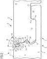
- FIG Fig. 1 A first exemplary embodiment of a panel 1 according to the invention is shown in FIG Fig. 1 shown. It comprises a panel top 2, a panel underside 3, a panel core 4 and complementary locking means 5 and 6, which are provided in pairs on opposite panel edges 7 and 8.
- the panel edges in Fig. 1 can be thought of as the panel edges that belonged to a panel. In practice it is quite common to cut through a panel, for example if the panel is too long at the end of a row of panels. Then it is shortened to a suitable length and cut for the purpose. The separated remnant can usually be used to start a new row of panels.
- Fig. 1 in principle also to be understood as the panel edges of two panels that are not cut through.
- the complementary locking means 5 and 6 of the panel are designed as a pair of complementary hook profiles.
- a hook profile is a receiving hook 9 and the opposite hook profile is a matching locking hook 10.
- the receiving hook 9 has a hook edge 11 away from the body and closer to the body it has a receiving recess 12.
- the receiving recess 12 is open to the top 2 of the panel.
- the locking hook 10 has been arranged closer to the body and has a locking recess 13 open to the underside of the panel 3 and is provided with a locking shoulder 14 away from the body.
- the locking shoulder 14 fits in the vertical joining direction in the receiving recess 12 of the receiving hook 9, d. H. it can be moved down into the receiving recess 12 in a substantially vertical joining direction.
- a gap is provided in the locked state between the bottom of the locking recess 13 and the top of the hook edge 11.
- the locking shoulder sits flat on the bottom of the receiving recess 12.
- Holding surfaces are provided for horizontal locking. They are intended to counteract the moving apart of locked panels in the plane of the panel, perpendicular to the panel edges.
- One of the holding surfaces 11a is arranged proximally on the edge of the hook. It quasi limits the receiving recess 12 of the receiving hook 9.
- the complementary holding surface 14a of the locking hook 10 is provided on the locking shoulder 14 proximally.
- the locking hook 10 has a vertically locking locking contour 15, which is made in one piece from the Material of the panel core 4 is made.
- the locking contour 15 comprises a locking groove 16 which has an approximately triangular cross section.
- a form-locking contour 17 provided on the receiving hook 9 is also made of the same material, which for the purpose of vertical locking fits in a form-fitting manner with the locking contour 15 of the locking hook 10.
- the form-locking contour 17 is designed as a distal projecting web 18.
- the web 18 has an approximately triangular cross section and has a locking surface 19, the surface normal of which is directed obliquely to the underside of the panel 3, and an open surface 20, the surface normal of which is directed obliquely to the top of the panel 2.
- the locking surface of the web 18 acts together with a groove wall 21 of the locking groove.
- the receiving hook 9 has a sealing groove 22, the surface of which is formed from the material of the panel core 4.
- a sealing strip 23 is provided above the locking contour 15 of the locking hook 10, which in turn is formed from the material of the panel core 4 and conforms to the contour of the sealing groove 22.
- the sealing groove 22 of the receiving hook 9 is delimited by a groove edge 24 projecting in the direction of the upper side 2 of the panel, a recess 25 for the groove edge 24 which is open at the bottom being provided on the locking hook 10.
- the sealing groove 22 has a proximal side 26 and a distal side 27 and a groove base 28 facing the groove edge 22.
- the groove base has a convexly curved contour, this curvature also extending to the sides 26 and 27.
- the proximal side wall 26 of the sealing groove 22 merges into an upper abutment surface 29, which is perpendicular to the top of the panel 2 is arranged.
- the distal side wall 27 has a tangent line 30 as a transition into a concave round contour, which forms the upper side 31 of the groove edge 24.
- the groove edge 24 is delimited distally by a lower abutment surface 32, which is arranged perpendicular to the upper side 2 of the panel.
- a wedge-shaped cross-sectional area is formed between the upper abutment surface 29 and the tangent line 30.
- the sealing strip 23 of the locking hook 10 is adapted to the contour of the sealing groove 22 described above and has a virtually wedge-shaped cross section.
- the sealing strip 23 has a proximal strip side 33 which is oriented on the tangent line 30 and a distal strip side 34 which is adapted to the proximal side wall 26 and likewise has a transition into an upper counter-abutment surface 35 which interacts with the abutment surface 29.
- the locking hook 10 is provided with a lower counter-abutment surface 36 to match the lower abutment surface 32 of the receiving hook.
- the lower mating surface 36 is arranged between the downwardly open recess 25 and the locking groove 16.
- a wedge angle ⁇ of 50 ° is provided for the sealing strip of the embodiment of the Fig. 1 .
- This proposed wedge-shaped arrangement is favorable for panels that have a panel core made of swelling material. Sealing groove and sealing strip are easier to fit into one another than, for example, in the case of a sealing groove / sealing strip with parallel sides, because these must have a lot of play in order to be able to fit into one another, but do not seal well.
- the wedge-shaped design promotes tightness because the side wall 26 of the sealing groove 22 is in contact with the distal strip side 34 of the sealing strip 23 and at the same time the distal side wall 27 of the sealing groove 22 has contact with the proximal ledge side 33 of the sealing ledge. Differences in size of the cross-section of the sealing strip on the one hand and of the cross-section of the sealing groove on the other are less critical than in versions whose sealing groove / sealing strip provide parallel surface pairs for sealing.
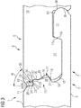
- Fig. 2 shows a development of the panel with an alternative embodiment of the pair of panel edges.
- an edge break is provided on each of the two hook profiles on the top side 2 of the panel.
- the execution is identical to that according to Fig. 1 .
- the panel top 2 On the receiving hook 9, the panel top 2 has an edge break K in the form of a chamfer F1 at the panel edge, which is inclined here at an angle of 35 ° relative to the panel top.
- the locking hook 10 is provided on the top side 2 of the panel with an edge break K in the form of a chamfer F2, which is mirror-inverted and matches the chamfer F1 of the receiving hook 9.
- the two chamfers protect the respective panel edge 7 and 8 respectively.
- the chamfer reduces the risk of breakage damage to the panel edge in question.
- the bevels F1 and F2 form a V-joint, which is visually appealing and, on the whole, is useful for protecting a covering surface, because breakage damage to the panel edges 7 and 8 is less frequent and less extensive.
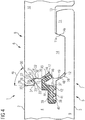
- Fig. 3 is a further development of that panel Fig. 2 shown. Like the previous embodiment, it has edge breaks in the form of chamfers.
- an additional second vertically locking measure is provided.
- a distal surface of the hook edge 11 is provided with a male locking contour M which protrudes in the distal direction. It fits In the locking recess 13 of the locking hook 10, a female locking contour W is provided on a proximal surface, which is in contact with the male locking contour and has a vertically locking effect.
- FIG. 4 Another embodiment of the panel is in Fig. 4 shown which according to the execution Fig. 1 based.
- the positive locking contour 17 of the receiving hook comprises a separate vertical locking element 37, which is held captively in a retaining groove 38 in the receiving hook 9.
- the separate vertical locking element 37 is applied captively in the holding groove 38 provided for this purpose in the receiving hook 9, which can be done automatically during the manufacture of the panel, or separate vertical locking elements are included as individual parts when the panels are delivered in a suitable number.
- a vertical locking element must then be manually inserted in the holding groove 38 of the receiving hook 9.
- a part 39 of the separate vertical locking element protruding from the holding groove 38 forms a spring-elastic latching tab. Due to its elastic properties, this can recede during a joining process if a complementary locking hook is pushed against it. When the locking hook is brought into the final locking position, the protruding part of the separate vertical locking element can automatically emerge in the direction of its neutral position by means of spring elastic tension. This more neutral position of the vertical locking element or its spring-elastic latching tab is at the same time the vertically locking position, which counteracts moving the hook profiles apart in the vertical direction.
- the part of the cross-section of the separate vertical locking element 37, which is held captively in the holding groove 38, has a holding area for this purpose, which has a back 39 and transverse projections 40, 41 and 42 provided on one side on the back 39, which in the applied state point in the direction of the underside of the panel 3 emerge and reach to the opposite groove wall 43 of the holding groove 38.
- the retaining area of the separate vertical locking element (37), which is inserted in a captive manner has a certain excess, which is why the transverse projections 40, 41 and 42 with a certain elastic deformation and pretension ensure the desired captive hold in the retaining groove 38.
- a neck 44 attaches to one end of the back 39.
- the resilient locking tab 45 continues on this neck.
- the resilient locking tab 45 has a free end 46 which abuts the groove wall 21 of the locking groove 16 of the locking hook.
- the vertical locking effect is generated by means of this contact between the free end 46 and the groove wall 21.
- This is expediently coordinated with one another so that the free end 46 of the latching tab 45 always rests on the groove wall 21 with a rest of spring-elastic tension.
- This concept can be designed in such a way that even with a certain wear of the hook profiles, sufficient spring-elastic tension is always maintained and no play can develop between the locked hook profiles in the vertical direction.
- the free end 46 of the resilient latching tab down to the underside of the panel 3.
- the design is in accordance with Fig. 4 modified, namely that there is some air between the groove edge 24 and the downwardly open recess 25 or a cavity 47 is formed there.
- this area of the contours it is intended to ensure the contact of the sealing strip 23 with the groove base 28 of the sealing groove. This is simplified if there is no additional contact between the groove edge 24 and the recess 25 by removing material at this point, so that the cavity 47 can be formed.
- a distal side surface 48 of the locking shoulder 14 is at a distance from a proximal side surface 49 of the receiving recess 12. Air should also remain at this point, or a gap 50. The gap at this point also favors a good fit of the sealing groove 22 and sealing strip 23.
- the same separate vertical locking element 37 can be applied captively to the locking hook 10.
- the locking groove 16 must be changed in order to be able to hold the vertical locking element 37 captively and in a kinematically reversed arrangement, so that the free end 46 of the spring-elastic latching tab 45 is directed upwards to the top side 2 of the panel.
- FIG. 5 Another embodiment according to Fig. 5 has, like the previous one, edge breaks in the form of chamfers F1 and F2.
- the chamfers form a V-joint when placed in mirror image.
- a difference from the previous embodiment is in the design of the locking heel 14.
- the underside of the locking heel 14 is in accordance with Fig. 5 partially cut free, namely a proximal part of the underside is provided with a cut 51. This creates a gap 52 between the cutout 51 and the bottom of the receiving recess 12 in the assembled state of the complementary hook profiles.
- a distal part of the underside of the locking shoulder 14 maintains contact with the bottom of the receiving recess 12.
- This design creates a certain amount on the underside of the panel 3 Resilience of the receiving hook 9.
- FIG. 5 an alternative design illustrates that in the locked state of two panel edges (7, 8), that upper joint is closed, which is formed by the upper abutment surface 29 in contact with the upper counter-abutment surface 35.
- the holding surface 11a attributable to the receiving hook 9 is in contact with the holding surface 14a attributable to the locking hook 10.
- the dashed line indicates an elastic bend at the receiving hook downwards by the dimension t.
- the elastic bending causes a permanent prestress within the locking, namely by means of an arrangement of the holding surfaces 11a / 14a in such a way that they are inclined by an angle ⁇ with respect to the solder on the panel plane.
- a second pair of panel edges 60 and 61 of the panel is shown, which provides a form-fitting tongue and groove connection.
- This pair of panel edges can be combined very well on a square panel with a first pair of edges, which has the complementary hook profiles according to the invention.
- the panel edges according to Fig. 6 dispense with hook profiles and cannot be locked in a joining movement in a direction perpendicular to the panel plane. Instead, one of the panel edges is provided with a tongue profile 62 and the complementary panel edge has a groove profile 63, so that a joining movement is required which includes a movement component of the panel edges in the panel plane towards one another.
- That panel with tongue profile 62 is preferably moved in a certain inclined position in the direction of the slot profile 63 of a lying panel and when the tongue is inserted in the slot, the inclined panel is then pivoted down into the same plane of the lying panel.
- the positive locking is created by the swiveling movement.
- the second pair of edges is designed as in the patent application EP 18155583.0 proposed. These panel edges in turn have means for sealing a joint, which are intended to counter water penetration to the underside of the panel 3.
- the spring profile 62 is provided with a sealing groove 64 and the complementary groove profile 63 has a distally protruding sealing web 65 which fits into the sealing groove 64. Sealing web and sealing groove are each arranged in the material of the panel core 4. In the present panel core 4, this is a material that can and should swell under moisture.
- the tightness of the panel according to the invention can be improved if it is designed as a square panel and as a second pair of edges with the form-fitting tongue and groove profiles EP 18155583.0 is executed.
- the second pair of edges provided with the form-fitting tongue and groove profiles be arranged in relation to the common sealing plane 66 such that an upper side 67 of the sealing web 65 and an upper groove wall 68 of the sealing groove 64, which act as an effective sealing Surfaces are in contact with each other, can be arranged on the level of the common sealing plane 66.
- the groove base 28 of the sealing groove 22, which is in contact with the sealing strip 23, should be arranged such that the lowest point of the groove base 28 is also at the level of the common sealing plane 66, which is shown by the side by side Figures 6 and 7 is illustrated. Otherwise, the locking element is omitted in this illustration for simplicity; however, it is in accordance with the execution Fig. 7 the same locking element 37 is provided as in Figs. 4 and 5 ,
- Fig. 8 again shows a panel 1 according to the invention, which is provided with a separate vertical locking element 69 for the purpose of vertical locking.
- the vertical locking element 69 is provided with a latching tab 70, which in the locked state two panels protrudes from the holding groove 38.
- the vertical locking element 69 is designed to be resilient in a rear region extending into the holding groove 38. In the sense of the invention, this resilient holding area 71 is counted as a holding area because it projects into the holding groove 38.
- each embodiment of the Figures 1-7 be provided with the vertical locking element 69 proposed here with the necessary adaptations of the receiving retaining groove 38 as an expedient form-fitting contour 17.
Landscapes
- Engineering & Computer Science (AREA)
- Architecture (AREA)
- Civil Engineering (AREA)
- Structural Engineering (AREA)
- Finishing Walls (AREA)
- Connection Of Plates (AREA)
Abstract
Description
- Die Erfindung betrifft ein Paneel umfassend eine Paneeloberseite, eine Paneelunterseite, einen Paneelkern sowie komplementäre Verriegelungsmittel, die paarweise an sich gegenüberliegenden Paneelkanten vorgesehen sind, wobei wenigstens ein Paar Verriegelungsmittel mit komplementären Hakenprofilen versehen ist, nämlich einem Aufnahmehaken und diesem gegenüberliegend einem Arretierhaken, mit der Maßgabe, dass der Aufnahmehaken rumpffern angeordnet einen Hakenrand und rumpfnäher angeordnet eine Aufnahmeaussparung aufweist, wobei die Aufnahmeaussparung zur Paneeloberseite offen ist und wobei der Arretierhaken mit einer rumpfnäher angeordneten und zur Paneelunterseite offenen Arretieraussparung versehen ist und einen rumpffern angeordneten Arretierabsatz aufweist, der in senkrechter Fügerichtung in die Aufnahmeaussparung des Aufnahmehakens passt, wobei der Arretierhaken eine vertikal verriegelnd wirkende Arretierkontur hat und der Aufnahmehaken eine Formschlusskontur aufweist, die zwecks vertikaler Verriegelung formschlüssig mit der Arretierkontur des Arretierhakens zusammenpasst, wobei der Arretierhaken rumpfnäher an seinem Arretierabsatz angeordnet eine horizontal verriegelnde Haltefläche aufweist und der Aufnahmehaken rumpffern in der Aufnahmeaussparung angeordnet mit einer horizontal verriegelnden Haltefläche versehen ist, wobei der Aufnahmehaken mit einer Dichtungsrille versehen ist, welche zur Paneeloberseite offen ist, und wobei der Arretierhaken eine zur Paneelunterseite hervorstehende Dichtungsleiste hat, welche im zusammengefügten Zustand der komplementären Hakenprofile in die Dichtungsrille passt.
- Aus der
WO 2007/081267 A1 ist ein gattungsgemäßes Paneel bekannt, das einen Paneelkern aus feuchtigkeitsempfindlichem Material umfasst sowie komplementäre Hakenprofile an dem feuchtigkeitsempfindlichen Paneelkern, nämlich einen Aufnahmehaken sowie einen Arretierhaken. An einer Oberseite des Paneelkerns hat das Paneel darüber hinaus eine elastische Oberflächenschicht. Seitliche Kanten der elastischen Oberflächenschicht können überlappen und bilden selbst eine hakenförmige Verbindung. Dieser Stand der Technik schlägt vor, im Bereich der überlappenden Kanten könne wahlweise ein Dichtungsmittel enthalten sein. Sofern also Dichtungsmittel enthalten ist, kann diejenige überlappende Kante auf der Seite des Aufnahmehakens dann als eine Dichtungsrille aufgefasst werden und die überlappende Kante auf der Seite des Arretierhakens kann als eine Dichtungsleiste aufgefasst werden. - Der Erfindung liegt die Aufgabe zugrunde, ein verbessertes Paneel vorzuschlagen, mit dem die Dichtungswirkung einfacher zu erzielen ist.
- Erfindungsgemäß wird die zugrundeliegende Aufgabe dadurch gelöst, dass die Dichtungsrille und die Dichtungsleiste im Bereich des Paneelkerns angeordnet sind, und dass die Oberfläche der Dichtungsrille aus dem Material des Paneelkerns gebildet ist und/oder die Oberfläche der Dichtungsleiste aus diesem Material des Paneelkerns gebildet ist.
- Die Erfindung kehrt davon ab, im Bereich der Hakenprofile den Paneelkern vor Feuchtigkeit abzuschirmen. Stattdessen wird im Material des Paneelkerns eine Dichtungsrille ausgebildet sowie auch eine Dichtungsleiste ausgebildet.
- Wenn der Paneelkern aus einem Material ist, welches die Eigenschaft hat, Feuchtigkeit aufnehmen zu können und dabei sein Volumen zu vergrößern, wird dies als Quellung bezeichnet. Die Erfindung macht sich diese Eigenschaft zu Nutze und kehrt davon ab, den Paneelkern vor Feuchtigkeit zu schützen. Stattdessen wird ein Paneelkern benutzt, der eine Quelleigenschaft hat, damit die damit einhergehende Volumenausdehnung ausnutzbar ist, um auf diese Weise eine Dichtungswirkung zu erzielen oder um diese Wirkung zu verstärken.
- Zweckmäßig kann darüber hinaus sein, wenn der Aufnahmehaken mit seiner horizontal verriegelnden Haltefläche in der Aufnahmeaussparung so ausgelegt ist, dass eine permanente Vorspannung gegen die horizontal verriegelnde Haltefläche des Arretierabsatzes erzeugbar ist. Dadurch werden die beiden Paneelkanten elastisch gegeneinander gespannt, was die Fuge an der Paneeloberseite geschlossen hält. Auf diese Weise wird die Abdichtung mittels der Dichtungsrille und Dichtungsleiste begünstigt. Die permanente Vorspannung kann beispielsweise durch eine Gestaltung erzielt werden, die eine elastische Auslenkung an der Paneelunterseite vorsieht bei gleichzeitig geschlossener Fuge an der Paneeloberseite sowie einer ebenen fluchtenden Ausrichtung der Paneeloberseiten der verriegelten Paneele.
- Des Weiteren wird es daher als nützlich angesehen, wenn der Paneelkern ein Material umfasst, das eine Quellung durch Feuchtigkeit begünstigt. Beim gattungsgemäßen Paneel wird versucht, Feuchtigkeit nicht bis zum Paneelkern herankommen zu lassen.
- Allgemein ist es bekannt, für Paneele der gattungsgemäßen Art den Paneelkern aus sogenannten quellvergüteten Platten herzustellen, deren Quellvergütung dazu dient, einer Quellung entgegenzuwirken, z.B. durch Zugabe eines Wachsbestandteils bei der Herstellung der Platte. Von dieser Lehre kehrt die Erfindung ab und schlägt stattdessen vor, auf Maßnahmen zur Quellvergütung zu verzichten oder die Quellvergütung des Materials des Paneelkerns zumindest zu reduzieren.
- Einfacherweise kann der Paneelkern einen Holzfaserwerkstoff umfassen. Vorzugsweise wird für das erfindungsgemäße Paneel ein Holzfaserwerkstoff mit reduzierter Quellvergütung oder ganz ohne Quellvergütung verwendet. Ein Paneel aus einem quellvergüteten Holzfaserwerkstoff kann beispielsweise wasserabweisende Bestandteile enthalten, wie Wachs. Dies reduziert die Quellung des Holzfaserwerkstoffs je nach Dosierung des wasserabweisenden Bestandteils.
- Holzfaserwerkstoffe im Sinne dieser Erfindung sind neben hochdichter Holzfaserplatte (HDF), mitteldichter Faserplatte (MDF) und OSB-Platte (engl.: oriented strand board) auch faserhaltige Kompositwerkstoffe wie WPC (engl.: Wood Plastics Composite) oder NFRP (engl.: Natural Fiber Reinforced Plastics).
- Erfindungsgemäß wird die quellende Eigenschaft des Paneelkerns ausgenutzt, um zur Abdichtung verriegelter Paneelkanten beizutragen. Durch die vorgeschlagene Maßnahme bleiben tiefere Bereiche des Paneelkerns überraschenderweise frei von Feuchtigkeit, obwohl wasserabweisende Bestandteile im Holzfaserwerkstoff weggelassen oder mindestens reduziert werden. Überraschend hat sich gezeigt, unter das Niveau von Dichtungsrille und Dichtungsleiste gelangt nahezu keine Feuchtigkeit mehr. Diejenigen Bereiche der Hakenprofile bleiben trocken, welche den Zusammenhalt verriegelter Paneelkanten bewirken, nämlich die Arretierkontur des Arretierhakens sowie die Formschlusskontur des Aufnahmehakens. Entsprechende Tests im Bereich von T-Fugen haben ergeben, dass Wasser, im Bereich einer T-Fuge auf einer Bodenoberfläche, die aus erfindungsgemäßen Paneelen zusammengefügt ist, auch nach langer Dauer nicht bis zur Unterseite des Bodenbelags durchsickern kann.
- Zweckmäßig ist die Dichtungsleiste relativ zur Dichtungsrille ohne Übermaß gestaltet, damit sich diese leicht ineinanderfügen lassen.
- Hilfreich ist es, wenn die Dichtungsrille mit einander gegenüberliegenden Seitenwänden versehen ist, einen Rillengrund hat und distal von einem in Richtung der Paneeloberseite vorstehenden Rillenrand begrenzt ist, wobei die Seitenwände relativ zueinander eine keilförmige Anordnung einnehmen, wobei der Keilwinkel zur Paneeloberseite offen ist, und wobei der Keilwinkel im Bereich von 30° bis 70° liegt, bevorzugt im Bereich von 40° bis 60° und besonders bevorzugt bei 45° bis 55° liegt.
- Wie sich herausgestellt hat ist es besonders hilfreich die vorgeschlagene keilförmige Anordnung der Seitenwände so vorzusehen, dass der Raum zwischen den Seitenwänden zum Rillengrund der Dichtungsrille enger wird. Des Weiteren hilft es, wenn dann auch die Dichtungsleiste Außenflächen hat, welche an die keilförmige Anordnung der Seitenwände der Dichtungsrille angepasst sind.
- Des Weiteren hilft es, dass der Querschnitt der Dichtungsrille zwischen den Seitenwänden und dem Rillengrund jeweils einen runden Übergang aufweist. (z.B. Radius) ... im Unterscheid zum SdT der
Fig. 5c ausWO 2007/081267 , wo rechteckige Querschnitte zu sehen sind) Auf diese Weise durch runde Übergänge und Vermeidung eckiger Konturen ergibt sich eine Gleichmäßigkeit der Quellung, die erfindungsgemäß zur Abdichtung ausgenutzt werden soll. - Ebenfalls nützlich ist zwischen der distalen Seitenwand und dem Rillenrand im Querschnitt ein runder Übergang vorgesehen.
- An die proximale Seitenwand der Dichtungsrille schließt sich nach oben eine Anstoßfläche an, die vorzugsweise senkrecht zur Paneeloberseite angeordnet ist.
- Die distale Fläche des Rillenrandes ist vorzugsweise senkrecht zur Paneeloberseite angeordnet.
- Zweckmäßig ist am Arretierhaken proximal zur Dichtungsleiste eine nach unten in Richtung der Paneelunterseite offene Aussparung vorgesehen. In dieser nach unten offenen Aussparung findet der nach oben vorstehende Rillenrand des Aufnahmehakens Platz. Vorzugsweise ist der Querschnitt der Aussparung größer als der Querschnitt des Rillenrandes, und zwar so dass im zusammengefügten Zustand zwischen einer Oberseite des Rillenrandes und dem Grund der Aussparung ein Hohlraum gebildet ist.
- Als nützlich hat sich herausgestellt, wenn die Dichtungsleiste an die Querschnittsform der Dichtungsrille angepasst ist. Auf diese Weise und durch Vermeidung von eckigen Konturen kann von einer Gleichmäßigkeit der Quellung profitiert werden.
- Ein weiterer Nutzen wird darin gesehen, dass ein separates Vertikalsperrelement vorgesehen ist, und dass das separate Vertikalsperrelement vor einer Verriegelung der Paneelkanten entweder als Bestandteil der Arretierkontur des Arretierhakens vorgesehen ist oder als Bestandteil der Formschlusskontur des Aufnahmehakens vorgesehen ist.
- Einfacherweise weist die Arretierkontur des Arretierhakens eine Haltenut für das separate Vertikalsperrelement auf, wobei die Formschlusskontur des Aufnahmehakens ebenfalls eine Haltenut für das separate Vertikalsperrelement aufweist.
- Zweckmäßig ist entweder die Haltenut im Aufnahmehaken oder die Nut im Arretierhaken als Haltenut hergerichtet, um das separate Vertikalsperrelement vor einer Verriegelung der Paneelkanten verliersicher halten zu können, wobei ein aus der verliersicher haltenden Nut hervorstehender Teil des separaten Vertikalsperrelements während eines Fügevorgangs in Eingriff zu bringen ist mit der jeweils anderen Nut. Das separate Vertikalsperrelement kann demzufolge verliersicher in der Nut des Arretierhakens appliziert sein. Soll es hingegen in der Nut des Aufnahmehakens verliersicher gehalten sein, dann muss es ggf. im Sinne einer kinematischen Umkehr in geänderter Orientierung appliziert werden, um die Funktion zu gewährleisten.
- Als nützlich herausgestellt hat sich, dass relativ zum Paneelkern sowohl die Nut im Aufnahmehaken als auch die Nut im Arretierhaken in distaler Richtung offen ist.
- Einfacherweise hat das separate Vertikalsperrelement einen Haltebereich, der zur verliersicheren Applikation des Vertikalsperrelements mittels einer der Nuten vorgesehen ist, und dass ein hervorstehender Teil des Vertikalsperrelements mit einer Rastlasche versehen ist. D. h. der Haltebereich des Vertikalsperrelements wirkt mit der Nut zusammen, in welcher das Vertikalsperrelement verliersicher gehalten werden soll.
- Der Haltebereich und/oder die Rastlasche des separaten Vertikalsperrelements kann federnd ausgebildet sein, nämlich zwecks automatischer Verrastbarkeit der Rastlasche in einer Nut während eines Fügevorgangs komplementärer Hakenprofile. Durch diese Maßnahme ist eine automatische Verrastung ermöglicht, so dass die Herstellung der vertikalen Verriegelung automatisch erfolgt.
- Zweckmäßig ist zumindest eine mit Hakenprofil versehene Paneelkante an der Paneeloberseite mit einer Kantenbrechung versehen. Falls beide Paneelkanten mit komplementären Verriegelungsmitteln eine Kantenbrechung haben lässt sich so im zusammengefügten Zustand von Paneelen eine Belagsoberfläche mit optisch ansprechender Fuge erzeugen. Die Fuge kann beispielsweise eine V-Fuge sein, die aus zwei gegeneinander stehenden Fasen gebildet ist. Eine Fuge hat den Vorteil, die Paneelkanten zu schützen, insbesondere eine V-Fuge, beziehungsweise die jeweilige Fase bietet guten Schutz für die jeweilige Paneelkante.
- Eine Kantenbrechung kann mit einer Beschichtung versehen sein. Zweckmäßig ist eine solche Beschichtung vorgesehen, welche an der Oberfläche der Kantenbrechung einer Aufnahme von Feuchtigkeit in das Material des Paneelkerns entgegenwirkt. Hierfür ist jedes geeignete abdichtende Beschichtungsmaterial verwendbar, beispielsweise Lack oder Folie. Die erfindungsgemäße Ausnutzung der Quelleigenschaft des Materials des Paneelkerns soll erst an jenen unterhalb einer Kantenbrechung befindlichen Flächen der Paneelkante beginnen und ihre Wirkung dort entfalten, wo eine Abdichtung durch Quellung von Material benötigt und gewünscht wird.
- Nachstehend ist die Erfindung in einer Zeichnung beispielhaft veranschaulicht und detailliert beschrieben. Es zeigen:
- Fig. 1
- ein erstes Paar Paneelkanten des erfindungsgemäßen Paneels im Querschnitt,
- Fig. 2
- eine Weiterbildung des Paneels mit alternativer Ausführungsform des Paneelkantenpaares gemäß
Fig. 1 , - Fig. 3
- eine Weiterbildung des Paneels mit alternativer Ausführungsform des Paneelkantenpaares gemäß
Fig. 2 , - Fig. 4
- eine Ausführungsform des Paneels mit einem ersten Paar Paneelkanten mit separatem Vertikalsperrelement,
- Fig. 5
- eine weitere Ausführungsform des Paneels mit einem ersten Paar Paneelkanten mit separatem Vertikalsperrelement,
- Fig. 6
- ein zweites Paar Paneelkanten des Paneels mit formschlüssiger Nut- und Federverbindung sowie mit Dichtungssteg und Dichtungsnut gemäß der Anmeldung
EP 18155583.0 - Fig. 7
- das erste Paar Paneelkanten gemäß
Fig. 5 mit leerer Nut für ein Vertikalsperrelement, - Fig. 8
- ein weiteres Ausführungsbeispiel mit einem alternativen separaten Vertikalsperrelement.
- Ein erstes Ausführungsbeispiel eines erfindungsgemäßen Paneels 1 ist in
Fig. 1 gezeigt. Es umfasst eine Paneeloberseite 2, eine Paneelunterseite 3, einen Paneelkern 4 sowie komplementäre Verriegelungsmittel 5 und 6, die paarweise an sich gegenüberliegenden Paneelkanten 7 und 8 vorgesehen sind. Die Paneelkanten inFig. 1 können als die Paneelkanten aufgefasst werden, die zu einem Paneel gehört haben. In der Praxis ist es nämlich durchaus üblich ein Paneel durchzutrennen, beispielsweise wenn das Paneel am Ende einer Paneelreihe zu lang ist. Dann wird es auf eine passende Länge gekürzt und zu dem Zweck durchtrennt. Das abgetrennte Reststück kann in der Regel zum Beginn einer neuen Paneelreihe benutzt werden. Dabei wird die Seite mit der Schnittfläche an den Anfang einer neuen Reihe gelegt, so dass am gegenüberliegenden Ende dieses Paneel-Reststücks das passende Verriegelungsmittel vorhanden ist, um die neue Paneelreihe fortzusetzen und ein weiteres Paneel daran zu verriegeln. Komplementäre Verriegelungsmittel eines durchtrennten Paneels passen daher stets zusammen und können miteinander verriegelt werden, wie inFig. 1 gezeigt. - Selbstverständlich können die ausschnittsweise dargestellten Paneelkanten gemäß
Fig. 1 im Prinzip auch als die Paneelkanten zweier Paneele aufgefasst werden, welche nicht durchtrennt sind. - Gemäß dem ersten Ausführungsbeispiel sind die komplementären Verriegelungsmittel 5 und 6 des Paneels als ein Paar komplementärer Hakenprofile ausgebildet. Ein Hakenprofil ist ein Aufnahmehaken 9 und das diesem gegenüberliegende Hakenprofil ist ein dazu passender Arretierhaken 10. Dabei hat der Aufnahmehaken 9 rumpffern angeordnet einen Hakenrand 11 und rumpfnäher weist er eine Aufnahmeaussparung 12 auf. Die Aufnahmeaussparung 12 ist zur Paneeloberseite 2 offen. Der Arretierhaken 10 hat rumpfnäher angeordnet und zur Paneelunterseite 3 offen eine Arretieraussparung 13 und rumpffern ist er mit einem Arretierabsatz 14 versehen. Der Arretierabsatz 14 passt in senkrechter Fügerichtung in die Aufnahmeaussparung 12 des Aufnahmehakens 9, d. h. er lässt in wesentlich senkrechter Fügerichtung in die Aufnahmeaussparung 12 hinab bewegen. Zwischen dem Grund der Arretieraussparung 13 und dem Top des Hakenrandes 11 ist im verriegelten Zustand eine Lücke vorgesehen. Der Arretierabsatz sitzt flächig auf dem Grund der Aufnahmeaussparung 12. Für die horizontale Verriegelung sind Halteflächen vorgesehen. Sie sollen einem Auseinanderbewegen verriegelter Paneele in der Paneelebene und zwar senkrecht zu den Paneelkanten entgegenwirken. Eine der Halteflächen 11a ist am Hakenrand proximal angeordnet. Sie begrenzt quasi die Aufnahmeaussparung 12 des Aufnahmehakens 9. Die komplementäre Haltefläche 14a des Arretierhakens 10 ist am Arretierabsatz 14 proximal vorgesehen.
- Des Weiteren hat der Arretierhaken 10 eine vertikal verriegelnd wirkende Arretierkontur 15, die einstückig aus dem Material des Paneelkerns 4 besteht. Die Arretierkontur 15 umfasst eine Arretiernut 16, die einen etwa dreieckigen Querschnitt hat. Aus demselben Material ist auch eine am Aufnahmehaken 9 vorgesehene Formschlusskontur 17, welche zwecks vertikaler Verriegelung formschlüssig mit der Arretierkontur 15 des Arretierhakens 10 zusammenpasst. Die Formschlusskontur 17 ist als ein distaler hervorstehender Steg 18 ausgebildet. Der Steg 18 hat einen etwa dreieckigen Querschnitt und weist eine Verriegelungsfläche 19 auf, deren Flächennormale schräg zur Paneelunterseite 3 gerichtet ist, sowie eine Freifläche 20, deren Flächennormale schräg zur Paneeloberseite 2 gerichtet ist. Die Verriegelungsfläche des Steges 18 wirkt zusammen mit einer Nutwand 21 der Arretiernut.
- Oberhalb der Formschlusskontur 17 hat der Aufnahmehaken 9 eine Dichtungsrille 22, deren Oberfläche aus dem Material des Paneelkerns 4 gebildet ist.
- Passend dazu ist oberhalb der Arretierkontur 15 des Arretierhakens 10 eine Dichtungsleiste 23 vorgesehen, die ihrerseits aus dem Material des Paneelkerns 4 gebildet ist und sich an die Kontur der Dichtungsrille 22 anschmiegt.
- Die Dichtungsrille 22 des Aufnahmehakens 9 ist von einem in Richtung der Paneeloberseite 2 vorstehenden Rillenrand 24 begrenzt, wobei am Arretierhaken 10 eine nach unten offenen Aussparung 25 für den Rillenrand 24 vorgesehen ist. Die Dichtungsrille 22 hat eine proximale Seite 26 sowie dem Rillenrand 22 zugewandt eine distale Seite 27 sowie einen Rillengrund 28. Der Rillengrund hat eine konvex gekrümmte Kontur, wobei sich diese Krümmung auch zu den Seiten 26 und 27 erstreckt.
- Die proximale Seitenwand 26 der Dichtungsrille 22 geht über in eine obere Anstoßfläche 29, die senkrecht zur Paneeloberseite 2 angeordnet ist. Die distale Seitenwand 27 hat eine Tangentenlinie 30 als Übergang in eine konkav runde Kontur, welche die Oberseite 31 des Rillenrandes 24 bildet. Der Rillenrand 24 ist distal von einer unteren Anstoßfläche 32 begrenzt, die relativ zur Paneeloberseite 2 senkrecht angeordnet ist.
- Zwischen der oberen Anstoßfläche 29 und der Tangentenlinie 30 ist ein keilförmiger Querschnittsbereich gebildet.
- Die Dichtungsleiste 23 des Arretierhakens 10 ist an die oben beschriebene Kontur der Dichtungsrille 22 angepasst und hat quasi einen passend keilförmigen Querschnitt. Die Dichtungsleiste 23 hat eine proximale Leistenseite 33, die sich an der Tangentenlinie 30 orientiert sowie eine distale Leistenseite 34, welche an die proximale Seitenwand 26 angepasst ist und gleichfalls einen Übergang in eine obere Gegenstoßfläche 35 hat, welche mit der Anstoßfläche 29 zusammenwirkt.
- Passend zur unteren Anstoßfläche 32 des Aufnahmehakens ist der Arretierhaken 10 mit einer unteren Gegenstoßfläche 36 versehen. Die untere Gegenstoßfläche 36 ist zwischen der nach unten offenen Aussparung 25 und der Arretiernut 16 angeordnet.
- Für die Dichtungsleiste des Ausführungsbeispiels der
Fig. 1 ist ein Keilwinkel α von 50° vorgesehen. Diese vorgeschlagene keilförmige Anordnung ist günstig für Paneele, die einen Paneelkern aus quellendem Material haben. Dichtungsrille und Dichtungsleiste sind einfacher ineinanderzufügen als beispielsweise bei einer Dichtungsrille/Dichtungsleiste mit parallelen Seiten, weil diese viel Spiel aufweisen müssen um sich ineinanderfügen zu lassen, jedoch schlecht abdichten. Im Unterscheid dazu begünstigt die keilförmige Gestaltung die Dichtheit, weil die Seitenwand 26 der Dichtungsrille 22 Kontakt hat mit der distalen Leistenseite 34 der Dichtungsleiste 23 und gleichzeitig die distale Seitenwand 27 der Dichtungsrille 22 Kontakt mit der proximalen Leistenseite 33 der Dichtungsleiste hat. Größenunterschiede des Querschnitts der Dichtungsleiste einerseits und des Querschnitts der Dichtungsrille andererseits sind weniger kritisch als bei Ausführungen deren Dichtungsrille/Dichtungsleiste parallelen Flächenpaare zur Abdichtung vorsehen. -
Fig. 2 zeigt eine Weiterbildung des Paneels mit alternativer Ausführungsform des Paneelkantenpaares. Im Unterschied zum vorherigen Ausführungsbeispiel ist an beiden Hakenprofilen an der Paneeloberseite 2 jeweils eine Kantenbrechungen vorgesehen. Im Übrigen ist die Ausführung identisch mit jener gemäßFig. 1 . An dem Aufnahmehaken 9 hat die Paneeloberseite 2 an der Paneelkante eine Kantenbrechung K in Form einer Fase F1, die hier in einem Winkel von 35° relativ zur Paneeloberseite geneigt ist. Ebenso ist der Arretierhaken 10 an der Paneeloberseite 2 mit einer Kantenbrechung K in Form einer Fase F2 versehen, welche spiegelbildlich und passend zur Fase F1 des Aufnahmehakens 9 ausgebildet ist. Die beiden Fasen schützen die jeweilige Paneelkante 7 beziehungsweise 8. Die Fase reduziert das Risiko von Bruchschäden an der betreffenden Paneelkante. Gemeinsam bilden die Fasen F1 und F2 eine V-Fuge, die optisch ansprechend ist und insgesamt dem Schutz einer Belagsoberfläche nützt, weil Bruchschäden der Paneelkanten 7 und 8 seltener sind und geringeres Ausmaß annehmen. - Mit
Fig. 3 ist eine Weiterbildung desjenigen Paneels gemäßFig. 2 dargestellt. Es hat ebenso, wie das vorherige Ausführungsbeispiel Kantenbrechungen in Form von Fasen. Darüber hinaus ist eine zusätzliche zweite vertikal verriegelnde Maßnahme vorgesehen. Zu dem Zweck ist eine distale Fläche des Hakenrandes 11 mit einer männlichen Rastkontur M versehen, die in distaler Richtung hervorsteht. Passend dazu ist in der Arretieraussparung 13 des Arretierhakens 10 an einer proximalen Fläche eine weiblichen Rastkontur W vorgesehen, welche in Berührung mit der männlichen Rastkontur ist und vertikal verriegelnd wirkt. - Eine weitere Ausführungsform des Paneels ist in
Fig. 4 gezeigt, welche auf der Ausführung gemäßFig. 1 basiert. Im Unterschied zuFig. 1 umfasst die Formschlusskontur 17 des Aufnahmehakens ein separates Vertikalsperrelement 37, das in einer Haltenut 38 im Aufnahmehaken 9 verliersicher gehalten ist. Das separate Vertikalsperrelement 37 wird vor der Herstellung eines Paneelbelags verliersicher in der dafür vorgesehenen Haltenut 38 des Aufnahmehakens 9 appliziert, was während der Herstellung des Paneels automatisiert vorgenommen werden kann oder separate Vertikalsperrelemente werden bei Auslieferung von Paneelen in entsprechender passender Anzahl als Einzelteile beigelegt. Vor einer Verriegelung komplementärer Hakenprofile muss dann jeweils ein Vertikalsperrelement manuell in der Haltenut 38 des Aufnahmehakens 9 eingefügt werden. - Ein aus der Haltenut 38 hervorstehendes Teil 39 des separaten Vertikalsperrelements bildet eine federelastische Rastlasche. Diese kann während eines Fügevorgangs aufgrund ihrer elastischen Eigenschaft zurückweichen, wenn ein komplementärer Arretierhaken dagegen gestoßen wird. Wenn der Arretierhaken bis in die endgültige Verriegelungsposition gebracht wird, kann das hervorstehende Teil des separaten Vertikalsperrelements automatisch mittels federelastischer Spannung in Richtung seiner neutralen Position wieder hervortreten. Diese neutralere Position des Vertikalsperrelements beziehungsweise seiner federelastischen Rastlasche ist gleichzeitig auch die vertikal verriegelnde Position, welche einem Auseinanderbewegen der Hakenprofile in vertikaler Richtung entgegenwirkt.
- Das Teil des Querschnitts des separaten Vertikalsperrelements 37, das verliersicher in der Haltenut 38 gehalten ist, weist dafür einen Haltebereich auf, der einen Rücken 39 hat sowie einseitig am Rücken 39 vorgesehene Quervorsprünge 40, 41 und 42, die im applizierten Zustand in Richtung der Paneelunterseite 3 hervortreten und bis zur gegenüberlegenden Nutwand 43 der Haltenut 38 reichen. Im Verhältnis zur Weite der Haltenut hat der verliersicher eingefügte Haltebereich des separaten Vertikalsperrelements (37) ein gewisses Übermaß, weswegen die Quervorsprünge 40, 41 und 42 mit gewisser elastischer Verformung und Vorspannung für den gewünschten verliersicheren Halt in der Haltenut 38 sorgen. Gegenüberliegend zu den drei Quervorsprüngen 40, 41 und 42 setzt an einem Ende des Rückens 39 ein Hals 44 an. An diesem Hals wiederum setzt sich die federelastische Rastlasche 45 fort. Die federelastische Rastlasche 45 hat ein freies Ende 46, welches gegen die Nutwand 21 der Arretiernut 16 des Arretierhakens stößt. Mittels dieses Kontaktes zwischen dem freien Ende 46 und der Nutwand 21 wird die vertikale Verriegelungswirkung erzeugt. Zweckmäßig ist dies so aufeinander abgestimmt, damit das freie Ende 46 der Rastlasche 45 stets mit einem Rest an federelastischer Spannung an der Nutwand 21 anliegt. Dieses Konzept kann so ausgelegt sein, dass selbst bei einem gewissen Verschleiß der Hakenprofile stets genügend federelastische Spannung erhalten bleibt und sich in vertikaler Richtung kein Spiel zwischen den verriegelten Hakenprofilen ausbilden kann. Im Beispiel der
Fig. 4 zeigt das freie Ende 46 der federnden Rastlasche nach unten zur Panelunterseite 3. - Im Bereich der Dichtungsrille 22 des Aufnahmehakens und der Dichtungsleiste 23 des Arretierhakens ist die Gestaltung gemäß
Fig. 4 modifiziert und zwar befindet sich zwischen dem Rillenrand 24 und der nach unten offenen Aussparung 25 etwas Luft beziehungsweise ist dort ein Hohlraum 47 ausgebildet. In diesem Bereich der Konturen ist beabsichtigt, den Kontakt der Dichtungsleiste 23 mit dem Rillengrund 28 der Dichtungsrille sicherzustellen. Dies wird vereinfacht, wenn auf einen zusätzlichen Kontakt zwischen Rillenrand 24 und Aussparung 25 verzichtet wird, indem an dieser Stelle Material entfernt ist, so dass der Hohlraum 47 gebildet werden kann. - Eine distale Seitenfläche 48 des Arretierabsatzes 14 hat im zusammengefügten Zustand der Hakenprofile einen Abstand zu einer proximalen Seitenfläche 49 der Aufnahmeaussparung 12. Auch an dieser Stelle soll Luft bleiben, beziehungsweise eine Lücke 50. Die Lücke an dieser Stelle begünstigt ebenfalls ein gutes Ineinanderpassen von Dichtungsrille 22 und Dichtungsleiste 23.
- Der Vollständigkeit halber sei erwähnt, dass bei einer anderen Ausführung dasselbe separate Vertikalsperrelement 37 verliersicher am Arretierhaken 10 appliziert werden kann. Dafür muss die Arretiernut 16 geändert werden um das Vertikalsperrelement 37 verliersicher halten zu können und zwar in kinematisch umgekehrter Anordnung, so dass das freie Ende 46 der federelastischen Rastlasche 45 nach oben zur Paneeloberseite 2 gerichtet ist.
- Ein weiteres Ausführungsbeispiel gemäß
Fig. 5 hat, wie das Vorherige, wiederum Kantenbrechungen in Form von Fasen F1 und F2. Die Fasen bilden spiegelbildlich aneinander gesetzt gemeinsam eine V-Fuge. Ein Unterschied gegenüber der vorherigen Ausführungsform besteht in der Gestaltung des Arretierabsatzes 14. Die Unterseite des Arretierabsatzes 14 ist gemäßFig. 5 teilweise freigeschnitten und zwar ist ein proximaler Teil der Unterseite mit einem Freischnitt 51 versehen. Dadurch entsteht im zusammengefügten Zustand der komplementären Hakenprofile ein Spalt 52 zwischen dem Freischnitt 51 und dem Grund der Aufnahmeaussparung 12. Ein distaler Teil der Unterseite des Arretierabsatzes 14 behält Kontakt mit dem Grund der Aufnahmeaussparung 12. Diese Gestaltung schafft an der Paneelunterseite 3 eine gewisse Nachgiebigkeit des Aufnahmehakens 9. Diese Nachgiebigkeit ist vorteilhaft, wenn auf buckeligem Untergrund ein Belag aus erfindungsgemäßen Paneelen hergestellt werden soll. Ein nach oben hervorstehender Buckel im Untergrund, wenn er sich unterhalb verriegelter Hakenprofile befindet, kann durch die erwähnte Nachgiebigkeit etwas kompensiert werden. Wenn sich die Paneelunterseite 3 aufgrund eines Buckels nach oben drückt verengt sich lediglich der Spalt 52 und eine Anhebung der Paneeloberseite 2 kann vermieden oder vermindert werden. - Mittels einer gestrichelten Linie ist in
Fig. 5 eine alternative Gestaltung veranschaulicht, welche vorsieht, dass im verriegelten Zustand zweier Paneelkanten (7, 8), jene obere Fuge geschlossen ist, welche durch die obere Anstoßfläche 29 im Kontakt mit der oberen Gegenstoßfläche 35 gebildet ist. Dabei ist gleichzeitig die dem Aufnahmehaken 9 zuzurechnende Haltefläche 11a in Kontakt mit der dem Arretierhaken 10 zuzurechnenden Haltefläche 14a. Die gestrichelte Linie deutet eine elastische Biegung am Aufnahmehaken nach unten um das Maß t an. Die elastische Biegung bewirkt eine permanente Vorspannung innerhalb der Verriegelung, nämlich mittels einer Anordnung der Halteflächen 11a/14a so, dass sie gegenüber dem Lot auf der Paneelebene um einen Winkel β geneigt sind. Dies hält insbesondere die erwähnte Fuge zwischen oberer Anstoßfläche 29 und oberer Gegenstoßfläche 35 geschlossen. Die hier vorgeschlagene Ausbildung der Hakenprofile, welche eine permanente Vorspannung innerhalb der Verriegelung erzeugen und die obere Fuge schließen soll kann selbstverständlich auch als Alternative bei jedem der Ausführungsbeispiele derFiguren 1 bis 4 vorgesehen sein. - Anhand von
Fig. 6 ist ein zweites Paar Paneelkanten 60 und 61 des Paneels dargestellt, welches eine formschlüssige Nut- und Federverbindung vorsieht. Dieses Paar Paneelkanten lässt sich an einem viereckigen Paneel sehr gut kombinieren mit einem ersten Kantenpaar, welches die erfindungsgemäßen komplementären Hakenprofile hat. Die Paneelkanten gemäßFig. 6 verzichten auf Hakenprofile und lassen sich nicht in einer Fügebewegung in einer Richtung senkrecht zur Paneelebene verriegeln. Stattdessen ist eine der Paneelkanten mit einem Federprofil 62 versehen und die komplementäre Paneelkante hat ein Nutprofil 63, so dass eine Fügebewegung erforderlich ist, die eine Bewegungskomponente der Paneelkanten in der Paneelebene aufeinander zu beinhaltet. Vorzugsweise wird dasjenige Paneel mit Federprofil 62 in gewisser Schrägstellung in Richtung des Nutprofils 63 eines liegenden Paneels zu bewegt und wenn die Feder in der Nut eingesetzt ist, wird das schräggestellte Paneel anschließend in dieselbe Ebene des liegenden Paneels herabgeschwenkt. Durch die herabschwenkende Bewegung wird die formschlüssige Verriegelung hergestellt. - Das zweite Kantenpaar ist so gestaltet, wie in der Patentanmeldung
EP 18155583.0 - Die Dichtheit des erfindungsgemäßen Paneels kann verbessert werden, wenn es als viereckiges Paneel ausgeführt wird und als zweites Kantenpaar mit den formschlüssigen Nut- und Federprofilen gemäß
EP 18155583.0 - Darüber hinaus wurde gefunden, dass die Dichtheit des viereckigen Paneels noch weiter verbessert werden kann, wenn eine definierte gemeinsame Dichtungsebene 66 vorgesehen wird. Es soll das Kantenpaar mit den Hakenprofilen dieselbe Dichtungsebene nutzen, wie auch das zweite Kantenpaar, welches die formschlüssigen Nut- und Federprofile (62, 63) gemäß
EP 18155583.0 - Zu dem Zweck wird vorgeschlagen, es soll dasjenige mit den formschlüssigen Nut- und Federprofilen versehene zweite Kantenpaar in Bezug auf die gemeinsame Dichtungsebene 66 so angeordnet sein, dass eine Oberseite 67 des Dichtungssteges 65 sowie eine obere Nutwand 68 der Dichtungsnut 64, welche als wirksame dichtende Flächen miteinander in Berührung stehen, auf dem Niveau der gemeinsamen Dichtungsebene 66 angeordnet sein.
- In Bezug auf das Kantenpaar mit den Hakenprofilen, wie in
Fig. 7 dargestellt, soll der Rillengrund 28 der Dichtungsrille 22, welcher mit der Dichtungsleiste 23 in Berührung ist, so angeordnet sein, dass der tiefste Punkt des Rillengrundes 28 gleichfalls auf dem Niveau der gemeinsamen Dichtungsebene 66 liegt, welche durch die nebeneinander gezeigtenFiguren 6 und 7 veranschaulicht ist. Im Übrigen ist in dieser Darstellung vereinfachend das Sperrelement weggelassen; es ist jedoch für die Ausführung gemäßFig. 7 dasselbe Sperrelement 37 vorgesehen, wie inFigs. 4 und5 . - Auf diese Weise ist erreicht, dass dichtend in Berührung stehende Flächen beider Kantenpaare, weil sie in derselben Dichtungsebene 66 angeordnet sind, auch in den Ecken der Paneele keine Dichtheitslücken entstehen lassen.
-
Fig. 8 zeigt wiederum ein erfindungsgemäßes Paneel 1, das mit einem separaten Vertikalsperrelement 69 zwecks vertikaler Verriegelung versehen ist. Im Unterschied zur den Ausführungen gemäßFig. 4 und5 ist das Vertikalsperrelement 69 mit einer Rastlasche 70 versehen, die im verriegelten Zustand zweier Paneele aus der Haltenut 38 hervorsteht. An einem in die Haltenut 38 hineinreichenden rückwärtigen Bereich ist das Vertikalsperrelement 69 federelastisch ausgebildet. Dieser federelastische Haltebereich 71 wird im Sinne der Erfindung zum Haltebereich gezählt, weil er in die Haltenut 38 ragt. Die Funktion des federelastischen Haltebereichs 71 besteht jedoch zumindest hauptsächlich darin, Federenergie zu speichern und diese als elastische Vorspannung nach vorne in die Rastlasche 70 zu übertragen, welche im verriegelten Zustand zweier Paneele aus der Haltenut 38 hervortritt, wie inFig. 8 zu sehen. Selbstverständlich kann jedes Ausführungsbeispiel derFiguren 1-7 mit dem hier vorgeschlagenen Vertikalsperrelement 69 mit den nötigen Anpassungen der aufnehmenden Haltenut 38 als zweckmäßige Formschlusskontur 17 versehen sein. -
- 1
- Paneel
- 2
- Paneeloberseite
- 3
- Paneelunterseite
- 4
- Paneelkern
- 5
- Verriegelungsmittel
- 6
- Verriegelungsmittel
- 7
- Paneelkante
- 8
- Paneelkante
- 9
- Aufnahmehaken
- 10
- Arretierhaken
- 11
- Hakenrand
- 11a
- horizontal verriegelnde Haltefläche
- 12
- Aufnahmeaussparung
- 13
- Arretieraussparung
- 14
- Arretierabsatz
- 14a
- horizontal verriegelnde Haltefläche
- 15
- Arretierkontur
- 16
- Arretiernut
- 17
- Formschlusskontur
- 18
- Steg
- 19
- Verriegelungsfläche
- 20
- Freifläche
- 21
- Nutwand (Arretiernut)
- 22
- Dichtungsrille
- 23
- Dichtungsleiste
- 24
- Rillenrand
- 25
- Aussparung
- 26
- proximale Seitenwand
- 27
- distale Seitenwand
- 28
- Rillengrund
- 29
- obere Anstoßfläche
- 30
- Tangentenlinie
- 31
- Oberseite (Rillenrand)
- 32
- unter Anstoßfläche
- 33
- proximale Leistenseite
- 34
- distale Leistenseite
- 35
- obere Gegenstoßfläche
- 36
- untere Gegenstoßfläche
- 37
- separates Vertikalsperrelement
- 38
- Haltenut
- 39
- Rücken
- 40
- Quervorsprung
- 41
- Quervorsprung
- 42
- Quervorsprung
- 43
- Nutwand
- 44
- Hals
- 45
- federelastische Rastlasche
- 46
- freies Ende
- 47
- Hohlraum
- 48
- distale Seitenfläche
- 49
- proximale Seitenfläche
- 50
- Lücke
- 51
- Freischnitt
- 52
- Spalt
- 60
- Paneelkante
- 61
- Paneelkante
- 62
- Federprofil
- 63
- Nutprofil
- 64
- Dichtungsnut
- 65
- Dichtungssteg
- 66
- gemeinsame Dichtungsebene
- 67
- Oberseite (Dichtungssteg)
- 68
- obere Nutwand (Dichtungsnut)
- 69
- separates Vertikalsperrelement
- 70
- Rastlasche
- 71
- federelastischer Haltebereich
- F1
- Fase
- F2
- Fase
- M
- männliche Rastkontur
- W
- weibliche Rastkontur
- α
- Keilwinkel
- β
- Winkel
Claims (14)
- Paneel (1) umfassend eine Paneeloberseite (2), eine Paneelunterseite (3), einen Paneelkern (4)sowie komplementäre Verriegelungsmittel (5, 6), die paarweise an sich gegenüberliegenden Paneelkanten (7, 8) vorgesehen sind, wobei wenigstens ein Paar Verriegelungsmittel mit komplementären Hakenprofilen versehen ist, nämlich einem Aufnahmehaken (9) und diesem gegenüberliegend einem Arretierhaken (10), mit der Maßgabe, dass der Aufnahmehaken (10) rumpffern angeordnet einen Hakenrand (11) und rumpfnäher angeordnet eine Aufnahmeaussparung (12) aufweist, wobei die Aufnahmeaussparung (12) zur Paneeloberseite (2) offen ist und wobei der Arretierhaken (9) mit einer rumpfnäher angeordneten und zur Paneelunterseite (3) offenen Arretieraussparung (13) versehen ist und einen rumpffern angeordneten Arretierabsatz (14) aufweist, der in senkrechter Fügerichtung in die Aufnahmeaussparung (12) des Aufnahmehakens (9) passt, wobei der Arretierhaken (10) eine vertikal verriegelnd wirkende Arretierkontur (15) hat und der Aufnahmehaken (9) eine Formschlusskontur (17) aufweist, die zwecks vertikaler Verriegelung formschlüssig mit der Arretierkontur (15) des Arretierhakens (10) zusammenpasst, wobei der Arretierhaken (10) rumpfnäher an seinem Arretierabsatz (14) angeordnet eine horizontal verriegelnde Haltefläche (14a) aufweist und der Aufnahmehaken (9) rumpffern in der Aufnahmeaussparung (12) angeordnet mit einer horizontal verriegelnde Haltefläche (11a) versehen ist, wobei der Aufnahmehaken (9) mit einer Dichtungsrille (22) versehen ist, welche zur Paneeloberseite (2) offen ist, und wobei der Arretierhaken (10) eine zur Paneelunterseite (3) hervorstehende Dichtungsleiste (23) hat, welche im zusammengefügten Zustand der komplementären Hakenprofile in die Dichtungsrille (22) passt, dadurch gekennzeichnet, dass die Dichtungsrille (22) und die Dichtungsleiste (23) im Bereich des Paneelkerns (4) angeordnet sind, und dass die Oberfläche der Dichtungsrille (22) aus dem Material des Paneelkerns (4) gebildet ist und/oder die Oberfläche der Dichtungsleiste (23) aus dem Material des Paneelkerns (4) gebildet ist.
- Paneel nach Anspruch 1, dadurch gekennzeichnet, dass der Paneelkern (4) aus einem Material ist, welches die Eigenschaft hat, Feuchtigkeit aufnehmen zu können und dabei sein Volumen zu vergrößern.
- Paneel nach Anspruch 1 oder 2, dadurch gekennzeichnet, dass der Paneelkern (4) einen Holzfaserwerkstoff umfasst.
- Paneel nach einem der Ansprüche 1 bis 3, dadurch gekennzeichnet, dass die Dichtungsrille (22) mit einander gegenüberliegenden Seitenwänden (26, 27) versehen ist, einen Rillengrund (28) hat und distal von einem in Richtung der Paneeloberseite (2) vorstehenden Rillenrand (24) begrenzt ist, wobei die Seitenwände (26, 27) relativ zueinander eine keilförmige Anordnung einnehmen, wobei der Keilwinkel (α) zur Paneeloberseite (2) offen ist, und wobei der Keilwinkel (α) im Bereich von 30° bis 70° liegt, bevorzugt im Bereich von 40° bis 60° und besonders bevorzugt bei 45° bis 55° liegt.
- Paneel nach Anspruch 4, dadurch gekennzeichnet, dass der Querschnitt der Dichtungsrille (22) zwischen den Seitenwänden (26, 27) und dem Rillengrund (28) jeweils einen runden Übergang aufweist.
- Paneel nach Anspruch 5, dadurch gekennzeichnet, dass zwischen der distalen Seitenwand (27) und dem Rillenrand (28) im Querschnitt ein runder Übergang vorgesehen ist.
- Paneel nach einem der Ansprüche 1 bis 6, dadurch gekennzeichnet, dass die Dichtungsleiste (23) an die Querschnittsform der Dichtungsrille (22) angepasst ist.
- Paneel nach einem der Ansprüche 1 bis 7, dadurch gekennzeichnet, dass eine separates Vertikalsperrelement (37) vorgesehen ist, und dass das separate Vertikalsperrelement (37, 69) vor einer Verriegelung der Paneelkanten (7, 8) entweder als Bestandteil der Arretierkontur (15) des Arretierhakens (10) integriert ist oder als Bestandteil der Formschlusskontur (17) des Aufnahmehakens (9) integriert ist.
- Paneel nach Anspruch 8, dadurch gekennzeichnet, dass die Arretierkontur (15) des Arretierhakens (10) eine Haltenut (38) für das separate Vertikalsperrelement (37, 69) aufweist, und dass die Formschlusskontur des Aufnahmehakens ebenfalls eine Haltenut (38) für das separate Vertikalsperrelement (37, 69) aufweist.
- Paneel nach Anspruch 8 oder 9, dadurch ge - kennzeichnet, dass entweder die Haltenut (38) im Aufnahmehaken (9) ist oder die Nut (16) im Arretierhaken (10) ist als Haltenut hergerichtet, um das separate Vertikalsperrelement (37, 69) vor einer Verriegelung der Paneelkanten (7, 8) verliersicher halten zu können, wobei ein aus der Haltenut (38) hervorstehender Teil des separaten Vertikalsperrelements (37) während eines Fügevorgangs in Eingriff zu bringen ist mit der jeweils anderen Nut.
- Paneel nach Anspruch 9 oder 10, dadurch gekennzeichnet, dass relativ zum Paneelkern (4) sowohl die Haltenut (38) im Aufnahmehaken (9) als auch die Nut (16) im Arretierhaken (10) in distaler Richtung offen ist.
- Paneel nach einem der Ansprüche 8 bis 11, dadurch gekennzeichnet, dass das separate Vertikalsperrelement (37, 69) einen Haltebereich hat, der zur verliersicheren Applikation des Vertikalsperrelements mittels einer der Nuten vorgesehen ist, und dass ein hervorstehender Teil des Vertikalsperrelements mit einer Rastlasche (45, 70) versehen ist.
- Paneel nach Anspruch 12, dadurch gekennzeichnet, dass der Haltebereich und/oder die Rastlasche (45, 70) des separaten Vertikalsperrelements (37, 69) federnd ausgebildet ist zwecks automatischer Verrastbarkeit der Rastlasche (45, 70) in einer Nut (16) während eines Fügevorgangs komplementärer Hakenprofile.
- Paneel nach einem der Ansprüche 1 bis 13, dadurch gekennzeichnet, dass zumindest eine mit Hakenprofile versehene Paneelkante (7, 8) an der Paneeloberseite (2) mit einer Kantenbrechung (F1, F2) versehen ist.
Priority Applications (4)
| Application Number | Priority Date | Filing Date | Title |
|---|---|---|---|
| EP18178064.4A EP3581732B1 (de) | 2018-06-15 | 2018-06-15 | Paneel mit dichtungsrille und dichtungsleiste |
| PCT/EP2019/065465 WO2019238811A1 (de) | 2018-06-15 | 2019-06-13 | Paneel |
| US17/252,569 US11608646B2 (en) | 2018-06-15 | 2019-06-13 | Panel |
| CN201980040330.4A CN112334625B (zh) | 2018-06-15 | 2019-06-13 | 嵌板 |
Applications Claiming Priority (1)
| Application Number | Priority Date | Filing Date | Title |
|---|---|---|---|
| EP18178064.4A EP3581732B1 (de) | 2018-06-15 | 2018-06-15 | Paneel mit dichtungsrille und dichtungsleiste |
Publications (2)
| Publication Number | Publication Date |
|---|---|
| EP3581732A1 true EP3581732A1 (de) | 2019-12-18 |
| EP3581732B1 EP3581732B1 (de) | 2022-12-07 |
Family
ID=62705408
Family Applications (1)
| Application Number | Title | Priority Date | Filing Date |
|---|---|---|---|
| EP18178064.4A Active EP3581732B1 (de) | 2018-06-15 | 2018-06-15 | Paneel mit dichtungsrille und dichtungsleiste |
Country Status (4)
| Country | Link |
|---|---|
| US (1) | US11608646B2 (de) |
| EP (1) | EP3581732B1 (de) |
| CN (1) | CN112334625B (de) |
| WO (1) | WO2019238811A1 (de) |
Cited By (5)
| Publication number | Priority date | Publication date | Assignee | Title |
|---|---|---|---|---|
| EP3892793A1 (de) * | 2020-04-08 | 2021-10-13 | Akzenta Paneele + Profile GmbH | Paneel mit bruchfesten koppelelementen |
| WO2022169391A1 (en) * | 2021-02-03 | 2022-08-11 | Välinge Innovation AB | Building panels comprising a locking device |
| EP4141193A1 (de) | 2021-08-23 | 2023-03-01 | Fritz Egger GmbH & Co. OG | Paneel, insbesondere fussbodenpaneel, mit dichtfunktion |
| EP4660393A1 (de) * | 2024-06-05 | 2025-12-10 | Akzenta Paneele + Profile GmbH | Dekorpaneel mit durchlaufsicheren verbindungsmitteln |
| WO2025252373A1 (de) * | 2024-06-05 | 2025-12-11 | Akzenta Paneele + Profile Gmbh | Dekorpaneel mit durchlaufsicheren verbindungsmitteln |
Families Citing this family (9)
| Publication number | Priority date | Publication date | Assignee | Title |
|---|---|---|---|---|
| EP4257775B1 (de) * | 2020-05-05 | 2025-07-09 | Franz Eschlbeck | Paneel |
| EP3971366A1 (de) * | 2020-09-17 | 2022-03-23 | Surface Technologies GmbH & Co. KG | Paneel |
| EP3971364A1 (de) * | 2020-09-17 | 2022-03-23 | Surface Technologies GmbH & Co. KG | Paneel |
| EP4314437A4 (de) * | 2021-04-01 | 2025-03-05 | Välinge Innovation AB | Bauplatte oder satz aus bauplatten und verriegelungsvorrichtungen dafür |
| US12523045B2 (en) * | 2021-04-19 | 2026-01-13 | “Barlinek” Spółka Akcyjna | Joint of floor panels |
| DE202021003901U1 (de) * | 2021-12-30 | 2022-02-09 | Surface Technologies Gmbh & Co. Kg | Set aus zwei Paneelen zur Verkleidung einer Oberfläche und einem Paneelverbindungselement, Paneelverbindungselement und Verwendung eines Paneelverbindungselements |
| WO2023140763A1 (en) * | 2022-01-21 | 2023-07-27 | Välinge Innovation AB | Set of panels with mechanical positioning means |
| FR3157452A1 (fr) * | 2023-12-20 | 2025-06-27 | Inovame | Lame rectangulaire mince de revêtement pour la pose en ligne |
| CN119392884A (zh) * | 2024-10-30 | 2025-02-07 | 常州市贝美家居科技有限公司 | 一种包含耦合部件的地板 |
Citations (3)
| Publication number | Priority date | Publication date | Assignee | Title |
|---|---|---|---|---|
| EP0624696A2 (de) * | 1993-05-09 | 1994-11-17 | Polygal | Leichtbauplatten-Montage |
| WO2007081267A1 (en) | 2006-01-12 | 2007-07-19 | Välinge Innovation AB | Moisture proof set of floorboards and flooring |
| US20180002933A1 (en) * | 2015-01-16 | 2018-01-04 | Ceraloc Innovation Ab | Mechanical locking system for floor panels |
Family Cites Families (34)
| Publication number | Priority date | Publication date | Assignee | Title |
|---|---|---|---|---|
| US2740167A (en) * | 1952-09-05 | 1956-04-03 | John C Rowley | Interlocking parquet block |
| US3385182A (en) * | 1965-09-27 | 1968-05-28 | Harvey Aluminum Inc | Interlocking device for load bearing surfaces such as aircraft landing mats |
| US6345481B1 (en) * | 1997-11-25 | 2002-02-12 | Premark Rwp Holdings, Inc. | Article with interlocking edges and covering product prepared therefrom |
| EP1169528B1 (de) * | 2000-03-07 | 2002-08-28 | E.F.P. Floor Products Fussböden GmbH | Mechanische verbindung von paneelen |
| SE522860C2 (sv) * | 2000-03-10 | 2004-03-09 | Pergo Europ Ab | Vertikalt förenade golvelement innefattande en kombination av olika golvelement |
| DE10206877B4 (de) * | 2002-02-18 | 2004-02-05 | E.F.P. Floor Products Fussböden GmbH | Paneel, insbesondere Fussbodenpaneel |
| DE10252864A1 (de) * | 2002-05-31 | 2004-05-27 | Kronotec Ag | Fussbodenpaneel |
| US7617651B2 (en) * | 2002-11-12 | 2009-11-17 | Kronotec Ag | Floor panel |
| SE0300642D0 (sv) * | 2003-03-11 | 2003-03-11 | Pergo Europ Ab | Process for sealing a joint |
| CN2673990Y (zh) * | 2003-05-08 | 2005-01-26 | 北京克诺森华地板有限公司 | 三舌多锁扣拼接结构 |
| DE20313661U1 (de) * | 2003-09-05 | 2003-11-13 | Kronospan Technical Co. Ltd., Nikosia | Paneel mit geschützter V-Fuge |
| US20050166516A1 (en) * | 2004-01-13 | 2005-08-04 | Valinge Aluminium Ab | Floor covering and locking systems |
| DE102004028757B4 (de) | 2004-04-02 | 2007-11-15 | hülsta-werke Hüls GmbH & Co. KG. | Paneelelement zur Boden-, Wand- und/oder Deckenverlegung sowie Verfahren zum Verlegen eines Belages, insbesondere eines Boden-, Wand- und/oder Deckenbelages |
| DE102005006532A1 (de) | 2005-02-11 | 2006-08-24 | Kaindl Flooring Gmbh | Paneel mit dekorativer Schicht |
| DE102005028072B4 (de) * | 2005-06-16 | 2010-12-30 | Akzenta Paneele + Profile Gmbh | Fußbodenpaneel |
| DE102006057491A1 (de) | 2006-12-06 | 2008-06-12 | Akzenta Paneele + Profile Gmbh | Paneel sowie Bodenbelag |
| DE102007002590A1 (de) * | 2007-01-12 | 2008-07-31 | Akzenta Paneele + Profile Gmbh | Paneel sowie Bodenbelag |
| DE102008031167B4 (de) * | 2008-07-03 | 2015-07-09 | Flooring Technologies Ltd. | Verfahren zum Verbinden und Verriegeln leimlos zu verlegender Fußbodenpaneele |
| DE202008010555U1 (de) * | 2008-08-08 | 2009-12-17 | Akzenta Paneele + Profile Gmbh | Kunststoffpaneel mit Hakenprofil |
| DE202008011589U1 (de) * | 2008-09-01 | 2008-11-27 | Akzenta Paneele + Profile Gmbh | Fußbodenpaneel aus Kunststoff mit mechanischen Verriegelungskanten |
| CN201671292U (zh) | 2010-05-10 | 2010-12-15 | 德尔国际地板有限公司 | 一种仿实木模压地板 |
| DE102010063976B4 (de) * | 2010-12-22 | 2013-01-17 | Akzenta Paneele + Profile Gmbh | Paneel |
| SG193535A1 (en) * | 2011-03-18 | 2013-10-30 | Inotec Internat Pty Ltd | Vertical joint system and associated surface covering system |
| US8806832B2 (en) * | 2011-03-18 | 2014-08-19 | Inotec Global Limited | Vertical joint system and associated surface covering system |
| US8596013B2 (en) * | 2012-04-04 | 2013-12-03 | Valinge Innovation Ab | Building panel with a mechanical locking system |
| US10316526B2 (en) * | 2014-08-29 | 2019-06-11 | Valinge Innovation Ab | Vertical joint system for a surface covering panel |
| PL4379167T3 (pl) * | 2014-09-26 | 2026-02-09 | Unilin, Bv | Panel podłogowy do tworzenia pokrycia podłogowego |
| DE202014010455U1 (de) * | 2014-09-30 | 2015-08-03 | Akzenta Paneele + Profile Gmbh | Paneel |
| US10876301B2 (en) * | 2014-09-30 | 2020-12-29 | Akzenta Paneele + Profile Gmbh | Panel with complimentary locking elements |
| EP3245354B1 (de) * | 2015-01-16 | 2026-04-15 | Unilin BV | Bodenplatte zur formung eines bodenbelags |
| KR102535444B1 (ko) * | 2017-03-21 | 2023-05-22 | 플로어링 인더스트리즈 리미티드 에스에이알엘 | 플로어 커버링을 형성하기 위한 플로어 패널 |
| US11015351B2 (en) * | 2017-03-21 | 2021-05-25 | Flooring Industries Limited, Sarl | Floor panel for forming a floor covering |
| EP3524750A1 (de) * | 2018-02-07 | 2019-08-14 | Akzenta Paneele + Profile GmbH | Paneel |
| EP3626908A1 (de) * | 2018-09-18 | 2020-03-25 | Akzenta Paneele + Profile GmbH | Quellbare dichtlippe |
-
2018
- 2018-06-15 EP EP18178064.4A patent/EP3581732B1/de active Active
-
2019
- 2019-06-13 US US17/252,569 patent/US11608646B2/en active Active
- 2019-06-13 WO PCT/EP2019/065465 patent/WO2019238811A1/de not_active Ceased
- 2019-06-13 CN CN201980040330.4A patent/CN112334625B/zh active Active
Patent Citations (3)
| Publication number | Priority date | Publication date | Assignee | Title |
|---|---|---|---|---|
| EP0624696A2 (de) * | 1993-05-09 | 1994-11-17 | Polygal | Leichtbauplatten-Montage |
| WO2007081267A1 (en) | 2006-01-12 | 2007-07-19 | Välinge Innovation AB | Moisture proof set of floorboards and flooring |
| US20180002933A1 (en) * | 2015-01-16 | 2018-01-04 | Ceraloc Innovation Ab | Mechanical locking system for floor panels |
Cited By (12)
| Publication number | Priority date | Publication date | Assignee | Title |
|---|---|---|---|---|
| EP3892793A1 (de) * | 2020-04-08 | 2021-10-13 | Akzenta Paneele + Profile GmbH | Paneel mit bruchfesten koppelelementen |
| WO2021204903A1 (de) * | 2020-04-08 | 2021-10-14 | Akzenta Paneele + Profile Gmbh | Paneel mit bruchfesten koppelelementen |
| CN115362302A (zh) * | 2020-04-08 | 2022-11-18 | 阿卡曾塔板材型材有限公司 | 具有抗断裂耦合元件的面板 |
| CN115362302B (zh) * | 2020-04-08 | 2024-03-22 | 阿卡曾塔板材型材有限公司 | 具有抗断裂耦合元件的面板 |
| US12270209B2 (en) | 2020-04-08 | 2025-04-08 | Akzenta Paneele + Profile Gmbh | Panel having fracture-resistant coupling elements |
| WO2022169391A1 (en) * | 2021-02-03 | 2022-08-11 | Välinge Innovation AB | Building panels comprising a locking device |
| US12071769B2 (en) | 2021-02-03 | 2024-08-27 | Valinge Innovation Ab | Building panels comprising a locking device |
| EP4141193A1 (de) | 2021-08-23 | 2023-03-01 | Fritz Egger GmbH & Co. OG | Paneel, insbesondere fussbodenpaneel, mit dichtfunktion |
| WO2023025645A1 (de) | 2021-08-23 | 2023-03-02 | Fritz Egger Gmbh & Co. Og | Paneel, insbesondere fussbodenpaneel, mit dichtfunktion und paneelsystem |
| US12247406B2 (en) | 2021-08-23 | 2025-03-11 | Fritz Egger Gmbh & Co. Og | Panel, in particular floor panel, having sealing function, and panel system |
| EP4660393A1 (de) * | 2024-06-05 | 2025-12-10 | Akzenta Paneele + Profile GmbH | Dekorpaneel mit durchlaufsicheren verbindungsmitteln |
| WO2025252373A1 (de) * | 2024-06-05 | 2025-12-11 | Akzenta Paneele + Profile Gmbh | Dekorpaneel mit durchlaufsicheren verbindungsmitteln |
Also Published As
| Publication number | Publication date |
|---|---|
| US11608646B2 (en) | 2023-03-21 |
| WO2019238811A1 (de) | 2019-12-19 |
| CN112334625A (zh) | 2021-02-05 |
| CN112334625B (zh) | 2023-06-02 |
| EP3581732B1 (de) | 2022-12-07 |
| US20210254349A1 (en) | 2021-08-19 |
Similar Documents
| Publication | Publication Date | Title |
|---|---|---|
| EP3581732B1 (de) | Paneel mit dichtungsrille und dichtungsleiste | |
| EP2213812B1 (de) | Paneel, insbesondere Bodenpaneel | |
| DE102008031167B4 (de) | Verfahren zum Verbinden und Verriegeln leimlos zu verlegender Fußbodenpaneele | |
| EP3877610B1 (de) | Paneel | |
| AT410815B (de) | Verbindung von plattenförmigen bauteilen | |
| EP2333195B1 (de) | Fußboden, erstellt aus Fußbodenpaneelen mit separaten Verbindungsmitteln | |
| DE102004001363A1 (de) | Verbindung für Fußbodenelemente | |
| WO2008083662A1 (de) | Paneel sowie bodenbelag | |
| DE102006024184A1 (de) | Verbindung für Plattenpaneele | |
| DE20120704U1 (de) | Paneelelement | |
| EP1260652A2 (de) | Fussbodenpaneel | |
| DE29911462U1 (de) | Befestigungssystem für Paneele | |
| EP2459815A1 (de) | Belag aus mechanisch miteinander verbindbaren paneelen | |
| WO2009033623A1 (de) | Paneel, insbesondere bodenpaneel | |
| DE102007019786B4 (de) | Verbindung für plattenförmige Bauelemente | |
| EP4214377B1 (de) | Paneel | |
| DE102007062106B4 (de) | Verbindung für Fußbodenpaneele | |
| EP2885470B1 (de) | Belag aus mechanisch miteinander verbindbaren elementen | |
| EP3080365A1 (de) | Paneel mit verriegelungselement | |
| DE19803984C2 (de) | Fassadenkonstruktion für polygonzugartigen Grundriß | |
| WO2019154928A1 (de) | Paneel | |
| DE8710951U1 (de) | Sektionaltorblatt | |
| EP3741925A1 (de) | Fugenverschlusselement und holzterrasse mit fugenverschlusselement | |
| WO2022058488A1 (de) | Paneel | |
| DE10336614A1 (de) | Verbindung für plattenförmige Bauelemente, insbesondere für Fußbodenpaneele |
Legal Events
| Date | Code | Title | Description |
|---|---|---|---|
| PUAI | Public reference made under article 153(3) epc to a published international application that has entered the european phase |
Free format text: ORIGINAL CODE: 0009012 |
|
| STAA | Information on the status of an ep patent application or granted ep patent |
Free format text: STATUS: THE APPLICATION HAS BEEN PUBLISHED |
|
| AK | Designated contracting states |
Kind code of ref document: A1 Designated state(s): AL AT BE BG CH CY CZ DE DK EE ES FI FR GB GR HR HU IE IS IT LI LT LU LV MC MK MT NL NO PL PT RO RS SE SI SK SM TR |
|
| AX | Request for extension of the european patent |
Extension state: BA ME |
|
| STAA | Information on the status of an ep patent application or granted ep patent |
Free format text: STATUS: REQUEST FOR EXAMINATION WAS MADE |
|
| 17P | Request for examination filed |
Effective date: 20200514 |
|
| RBV | Designated contracting states (corrected) |
Designated state(s): AL AT BE BG CH CY CZ DE DK EE ES FI FR GB GR HR HU IE IS IT LI LT LU LV MC MK MT NL NO PL PT RO RS SE SI SK SM TR |
|
| GRAP | Despatch of communication of intention to grant a patent |
Free format text: ORIGINAL CODE: EPIDOSNIGR1 |
|
| STAA | Information on the status of an ep patent application or granted ep patent |
Free format text: STATUS: GRANT OF PATENT IS INTENDED |
|
| INTG | Intention to grant announced |
Effective date: 20220602 |
|
| GRAS | Grant fee paid |
Free format text: ORIGINAL CODE: EPIDOSNIGR3 |
|
| GRAJ | Information related to disapproval of communication of intention to grant by the applicant or resumption of examination proceedings by the epo deleted |
Free format text: ORIGINAL CODE: EPIDOSDIGR1 |
|
| GRAL | Information related to payment of fee for publishing/printing deleted |
Free format text: ORIGINAL CODE: EPIDOSDIGR3 |
|
| STAA | Information on the status of an ep patent application or granted ep patent |
Free format text: STATUS: REQUEST FOR EXAMINATION WAS MADE |
|
| INTC | Intention to grant announced (deleted) | ||
| GRAP | Despatch of communication of intention to grant a patent |
Free format text: ORIGINAL CODE: EPIDOSNIGR1 |
|
| STAA | Information on the status of an ep patent application or granted ep patent |
Free format text: STATUS: GRANT OF PATENT IS INTENDED |
|
| GRAA | (expected) grant |
Free format text: ORIGINAL CODE: 0009210 |
|
| STAA | Information on the status of an ep patent application or granted ep patent |
Free format text: STATUS: THE PATENT HAS BEEN GRANTED |
|
| INTG | Intention to grant announced |
Effective date: 20221017 |
|
| AK | Designated contracting states |
Kind code of ref document: B1 Designated state(s): AL AT BE BG CH CY CZ DE DK EE ES FI FR GB GR HR HU IE IS IT LI LT LU LV MC MK MT NL NO PL PT RO RS SE SI SK SM TR |
|
| REG | Reference to a national code |
Ref country code: GB Ref legal event code: FG4D Free format text: NOT ENGLISH |
|
| REG | Reference to a national code |
Ref country code: CH Ref legal event code: EP Ref country code: AT Ref legal event code: REF Ref document number: 1536387 Country of ref document: AT Kind code of ref document: T Effective date: 20221215 |
|
| REG | Reference to a national code |
Ref country code: DE Ref legal event code: R096 Ref document number: 502018011174 Country of ref document: DE |
|
| REG | Reference to a national code |
Ref country code: IE Ref legal event code: FG4D Free format text: LANGUAGE OF EP DOCUMENT: GERMAN |
|
| REG | Reference to a national code |
Ref country code: LT Ref legal event code: MG9D |
|
| REG | Reference to a national code |
Ref country code: NL Ref legal event code: MP Effective date: 20221207 |
|
| PG25 | Lapsed in a contracting state [announced via postgrant information from national office to epo] |
Ref country code: SE Free format text: LAPSE BECAUSE OF FAILURE TO SUBMIT A TRANSLATION OF THE DESCRIPTION OR TO PAY THE FEE WITHIN THE PRESCRIBED TIME-LIMIT Effective date: 20221207 Ref country code: NO Free format text: LAPSE BECAUSE OF FAILURE TO SUBMIT A TRANSLATION OF THE DESCRIPTION OR TO PAY THE FEE WITHIN THE PRESCRIBED TIME-LIMIT Effective date: 20230307 Ref country code: LT Free format text: LAPSE BECAUSE OF FAILURE TO SUBMIT A TRANSLATION OF THE DESCRIPTION OR TO PAY THE FEE WITHIN THE PRESCRIBED TIME-LIMIT Effective date: 20221207 Ref country code: FI Free format text: LAPSE BECAUSE OF FAILURE TO SUBMIT A TRANSLATION OF THE DESCRIPTION OR TO PAY THE FEE WITHIN THE PRESCRIBED TIME-LIMIT Effective date: 20221207 Ref country code: ES Free format text: LAPSE BECAUSE OF FAILURE TO SUBMIT A TRANSLATION OF THE DESCRIPTION OR TO PAY THE FEE WITHIN THE PRESCRIBED TIME-LIMIT Effective date: 20221207 |
|
| PG25 | Lapsed in a contracting state [announced via postgrant information from national office to epo] |
Ref country code: RS Free format text: LAPSE BECAUSE OF FAILURE TO SUBMIT A TRANSLATION OF THE DESCRIPTION OR TO PAY THE FEE WITHIN THE PRESCRIBED TIME-LIMIT Effective date: 20221207 Ref country code: PL Free format text: LAPSE BECAUSE OF FAILURE TO SUBMIT A TRANSLATION OF THE DESCRIPTION OR TO PAY THE FEE WITHIN THE PRESCRIBED TIME-LIMIT Effective date: 20221207 Ref country code: LV Free format text: LAPSE BECAUSE OF FAILURE TO SUBMIT A TRANSLATION OF THE DESCRIPTION OR TO PAY THE FEE WITHIN THE PRESCRIBED TIME-LIMIT Effective date: 20221207 Ref country code: HR Free format text: LAPSE BECAUSE OF FAILURE TO SUBMIT A TRANSLATION OF THE DESCRIPTION OR TO PAY THE FEE WITHIN THE PRESCRIBED TIME-LIMIT Effective date: 20221207 Ref country code: GR Free format text: LAPSE BECAUSE OF FAILURE TO SUBMIT A TRANSLATION OF THE DESCRIPTION OR TO PAY THE FEE WITHIN THE PRESCRIBED TIME-LIMIT Effective date: 20230308 |
|
| PG25 | Lapsed in a contracting state [announced via postgrant information from national office to epo] |
Ref country code: NL Free format text: LAPSE BECAUSE OF FAILURE TO SUBMIT A TRANSLATION OF THE DESCRIPTION OR TO PAY THE FEE WITHIN THE PRESCRIBED TIME-LIMIT Effective date: 20221207 |
|
| P01 | Opt-out of the competence of the unified patent court (upc) registered |
Effective date: 20230526 |
|
| PG25 | Lapsed in a contracting state [announced via postgrant information from national office to epo] |
Ref country code: SM Free format text: LAPSE BECAUSE OF FAILURE TO SUBMIT A TRANSLATION OF THE DESCRIPTION OR TO PAY THE FEE WITHIN THE PRESCRIBED TIME-LIMIT Effective date: 20221207 Ref country code: RO Free format text: LAPSE BECAUSE OF FAILURE TO SUBMIT A TRANSLATION OF THE DESCRIPTION OR TO PAY THE FEE WITHIN THE PRESCRIBED TIME-LIMIT Effective date: 20221207 Ref country code: PT Free format text: LAPSE BECAUSE OF FAILURE TO SUBMIT A TRANSLATION OF THE DESCRIPTION OR TO PAY THE FEE WITHIN THE PRESCRIBED TIME-LIMIT Effective date: 20230410 Ref country code: EE Free format text: LAPSE BECAUSE OF FAILURE TO SUBMIT A TRANSLATION OF THE DESCRIPTION OR TO PAY THE FEE WITHIN THE PRESCRIBED TIME-LIMIT Effective date: 20221207 Ref country code: CZ Free format text: LAPSE BECAUSE OF FAILURE TO SUBMIT A TRANSLATION OF THE DESCRIPTION OR TO PAY THE FEE WITHIN THE PRESCRIBED TIME-LIMIT Effective date: 20221207 |
|
| PG25 | Lapsed in a contracting state [announced via postgrant information from national office to epo] |
Ref country code: SK Free format text: LAPSE BECAUSE OF FAILURE TO SUBMIT A TRANSLATION OF THE DESCRIPTION OR TO PAY THE FEE WITHIN THE PRESCRIBED TIME-LIMIT Effective date: 20221207 Ref country code: IS Free format text: LAPSE BECAUSE OF FAILURE TO SUBMIT A TRANSLATION OF THE DESCRIPTION OR TO PAY THE FEE WITHIN THE PRESCRIBED TIME-LIMIT Effective date: 20230407 Ref country code: AL Free format text: LAPSE BECAUSE OF FAILURE TO SUBMIT A TRANSLATION OF THE DESCRIPTION OR TO PAY THE FEE WITHIN THE PRESCRIBED TIME-LIMIT Effective date: 20221207 |
|
| REG | Reference to a national code |
Ref country code: DE Ref legal event code: R026 Ref document number: 502018011174 Country of ref document: DE |
|
| PLBI | Opposition filed |
Free format text: ORIGINAL CODE: 0009260 |
|
| PLAX | Notice of opposition and request to file observation + time limit sent |
Free format text: ORIGINAL CODE: EPIDOSNOBS2 |
|
| 26 | Opposition filed |
Opponent name: LIGNUM TECHNOLOGIES AG Effective date: 20230906 |
|
| PG25 | Lapsed in a contracting state [announced via postgrant information from national office to epo] |
Ref country code: DK Free format text: LAPSE BECAUSE OF FAILURE TO SUBMIT A TRANSLATION OF THE DESCRIPTION OR TO PAY THE FEE WITHIN THE PRESCRIBED TIME-LIMIT Effective date: 20221207 |
|
| PG25 | Lapsed in a contracting state [announced via postgrant information from national office to epo] |
Ref country code: SI Free format text: LAPSE BECAUSE OF FAILURE TO SUBMIT A TRANSLATION OF THE DESCRIPTION OR TO PAY THE FEE WITHIN THE PRESCRIBED TIME-LIMIT Effective date: 20221207 |
|
| PG25 | Lapsed in a contracting state [announced via postgrant information from national office to epo] |
Ref country code: MC Free format text: LAPSE BECAUSE OF FAILURE TO SUBMIT A TRANSLATION OF THE DESCRIPTION OR TO PAY THE FEE WITHIN THE PRESCRIBED TIME-LIMIT Effective date: 20221207 |
|
| PG25 | Lapsed in a contracting state [announced via postgrant information from national office to epo] |
Ref country code: MC Free format text: LAPSE BECAUSE OF FAILURE TO SUBMIT A TRANSLATION OF THE DESCRIPTION OR TO PAY THE FEE WITHIN THE PRESCRIBED TIME-LIMIT Effective date: 20221207 |
|
| REG | Reference to a national code |
Ref country code: CH Ref legal event code: PL |
|
| PLBB | Reply of patent proprietor to notice(s) of opposition received |
Free format text: ORIGINAL CODE: EPIDOSNOBS3 |
|
| REG | Reference to a national code |
Ref country code: BE Ref legal event code: MM Effective date: 20230630 |
|
| GBPC | Gb: european patent ceased through non-payment of renewal fee |
Effective date: 20230615 |
|
| PG25 | Lapsed in a contracting state [announced via postgrant information from national office to epo] |
Ref country code: LU Free format text: LAPSE BECAUSE OF NON-PAYMENT OF DUE FEES Effective date: 20230615 |
|
| REG | Reference to a national code |
Ref country code: IE Ref legal event code: MM4A |
|
| PG25 | Lapsed in a contracting state [announced via postgrant information from national office to epo] |
Ref country code: LU Free format text: LAPSE BECAUSE OF NON-PAYMENT OF DUE FEES Effective date: 20230615 |
|
| PG25 | Lapsed in a contracting state [announced via postgrant information from national office to epo] |
Ref country code: IE Free format text: LAPSE BECAUSE OF NON-PAYMENT OF DUE FEES Effective date: 20230615 |
|
| PG25 | Lapsed in a contracting state [announced via postgrant information from national office to epo] |
Ref country code: IE Free format text: LAPSE BECAUSE OF NON-PAYMENT OF DUE FEES Effective date: 20230615 Ref country code: GB Free format text: LAPSE BECAUSE OF NON-PAYMENT OF DUE FEES Effective date: 20230615 Ref country code: CH Free format text: LAPSE BECAUSE OF NON-PAYMENT OF DUE FEES Effective date: 20230630 |
|
| PG25 | Lapsed in a contracting state [announced via postgrant information from national office to epo] |
Ref country code: IT Free format text: LAPSE BECAUSE OF FAILURE TO SUBMIT A TRANSLATION OF THE DESCRIPTION OR TO PAY THE FEE WITHIN THE PRESCRIBED TIME-LIMIT Effective date: 20221207 Ref country code: FR Free format text: LAPSE BECAUSE OF NON-PAYMENT OF DUE FEES Effective date: 20230630 Ref country code: BE Free format text: LAPSE BECAUSE OF NON-PAYMENT OF DUE FEES Effective date: 20230630 |
|
| REG | Reference to a national code |
Ref country code: AT Ref legal event code: MM01 Ref document number: 1536387 Country of ref document: AT Kind code of ref document: T Effective date: 20230615 |
|
| PG25 | Lapsed in a contracting state [announced via postgrant information from national office to epo] |
Ref country code: AT Free format text: LAPSE BECAUSE OF NON-PAYMENT OF DUE FEES Effective date: 20230615 |
|
| PG25 | Lapsed in a contracting state [announced via postgrant information from national office to epo] |
Ref country code: AT Free format text: LAPSE BECAUSE OF NON-PAYMENT OF DUE FEES Effective date: 20230615 |
|
| PG25 | Lapsed in a contracting state [announced via postgrant information from national office to epo] |
Ref country code: BG Free format text: LAPSE BECAUSE OF FAILURE TO SUBMIT A TRANSLATION OF THE DESCRIPTION OR TO PAY THE FEE WITHIN THE PRESCRIBED TIME-LIMIT Effective date: 20221207 |
|
| PG25 | Lapsed in a contracting state [announced via postgrant information from national office to epo] |
Ref country code: BG Free format text: LAPSE BECAUSE OF FAILURE TO SUBMIT A TRANSLATION OF THE DESCRIPTION OR TO PAY THE FEE WITHIN THE PRESCRIBED TIME-LIMIT Effective date: 20221207 |
|
| PG25 | Lapsed in a contracting state [announced via postgrant information from national office to epo] |
Ref country code: CY Free format text: LAPSE BECAUSE OF FAILURE TO SUBMIT A TRANSLATION OF THE DESCRIPTION OR TO PAY THE FEE WITHIN THE PRESCRIBED TIME-LIMIT; INVALID AB INITIO Effective date: 20180615 |
|
| PG25 | Lapsed in a contracting state [announced via postgrant information from national office to epo] |
Ref country code: HU Free format text: LAPSE BECAUSE OF FAILURE TO SUBMIT A TRANSLATION OF THE DESCRIPTION OR TO PAY THE FEE WITHIN THE PRESCRIBED TIME-LIMIT; INVALID AB INITIO Effective date: 20180615 |
|
| PGFP | Annual fee paid to national office [announced via postgrant information from national office to epo] |
Ref country code: DE Payment date: 20250829 Year of fee payment: 8 |
|
| PG25 | Lapsed in a contracting state [announced via postgrant information from national office to epo] |
Ref country code: TR Free format text: LAPSE BECAUSE OF FAILURE TO SUBMIT A TRANSLATION OF THE DESCRIPTION OR TO PAY THE FEE WITHIN THE PRESCRIBED TIME-LIMIT Effective date: 20221207 |
|
| APAH | Appeal reference modified |
Free format text: ORIGINAL CODE: EPIDOSCREFNO |
|
| APBP | Date of receipt of notice of appeal recorded |
Free format text: ORIGINAL CODE: EPIDOSNNOA2O |