EP3581940B1 - Abnehmbare sonde und abdichtung eines integrierten luftdatensensors - Google Patents
Abnehmbare sonde und abdichtung eines integrierten luftdatensensors Download PDFInfo
- Publication number
- EP3581940B1 EP3581940B1 EP19180636.3A EP19180636A EP3581940B1 EP 3581940 B1 EP3581940 B1 EP 3581940B1 EP 19180636 A EP19180636 A EP 19180636A EP 3581940 B1 EP3581940 B1 EP 3581940B1
- Authority
- EP
- European Patent Office
- Prior art keywords
- gas path
- transducer
- probe
- inlet
- data sensor
- Prior art date
- Legal status (The legal status is an assumption and is not a legal conclusion. Google has not performed a legal analysis and makes no representation as to the accuracy of the status listed.)
- Active
Links
Images


Classifications
-
- G—PHYSICS
- G01—MEASURING; TESTING
- G01P—MEASURING LINEAR OR ANGULAR SPEED, ACCELERATION, DECELERATION, OR SHOCK; INDICATING PRESENCE, ABSENCE, OR DIRECTION, OF MOVEMENT
- G01P13/00—Indicating or recording presence, absence, or direction, of movement
- G01P13/02—Indicating direction only, e.g. by weather vane
- G01P13/025—Indicating direction only, e.g. by weather vane indicating air data, i.e. flight variables of an aircraft, e.g. angle of attack, side slip, shear, yaw
-
- G—PHYSICS
- G01—MEASURING; TESTING
- G01P—MEASURING LINEAR OR ANGULAR SPEED, ACCELERATION, DECELERATION, OR SHOCK; INDICATING PRESENCE, ABSENCE, OR DIRECTION, OF MOVEMENT
- G01P5/00—Measuring speed of fluids, e.g. of air stream; Measuring speed of bodies relative to fluids, e.g. of ship, of aircraft
- G01P5/14—Measuring speed of fluids, e.g. of air stream; Measuring speed of bodies relative to fluids, e.g. of ship, of aircraft by measuring differences of pressure in the fluid
- G01P5/16—Measuring speed of fluids, e.g. of air stream; Measuring speed of bodies relative to fluids, e.g. of ship, of aircraft by measuring differences of pressure in the fluid using Pitot tubes, e.g. Machmeter
- G01P5/165—Arrangements or constructions of Pitot tubes
Definitions
- the present invention relates to integrated air data sensors and, in particular, to a detachable probe and a sealing feature to prevent contaminants from entering a transducer of the integrated air data sensor when the probe is detached from the transducer.
- An integrated air data sensor is commonly utilized on aircrafts to measure air data parameters such as airspeed, altitude, angle of attack, angle of sideslip, and temperature and can be utilized to collect other aircraft spatial data.
- the integrated air data sensor is one interconnected component with a portion of the integrated air data sensor being exposed to the environment and a portion of the integrated air data sensor being housed within a fuselage of the aircraft. The portion of the integrated air data sensor exposed to the environment can require replacement due to wear or damage from environmental effects. Because the integrated air data sensor is one interconnected component and the components cannot typically be separated while installed on the aircraft, the entire integrated air data sensor is removed and replaced with another complete unit when one portion of the system becomes damaged and/or malfunctions.
- Air data probes are known such as a two part device described in WO2013/028220 . Furthermore procedures for exchanging of parts of air data probes are known, for example from EP3156803 and US6622390 .
- an integrated air data sensor includes a transducer and a probe operably attachable to the transducer by a sealing feature such that a first gas path defined by the probe is fluidically coupled to a second gas path defined by the transducer via an inlet to the second gas path when the probe is attached to the transducer and the inlet is blocked from fluid flow therethrough when the probe is not attached to the transducer.
- a system including a probe and a transducer according to claim 11.
- the probe is detachable and includes a first gas path extending through the probe, a head having ports forming an inlet to the first gas path, and a mount having an outlet of the first gas path and a protrusion extending away from the mount at a location adjacent to the outlet.
- the transducer is configured to mate with the mount and includes a second gas path with an inlet configured to be in fluid communication with the outlet of the first gas path when the transducer is mated with the mount, at least one sensor along the second gas path, and a sealing feature adjacent the inlet of the second gas path.
- the protrusion When the mount of the probe is adjacent the transducer, the protrusion interacts with the sealing feature such that the sealing feature is in an open position to allow air to flow from the first gas path into the second gas path.
- the sealing feature When the mount of the probe is distant from the transducer, the sealing feature is in a closed position to prevent contaminants from entering the second gas path.
- a method of protecting a gas path of a transducer of an integrated air data sensor includes detaching the probe from the transducer with the probe defining a first gas path that is in fluidic communication with a second gas path defined by the transducer via an inlet of the second gas path when the probe is attached to the transducer and sealing the inlet to fluid flow there through in response to the detaching.
- An integrated air data sensor includes a transducer and a probe operably attachable to the transducer by a sealing feature such that a first gas path defined by the probe is fluidically coupled to a second gas path defined by the transducer via an inlet to the second gas path when the probe is attached to the transducer and the inlet is blocked from fluid flow therethrough when the probe is not attached to the transducer.
- An integrated air data sensor includes a probe and a transducer.
- the probe includes a probe head, a probe base, a first gas path extending within the probe, a port in the probe head that forms an entrance to the first gas path, and a protrusion adjacent to an exit of the first gas path extending away from the probe base.
- the transducer is configured to mate with the probe base and includes a second gas path with an entrance aligned with the exit of the first gas path, at least one sensor along the second gas path, and a sealing feature at the entrance of the second gas path.
- the probe is detachable from the transducer, and the protrusion of the probe is configured to push the sealing feature into an open position when the probe is abutting the transducer to allow air to flow from the first gas path into the second gas path.
- the sealing feature is configured to move into a closed position to seal the second gas path when the probe is not abutting the transducer.
- the integrated air data sensor of the preceding paragraph can optionally include, additionally and/or alternatively, any one or more of the following features, configurations and/or additional components:
- the sealing feature further includes a plunger within the second gas path adjacent the inlet to the second gas path, a resilient member abutting the plunger with the resilient member configured to bias the plunger to the closed position in which the plunger prevents contaminants from entering the second gas path and a protrusion adjacent to an outlet to the first gas path, wherein when the probe is abutting the transducer the protrusion pushes the plunger into the open position such that air is able to flow by the plunger and into the second gas path.
- the plunger includes a frustoconical portion that extends outward to contact sides of the second gas path when the plunger is in the closed position.
- the plunger includes a cylindrical portion connected to the frustoconical portion and coaxial with the second gas path, the cylindrical portion being adjacent to the resilient member.
- the resilient member is a spring.
- the sealing feature further includes a flap adjacent the inlet to the second gas path, a hinge connecting the flap to a side of the second gas path, and a resilient member abutting the flap, the resilient member configured to bias the flap to the closed position such that the flap prevents air and contaminants from entering the second gas path, wherein when the probe is adjacent the transducer the protrusion pushes the flap into the open position such that air is able to flow by the flap and into the second gas path.
- a cross-sectional shape of the second gas path at the inlet is a circle and a cross-sectional shape of the flap is a circle.
- the sealing feature further includes a butterfly valve adjacent the inlet to the second gas path with the butterfly valve having a disk corresponding to a cross-sectional shape of the second gas path and a pin forming a pivot about which the disk rotates and a resilient member abutting the disk with the resilient member configured to bias the disk to the closed position in which the butterfly valve prevent contaminants from entering the second gas path, wherein when the probe is adjacent the transducer the protrusion pushes the disk of the butterfly valve into the open position such that air is able to flow by the disk and into the second gas path.
- An aircraft comprising the disclosed integrated air data sensor.
- the probe is exposed to the environment and the transducer is within a fuselage of the aircraft.
- a system includes a probe and a transducer.
- the probe is detachable and includes a first gas path extending through the probe, a head having ports forming an inlet to the first gas path, and a mount having an outlet of the first gas path and a protrusion extending away from the mount at a location adjacent to the outlet.
- the transducer is configured to mate with the mount and includes a second gas path with an inlet configured to be in fluid communication with the outlet of the first gas path when the transducer is mated with the mount, at least one sensor along the second gas path, and a sealing feature adjacent the inlet of the second gas path.
- the protrusion When the mount of the probe is adjacent the transducer, the protrusion interacts with the sealing feature such that the sealing feature is in an open position to allow air to flow from the first gas path into the second gas path.
- the sealing feature When the mount of the probe is distant from the transducer, the sealing feature is in a closed position to prevent contaminants from entering the second gas path.
- the system of the preceding paragraph can optionally include, additionally and/or alternatively, any one or more of the following features, configurations and/or additional components:
- the sealing feature further includes a plunger at the inlet of the second gas path with the plunger being configured to be pushed into the open position by the protrusion of the probe when the mount of the probe is abutting the transducer and a resilient member abutting the plunger and configured to bias the plunger into the closed position when the protrusion of the probe is distant from the plunger.
- the resilient member is a spring.
- the sealing feature further includes a flap at the inlet of the second gas path, a hinge connecting the flap to the transducer with the hinge configured to pivot to allow the protrusion to push the flap into the open position when the mount of the probe is abutting the transducer, and a resilient member abutting the flap and configured to bias the flap to the closed position to prevent contaminants from entering the second gas path.
- the sealing feature further includes a butterfly valve at the inlet of the second gas path with the butterfly valve having a disk corresponding to a cross-sectional shape of the second gas path and a pin about which the disk is configured to pivot to allow the protrusion to push the disk into the open position when the mount of the probe is abutting the transducer and a resilient member abutting the disk and configured to bias the disk to the closed position to prevent contaminants from entering the second gas path.
- the first gas path has a circular cross-sectional shape at the outlet and the protrusion is within the first gas path and extends outward from the outlet of the first gas path.
- a method of protecting a gas path of a transducer of an integrated air data sensor when a probe of the integrated air data sensor is removed includes detaching the probe from the transducer with the probe defining a first gas path that is in fluidic communication with a second gas path defined by the transducer via an inlet of the second gas path when the probe is attached to the transducer and sealing the inlet to fluid flow there through in response to the detaching.
- Sealing the inlet of the transducer further includes biasing a plunger of a sealing feature at the inlet to the second gas path to a closed position using a resilient member abutting the plunger.
- Sealing the inlet of the transducer further includes rotating a flap of a sealing feature at the inlet to the second gas path about a hinge connecting the flap to a side of the second gas path to a closed position.
- Sealing the inlet of the transducer further rotating a butterfly valve of a sealing feature at the inlet to the second gas path about a pivot to a closed position.
- An integrated air data sensor that is commonly used on an aircraft is disclosed herein.
- This system includes a probe that is detachable from a transducer such that, when the probe has been damaged or is malfunctioning, the probe can be easily swapped out for an undamaged, functioning probe.
- the integrated air data sensor includes a gas path extending from ports in the probe to sensors in the transducer.
- the transducer includes a sealing feature that is configured to move into a closed position in which the sealing feature plugs the gas path in the transducer.
- the probe When the probe is abutting the transducer, the probe includes a protrusion that extends downward away from the probe and is configured to push the sealing feature into an open position in which environmental air is able to flow from the gas path in the probe into the gas path in the transducer.
- the disclosed integrated air data sensor both allows for replacement of the probe, and implores measurement accuracy by preventing contaminants from entering the gas path in the transducer.
- An integrated air data sensor that allows for replacement of the probe without having to replace the entire integrated air data sensor reduces cost and downtime because the replacement of the probe can be done on-wing without removal and replacement of the entire integrated air data sensor that will take the aircraft out of service for a longer duration.
- FIG. 1A is a perspective view of an integrated air data sensor on an aircraft
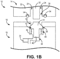
- FIG. 1B is an enlarged view of an interface between a probe and a transducer in the integrated air data sensor of FIG. 1A
- integrated air data sensor 10 is on aircraft 12 and includes probe 14, transducer 16, and faceplate 18.
- Probe 14 includes head 20, strut 21, base 22, inlet 26 of first gas path 24 at port 30, and side ports 31A-31C.
- probe 14 also includes protrusion 32 and outlet 28 of first gas path 24.
- transducer 16 includes sensors 34, second gas path 36 with inlet 38, and sealing feature 40.
- Sealing feature 40 includes plunger 42 (with plunger frustum 44 and cylinder 46) and resilient member 48. Faceplate 18 includes opening 50 and flange 52. O-ring 54 is a seal between probe 14 and faceplate 18 (or transducer 16 if faceplate 18 is not present).
- integrated air data sensor 10 is utilized on aircraft 12 and can determine environmental conditions such as static pressure or impact pressure as well as other information, such as speed and orientation of the aircraft.
- the entire system as shown in FIG. 1A is disclosed herein as integrated air data sensor 10, while individual sensors as subcomponents of integrated air data sensor 10 are disclosed as sensors 34.
- transducer 16 is housed within a fuselage of aircraft 12 while probe 14 is outside the fuselage and exposed to environmental conditions. Faceplate 18 can form the interface between probe 14 and transducer 16 to protect transducer 16.
- integrated air data sensor 10 is described in this disclosure as being utilized on aircraft 12, integrated air data sensor 10 can be utilized anywhere and/or on any vehicle to measure and record environmental conditions and/or collect other information.
- a data measurement and collection system can include multiple integrated air data sensors 10 working together (or having redundant systems), and integrated air data sensor 10 can interact with and convey information to other systems on aircraft 12, another vehicle/system in which integrated air data sensor 10 is a part, or to systems remote from integrated air data sensor 10.
- integrated air data sensor 10 can include other components not expressly described in this disclosure.
- Probe 14 is configured to be exposed to the environment and includes components for conveying environmental air to sensors 34 in transducer 16.
- probe 14 is shown with a substantially cylindrical head 20 and an elongated rectangular strut 21, and a flat rectangular base 22 perpendicular to strut 21.
- probe 14 can have other configurations suitable to convey environmental air to transducer 16.
- Probe 14 can include various attachment features that allow for probe 14 to be attached to and detached from transducer 16 (and/or faceplate 18 covering transducer 16), such as screws, bolts, glue, welds, braze, or other means. As shown, probe 14 is attached to transducer 16 at base 22 by bolts.
- Head 20 of probe 14 can be substantially cylindrical with a frustoconical tip. Head 20 includes port 30 at the tip and side ports (31A-31C) being in the sides of head 20 and forming an inlet to other gas paths that may be similar to or different from first gas path 24. Port 30 is an opening/orifice that extends from a surface of head 20 into an interior of head 20 and forms inlet 26 to first gas path 24.
- First gas path 24 is a channel extending through probe 14 between inlet 26 in head 20 and outlet 28 in base 22. First gas path 24 conveys environmental conditions, such as air with a pressure of the atmosphere in which probe 14 is located, to transducer 16 and, more particularly, to second gas path 36 (which in turn conveys environmental air to sensors 34).
- probe 14 is shown as only having one first gas path 24, probe 14 can be configured to have multiple gas paths that convey environmental air to multiple sensors 34 in transducer 16 (and therefore, integrated air data sensor 10 can include multiple interfaces having multiple protrusions 32 corresponding to multiple sealing features 40).
- Strut 21 and base 22 provide structural support to head 20 and are configured to connect probe 14 to transducer 16 and/or faceplate 18.
- Strut 21 can have any shape but, as shown in FIG. 1A , is an elongated, substantially rectangular shape that is thicker in the middle and gradually reduces thickness at both front and rear ends to be more aerodynamic.
- Strut 21 includes a portion of first gas path 24 extending through strut 21 between head 20 and base 22.
- Base 22 can be a flange with mounting features to allow for probe 14 to be attached to and detachable from transducer 16 and includes a portion of first gas path 24.
- base 22 can have various grooves or other features to allow for probe 14 to be sealed to transducer 16 and/or faceplate 18, such as a groove to accommodate O-ring 54 (as shown in FIG. 1B ).
- Base 22 includes protrusion 32 that extends away from base 22 at a location adjacent outlet 28 of first gas path 24 to interact with sealing feature 40 of transducer 16.
- Protrusion 32 is a projection adjacent to first gas path 24 and, as shown in FIG. 1A , can be located within first gas path 24.
- Other configurations of protrusion 32 can have protrusion 32 located abutting a wall of first gas path 24 or otherwise incorporated into base 22.
- Protrusion 32 can have any cross-sectional shape, such as circular (so that protrusion 32 is a cylinder).
- Protrusion 32 can extend away from base 22 any length, but should be sufficiently long to contact sealing feature 40 to push plunger 42 downward into an open position when base 22 is abutting transducer 16 and/or faceplate 18 to allow air to flow from first gas path 24 into second gas path 36.
- Protrusion 32 can have other sizes, shapes, and/or configurations suitable to move sealing feature 40 into the open position when probe 14 is abutting transducer 16 and/or faceplate 18.
- Transducer 16 is configured to mate with base 22 of probe 14 and, as shown in FIG. 1A , can be a cylindrical shape that includes second gas path 36, at least one sensor 34, and sealing feature 40.
- Transducer 16 can include other components, such as a controller that includes a computer processor capable of recording and analyzing information measured by sensor 34 (as well as other functions).
- Transducer 16 can be located within and protected from the environment by a fuselage of aircraft 12 with faceplate 18 providing a protective covering to transducer 16 and being situated between base 22 and transducer 16.
- Second gas path 36 extends at least partially through transducer 16 from inlet 38 at least to sensors 34. When probe 14 is attached to transducer 16, second gas path 36 is in fluid communication with outlet 28 of first gas path 24.
- Second gas path 36 conveys environmental air from first gas path 24 in probe 14 to sensor 34.
- Second gas path 36 can have any cross-sectional shape and, depending on sealing feature 40, can have configurations suited to seal with sealing feature 40 to prevent air and contaminants from entering second gas path 36 when probe 14 is not abutting transducer 16 and/or faceplate 18 (i.e., when sealing feature 40 is in a closed position). While transducer 16 is shown as only having one second gas path 36, transducer 16 can be configured to have multiple gas paths that convey environmental air to multiple sensors 34. Further, transducer 16 can have other configurations that are not expressly disclosed.
- Sensors 34 can be within transducer 16 and are located along second gas path 36.
- Transducer 16 can include more than one sensor 34 with multiple sensors located along second gas path 36 and/or along multiple gas paths extending through/into transducer 16.
- Sensors 34 are configured to measure environmental pressures which are used by transducer 16 to determine characteristics of the environment and/or aircraft 12, such as air pressure, altitude, airspeed, angle of attack, and other data of aircraft 12.
- Sealing feature 40 is at inlet 38 of second gas path 36 and is configured to move between the open position and the closed position.
- the open position occurs when probe 14 is abutting transducer 16 such that protrusion 32 is in contact with sealing feature 40 to allow air to flow from first gas path 24 into second gas path 36.
- the closed position occurs when probe 14 is not abutting transducer 16 such that protrusion 32 is distant from sealing feature 40 and sealing feature 40 is positioned to seal second gas path 36 to prevent contaminants from entering second gas path 36 in transducer 16.
- sealing feature 40 can have a variety of configurations for sealing second gas path 36 at inlet 38 while also allowing environmental air to pass through second gas path 36 to sensors 34 when probe 14 is abutting transducer 16 and/or faceplate 18.
- Sealing feature 40 includes plunger 42 within second gas path 36 adjacent inlet 38.
- Plunger 42 is configured to be moveable within second gas path 36 and can have any configuration able to seal second gas path 36 when in the closed position and allow air to flow through second gas path 36 when in the open position.
- plunger 42 includes plunger frustum 44, which is a frustoconical shaped component inlet 38 (when in the closed position), and cylinder 46, which is connected to plunger frustum 44 (downward from plunger frustum 44) and can be coaxial with second gas path 36.
- Plunger frustum 44 and walls of second gas path 36 are configured to contact one another when in the closed position to seal second gas path 36, with the walls also being configured to ensure plunger 42 remained within inlet 38 of second gas path 36 by angling inward into second gas path 36 to provide a lip that prevents resilient member 48 from pushing plunger 42 upward out of second gas path 36.
- Adjacent to cylinder 46 is resilient member 48, which can surround plunger frustum 44 and is configured to bias plunger 42 into the closed position by pushing on a bottom side of plunger frustum 44.
- Resilient member 48 is also able to be compressed when plunger frustum 44 is pushed by protrusion 32 downward into the open position in which plunger frustum 44 is not in contact with the lip of the walls of second gas path 36 and air is able to flow around plunger 42 and through second gas path 36.
- Resilient member 48 can be any expandable component that is able to bias plunger 42 upwards to contact the walls of second gas path 36 to seal second gas path 36 while also being compressible to allow for downward movement of plunger 42 when plunger 42 is pushed upon by protrusion 32. As shown in FIG. 1B , resilient member 48 is a spring.
- Integrated air data sensor 10 can include faceplate 18 between probe 14 and transducer 16 to provide a protective covering for transducer 16.
- Faceplate 18 can be made from a variety of materials suitable for withstanding the environment.
- Faceplate 18 includes opening 50 that is coaxial with inlet 38 of second gas path 36 and outlet 28 of first gas path 24 (when probe 14 is abutting transducer 16 and/or faceplate 18).
- Faceplate 18 can be fastened to transducer through a variety of means, including screws, bolts, welds, braze, glue, or another fastener.
- Faceplate 18 can also include flange 52 that allows for faceplate 18 to be fastened to aircraft 10.
- sealing feature 40 with plunger 42 as shown in FIG. 1B is configured to be biased upward by resilient member 48 to the closed position to seal inlet 38 of second gas path 36 when probe 14 (and protrusion 32) are not abutting transducer 16, and plunger 42 is configured to be pushed downward by protrusion 32 into the open position to allow air to flow from first gas path 24 into second gas path 36 (between the walls of second gas path 36 and plunger 42) when probe 14 is abutting transducer 16.
- integrated air data sensor 10 can include other configurations of sealing feature 40.
- FIG. 2 is an enlarged view of another embodiment of the interface between a probe and transducer in the integrated air data sensor.
- Integrated air data sensor 110 includes probe 114 having base 122, first gas path 124 with outlet 128, and protrusion 132.
- Integrated air data sensor 110 also includes transducer 116 having sensors 134, second gas path 136, and sealing feature 140 with flap 156, hinge 158, and resilient member 148.
- Integrated air data sensor 110 can also include faceplate 118 having opening 150 and flange 52.
- O-ring 154 can be between probe 114 and faceplate 118. Except for sealing feature 140 (and possibly protrusion 132), the components of integrated air data sensor 110 are similar in functionality and configuration to those of integrated air data sensor 10 in FIGS. 1A and 1B .
- Sealing feature 140 is configured to move between a closed position and an open position.
- the closed position occurs when probe 114 is not abutting transducer 116 and/or faceplate 118 (so protrusion 132 is distant from flap 156) such that flap 156 extends horizontally across inlet 138 of second gas path 136 to seal second gas path 136 by preventing air and contaminants from flowing into second gas path 136.
- the open position occurs when probe 114 is abutting transducer 116 and/or faceplate 118 such that protrusion 132 pushes flap 156 downward to allow air to flow into second gas path 136 from first gas path 124.
- flap 156 pivots about hinge 158, which is connected to a wall/side of second gas path 136.
- flap 156 is biased into the closed/horizontal position by resilient member 148, which abuts flap 156.
- Resilient member 148 can be a spring that is expandable to push flap 156 into the closed position while also being compressible to allow for flap 156 to pivot into the open position when pushed by protrusion 132.
- Protrusion 132 can be any size, shape, location, and/or orientation suitable to push flap 156 into the open position when probe 114 is abutting transducer 116 and/or faceplate 118 to allow for air to flow into second gas path 136 from first gas path 124.
- Flap 156 can have a cross-sectional shape that matches a cross-sectional shape of inlet 138 of second gas path 136 (or opening 150 of faceplate 118 if flap 156 and hinge 158 are located within opening 150).
- flap 156 and second gas path 136 at inlet 138 both have a cross-sectional shape that is a circle.
- Hinge 158 can have any configuration that allows flap 156 to pivot between the open and closed positions, such as a pin extending through clasps.
- FIG. 3 is an enlarged view of a third embodiment of the interface between a probe and transducer in the integrated air data sensor.
- Integrated air data sensor 210 includes probe 214 having base 222, first gas path 224 with outlet 228, and protrusion 232.
- Integrated air data sensor 210 also includes transducer 216 having sensors 234, second gas path 236, and sealing feature 240 with butterfly valve 240 (which has disk 262 and pin 264).
- O-ring 254 can be between probe 214 and transducer 216. Except for sealing feature 240 and protrusion 232, the components of integrated air data sensor 210 are similar in functionality and configuration to those of integrated air data sensor 10 in FIGS. 1A and 1B .
- Sealing feature 240 is configured to move between a closed position and an open position.
- the closed position occurs when probe 214 is not abutting transducer 216 (so protrusion 232 is distant from disk 262) such that disk 262 of butterfly valve 240 extends horizontally across inlet 238 of second gas path 236 to seal second gas path 236 by preventing air and contaminants from flowing into second gas path 236.
- the open position occurs when probe 214 is abutting transducer 216 such that protrusion 232 pushes disk 262 of butterfly valve 240 to pivot about pin 264 so disk 262 is no longer horizontal to allow air to flow into second gas path 236 from first gas path 224.
- disk 262 pivots about pin 264, which is connected to at least one wall/side of second gas path 236.
- disk 262 of butterfly valve 240 is biased into the closed/horizontal position by resilient member 248, which abuts disk 262.
- Resilient member 248 can be a spring that is expandable to push disk 262 into the closed position while also being compressible to allow for disk 262 to pivot into the open position when pushed by protrusion 232.
- Protrusion 232 can be any size, shape, location, and/or orientation suitable to push disk 262 into the open position when probe 214 is abutting transducer 216 to allow for air to flow into second gas path 236 from first gas path 224. As shown in FIG.
- protrusion 232 does not extend about a center of first gas path 224 and instead is connected to a side of first gas path 224 so protrusion 232 contacts and pushes disk 262 without contacting pin 264.
- Disk 262 of butterfly valve 240 can have a cross-sectional shape that matches a cross-sectional shape of inlet 238 of second gas path 236.
- Disk 262 and pin 264 can have any configuration that allows for butterfly valve to pivot between the open and closed positions, such as a pin that extends through clasps or another configuration.
- Integrated air data sensor 10/110/210 includes probe 14/114/214 that is detachable from transducer 16/116/216 such that, when probe 14/114/214 has been damaged or is malfunctioning, probe 14/114/214 can be easily swapped out for an undamaged, functioning probe 14/114/214.
- Integrated air data sensor 10/110/210 also includes sealing feature 40/140/240 of transducer 16/116/216, which prevents contaminants from entering second gas path 36/136/236 of transducer 16/116/216 when probe 14/114/214 is detached from transducer 16/116/216.
- the disclosed integrated air data sensor 10/110/210 both allows for replacement of probe 14/114/214, and implores measurement accuracy by preventing contaminants from entering transducer 16/116/216.
- Integrated air data sensor 10/110/210 allowing for replacement of probe 14/114/214 without having to replace the entire integrated air data sensor 10/110/210 reduces cost and downtime because the replacement of probe 14/114/214 can be done without the need for aircraft 12 to go into a maintenance hangar or otherwise be taken out of operation.
Landscapes
- Engineering & Computer Science (AREA)
- Aviation & Aerospace Engineering (AREA)
- Physics & Mathematics (AREA)
- General Physics & Mathematics (AREA)
- Indicating Or Recording The Presence, Absence, Or Direction Of Movement (AREA)
- Investigating Or Analyzing Materials By The Use Of Ultrasonic Waves (AREA)
Claims (14)
- Integrierter Luftdatensensor (10, 110, 210), umfassend:einen Wandler (16, 116, 216); undeine Sonde (14, 114, 214), die mit dem Wandler (16, 116, 216) durch ein Dichtungsmerkmal (40, 140, 240) derart wirkverbunden werden kann, dass ein durch die Sonde (14, 114, 214) definierter erster Gasweg (24, 124, 224) fluidisch an einen durch den Wandler (16, 116) definierten zweiten Gasweg (36, 136, 236) über einen Einlass (38, 138, 238) zu dem zweiten Gasweg (36, 136, 236) gekoppelt ist, wenn sich das Dichtungsmerkmal (40, 140, 240) in einer offenen Position befindet, und der Einlass (38, 138, 238) für einen Fluidstrom dort hindurch blockiert ist, wenn sich das Dichtungsmerkmal (40, 140, 240) in einer geschlossenen Position befindet;wobei das Dichtungsmerkmal (40, 140, 240) dazu konfiguriert ist, sich aus der offenen Position in die geschlossene Position zu bewegen, wenn die Sonde (14, 114, 214) von dem Wandler (16, 116, 216) abgenommen wird.
- Integrierter Luftdatensensor (10) nach Anspruch 1, wobei das Dichtungsmerkmal (40) ferner Folgendes umfasst:einen Kolben (42) innerhalb des zweiten Gasweges (36) benachbart zu dem Einlass (38) zu dem zweiten Gasweg (36);ein elastisches Element (48), das an dem Kolben (42) anliegt, wobei das elastische Element (48) dazu konfiguriert ist, den Kolben (42) in die geschlossene Position vorzuspannen, in welcher der Kolben (42) verhindert, dass Verunreinigungen in den zweiten Gasweg (36) gelangen; undeinen Vorsprung (32) benachbart zu einem Auslass (26) zu dem ersten Gasweg (24),wobei, wenn die Sonde (14) an dem Wandler (16) anliegt, der Vorsprung (32) den Kolben (42) in die offene Position drückt, sodass Luft an dem Kolben (42) vorbei und in den zweiten Gasweg (36) strömen kann.
- Integrierter Luftdatensensor (10) nach Anspruch 2, wobei der Kolben (42) einen kegelstumpfförmigen Abschnitt (44) beinhaltet, der sich nach außen erstreckt, um mit Seiten des zweiten Gasweges (36) in Kontakt zu stehen, wenn sich der Kolben (42) in der geschlossenen Position befindet.
- Integrierter Luftdatensensor (10) nach Anspruch 3, wobei der Kolben (42) einen zylindrischen Abschnitt (46) beinhaltet, der mit dem kegelstumpfförmigen Abschnitt (44) verbunden ist und koaxial zu dem zweiten Gasweg (36) verläuft, wobei der zylindrische Abschnitt (46) zu dem elastischen Element (48) benachbart ist.
- Integrierter Luftdatensensor (10) nach Anspruch 2,3 oder 4, wobei es sich bei dem elastischen Element (40) um eine Feder handelt.
- Integrierter Luftdatensensor (110) nach Anspruch 1, wobei das Dichtungsmerkmal (140) ferner Folgendes umfasst:eine Klappe (156) benachbart zu dem Einlass (138) zu dem zweiten Gasweg (136);ein Scharnier (158), das die Klappe (156) mit einer Seite des zweiten Gasweges (136) verbindet; undein elastisches Element (148), das an der Klappe (156) anliegt, wobei das elastische Element (148) dazu konfiguriert ist, die Klappe (156) in die geschlossene Position vorzuspannen, sodass die Klappe (156) verhindert, dass Luft und Verunreinigungen in den zweiten Gasweg (136) gelangen,wobei, wenn die Sonde (114) benachbart zu dem Wandler (116) ist, ein Vorsprung (132) die Klappe (156) in die offene Position drückt, sodass Luft an der Klappe (156) vorbei und in den zweiten Gasweg (136) strömen kann.
- Integrierter Luftdatensensor (110) nach Anspruch 6, wobei eine Querschnittsform des zweiten Gasweges (136) an dem Einlass (138) ein Kreis ist und eine Querschnittsform der Klappe (156) ein Kreis ist.
- Integrierter Luftdatensensor (210) nach Anspruch 1, wobei das Dichtungsmerkmal (240) ferner Folgendes umfasst:eine Absperrklappe (240) benachbart zu dem Einlass (238) zu dem zweiten Gasweg (236), wobei die Absperrklappe (240) eine Scheibe (262), die einer Querschnittsform des zweiten Gasweges (236) entspricht, und einen Stift (264) aufweist, der einen Drehzapfen bildet, um den sich die Scheibe (262) dreht; undein elastisches Element (248), das an der Scheibe (262) anliegt, wobei das elastische Element (248) dazu konfiguriert ist, die Scheibe (262) in die geschlossene Position vorzuspannen, in der die Absperrklappe (240) verhindert, dass Verunreinigungen in den zweiten Gasweg (236) gelangen,wobei, wenn die Sonde (214) benachbart zu dem Wandler (216) ist, ein Vorsprung (232) die Scheibe (262) der Absperrklappe (240) in die offenen Position drückt, sodass Luft an der Scheibe (262) vorbei und in den zweiten Gasweg (236) strömen kann.
- Luftfahrzeug (12), umfassend den integrierten Luftdatensensor (10, 110, 210) nach einem der vorhergehenden Ansprüche.
- Luftfahrzeug (12) nach Anspruch 9, wobei die Sonde (14, 114, 214) der Umgebung ausgesetzt ist und sich der Wandler innerhalb eines Rumpfes des Luftfahrzeugs (12) befindet.
- System, umfassend einen integrierten Luftdatensensor (10, 110, 210) nach einem der Ansprüche 1-10:wobei die Sonde (16, 116, 216) abnehmbar ist, undsich der erste Gasweg (24, 124, 224) durch die Sonde (16, 116, 216) erstreckt;wobei die Sonde (16, 116, 216) ferner Folgendes umfasst:einen Kopf (20) mit einem Anschluss, der den Einlass zu dem ersten Gasweg (24, 124, 224) bildet; undeine Halterung (21, 22), die den Auslass (28, 238, 228) des ersten Gasweges (24, 124, 224) und einen Vorsprung (32, 132, 232) umfasst, der sich von der Halterung (21, 22) weg an einer Stelle benachbart zu dem Auslass (28, 238, 228) erstreckt; undwobei der Wandler (14, 114, 214) dazu konfiguriert ist, mit der Halterung (21, 22) zusammenzupassen,und der zweite Gasweg (36, 136, 236) mit dem Einlass (38, 138, 238) dazu konfiguriert ist, in Fluidkommunikation mit dem Auslass (28, 238, 228) des ersten Gasweges (24, 124, 224) zu stehen, wenn der Wandler (14, 114, 214) mit der Halterung (21, 22) zusammengepasst wird;wobei der Wandler (14, 114, 214) ferner Folgendes umfasst:mindestens einen Sensor (34), der entlang des zweiten Gasweges (36, 136, 236) angeordnet ist; undwobei das Dichtungsmerkmal (40, 140, 240) benachbart zu dem Einlass (38, 138, 238) des zweiten Gasweges (36, 136, 236) angeordnet ist,wobei, wenn die Halterung (21, 22) der Sonde (16, 116, 216) benachbart zu dem Wandler (14, 114, 214) ist, der Vorsprung mit dem Dichtungsmerkmal (14, 140, 240) interagiert, sodass sich das Dichtungsmerkmal (14, 140, 240) in einer offenen Position befindet, um zu ermöglichen, dass Luft aus dem ersten Gasweg (24, 124, 224) in den zweiten Gasweg (36, 136, 236) strömt, und wenn die Halterung (21, 22) der Sonde (16, 116, 216) von dem Wandler (14, 114, 214) beabstandet ist, sich das Dichtungsmerkmal (40, 140, 240) in einer geschlossenen Position befindet, um zu verhindern, dass Verunreinigungen in den zweiten Gasweg (36, 136, 236) gelangen.
- System nach Anspruch 11, wobei der erste Gasweg (24, 124, 224) eine kreisförmige Querschnittsform an dem Auslass (28, 128, 228) aufweist und sich der Vorsprung innerhalb des ersten Gasweges (24, 124, 224) befindet und sich von dem Auslass (28, 128, 228) des ersten Gasweges (24, 124, 224) nach außen erstreckt.
- Verfahren zum Schützen eines Gasweges eines Wandlers (14, 114, 214) des integrierten Luftdatensensors (10, 110, 210) nach Anspruch 1, wenn die Sonde (16, 116, 216) des integrierten Luftdatensensors (10, 110, 210) entfernt wird, wobei das Verfahren Folgendes umfasst:
Abnehmen der Sonde (16, 116, 216) von dem Wandler (14, 114, 214), wobei die Sonde (16, 116, 216) den ersten Gasweg (24, 124, 224) definiert, der über einen Einlass (38, 138, 238) des zweiten Gasweges (36, 136, 236) in Fluidkommunikation mit dem durch den Wandler (14, 114,214) definierten zweiten Gasweg (36, 136, 236) steht, wenn die Sonde (16, 116, 216) an dem Wandler (14, 114, 214) angebracht ist, und als Reaktion auf das Abnehmen der Sonde (16, 116, 216) der Einlass (38, 138, 238) des zweiten Gasweges (36, 136, 236) abgedichtet wird. - Verfahren nach Anspruch 13, wobei das Abdichten des Einlasses des Wandlers (14, 114, 214) ferner Folgendes umfasst:Vorspannen eines Kolbens (42) eines Dichtungsmerkmals (40) an dem Einlass (38) zu dem zweiten Gasweg (36) in eine geschlossene Position unter Verwendung eines elastischen Elements (48), das an dem Kolben (42) anliegt, oderDrehen einer Klappe (156) eines Dichtungselements (140) an dem Einlass (38, 138, 238) zu dem zweiten Gasweg (136) um ein Scharnier (158), das die Klappe (156) mit einer Seite des zweiten Gasweges (136) verbindet, in eine geschlossene Position, oderDrehen einer Absperrklappe (240) eines Dichtungsmerkmals an dem Einlass (238) zu dem zweiten Gasweg (236) um einen Drehzapfen in eine geschlossene Position.
Applications Claiming Priority (1)
| Application Number | Priority Date | Filing Date | Title |
|---|---|---|---|
| US16/009,780 US10739372B2 (en) | 2018-06-15 | 2018-06-15 | Detachable probe and sealing of an integrated air data sensor |
Publications (2)
| Publication Number | Publication Date |
|---|---|
| EP3581940A1 EP3581940A1 (de) | 2019-12-18 |
| EP3581940B1 true EP3581940B1 (de) | 2021-01-06 |
Family
ID=66912746
Family Applications (1)
| Application Number | Title | Priority Date | Filing Date |
|---|---|---|---|
| EP19180636.3A Active EP3581940B1 (de) | 2018-06-15 | 2019-06-17 | Abnehmbare sonde und abdichtung eines integrierten luftdatensensors |
Country Status (3)
| Country | Link |
|---|---|
| US (1) | US10739372B2 (de) |
| EP (1) | EP3581940B1 (de) |
| CA (1) | CA3045319A1 (de) |
Families Citing this family (3)
| Publication number | Priority date | Publication date | Assignee | Title |
|---|---|---|---|---|
| CN113983172B (zh) * | 2021-09-18 | 2024-04-26 | 太原航空仪表有限公司 | 一种l形受压器的旋转对接式密封装置 |
| US12320825B2 (en) | 2022-08-11 | 2025-06-03 | Rosemount Aerospace Inc. | Probe blockage detection and removal |
| CN118603678B (zh) * | 2024-08-07 | 2024-11-01 | 成都信息工程大学 | 一种高空大气监测系统 |
Family Cites Families (19)
| Publication number | Priority date | Publication date | Assignee | Title |
|---|---|---|---|---|
| US2488810A (en) | 1946-05-25 | 1949-11-22 | Easterday Karl | Automatic shutter mechanism for pitot tubes |
| US5639964A (en) | 1994-10-24 | 1997-06-17 | Djorup; Robert S. | Thermal anemometer airstream turbulent energy detector |
| US6622390B2 (en) | 2001-08-29 | 2003-09-23 | Rosemount Aerospace Inc. | Method and apparatus for installation and alignment of air data sensing probe |
| US6761057B2 (en) | 2001-09-13 | 2004-07-13 | Rosemount Aerospace Inc. | Error detection and fault isolation for multi-function air data probes and systems |
| US7490510B2 (en) | 2005-10-24 | 2009-02-17 | Ametek, Inc. | Multi-function air data sensor |
| CA2535577C (en) | 2006-02-08 | 2013-08-13 | Nav-Aids Ltee | Test adapter for aircraft static vent |
| US20120008882A1 (en) | 2009-04-01 | 2012-01-12 | Hewlett-Packard Development Company Lp | Fluid handling system |
| US8930062B2 (en) | 2009-04-21 | 2015-01-06 | Indian Space Research Organisation | System and method for detecting and isolating faults in pressure sensing of flush air data system (FADS) |
| DE102011110061A1 (de) | 2011-08-12 | 2013-02-14 | Rheinische Friedrich-Wilhelms-Universität Bonn | Messvorrichtung und Verfahren zur Bestimmung von räumlich-zeitlichen Druckschwankungsmustern innerhalb eines Fluids |
| WO2013028220A1 (en) | 2011-08-19 | 2013-02-28 | Aerovironment Inc. | Water resisitant aircraft pitot device |
| FR2993357A1 (fr) | 2013-01-09 | 2014-01-17 | Airbus Operations Sas | Systeme de fixation d'une sonde de mesure de pression statique sur un aeronef. |
| US9366555B2 (en) | 2013-12-18 | 2016-06-14 | Lockheed Martin Corporation | Air data system |
| DE102014010293B4 (de) | 2014-07-11 | 2019-10-31 | Airbus Defence and Space GmbH | Druckanschluss für ein Luftfahrzeug |
| CN104386256B (zh) | 2014-10-24 | 2016-08-24 | 太原航空仪表有限公司 | 全静压受感器折叠装置 |
| US9909905B2 (en) * | 2015-10-15 | 2018-03-06 | Honeywell International Inc. | Multi-part air data probe assembly to facilitate rapid replacement |
| CN205262673U (zh) | 2015-12-23 | 2016-05-25 | 太原航空仪表有限公司 | 一种空速管静压测试装置 |
| CN106018866A (zh) | 2016-08-05 | 2016-10-12 | 北京奇正数元科技股份有限公司 | 一体式快拆空速计 |
| US10184953B2 (en) | 2016-08-08 | 2019-01-22 | Cobra Systems, Inc. | Pitot-static anemometric test adapter |
| CN205982315U (zh) | 2016-08-15 | 2017-02-22 | 中国海诚工程科技股份有限公司 | 皮托管测量孔的密封装置 |
-
2018
- 2018-06-15 US US16/009,780 patent/US10739372B2/en active Active
-
2019
- 2019-06-05 CA CA3045319A patent/CA3045319A1/en active Pending
- 2019-06-17 EP EP19180636.3A patent/EP3581940B1/de active Active
Non-Patent Citations (1)
| Title |
|---|
| None * |
Also Published As
| Publication number | Publication date |
|---|---|
| EP3581940A1 (de) | 2019-12-18 |
| CA3045319A1 (en) | 2019-12-15 |
| US20190383849A1 (en) | 2019-12-19 |
| US10739372B2 (en) | 2020-08-11 |
| BR102019009742A2 (pt) | 2019-12-17 |
Similar Documents
| Publication | Publication Date | Title |
|---|---|---|
| EP3581940A1 (de) | Abnehmbare sonde und abdichtung eines integrierten luftdatensensors | |
| CA2739271C (en) | Device for checking a flow pressure measurement probe, and probe comprising the device | |
| US8961634B2 (en) | Filter systems for air intakes of aircraft engines and related methods | |
| US10495662B2 (en) | Multifunction probe for primary references for aircraft, associated measuring system, aircraft and method for obtaining physical quantities | |
| US8100022B2 (en) | Device for measuring the total pressure of a flow and method implementing the device | |
| EP2453245A1 (de) | System und Verfahren zur Detektion von blockierten Pitot-Statik-Anschlüssen | |
| JP5309276B2 (ja) | 自動的なゼロ点校正及びフラッシングを備えた、差圧センサーのバルブアセンブリ | |
| EP3290342A1 (de) | Verfahren zur modifizierung von turbomotorbetriebsgrenzen | |
| EP3567379B1 (de) | Statische pitot-sonde mit pneumatischem anstellwinkelsensor | |
| US11117677B2 (en) | Aircraft filter system with airspeed compensation | |
| CN104949795B (zh) | 使高维护空气数据系统部件共同位于一个lru内 | |
| EP3581941B1 (de) | Abnehmbare sonde und abdichtung eines integrierten luftdatensensors | |
| CA2879842C (en) | Boundary layer flow sensor | |
| CA2343622C (en) | Device for pressure tapping and procedure for setting it on fuselage panel of an aircraft | |
| JP2016540148A (ja) | 航空機エンジンストラット組立体及びその組立方法 | |
| EP2715372B1 (de) | Luftdatensensor mit mitteln zur reinigung der pneumatischen leitungen | |
| BR102019009742B1 (pt) | Sensor de dados de ar integrado, aeronave, sistema, e, método para proteger um caminho de gás de um transdutor de um sensor de dados de ar integrado | |
| BR102019012329B1 (pt) | Sensor de dados de ar integrado, aeronave, e, sistema para aeronave | |
| EP1883789B1 (de) | Instrumentationsanordnung | |
| GB2491167A (en) | Aircraft wing blister | |
| EP4086638B1 (de) | Flugzeug-druckmessgerät | |
| US12601651B2 (en) | Probe for measuring static or parietal pressure | |
| US20250369997A1 (en) | Air data probe inspection tool | |
| KR102091618B1 (ko) | 오리피스 플레이트를 이용하여 비행체 연료 시스템의 유량을 조절하는 방법 및 장치 | |
| BR102025010377A2 (pt) | Sistema pitô, aeronave, e, método |
Legal Events
| Date | Code | Title | Description |
|---|---|---|---|
| PUAI | Public reference made under article 153(3) epc to a published international application that has entered the european phase |
Free format text: ORIGINAL CODE: 0009012 |
|
| STAA | Information on the status of an ep patent application or granted ep patent |
Free format text: STATUS: THE APPLICATION HAS BEEN PUBLISHED |
|
| AK | Designated contracting states |
Kind code of ref document: A1 Designated state(s): AL AT BE BG CH CY CZ DE DK EE ES FI FR GB GR HR HU IE IS IT LI LT LU LV MC MK MT NL NO PL PT RO RS SE SI SK SM TR |
|
| AX | Request for extension of the european patent |
Extension state: BA ME |
|
| STAA | Information on the status of an ep patent application or granted ep patent |
Free format text: STATUS: REQUEST FOR EXAMINATION WAS MADE |
|
| 17P | Request for examination filed |
Effective date: 20200611 |
|
| RBV | Designated contracting states (corrected) |
Designated state(s): AL AT BE BG CH CY CZ DE DK EE ES FI FR GB GR HR HU IE IS IT LI LT LU LV MC MK MT NL NO PL PT RO RS SE SI SK SM TR |
|
| GRAP | Despatch of communication of intention to grant a patent |
Free format text: ORIGINAL CODE: EPIDOSNIGR1 |
|
| STAA | Information on the status of an ep patent application or granted ep patent |
Free format text: STATUS: GRANT OF PATENT IS INTENDED |
|
| INTG | Intention to grant announced |
Effective date: 20200813 |
|
| GRAS | Grant fee paid |
Free format text: ORIGINAL CODE: EPIDOSNIGR3 |
|
| GRAA | (expected) grant |
Free format text: ORIGINAL CODE: 0009210 |
|
| STAA | Information on the status of an ep patent application or granted ep patent |
Free format text: STATUS: THE PATENT HAS BEEN GRANTED |
|
| AK | Designated contracting states |
Kind code of ref document: B1 Designated state(s): AL AT BE BG CH CY CZ DE DK EE ES FI FR GB GR HR HU IE IS IT LI LT LU LV MC MK MT NL NO PL PT RO RS SE SI SK SM TR |
|
| REG | Reference to a national code |
Ref country code: GB Ref legal event code: FG4D |
|
| REG | Reference to a national code |
Ref country code: AT Ref legal event code: REF Ref document number: 1352945 Country of ref document: AT Kind code of ref document: T Effective date: 20210115 Ref country code: CH Ref legal event code: EP |
|
| REG | Reference to a national code |
Ref country code: DE Ref legal event code: R096 Ref document number: 602019002064 Country of ref document: DE |
|
| REG | Reference to a national code |
Ref country code: IE Ref legal event code: FG4D |
|
| REG | Reference to a national code |
Ref country code: NL Ref legal event code: MP Effective date: 20210106 |
|
| REG | Reference to a national code |
Ref country code: AT Ref legal event code: MK05 Ref document number: 1352945 Country of ref document: AT Kind code of ref document: T Effective date: 20210106 |
|
| REG | Reference to a national code |
Ref country code: LT Ref legal event code: MG9D |
|
| PG25 | Lapsed in a contracting state [announced via postgrant information from national office to epo] |
Ref country code: LT Free format text: LAPSE BECAUSE OF FAILURE TO SUBMIT A TRANSLATION OF THE DESCRIPTION OR TO PAY THE FEE WITHIN THE PRESCRIBED TIME-LIMIT Effective date: 20210106 Ref country code: PT Free format text: LAPSE BECAUSE OF FAILURE TO SUBMIT A TRANSLATION OF THE DESCRIPTION OR TO PAY THE FEE WITHIN THE PRESCRIBED TIME-LIMIT Effective date: 20210506 Ref country code: NO Free format text: LAPSE BECAUSE OF FAILURE TO SUBMIT A TRANSLATION OF THE DESCRIPTION OR TO PAY THE FEE WITHIN THE PRESCRIBED TIME-LIMIT Effective date: 20210406 Ref country code: BG Free format text: LAPSE BECAUSE OF FAILURE TO SUBMIT A TRANSLATION OF THE DESCRIPTION OR TO PAY THE FEE WITHIN THE PRESCRIBED TIME-LIMIT Effective date: 20210406 Ref country code: HR Free format text: LAPSE BECAUSE OF FAILURE TO SUBMIT A TRANSLATION OF THE DESCRIPTION OR TO PAY THE FEE WITHIN THE PRESCRIBED TIME-LIMIT Effective date: 20210106 Ref country code: GR Free format text: LAPSE BECAUSE OF FAILURE TO SUBMIT A TRANSLATION OF THE DESCRIPTION OR TO PAY THE FEE WITHIN THE PRESCRIBED TIME-LIMIT Effective date: 20210407 Ref country code: FI Free format text: LAPSE BECAUSE OF FAILURE TO SUBMIT A TRANSLATION OF THE DESCRIPTION OR TO PAY THE FEE WITHIN THE PRESCRIBED TIME-LIMIT Effective date: 20210106 |
|
| PG25 | Lapsed in a contracting state [announced via postgrant information from national office to epo] |
Ref country code: SE Free format text: LAPSE BECAUSE OF FAILURE TO SUBMIT A TRANSLATION OF THE DESCRIPTION OR TO PAY THE FEE WITHIN THE PRESCRIBED TIME-LIMIT Effective date: 20210106 Ref country code: RS Free format text: LAPSE BECAUSE OF FAILURE TO SUBMIT A TRANSLATION OF THE DESCRIPTION OR TO PAY THE FEE WITHIN THE PRESCRIBED TIME-LIMIT Effective date: 20210106 Ref country code: AT Free format text: LAPSE BECAUSE OF FAILURE TO SUBMIT A TRANSLATION OF THE DESCRIPTION OR TO PAY THE FEE WITHIN THE PRESCRIBED TIME-LIMIT Effective date: 20210106 Ref country code: LV Free format text: LAPSE BECAUSE OF FAILURE TO SUBMIT A TRANSLATION OF THE DESCRIPTION OR TO PAY THE FEE WITHIN THE PRESCRIBED TIME-LIMIT Effective date: 20210106 Ref country code: PL Free format text: LAPSE BECAUSE OF FAILURE TO SUBMIT A TRANSLATION OF THE DESCRIPTION OR TO PAY THE FEE WITHIN THE PRESCRIBED TIME-LIMIT Effective date: 20210106 |
|
| PG25 | Lapsed in a contracting state [announced via postgrant information from national office to epo] |
Ref country code: IS Free format text: LAPSE BECAUSE OF FAILURE TO SUBMIT A TRANSLATION OF THE DESCRIPTION OR TO PAY THE FEE WITHIN THE PRESCRIBED TIME-LIMIT Effective date: 20210506 |
|
| REG | Reference to a national code |
Ref country code: DE Ref legal event code: R097 Ref document number: 602019002064 Country of ref document: DE |
|
| PG25 | Lapsed in a contracting state [announced via postgrant information from national office to epo] |
Ref country code: EE Free format text: LAPSE BECAUSE OF FAILURE TO SUBMIT A TRANSLATION OF THE DESCRIPTION OR TO PAY THE FEE WITHIN THE PRESCRIBED TIME-LIMIT Effective date: 20210106 Ref country code: CZ Free format text: LAPSE BECAUSE OF FAILURE TO SUBMIT A TRANSLATION OF THE DESCRIPTION OR TO PAY THE FEE WITHIN THE PRESCRIBED TIME-LIMIT Effective date: 20210106 Ref country code: SM Free format text: LAPSE BECAUSE OF FAILURE TO SUBMIT A TRANSLATION OF THE DESCRIPTION OR TO PAY THE FEE WITHIN THE PRESCRIBED TIME-LIMIT Effective date: 20210106 |
|
| PLBE | No opposition filed within time limit |
Free format text: ORIGINAL CODE: 0009261 |
|
| STAA | Information on the status of an ep patent application or granted ep patent |
Free format text: STATUS: NO OPPOSITION FILED WITHIN TIME LIMIT |
|
| PG25 | Lapsed in a contracting state [announced via postgrant information from national office to epo] |
Ref country code: DK Free format text: LAPSE BECAUSE OF FAILURE TO SUBMIT A TRANSLATION OF THE DESCRIPTION OR TO PAY THE FEE WITHIN THE PRESCRIBED TIME-LIMIT Effective date: 20210106 Ref country code: RO Free format text: LAPSE BECAUSE OF FAILURE TO SUBMIT A TRANSLATION OF THE DESCRIPTION OR TO PAY THE FEE WITHIN THE PRESCRIBED TIME-LIMIT Effective date: 20210106 Ref country code: SK Free format text: LAPSE BECAUSE OF FAILURE TO SUBMIT A TRANSLATION OF THE DESCRIPTION OR TO PAY THE FEE WITHIN THE PRESCRIBED TIME-LIMIT Effective date: 20210106 |
|
| 26N | No opposition filed |
Effective date: 20211007 |
|
| PG25 | Lapsed in a contracting state [announced via postgrant information from national office to epo] |
Ref country code: ES Free format text: LAPSE BECAUSE OF FAILURE TO SUBMIT A TRANSLATION OF THE DESCRIPTION OR TO PAY THE FEE WITHIN THE PRESCRIBED TIME-LIMIT Effective date: 20210106 Ref country code: AL Free format text: LAPSE BECAUSE OF FAILURE TO SUBMIT A TRANSLATION OF THE DESCRIPTION OR TO PAY THE FEE WITHIN THE PRESCRIBED TIME-LIMIT Effective date: 20210106 Ref country code: MC Free format text: LAPSE BECAUSE OF FAILURE TO SUBMIT A TRANSLATION OF THE DESCRIPTION OR TO PAY THE FEE WITHIN THE PRESCRIBED TIME-LIMIT Effective date: 20210106 |
|
| PG25 | Lapsed in a contracting state [announced via postgrant information from national office to epo] |
Ref country code: SI Free format text: LAPSE BECAUSE OF FAILURE TO SUBMIT A TRANSLATION OF THE DESCRIPTION OR TO PAY THE FEE WITHIN THE PRESCRIBED TIME-LIMIT Effective date: 20210106 |
|
| REG | Reference to a national code |
Ref country code: BE Ref legal event code: MM Effective date: 20210630 |
|
| PG25 | Lapsed in a contracting state [announced via postgrant information from national office to epo] |
Ref country code: LU Free format text: LAPSE BECAUSE OF NON-PAYMENT OF DUE FEES Effective date: 20210617 |
|
| PG25 | Lapsed in a contracting state [announced via postgrant information from national office to epo] |
Ref country code: IT Free format text: LAPSE BECAUSE OF FAILURE TO SUBMIT A TRANSLATION OF THE DESCRIPTION OR TO PAY THE FEE WITHIN THE PRESCRIBED TIME-LIMIT Effective date: 20210106 Ref country code: IE Free format text: LAPSE BECAUSE OF NON-PAYMENT OF DUE FEES Effective date: 20210617 |
|
| PG25 | Lapsed in a contracting state [announced via postgrant information from national office to epo] |
Ref country code: IS Free format text: LAPSE BECAUSE OF FAILURE TO SUBMIT A TRANSLATION OF THE DESCRIPTION OR TO PAY THE FEE WITHIN THE PRESCRIBED TIME-LIMIT Effective date: 20210506 |
|
| PG25 | Lapsed in a contracting state [announced via postgrant information from national office to epo] |
Ref country code: BE Free format text: LAPSE BECAUSE OF NON-PAYMENT OF DUE FEES Effective date: 20210630 |
|
| REG | Reference to a national code |
Ref country code: CH Ref legal event code: PL |
|
| PG25 | Lapsed in a contracting state [announced via postgrant information from national office to epo] |
Ref country code: LI Free format text: LAPSE BECAUSE OF NON-PAYMENT OF DUE FEES Effective date: 20220630 Ref country code: CH Free format text: LAPSE BECAUSE OF NON-PAYMENT OF DUE FEES Effective date: 20220630 |
|
| PG25 | Lapsed in a contracting state [announced via postgrant information from national office to epo] |
Ref country code: NL Free format text: LAPSE BECAUSE OF NON-PAYMENT OF DUE FEES Effective date: 20210206 Ref country code: CY Free format text: LAPSE BECAUSE OF FAILURE TO SUBMIT A TRANSLATION OF THE DESCRIPTION OR TO PAY THE FEE WITHIN THE PRESCRIBED TIME-LIMIT Effective date: 20210106 |
|
| PG25 | Lapsed in a contracting state [announced via postgrant information from national office to epo] |
Ref country code: HU Free format text: LAPSE BECAUSE OF FAILURE TO SUBMIT A TRANSLATION OF THE DESCRIPTION OR TO PAY THE FEE WITHIN THE PRESCRIBED TIME-LIMIT; INVALID AB INITIO Effective date: 20190617 |
|
| PG25 | Lapsed in a contracting state [announced via postgrant information from national office to epo] |
Ref country code: MK Free format text: LAPSE BECAUSE OF FAILURE TO SUBMIT A TRANSLATION OF THE DESCRIPTION OR TO PAY THE FEE WITHIN THE PRESCRIBED TIME-LIMIT Effective date: 20210106 |
|
| PG25 | Lapsed in a contracting state [announced via postgrant information from national office to epo] |
Ref country code: TR Free format text: LAPSE BECAUSE OF FAILURE TO SUBMIT A TRANSLATION OF THE DESCRIPTION OR TO PAY THE FEE WITHIN THE PRESCRIBED TIME-LIMIT Effective date: 20210106 |
|
| PG25 | Lapsed in a contracting state [announced via postgrant information from national office to epo] |
Ref country code: MT Free format text: LAPSE BECAUSE OF FAILURE TO SUBMIT A TRANSLATION OF THE DESCRIPTION OR TO PAY THE FEE WITHIN THE PRESCRIBED TIME-LIMIT Effective date: 20210106 |
|
| PGFP | Annual fee paid to national office [announced via postgrant information from national office to epo] |
Ref country code: DE Payment date: 20250520 Year of fee payment: 7 |
|
| PGFP | Annual fee paid to national office [announced via postgrant information from national office to epo] |
Ref country code: GB Payment date: 20250520 Year of fee payment: 7 |
|
| PGFP | Annual fee paid to national office [announced via postgrant information from national office to epo] |
Ref country code: FR Payment date: 20250520 Year of fee payment: 7 |
|
| P01 | Opt-out of the competence of the unified patent court (upc) registered |
Free format text: CASE NUMBER: UPC_APP_0018012_3581940/2025 Effective date: 20251217 |