EP3582090B1 - Datenerfassungsvorrichtung zur auflage auf eine berührungsempfindliche platte eines endgeräts, entsprechendes datenerfassungverfahren und -system - Google Patents
Datenerfassungsvorrichtung zur auflage auf eine berührungsempfindliche platte eines endgeräts, entsprechendes datenerfassungverfahren und -system Download PDFInfo
- Publication number
- EP3582090B1 EP3582090B1 EP19179642.4A EP19179642A EP3582090B1 EP 3582090 B1 EP3582090 B1 EP 3582090B1 EP 19179642 A EP19179642 A EP 19179642A EP 3582090 B1 EP3582090 B1 EP 3582090B1
- Authority
- EP
- European Patent Office
- Prior art keywords
- network
- conductive tracks
- touch screen
- capacitance
- contact
- Prior art date
- Legal status (The legal status is an assumption and is not a legal conclusion. Google has not performed a legal analysis and makes no representation as to the accuracy of the status listed.)
- Active
Links
Images

Classifications
-
- G—PHYSICS
- G06—COMPUTING OR CALCULATING; COUNTING
- G06F—ELECTRIC DIGITAL DATA PROCESSING
- G06F3/00—Input arrangements for transferring data to be processed into a form capable of being handled by the computer; Output arrangements for transferring data from processing unit to output unit, e.g. interface arrangements
- G06F3/01—Input arrangements or combined input and output arrangements for interaction between user and computer
- G06F3/03—Arrangements for converting the position or the displacement of a member into a coded form
- G06F3/041—Digitisers, e.g. for touch screens or touch pads, characterised by the transducing means
- G06F3/044—Digitisers, e.g. for touch screens or touch pads, characterised by the transducing means by capacitive means
- G06F3/0446—Digitisers, e.g. for touch screens or touch pads, characterised by the transducing means by capacitive means using a grid-like structure of electrodes in at least two directions, e.g. using row and column electrodes
-
- G—PHYSICS
- G06—COMPUTING OR CALCULATING; COUNTING
- G06F—ELECTRIC DIGITAL DATA PROCESSING
- G06F3/00—Input arrangements for transferring data to be processed into a form capable of being handled by the computer; Output arrangements for transferring data from processing unit to output unit, e.g. interface arrangements
- G06F3/01—Input arrangements or combined input and output arrangements for interaction between user and computer
- G06F3/03—Arrangements for converting the position or the displacement of a member into a coded form
- G06F3/041—Digitisers, e.g. for touch screens or touch pads, characterised by the transducing means
- G06F3/0416—Control or interface arrangements specially adapted for digitisers
-
- G—PHYSICS
- G06—COMPUTING OR CALCULATING; COUNTING
- G06F—ELECTRIC DIGITAL DATA PROCESSING
- G06F21/00—Security arrangements for protecting computers, components thereof, programs or data against unauthorised activity
- G06F21/30—Authentication, i.e. establishing the identity or authorisation of security principals
- G06F21/31—User authentication
-
- G—PHYSICS
- G06—COMPUTING OR CALCULATING; COUNTING
- G06F—ELECTRIC DIGITAL DATA PROCESSING
- G06F3/00—Input arrangements for transferring data to be processed into a form capable of being handled by the computer; Output arrangements for transferring data from processing unit to output unit, e.g. interface arrangements
- G06F3/01—Input arrangements or combined input and output arrangements for interaction between user and computer
- G06F3/03—Arrangements for converting the position or the displacement of a member into a coded form
- G06F3/033—Pointing devices displaced or positioned by the user, e.g. mice, trackballs, pens or joysticks; Accessories therefor
- G06F3/0354—Pointing devices displaced or positioned by the user, e.g. mice, trackballs, pens or joysticks; Accessories therefor with detection of two-dimensional [2D] relative movements between the device, or an operating part thereof, and a plane or surface, e.g. 2D mice, trackballs, pens or pucks
- G06F3/03547—Touch pads, in which fingers can move on a surface
-
- G—PHYSICS
- G06—COMPUTING OR CALCULATING; COUNTING
- G06F—ELECTRIC DIGITAL DATA PROCESSING
- G06F3/00—Input arrangements for transferring data to be processed into a form capable of being handled by the computer; Output arrangements for transferring data from processing unit to output unit, e.g. interface arrangements
- G06F3/01—Input arrangements or combined input and output arrangements for interaction between user and computer
- G06F3/03—Arrangements for converting the position or the displacement of a member into a coded form
- G06F3/033—Pointing devices displaced or positioned by the user, e.g. mice, trackballs, pens or joysticks; Accessories therefor
- G06F3/039—Accessories therefor, e.g. mouse pads
- G06F3/0393—Accessories for touch pads or touch screens, e.g. mechanical guides added to touch screens for drawing straight lines, hard keys overlaying touch screens or touch pads
-
- G—PHYSICS
- G06—COMPUTING OR CALCULATING; COUNTING
- G06F—ELECTRIC DIGITAL DATA PROCESSING
- G06F3/00—Input arrangements for transferring data to be processed into a form capable of being handled by the computer; Output arrangements for transferring data from processing unit to output unit, e.g. interface arrangements
- G06F3/01—Input arrangements or combined input and output arrangements for interaction between user and computer
- G06F3/03—Arrangements for converting the position or the displacement of a member into a coded form
- G06F3/041—Digitisers, e.g. for touch screens or touch pads, characterised by the transducing means
- G06F3/0416—Control or interface arrangements specially adapted for digitisers
- G06F3/0418—Control or interface arrangements specially adapted for digitisers for error correction or compensation, e.g. based on parallax, calibration or alignment
-
- G—PHYSICS
- G06—COMPUTING OR CALCULATING; COUNTING
- G06F—ELECTRIC DIGITAL DATA PROCESSING
- G06F3/00—Input arrangements for transferring data to be processed into a form capable of being handled by the computer; Output arrangements for transferring data from processing unit to output unit, e.g. interface arrangements
- G06F3/01—Input arrangements or combined input and output arrangements for interaction between user and computer
- G06F3/03—Arrangements for converting the position or the displacement of a member into a coded form
- G06F3/041—Digitisers, e.g. for touch screens or touch pads, characterised by the transducing means
- G06F3/044—Digitisers, e.g. for touch screens or touch pads, characterised by the transducing means by capacitive means
-
- G—PHYSICS
- G06—COMPUTING OR CALCULATING; COUNTING
- G06F—ELECTRIC DIGITAL DATA PROCESSING
- G06F3/00—Input arrangements for transferring data to be processed into a form capable of being handled by the computer; Output arrangements for transferring data from processing unit to output unit, e.g. interface arrangements
- G06F3/01—Input arrangements or combined input and output arrangements for interaction between user and computer
- G06F3/048—Interaction techniques based on graphical user interfaces [GUI]
- G06F3/0487—Interaction techniques based on graphical user interfaces [GUI] using specific features provided by the input device, e.g. functions controlled by the rotation of a mouse with dual sensing arrangements, or of the nature of the input device, e.g. tap gestures based on pressure sensed by a digitiser
- G06F3/0488—Interaction techniques based on graphical user interfaces [GUI] using specific features provided by the input device, e.g. functions controlled by the rotation of a mouse with dual sensing arrangements, or of the nature of the input device, e.g. tap gestures based on pressure sensed by a digitiser using a touch-screen or digitiser, e.g. input of commands through traced gestures
- G06F3/04886—Interaction techniques based on graphical user interfaces [GUI] using specific features provided by the input device, e.g. functions controlled by the rotation of a mouse with dual sensing arrangements, or of the nature of the input device, e.g. tap gestures based on pressure sensed by a digitiser using a touch-screen or digitiser, e.g. input of commands through traced gestures by partitioning the display area of the touch-screen or the surface of the digitising tablet into independently controllable areas, e.g. virtual keyboards or menus
-
- G—PHYSICS
- G06—COMPUTING OR CALCULATING; COUNTING
- G06F—ELECTRIC DIGITAL DATA PROCESSING
- G06F21/00—Security arrangements for protecting computers, components thereof, programs or data against unauthorised activity
- G06F21/70—Protecting specific internal or peripheral components, in which the protection of a component leads to protection of the entire computer
- G06F21/82—Protecting input, output or interconnection devices
- G06F21/83—Protecting input, output or interconnection devices input devices, e.g. keyboards, mice or controllers thereof
-
- G—PHYSICS
- G06—COMPUTING OR CALCULATING; COUNTING
- G06F—ELECTRIC DIGITAL DATA PROCESSING
- G06F2203/00—Indexing scheme relating to G06F3/00 - G06F3/048
- G06F2203/048—Indexing scheme relating to G06F3/048
- G06F2203/04809—Textured surface identifying touch areas, e.g. overlay structure for a virtual keyboard
Definitions
- the present technique relates to the field of data entry on terminals (mobile telephones, computers, tablets, payment terminals, automatic teller machines (ATM), communication terminals which temporarily transform into payment terminals, etc.) .
- terminals mobile telephones, computers, tablets, payment terminals, automatic teller machines (ATM), communication terminals which temporarily transform into payment terminals, etc.
- the present technique relates to a data entry system comprising a touch screen of a terminal and a data entry device intended to be affixed to this touch screen (also called “touch screen”, or also “touch screen”. or “touch panel” in English).
- This technique applies in particular, but not exclusively, to the entry of confidential codes or personal identification codes (or PIN code for “Personal Identification Number” in English) on a touch screen of a terminal, for example for visually impaired people.
- Touch screens are widely used for entering data into computerized data processing systems. For example, mobile phones, computers, tablets, as well as payment terminals and automatic teller machines (ATMs) have touch screens to facilitate data entry by users.
- ATMs automatic teller machines
- a user can select one or more keys (each associated with an alphanumeric character) on a virtual keyboard displayed on the touch screen, using a finger or a stylus. It is therefore no longer necessary to have a physical keyboard to enter data.
- entering data with a virtual keyboard has drawbacks, especially for visually impaired people, but also for technophobic people or people unfamiliar with digital uses.
- virtual keyboards are displayed on a flat screen and do not allow some users (especially visually impaired people) to locate themselves spatially on the virtual keys.
- a European directive (currently being drafted) will soon oblige traders and bankers to provide a solution for the visually impaired.
- the solution of the state of the art consists in always providing an electronic physical keyboard connected to a payment terminal, even if a virtual keyboard is available on the touch screen.
- the cost of manufacturing payment terminals or automatic teller machines (ATM) is thus increased, without the solution being really attractive, in particular from a technical and aesthetic point of view. Indeed, the physical keyboard intended for visually impaired people must be secure to avoid hacking, increasing the cost, and this keyboard is generally not aesthetically integrated into the touch solution.
- US 9 965 111 B1 discloses a prior art data entry system comprising a capacitive touch screen of a terminal and a data entry device intended to be affixed to said touch screen.
- the invention makes it possible in particular to facilitate data entry operations on a touch screen (also called a touch screen), in particular for visually impaired people.
- a touch screen also called a touch screen
- the solution of the invention is however not limited to use by a visually impaired person and can be used by any person for entering, in a simple, ergonomic and secure manner, information (confidential or not) on a touch screen. .
- the detection of the contact pad (s) is kept possible thanks to the network of conductive tracks present on the face. upper part of the input device and electrically connected to the contact pad (s).
- the network of conductive tracks makes it possible to prevent the terminal from carrying out a recalibration of the touch screen, that is to say a recalibration (an update), after a few cycles of capacitive scanning, of one or more of the reference values associated with the nodes of the array of electrodes of the capacitive touch screen.
- the touchscreen recalibration mechanism aims to compensate (and if possible eliminate), in the detection results, any electrically conductive object (for example a drop of water) which comes in contact with the touchscreen and which has a too stable behavior, and therefore constitutes an additional noise to be removed (unlike pressing the user's finger). Therefore, if not prevented, recalibration of the touch screen would render the contact pad (s) "invisible” (ie not detected) (as additional noise).
- the mechanism for recalibrating the touch screen, and how the network of conductive tracks avoids it, are discussed in detail below.
- the gripping device can be a personal item, which is a hygienic advantage for an object that touches itself.
- the input device is made from an “anti-bacterial” material (for example a material with a silver ion type additive, as in refrigerators).
- An additional advantage of an individual accessory is that the user is assured that no spy device has been added to the device to come and retrieve his PIN code.
- the lower face comprises at least two contact pads.
- the terminal detects the contact pads, and by analysis of the results of this detection (number and shape of the pads, distance between them) deduces the presence, position and location. 180 ° modulo orientation of the device on the touch screen. This assumes that the terminal knows the number of contact pads, their shapes, the distances between them, and their positions within the geometry of the input device.
- the terminal If the terminal is small, it can be assumed that the input device is well positioned. So, in this case, we can assume an orientation (removal of the ambiguity of modulo 180 °). This is acceptable, because when you press a key, if it does not work, you will notice it immediately.
- the input device comprises a single contact pad, having a particular shape (for example oblong or rectangular, with a sufficient length) making it possible to identify it and to know its orientation (and hence also the orientation of the input device).
- a particular shape for example oblong or rectangular, with a sufficient length
- said at least two contact pads have different shapes.
- the terminal can detect the orientation of the input device without modulo 180 °.
- the second pad is very different in shape from the first (like a circle (or a square) for one, and a rectangle whose length is twice its width for the other).
- the lower face comprises at least three contact pads.
- the terminal can detect the orientation of the input device without modulo 180 °.
- the set of at least three contact pads form a signature (particular triangular geometry; flat triangle in a particular implementation) specific to the data entry device, which can be detected and recognized by the terminal when the device is affixed. on the touch screen.
- the matrix of input zones forming a keyboard comprises a set of input keys which are generally flat, formed on the upper surface and separated from each other by a grid of profiles of predetermined heights and / or shapes, and the network of conductive tracks is formed in the upper part of the grid of profiles.
- the user locates himself with the aid of the grid of profiles which delimit the keys with respect to one another, according to the shapes and / or the heights of these profiles.
- the five key does not have the same height as the other number keys and / or the height of the number keys is not the same as that of the function keys, to make it even easier to identify the keys by l 'user.
- the input keys do not include any specific indication as to their function, so as to enhance security by preventing a malicious person from monitoring the keys that are used for input.
- the network of conductive tracks and the lower face are separated by a distance of between 1.5 mm and 4.5 mm, and the conductive tracks have a width of between 0.5 mm and 2 mm.
- the network of conductive tracks has a capacitance with respect to the touch screen, low enough so that it is not detected as a significant press, but sufficient for its interaction with the touch screen to avoid a recalibration of this one.
- the height of the network of conductive tracks (relative to the slab touch) makes it possible to have, whatever the position of the input device (in X / Y) on the touch screen, a distance from the electrodes of the touch screen, which is quite large, and almost constant.
- the lower face comprises at least two contact pads
- the network of conductive tracks has a resistance, between contact pads, of between 20 ⁇ and 150 k ⁇ .
- the network of conductive tracks is printed on the upper face and covered with a non-conductive layer, protective against abrasion.
- the printing of the conductive tracks is carried out by screen printing (screen printed film upside down, then overmolded) and the protective layer is a varnish.
- the protective layer is a varnish.
- the network of conductive tracks is made of thick conductive material having a thickness of at least 0.3 mm.
- the thick conductive material is a carbon loaded silicone material, produced by co-molding (conductive insert in a silicone mold).
- the plate is made of an electrically insulating material.
- the plate is made of rigid and transparent plastic.
- the input device is secure. Indeed, due to the transparency of the plate, it is not possible to add fraudulent mechanisms for monitoring seizures. Indeed, if such mechanisms were added, they would be immediately detected.
- the lower face has four angles and comprises, in at least two adjacent angles among said angles, a generally planar foot with a thickness of between 0.1 and 0.4 mm.
- the lower face includes a foot in each of the two “top” angles (in the plane of the upper face of the plate), which prevents limping of the gripper, whether the plate is concave or convex.
- the “bottom” angles are for example aligned with the contact pad (s).
- the lower face further comprises a foot in each of the two “bottom” angles (ie four feet in total).
- the feet ensure that the contact pad (s) is (are) in good contact with the touch screen, even if the plate is not. not perfectly flat (the height of the feet is adapted to the flatness of the plate).
- the plate is made of translucent silicone, making it possible to deform and adapt perfectly to the flatness of the touch screen.
- the contact pad (s) is (are) in good contact with the touch screen.
- the translucent appearance also makes it possible to verify that no fraudulent mechanism is inserted.
- the fact of using silicone makes it possible to have a high coefficient of friction with respect to the slab, and therefore makes it possible to limit unwanted translations, and therefore makes entering the code easier.
- the silicone makes it possible to adhere to the touch screen (even without a suction cup) and it really helps the visually impaired / blind.
- the input device comprises at least one suction cup and / or at least one anti-slip foot made of a material non-slip, integral with the underside and intended to come into contact with the touch screen.
- the input device can be held against the touch screen, even if the latter is not placed flat (sloping touch screen). It also makes it possible that the search for a location by the visually impaired person does not drag the input device out of the active zone of the touch screen (which would be very disorienting for a blind person.
- the plate is substantially the dimensions of a bank card, in length and width.
- the matrix of input zones forming a keyboard is representative of a keyboard for inputting a confidential code on a payment terminal.
- the simplest way to make a capacitive touch screen is to cover one side of the screen with a transparent conductive layer, for example made of indium tin oxide (ITO). A slight voltage is applied to the four corners of the slab, which creates a uniform electric field.
- the controller also called a control unit, processor, or microprocessor
- the screen can determine the location of the touch input by analyzing the change in capacitance measured from the changes in tension in the four corners of the panel. It is not possible to recognize multiple touch entry points (“multi-touch”).
- multi-touch multiple touch entry points
- electrodes In the projected capacitive technology, electrodes (conductive wires) are applied in rows and columns on two parallel sheets of glass, which forms a grid of electrodes. Voltage is applied sequentially to the rows and columns of electrodes. The controller identifies the location of the touch input by measuring the change in capacitance in the electrode grid.
- a touch screen according to the intrinsic capacitive technology projected is similar to a surface capacitance screen, but the two ITO layers are etched: with row electrodes on one side and columnar electrodes on the other side.
- the controller measures the capacitance of each electrode (in row as well as in column) with respect to a reference signal (most often ground).
- the principle of capacity variation is identical to surface capacity technology.
- the rows and columns are scanned and the equivalent capacitance is measured for each electrode.
- Each row and each column operating independently, this technology does not allow simultaneous detection of several activation points. Phantom phenomena may appear when two fingers are on the touch screen. To meet market demand, this technology has been enhanced to provide multi-point solutions without ghosting.
- the structure of a touch screen according to the projected mutual capacitive technology is identical to that according to the intrinsic projected capacitive technology, but the multi-point detection is possible thanks to the acquisition method of the controller.
- the latter measures the capacitance between a pair of electrodes comprising an X electrode (row) and a Y electrode (column). Without activation, the capacitance between this pair of electrodes remains constant. When the finger is near an electrode, the capacitance varies.
- the X and Y electrodes are on the same face and at each crossing the electrodes are isolated by an insulating layer. The measurement of the variation in capacitance between each pair of X and Y electrodes makes it possible to determine the x and y coordinates of the activation zone.
- the touch screen comprises electrodes in rows and columns forming a matrix of electrodes comprising nodes.
- the controller performs capacitive scanning cycles in order to measure variations in the capacitance of the nodes with respect to reference values and to detect significant presses on the touch screen as a function of the variations in measured capacitance. For each node, the controller performs a comparison between the capacity variation and a variation threshold. Depending on the nodes where the variation in capacitance is significant, and on the surface (s) they form, the controller makes a decision and provides a result indicating whether one or more significant presses on the touch screen (by an electrically conductive element, such as a finger or stylus) have been detected.
- the threshold as the surface are parameters which depend on the slab. For example, for a specific slab, imagine reference values of the order of 7000 units. If we place a finger on the slab, the variation in capacitance is of the order of 1000, and several nodes are impacted (there is therefore a large area): the controller detects the finger. If we place a stylus on the slab, the variation in capacitance is of the order of 300 (the rubber is less electrically conductive), and few knots are impacted (there is therefore a small surface): the controller detects the stylus .
- the controller does not retain the point of contact of the needle and does not detect any significant pressure.
- the user's finger or the conductive stylus or even the needle, connected to a user behaves like a parallel capacitor, which already has a significant charge. By carrying out the capacity monitoring scan, this makes an easily identifiable load discharge point.
- the controller continuously monitors the variations in capacitance at the nodes of the electrode array (comparing each variation with a reference value), and indicates whether one or more significant presses on the touch screen have been detected (taking into account a minimum area, expressed in number of nodes, for a press to be significant).
- the reference values can be revised according to the events: it is the re-calibration of the slab. For example, if a conductive object comes into contact with the slab (for example a drop of water), the variation in capacitance for the nodes concerned is detected very quickly. And therefore a significant support (the area of which corresponds to that of the contact zone between the conductive object and the slab) is retained by the controller. On the other hand, after a few capacitive scanning cycles, this contact zone, isolated from the rest of the panel, has been charged by the scans and is saturated: the controller detects that it is an additional noise, and reviews (increases) the reference values for the relevant nodes of the slab. Following this change of reference values, the controller detects, during the following scan cycles, that for the nodes concerned the variation in capacity is no longer greater than the variation threshold, and the controller ceases to consider that it is acts as a significant support.
- the controller performs a recalibration of the touch screen, i.e. an update, after a few capacitive scanning cycles, of one or more of the reference values associated with the nodes of the matrix of electrodes.
- a recalibration of the touch screen i.e. an update, after a few capacitive scanning cycles, of one or more of the reference values associated with the nodes of the matrix of electrodes.
- a slab without dynamic recalibration will operate erratically, while a slab with too much recalibration will not be able to detect supports with weakly capacitive objects. Recalibration can be done on a stable load or on a minimal surface, at start-up or on demand.
- the data entry device 1 is intended to be affixed to a touch screen 24 of the terminal 2 (it is for example a communication terminal acting as a payment terminal).
- the terminal 2 and the input device 1 constitute a data input system, in particular but not exclusively for the visually impaired.
- the touch screen 24 is a touch screen according to the projected mutual capacitive technology (see description above). It comprises electrodes in rows and columns forming a matrix of electrodes comprising nodes. It is controlled by a controller (also called a “control unit”), for example the processor 21 of terminal 2 (see figure 8 ), configured to: perform cycles of capacitive scanning and measurement of the variations in capacitance of the nodes with respect to reference values; detecting significant presses on the touch screen as a function of the measured capacitance variations; and re-calibrate the reference values based on the measured capacitance changes.
- a controller also called a “control unit”
- the processor 21 of terminal 2 see figure 8
- the matrix of input areas comprises a set of substantially rectangular input keys grouped together in a first sub-assembly and a second sub-assembly.
- the set of entry keys is representative of a keypad for entering a confidential code on a payment terminal.
- the first subset includes ten number keys 10-0 to 10-9 representing the digits 0 to 9.
- the number keys are generally flat and do not include any specific indication as to the digits they represent. This is to prevent a malicious person from monitoring the keys that are used for typing.
- the number five key 10-5 has a locating pin 12 in its center.
- the number keys 1 to 4 and 6 to 9 are positioned around the number 5 key, as usual. Locating the key with number 5 allows the visually impaired user to quickly and mentally visualize the positions of the other number keys. In a particular implementation, there is a difference in thickness around key five, so that if the person loses orientation, they can go back to key five, without pressing inside of the key.
- the second subset comprises three functional keys: a cancel key 11-1, a clear key (correction) 11-2 and a clear key.
- validation 11-3 Functional keys include embossed or debossed patterns indicating the functions of the keys. For example, the pattern “X" represents the undo function, the pattern “ ⁇ ” represents the erase function, and the pattern “O" represents the validate function.
- the ten numeric keys 10-0 to 10-9 are arranged in four rows and three columns, to the left of the three functional keys 11-1 to 11-3, themselves arranged on a column.
- the keys of the matrix of input zones are separated from one another by a grid of profiles 13, of predetermined heights and shapes.
- the shapes of the profiles P1 to P4 of the grid of profiles 13 are adapted so as to form a plurality of positioning marks for the keys of the keyboard.
- the profiles form one or more breadcrumbs, which allow a visually impaired user to mentally locate the location of the keys.
- the profiles form a peripheral breadcrumb trail, over the entire periphery of the input device, making it possible to delimit the external volume of the input device.
- profiles also indicate the location of the key.
- a corner of the input device (eg, top right) is beveled and allows the user to orient the input device without possible confusion.
- the thickness of the plate 30 in the area of the functional keys is less than that in the area of the number keys. There is thus a level change between the numeric keys and the functional keys. This change in level makes it easy for visually impaired people to locate number keys and functional keys.
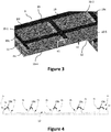
- the figure 4 is an illustrative illustration of a possible longitudinal section of the gripping device 1 of the figure 1 , at the central keys 10-4 to 10-6 and 11-2. It illustrates an embodiment of the various profiles P1 to P4 for the keys.
- the figure 3 also illustrates the different profiles P3 and P4 of keys 10-1, 10-2, 10-4 and 10-5.
- a first profile P1 makes it possible to determine the right side edge of the input device.
- the P2 profile of the correction key introduces himself in the form of a vertical slope.
- the P3 profiles of the numeric keys are generally wave-shaped. They are different from the P2 profile, allowing the visually impaired user to differentiate the number keys from the function keys.
- the left outer profile P4 is also different from the right outer profile P1, in particular by the size of the plates (P14 vs Pl1), thus allowing the user to determine the orientation of the device when it is placed on the touch screen.
- the stud 13 of the five button 10-5 is also visible on this button and allows the five button to be quickly identified.
- the plate 30 is made of an electrically insulating material, so as not to emit a stray capacitance that is difficult to control.
- the plate is made of rigid, transparent plastic.
- the lower face 18 of the plate 30 comprises, in each of its four angles, a foot 16-1 to 16-4 which is generally flat with a thickness between 0.1 and 0.4 mm.
- the feet aim to ensure that it is the contact pads 15-1 and 15-2 which press on the touch screen 24, even if the plate 30 is a little twisted.
- the lower face comprises only two feet, those referenced 16-1 and 16-2 (that is to say those located in the two "top” angles, in the plane of the upper face of the plate. ). This prevents limping of the gripper, whether the plate is concave or convex.
- the lower face 18 of the plate 30 comprises one or more anti-slip feet 16-1 'and 16-2', made of a non-slip material. It is for example a material with multiple pins, which behaves like the filaments of the Gecko (the lizard). With this (s) anti-slip foot (s), once the input device has been placed on the touch screen 24, it does not move during input. This is particularly effective on glass.
- the lower face 18 of the plate 30 comprises, for example in its middle, a suction cup (40) integral with the lower face and intended to come in. contact with the touch screen 24.
- a suction cup (40) integral with the lower face and intended to come in. contact with the touch screen 24.
- the plate 30 is made of translucent non-conductive silicone, the hardness of which is for example between 60 and 90 Shores A.
- the plate can be deformed and adapt perfectly to the flatness of the touch screen ( and therefore a priori not to require a foot).
- the production of the silicone plate allows it to adhere to the touch screen, to be deformable under its weight and with good shape memory.
- the plate 30 is for example approximately the dimensions of a bank card (54 mm ⁇ 85 mm, to within a few millimeters). This makes it possible to place the input device 1 in a wallet or a card holder, in the same place as the bank card.
- the lower angles, left and right, of the upper face 17 of the plate 3 do not include any key.
- the two contact pads 15-1 and 15-2 are positioned in the corresponding (that is to say superimposed) zones of the lower face 18 of the plate 30.
- the two contact pads 15-1 and 15-2 are very flexible and flat, so as to maximize their surface in contact with the touch screen 24. They have for example the shape of a disc with a diameter of between 6 and 8 mm. . They are for example made of conductive silicone, the hardness of which is between 40 and 80 Shores A. Other techniques can be used to make contact pads: metal parts, designs made with conductive inks (directly on the underside of the the plate, or on a film itself then transferred to the underside of the plate), etc.
- the center distance between the contact pads is determined and known to the terminal controller, which can thus, after having detected the two contact pads (see method described below), detect that the input device 1 has been affixed to the panel. tactile 24.
- the controller can also deduce therefrom the modulo 180 ° position and orientation of the input device 1 on the tactile screen 24.
- the input device comprises at least three contact pads 15-1, 15-2 and 15-3.
- the controller can detect the orientation of the input device without modulo 180 °.
- three contact pads there is less confusion possible with a center distance of fingers placed on the touch screen.
- the two contact pads 15-1 and 15-2 have different shapes (for example disc for one and rectangle for the other).
- the controller can also detect the orientation of the input device without modulo 180 °.
- the input device comprises a single contact pad, having a particular shape (for example oblong or rectangular, with a sufficient length).
- the controller can identify the single contact patch and know its orientation (modulo 180 °); and from there also know the orientation (modulo 180 °) of the input device when it is affixed to the touch screen.
- the network of conductive tracks 19 is shown in black. It comprises tracks arranged in lines 191 and in columns 19c, which form a grid over a substantial part of the upper face 17 of the plate 30.
- the network of conductive tracks 19 is electrically connected to the contact pads 15-1 and 15-2 via electrical connections 14-1 (only one connection is visible on the figure 2A ) (for example sections of conductive tracks and via).
- the contact pads 15-1 and 15-2 form the thickness of the plate (in this case, the via are not necessary).
- the network of conductive tracks 19 is formed in the upper part of the grid of profiles.
- each conductive track 19c, 191 is formed in the upper part of one of the profiles P1 to P4.
- the network of conductive tracks 19 must extend over a sufficiently large area, thus making it possible to act with more nodes of the matrix of electrodes (row / column intersection) of the touch screen, and therefore to have a load which varies during capacitive sweeps. This is particularly the case when the network of conductive tracks 19 is formed in the upper part of the grid of profiles and when the plate 30 is substantially the dimensions of a bank card (that is to say approximately 54 mm x 85 mm).
- the network of conductive tracks 19 and the lower face 18 of the plate 30 are separated by a distance (height denoted e1 on the figure 3 ) between 1.5 mm and 4.5 mm.
- the conductive tracks have a width of between 0.5 mm and 2 mm.
- the network of conductive tracks has a low capacitance, which allows it both to interact with the touch screen during capacitive scans (and to move the charges of the network of conductive tracks, which avoids a recalibration of the screen. touch by the controller), but also not to be detected as a significant variation in capacitance (which would cause false detection of a significant press).
- the minimum value of the height e1 (1.5 mm). Indeed, since the input device has a free placement on the touch screen, and that the positions of the nodes of the matrix of electrodes (intersection rows / columns) of the touch screen are not known, we can have an alignment perfect of a conductive track with an electrode (row or column) of the touch screen. If this is the case, and if the distance between this conductive track and this electrode is small, then the capacitance between these two elements (track and electrode) will increase significantly, which is not desirable. With the minimum value of the height e1, we remain with a low capacitance for the network of conductive tracks.
- the maximum value of the height e1 (4 mm) can (in theory) be exceeded, but here it is the ergonomics, to access the bottom of the keys, which is affected.
- the range of values of the height e1 is respected, but the network of conductive tracks 19 is not formed in the upper part of the grid of profiles. It is for example formed, on the plane of the upper face 17 of the plate 30, in a zone adjoining and / or surrounding that where the keys of the entry zone matrix are located. In this case, the total area of the plate 30 can be increased over the particular implementation illustrated.
- the network of conductive tracks has a resistance, between contact pads, between 20 ⁇ and 150 k ⁇ . A relatively low resistance improves the responsiveness of the input device 1.
- the network of conductive tracks 19 is configured so that, when the input device 1 is affixed to the touch screen, and even in the absence of a finger pressing on the network of conductive tracks, the network of conductive tracks interacts with the touch screen during capacitive scanning cycles, which prevents a recalibration of the reference values (which itself would prevent each of the contact pads 15-1 and 15-2 from being detected as a significant press), without the network of conductive tracks 19 itself being detected as a significant press.
- the capacitance is defined in proportion to the facing surface, and inversely in proportion to the distance of the insulator. Consequently, the contact pads 15-1 and 15-2, very close to the electrodes of the touch screen 24, have a measurable capacity (of the order of a stylus), allowing them to each be detected as a support. significant, while the network of conductive tracks 19 (greater height e1, and with thin conductive tracks) has a much lower capacitance, allowing it not to be detected as a significant support.
- the network of conductive tracks 19 has another important characteristic: it extends over a larger area than the contact pads, and therefore, even if its capacity is low, it interacts with several nodes of the electrode matrix ( row / column intersection) of the touch screen.
- the fact that the conductive tracks are connected in a network allows charges to flow freely therein.
- charges come and go in the network of conductive tracks, as well as between the contact pads and the network of conductive tracks. This therefore changes very slightly the load of the network of conductive tracks and of the contact pads. Therefore, for the relevant nodes of the electrode array (i.e.
- the controller measures variations in capacitance (with respect to values reference) which are not fixed over successive cycles, and therefore decides not to recalibrate the touch screen (i.e. to modify the reference values for the nodes concerned). This non-recalibration allows each of the contact pads 15-1 and 15-2 to continue to be detected as a significant press.
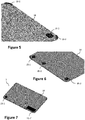
- the figure 10 illustrates a data entry device 100, according to a variant of the first embodiment of the invention, in “portrait” format, particularly suitable for use with touch panels also of “small format” portrait type (for which, the data entry device 1 of the first embodiment, in “landscape” format, would not be usable). Its operation is exactly the same as that of the first embodiment.
- the ten number keys 10-0 'to 10-9' (still on four rows and three columns) are arranged above (and no longer on the left) of the three functional keys 11-1 'to 11-3', themselves arranged on a row (and no longer on a column).
- the lower angles, left and right, of the upper face 17 of the plate 3 do not include any key. It is in the corresponding (that is to say superimposed) zones of the lower face 18 of the plate 30 that the two contact pads 15-1 'and 15-2' are positioned.
- the center distance between contact pads is not the same as in the first embodiment.
- the terminal controller which knows the center distance between contact pads of each of the types of input device 1, 100, can detect which type of input device has been affixed to the touch screen (and thus deduce the position each of the keys of the input device affixed).
- a corner of the input device (e.g. top right, see figure 10 ) is bevelled and allows the user to orient the input device without possible confusion. This prevents the user from placing the input device horizontally.
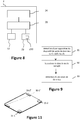
- the figure 8 shows an example of the structure of terminal 2 of the figure 1 , implementing a data entry method according to the invention (for example the particular embodiment described below in relation to the figure 9 ).
- the terminal 2 comprises a touch screen 24 (see description above), a random access memory 22 (for example a RAM memory), a processing unit 61 (notably forming the controller (control unit) of the touch screen 24; see description above), equipped for example with a processor, and controlled by a computer program 230 stored in a read only memory 23 (for example a ROM memory or a hard disk).
- a computer program 230 stored in a read only memory 23 (for example a ROM memory or a hard disk).
- the code instructions of the computer program 230 are for example loaded into the random access memory 22 before being executed by the processor of the processing unit 21.
- FIG 8 illustrates only one particular way, among several possible, of carrying out the algorithm detailed below in relation to the figure 9 .
- the technique of the invention can be carried out equally well on a reprogrammable computing machine (a PC computer, a DSP processor or a microcontroller) executing a program comprising a sequence of instructions, or on a dedicated computing machine (for example a set of logic gates such as an FPGA or ASIC, or any other hardware module).
- a reprogrammable computing machine a PC computer, a DSP processor or a microcontroller
- a program comprising a sequence of instructions
- a dedicated computing machine for example a set of logic gates such as an FPGA or ASIC, or any other hardware module.
- the corresponding program (that is to say the sequence of instructions) can be stored in a removable storage medium (such as for example a floppy disk, CD-ROM or DVD-ROM) or not, this storage medium being partially or totally readable by a computer or a processor.
- a removable storage medium such as for example a floppy disk, CD-ROM or DVD-ROM
- the figure 9 presents a flowchart of a method according to a particular embodiment of the invention, executed by the terminal 2.
- a step 91 the terminal detects an affixing of the data entry device 1 on the touch screen 24. This first detection is based on a detection of the contact pad or pads 15-1 and 15-2.
- the controller of the touch screen detects the two (or three) contact pads, and possibly one or more significant presses if the user holds the input device in hand and one of his fingers touches the touch screen. As explained above, this detection is possible because the contact pads are electrically conductive and in direct contact. with the touch screen. The level of detection of the contact pads is acceptable because it is lower than if one pressed with a finger, but of a level comparable to that of a stylus. It is recalled that the network of conductive tracks is not detected but makes it possible to avoid a recalibration of the touch screen (which would prevent the detection of the contact pads).
- the distance (s) between contact pads being known to the controller (with some variations), the latter is able to recognize that it is a input device 1 which has been installed.
- the controller also checks that each of the input zones (keys) 10-0 to 10-9 and 11-1 to 11-3 is present at least partially in an active zone of the touch screen 24. We consider for example if 80% of a key is in the active area, then this is still acceptable.
- step 92 if the determinations and verifications of step 91 have been carried out successfully, the terminal switches to an input mode suitable for the data input device (hereinafter called “blind mode”). To acknowledge the correct presence of the input device and confirm to the user the switching to blind mode, an audible notification is emitted by the terminal. In addition, in order to secure the next data entry phase, the terminal erases the virtual keyboard on the touch screen. In addition, in blind mode, the setting of the touch screen is for example such that it makes it possible to detect lower levels when entering the PIN code. This makes it possible to compensate, if necessary, for the fact that the user's finger is in contact with the touch screen 24 via the input device 1.
- a step 93 the terminal detects an entry of data by the user. This second detection is based on the detection of one or more presses of a user's finger on the keys of the input device.
- the controller detects four successive presses of the number keys 10-0 to 10-9, followed by a press of the validation key 11-3. On exiting the PIN code entry, you switch back to standard settings ("normal mode").
- Another way to filter support is to have force detection. In this case, it is not necessary to have a filtering on the duration of the pressure. In addition or not to the force detection, a haptic effect can be added to the keyboard.
- Exiting blind mode can be done in several ways. If a contact pad is no longer detected by the controller or if the controller detects that the keys are no longer in the active zone of the touch screen, the user is notified, for example by a "negative" sound feedback ( long grave) that we exit the blind mode, and that we return to a display according to the classic mode.
- the input device can move and we are always able to detect it (with its orientation) and therefore to define the key (s) supported.
Landscapes
- Engineering & Computer Science (AREA)
- Theoretical Computer Science (AREA)
- General Engineering & Computer Science (AREA)
- Physics & Mathematics (AREA)
- General Physics & Mathematics (AREA)
- Human Computer Interaction (AREA)
- Computer Security & Cryptography (AREA)
- Computer Hardware Design (AREA)
- Software Systems (AREA)
- Position Input By Displaying (AREA)
Claims (15)
- Dateneingabesystem, umfassend einen Touchscreen (24) eines Endgeräts (2) und eine Dateneingabevorrichtung (1), die dazu bestimmt ist, auf dem Touchscreen aufgelegt zu werden, wobei der Touchscreen kapazitiv ist und Zeilen- und Spaltenelektroden aufweist, die eine Elektrodenmatrix bilden, die Knoten aufweist, und von einer Steuereinheit (21) gesteuert wird, die konfiguriert ist, um Zyklen des kapazitiven Abtastens und des Messens der Kapazitätsänderungen der Knoten in Bezug auf Referenzwerte durchzuführen, signifikante Auflagen auf dem Touchscreen in Abhängigkeit von den gemessenen Kapazitätsänderungen zu erfassen und die Referenzwerte in Abhängigkeit von den gemessenen Kapazitätsänderungen neu zu kalibrieren, dadurch gekennzeichnet, dass es aufweist:• eine im Allgemeinen quaderförmige Platte (30), umfassend eine im Allgemeinen flache Unterseite (18) zum Auflegen der Vorrichtung auf den Touchscreen, und eine Oberseite (17), umfassend eine Matrix mit Eingabefeldern (10-0 bis 10-9 und 11-1 bis 11-3), die eine Tastatur bildet, wobei die Eingabefelder eine Dicke (e2) aufweisen, die konfiguriert ist, um ein Erfassen eines Fingers durch den Touchscreen zu ermöglichen, wenn die Vorrichtung auf dem Touchscreen aufgelegt ist,• mindestens ein flaches Kontaktpad (15-1 bis 15-3), das elektrisch leitend und mit der Unterseite fest verbunden ist, wobei das mindestens eine Kontaktpad eine Kapazität aufweist, die es ihm ermöglicht, als signifikante Auflage erfasst zu werden, und• ein Leiterbahnennetz (19), das sich über mindestens einen Teil der Oberseite erstreckt und elektrisch mit dem mindestens einen Kontaktpad verbunden ist, wobei das Leiterbahnennetz eine Kapazität aufweist, die es ihm ermöglicht, nicht als signifikante Auflage erfasst zu werden, und eine Fläche einnimmt, die einerseits größer als die Fläche ist, die von dem mindestens einen Kontaktpad eingenommen wird, und andererseits ausreichend ist, damit das Leiterbahnennetz bei den Zyklen des kapazitiven Abtastens mit mehreren Knoten der Elektrodenmatrix in Form von Ladungen interagiert, die sich in dem Leiterbahnennetz und zwischen dem mindestens einen Kontaktpad und dem Leiterbahnennetz hin und her bewegen, wodurch die Ladung des Leiterbahnennetzes und dem mindestens einen Kontaktpad geändert wird und folglich die Steuereinheit für die Knoten der Elektrodenmatrix, die dem Leiterbahnennetz und dem mindestens einen Kontaktpad gegenüber liegen, die betreffende Knoten genannt werden, Kapazitätsänderungen in aufeinanderfolgenden Zyklen, die nicht festgelegt sind, misst und somit entscheidet, keine Neukalibrierung der Referenzwerte für die betreffenden Knoten vorzunehmen.
- System nach Anspruch 1, dadurch gekennzeichnet, dass die Unterseite mindestens zwei Kontaktpads (15-1 bis 15-3) aufweist.
- System nach Anspruch 2, dadurch gekennzeichnet, dass die mindestens zwei Kontaktpads (15-1 bis 15-2') verschiedene Formen aufweisen.
- System nach Anspruch 1, dadurch gekennzeichnet, dass die Unterseite mindestens drei Kontaktpads (15-1 bis 15-3) aufweist.
- System nach einem der Ansprüche 1 bis 4, dadurch gekennzeichnet, dass die Matrix mit Eingabefeldern, die eine Tastatur bildet, einen Satz von Eingabetasten aufweist, die im Allgemeinen flach sind, die auf der Oberseite gebildet sind und voneinander durch ein Profilraster (P1 bis P4) mit vorbestimmten Höhen und/oder Formen getrennt sind, und dadurch, dass das Leiterbahnennetz (19) im oberen Teil aus dem Profilraster gebildet ist.
- System nach einem der Ansprüche 1 bis 5, dadurch gekennzeichnet, dass das Leiterbahnennetz (19) und die Unterseite (18) durch einen Abstand (e1) getrennt sind, der zwischen 1,5 mm und 4,5 mm beträgt, und dadurch, dass die Leiterbahnen eine Breite aufweisen, die zwischen 0,5 mm und 2 mm beträgt.
- System nach Anspruch 1 bis 6, dadurch gekennzeichnet, dass die Unterseite mindestens zwei Kontaktpads aufweist und dadurch, dass das Leiterbahnennetz einen Widerstand zwischen Kontaktpads aufweist, der zwischen 20 Ω und 150 kΩ beträgt.
- System nach einem der Ansprüche 1 bis 7, dadurch gekennzeichnet, dass das Leiterbahnennetz (19) auf der Oberseite gedruckt ist und von einer nichtleitenden, abriebfesten Schicht bedeckt ist.
- System nach einem der Ansprüche 1 bis 7, dadurch gekennzeichnet, dass das Leiterbahnennetz aus einem dicken leitfähigen Material hergestellt ist, das eine Dicke von mindestens 0,3 mm aufweist.
- System nach einem der Ansprüche 1 bis 9, dadurch gekennzeichnet, dass die Platte (30) aus einem elektrisch isolierenden Material gebildet ist.
- System nach einem der Ansprüche 1 bis 10, dadurch gekennzeichnet, dass die Platte (30) aus einem starren und transparenten Kunststoffmaterial gebildet ist.
- System nach Anspruch 11, dadurch gekennzeichnet, dass die Unterseite (18) vier Ecken besitzt und in mindestens zwei benachbarten Ecken unter den Ecken einen im Allgemeinen flachen Fuß (16-1 bis 16-4) von einer Dicke zwischen 0,1 und 0,4 mm aufweist.
- System nach einem der Ansprüche 1 bis 10, dadurch gekennzeichnet, dass die Platte (30) aus transluzentem Silikon gebildet ist, das sich verformen und perfekt an die Flachheit des Touchscreens anpassen kann.
- System nach einem der Ansprüche 1 bis 13, dadurch gekennzeichnet, dass es mindestens einen Saugnapf (40) und/oder mindestens einen Antirutsch-Fuß (16-1' und 16-2') aufweist, der (die) aus einem rutschfesten Material erstellt ist (sind), der (die) mit der Unterseite fest verbunden ist (sind) und dazu bestimmt ist (sind), mit dem Touchscreen in Kontakt zu kommen.
- System nach einem der Ansprüche 1 bis 14, dadurch gekennzeichnet, dass die Matrix mit Eingabefeldern (10-0 bis 10-9 und 11-1 bis 11-3), die eine Tastatur bildet, für eine Eingabetastatur eines Geheimcodes auf einem Zahlungsendgerät repräsentativ ist.
Applications Claiming Priority (1)
| Application Number | Priority Date | Filing Date | Title |
|---|---|---|---|
| FR1855293A FR3082641B1 (fr) | 2018-06-15 | 2018-06-15 | Dispositif de saisie de donnees destine a etre appose sur une dalle tactile d’un terminal, procede et systeme de saisie correspondants. |
Publications (2)
| Publication Number | Publication Date |
|---|---|
| EP3582090A1 EP3582090A1 (de) | 2019-12-18 |
| EP3582090B1 true EP3582090B1 (de) | 2020-12-02 |
Family
ID=62952160
Family Applications (1)
| Application Number | Title | Priority Date | Filing Date |
|---|---|---|---|
| EP19179642.4A Active EP3582090B1 (de) | 2018-06-15 | 2019-06-12 | Datenerfassungsvorrichtung zur auflage auf eine berührungsempfindliche platte eines endgeräts, entsprechendes datenerfassungverfahren und -system |
Country Status (5)
| Country | Link |
|---|---|
| US (1) | US10884565B2 (de) |
| EP (1) | EP3582090B1 (de) |
| CA (1) | CA3046511A1 (de) |
| ES (1) | ES2845250T3 (de) |
| FR (1) | FR3082641B1 (de) |
Families Citing this family (7)
| Publication number | Priority date | Publication date | Assignee | Title |
|---|---|---|---|---|
| US20210255730A1 (en) * | 2020-02-18 | 2021-08-19 | Sigmasense, Llc. | Input/Output (I/O) Operative Touch Sensor Device (TSD) |
| US11907484B2 (en) | 2015-06-22 | 2024-02-20 | Sigmasense, Llc. | Function and orientation identification for input/output (I/O) operative touch sensor device (TSD) |
| US10983601B1 (en) * | 2020-01-17 | 2021-04-20 | Assa Abloy Ab | Visually impaired mode keypad |
| GB2592201B (en) * | 2020-02-18 | 2023-03-29 | Miura Systems Ltd | Touchscreen Interface |
| US11079888B1 (en) | 2020-02-18 | 2021-08-03 | Sigmasense, Llc. | Sensitivity region of interest processing (ROIP) for input/output (I/O) operative touch sensor device (TSD) |
| US11341496B2 (en) | 2020-06-03 | 2022-05-24 | Fiserv, Inc. | Hardware device for entering a PIN via tapping on a touch screen display |
| FR3115899B1 (fr) * | 2020-10-30 | 2023-11-17 | Banks And Acquirers Int Holding | Dispositif de saisie de données destiné à être apposé sur une dalle tactile d’un terminal et procédé de saisie correspondant |
Family Cites Families (12)
| Publication number | Priority date | Publication date | Assignee | Title |
|---|---|---|---|---|
| US20060256090A1 (en) * | 2005-05-12 | 2006-11-16 | Apple Computer, Inc. | Mechanical overlay |
| EP2270639B1 (de) * | 2009-06-30 | 2016-10-12 | BlackBerry Limited | Auflage für elektronisches Gerät und Verfahren zu dessen Identifizierung |
| US8411066B2 (en) | 2010-01-05 | 2013-04-02 | 3M Innovative Properties Company | High speed noise tolerant multi-touch touch device and controller therefor |
| US10042480B2 (en) * | 2010-04-08 | 2018-08-07 | Google Technology Holdings LLC | Apparatuses, methods, and systems for an electronic device with a detachable user input attachment |
| US10013092B2 (en) * | 2013-09-27 | 2018-07-03 | Sensel, Inc. | Tactile touch sensor system and method |
| DE202014000752U1 (de) * | 2014-01-30 | 2014-02-28 | Lucian Depold | Bedienungshilfe für ein berührungsempfindliches Display |
| WO2015120408A1 (en) * | 2014-02-07 | 2015-08-13 | Snowshoefood, Inc. | Hardware tools and methods for capacitive sensor enabled authentication |
| WO2016131963A1 (en) * | 2015-02-19 | 2016-08-25 | T+Ink Gmbh | Self-grounding capacitive information carrier and its use |
| US9965116B1 (en) * | 2015-07-14 | 2018-05-08 | Square, Inc. | Tactile overlay for touchscreen device |
| FR3055990B1 (fr) * | 2016-09-12 | 2022-08-12 | Joue | Interface tactile tangible reconfigurable |
| JP6935347B2 (ja) * | 2018-02-27 | 2021-09-15 | 株式会社東海理化電機製作所 | タッチセンサ装置及び静電容量較正プログラム |
| US10921912B2 (en) * | 2018-09-27 | 2021-02-16 | Intel Corporation | Technologies for interfacing an input overlay device with a touch screen compute device |
-
2018
- 2018-06-15 FR FR1855293A patent/FR3082641B1/fr not_active Expired - Fee Related
-
2019
- 2019-06-12 EP EP19179642.4A patent/EP3582090B1/de active Active
- 2019-06-12 US US16/439,152 patent/US10884565B2/en active Active
- 2019-06-12 ES ES19179642T patent/ES2845250T3/es active Active
- 2019-06-13 CA CA3046511A patent/CA3046511A1/en active Pending
Also Published As
| Publication number | Publication date |
|---|---|
| CA3046511A1 (en) | 2019-12-15 |
| US10884565B2 (en) | 2021-01-05 |
| ES2845250T3 (es) | 2021-07-26 |
| FR3082641B1 (fr) | 2021-11-05 |
| EP3582090A1 (de) | 2019-12-18 |
| US20200026392A1 (en) | 2020-01-23 |
| FR3082641A1 (fr) | 2019-12-20 |
Similar Documents
| Publication | Publication Date | Title |
|---|---|---|
| EP3582090B1 (de) | Datenerfassungsvorrichtung zur auflage auf eine berührungsempfindliche platte eines endgeräts, entsprechendes datenerfassungverfahren und -system | |
| US10359882B2 (en) | Electronic device including touch-fingerprint complex sensor | |
| EP2321833A1 (de) | Mehrkontakt-berührungssensor mit zwischenelementen von variabler grösse und impedanz | |
| US10127427B2 (en) | On-screen fingerprint sensor and electronic device including the same | |
| CN105549775B (zh) | 层压体 | |
| US20170083739A1 (en) | Electronic apparatus with multi-finger fingerprint identifying function | |
| EP3451138B1 (de) | Erfassungsvorrichtung auf einer berührungsempfindlichen oberfläche und entsprechendes verfahren | |
| EP2030143B1 (de) | Einrichtung zur abschirmung vor störungen aus elektrischen geräten | |
| CN106249953A (zh) | 一种压感触摸屏及显示装置 | |
| FR3053137A1 (fr) | Procede d'interaction homme-machine par combinaison de commandes tactiles et sans contact. | |
| EP3101591A1 (de) | Endgerät zur erkennung eines fingerabdrucks | |
| FR3033203A1 (fr) | Procede pour interagir avec un appareil electronique et/ou informatique mettant en œuvre une surface de commande capacitive et une surface peripherique, interface et appareil mettant en œuvre ce procede | |
| US20160216813A1 (en) | Electronic device including finger biometric sensor including transparent conductive blocking areas carried by a touch display and related methods | |
| EP2569765A1 (de) | Tragbare vorrichtung mit einem berührungsbildschirm und entsprechendes anwendungsverfahren dafür | |
| FR3005763A1 (fr) | Dispositif et procede d'interface de commande capacitive adapte a la mise en œuvre d'electrodes de mesures fortement resistives | |
| EP3451139B1 (de) | Eingabevorrichtung für ein touchscreen und entsprechendes verfahren | |
| WO2016034380A1 (fr) | Dispositif d'interface de commande et capteur d'empreintes digitales | |
| EP4237932A1 (de) | Dateneingabevorrichtung zur anbringung an einem berührungsbildschirm eines endgeräts und entsprechendes eingabeverfahren | |
| CN104050485A (zh) | 指纹识别传感器、指纹识别检测组件及终端设备 | |
| CN110892402A (zh) | 指纹识别装置、终端设备和指纹识别装置的制造方法 | |
| FR3130052A3 (fr) | Dispositif d’aide à la saisie de données pour écran tactile | |
| FR3112628A1 (fr) | Dispositif de pointage informatique | |
| FR3017471A1 (fr) | Procede d'interaction avec un appareil electronique/informatique tactile et appareil mettant en œuvre un tel procede |
Legal Events
| Date | Code | Title | Description |
|---|---|---|---|
| PUAI | Public reference made under article 153(3) epc to a published international application that has entered the european phase |
Free format text: ORIGINAL CODE: 0009012 |
|
| STAA | Information on the status of an ep patent application or granted ep patent |
Free format text: STATUS: THE APPLICATION HAS BEEN PUBLISHED |
|
| AK | Designated contracting states |
Kind code of ref document: A1 Designated state(s): AL AT BE BG CH CY CZ DE DK EE ES FI FR GB GR HR HU IE IS IT LI LT LU LV MC MK MT NL NO PL PT RO RS SE SI SK SM TR |
|
| AX | Request for extension of the european patent |
Extension state: BA ME |
|
| STAA | Information on the status of an ep patent application or granted ep patent |
Free format text: STATUS: REQUEST FOR EXAMINATION WAS MADE |
|
| 17P | Request for examination filed |
Effective date: 20200305 |
|
| RBV | Designated contracting states (corrected) |
Designated state(s): AL AT BE BG CH CY CZ DE DK EE ES FI FR GB GR HR HU IE IS IT LI LT LU LV MC MK MT NL NO PL PT RO RS SE SI SK SM TR |
|
| GRAP | Despatch of communication of intention to grant a patent |
Free format text: ORIGINAL CODE: EPIDOSNIGR1 |
|
| STAA | Information on the status of an ep patent application or granted ep patent |
Free format text: STATUS: GRANT OF PATENT IS INTENDED |
|
| RIC1 | Information provided on ipc code assigned before grant |
Ipc: G06F 3/041 20060101AFI20200717BHEP Ipc: G06F 21/83 20130101ALN20200717BHEP Ipc: G06F 3/0488 20130101ALI20200717BHEP Ipc: G06F 21/31 20130101ALI20200717BHEP Ipc: G06F 3/044 20060101ALI20200717BHEP Ipc: G06F 3/039 20130101ALI20200717BHEP |
|
| INTG | Intention to grant announced |
Effective date: 20200814 |
|
| GRAS | Grant fee paid |
Free format text: ORIGINAL CODE: EPIDOSNIGR3 |
|
| GRAA | (expected) grant |
Free format text: ORIGINAL CODE: 0009210 |
|
| STAA | Information on the status of an ep patent application or granted ep patent |
Free format text: STATUS: THE PATENT HAS BEEN GRANTED |
|
| AK | Designated contracting states |
Kind code of ref document: B1 Designated state(s): AL AT BE BG CH CY CZ DE DK EE ES FI FR GB GR HR HU IE IS IT LI LT LU LV MC MK MT NL NO PL PT RO RS SE SI SK SM TR |
|
| REG | Reference to a national code |
Ref country code: GB Ref legal event code: FG4D Free format text: NOT ENGLISH |
|
| REG | Reference to a national code |
Ref country code: CH Ref legal event code: EP Ref country code: AT Ref legal event code: REF Ref document number: 1341655 Country of ref document: AT Kind code of ref document: T Effective date: 20201215 |
|
| REG | Reference to a national code |
Ref country code: IE Ref legal event code: FG4D Free format text: LANGUAGE OF EP DOCUMENT: FRENCH |
|
| REG | Reference to a national code |
Ref country code: DE Ref legal event code: R096 Ref document number: 602019001561 Country of ref document: DE |
|
| PG25 | Lapsed in a contracting state [announced via postgrant information from national office to epo] |
Ref country code: RS Free format text: LAPSE BECAUSE OF FAILURE TO SUBMIT A TRANSLATION OF THE DESCRIPTION OR TO PAY THE FEE WITHIN THE PRESCRIBED TIME-LIMIT Effective date: 20201202 Ref country code: FI Free format text: LAPSE BECAUSE OF FAILURE TO SUBMIT A TRANSLATION OF THE DESCRIPTION OR TO PAY THE FEE WITHIN THE PRESCRIBED TIME-LIMIT Effective date: 20201202 Ref country code: NO Free format text: LAPSE BECAUSE OF FAILURE TO SUBMIT A TRANSLATION OF THE DESCRIPTION OR TO PAY THE FEE WITHIN THE PRESCRIBED TIME-LIMIT Effective date: 20210302 Ref country code: GR Free format text: LAPSE BECAUSE OF FAILURE TO SUBMIT A TRANSLATION OF THE DESCRIPTION OR TO PAY THE FEE WITHIN THE PRESCRIBED TIME-LIMIT Effective date: 20210303 |
|
| REG | Reference to a national code |
Ref country code: NL Ref legal event code: MP Effective date: 20201202 |
|
| REG | Reference to a national code |
Ref country code: AT Ref legal event code: MK05 Ref document number: 1341655 Country of ref document: AT Kind code of ref document: T Effective date: 20201202 |
|
| PG25 | Lapsed in a contracting state [announced via postgrant information from national office to epo] |
Ref country code: LV Free format text: LAPSE BECAUSE OF FAILURE TO SUBMIT A TRANSLATION OF THE DESCRIPTION OR TO PAY THE FEE WITHIN THE PRESCRIBED TIME-LIMIT Effective date: 20201202 Ref country code: PL Free format text: LAPSE BECAUSE OF FAILURE TO SUBMIT A TRANSLATION OF THE DESCRIPTION OR TO PAY THE FEE WITHIN THE PRESCRIBED TIME-LIMIT Effective date: 20201202 Ref country code: SE Free format text: LAPSE BECAUSE OF FAILURE TO SUBMIT A TRANSLATION OF THE DESCRIPTION OR TO PAY THE FEE WITHIN THE PRESCRIBED TIME-LIMIT Effective date: 20201202 Ref country code: BG Free format text: LAPSE BECAUSE OF FAILURE TO SUBMIT A TRANSLATION OF THE DESCRIPTION OR TO PAY THE FEE WITHIN THE PRESCRIBED TIME-LIMIT Effective date: 20210302 |
|
| PG25 | Lapsed in a contracting state [announced via postgrant information from national office to epo] |
Ref country code: HR Free format text: LAPSE BECAUSE OF FAILURE TO SUBMIT A TRANSLATION OF THE DESCRIPTION OR TO PAY THE FEE WITHIN THE PRESCRIBED TIME-LIMIT Effective date: 20201202 Ref country code: NL Free format text: LAPSE BECAUSE OF FAILURE TO SUBMIT A TRANSLATION OF THE DESCRIPTION OR TO PAY THE FEE WITHIN THE PRESCRIBED TIME-LIMIT Effective date: 20201202 |
|
| REG | Reference to a national code |
Ref country code: LT Ref legal event code: MG9D |
|
| REG | Reference to a national code |
Ref country code: ES Ref legal event code: FG2A Ref document number: 2845250 Country of ref document: ES Kind code of ref document: T3 Effective date: 20210726 |
|
| PG25 | Lapsed in a contracting state [announced via postgrant information from national office to epo] |
Ref country code: CZ Free format text: LAPSE BECAUSE OF FAILURE TO SUBMIT A TRANSLATION OF THE DESCRIPTION OR TO PAY THE FEE WITHIN THE PRESCRIBED TIME-LIMIT Effective date: 20201202 Ref country code: SK Free format text: LAPSE BECAUSE OF FAILURE TO SUBMIT A TRANSLATION OF THE DESCRIPTION OR TO PAY THE FEE WITHIN THE PRESCRIBED TIME-LIMIT Effective date: 20201202 Ref country code: SM Free format text: LAPSE BECAUSE OF FAILURE TO SUBMIT A TRANSLATION OF THE DESCRIPTION OR TO PAY THE FEE WITHIN THE PRESCRIBED TIME-LIMIT Effective date: 20201202 Ref country code: EE Free format text: LAPSE BECAUSE OF FAILURE TO SUBMIT A TRANSLATION OF THE DESCRIPTION OR TO PAY THE FEE WITHIN THE PRESCRIBED TIME-LIMIT Effective date: 20201202 Ref country code: PT Free format text: LAPSE BECAUSE OF FAILURE TO SUBMIT A TRANSLATION OF THE DESCRIPTION OR TO PAY THE FEE WITHIN THE PRESCRIBED TIME-LIMIT Effective date: 20210405 Ref country code: RO Free format text: LAPSE BECAUSE OF FAILURE TO SUBMIT A TRANSLATION OF THE DESCRIPTION OR TO PAY THE FEE WITHIN THE PRESCRIBED TIME-LIMIT Effective date: 20201202 Ref country code: LT Free format text: LAPSE BECAUSE OF FAILURE TO SUBMIT A TRANSLATION OF THE DESCRIPTION OR TO PAY THE FEE WITHIN THE PRESCRIBED TIME-LIMIT Effective date: 20201202 |
|
| PG25 | Lapsed in a contracting state [announced via postgrant information from national office to epo] |
Ref country code: AT Free format text: LAPSE BECAUSE OF FAILURE TO SUBMIT A TRANSLATION OF THE DESCRIPTION OR TO PAY THE FEE WITHIN THE PRESCRIBED TIME-LIMIT Effective date: 20201202 |
|
| REG | Reference to a national code |
Ref country code: DE Ref legal event code: R097 Ref document number: 602019001561 Country of ref document: DE |
|
| PG25 | Lapsed in a contracting state [announced via postgrant information from national office to epo] |
Ref country code: IS Free format text: LAPSE BECAUSE OF FAILURE TO SUBMIT A TRANSLATION OF THE DESCRIPTION OR TO PAY THE FEE WITHIN THE PRESCRIBED TIME-LIMIT Effective date: 20210402 |
|
| PLBE | No opposition filed within time limit |
Free format text: ORIGINAL CODE: 0009261 |
|
| STAA | Information on the status of an ep patent application or granted ep patent |
Free format text: STATUS: NO OPPOSITION FILED WITHIN TIME LIMIT |
|
| PG25 | Lapsed in a contracting state [announced via postgrant information from national office to epo] |
Ref country code: AL Free format text: LAPSE BECAUSE OF FAILURE TO SUBMIT A TRANSLATION OF THE DESCRIPTION OR TO PAY THE FEE WITHIN THE PRESCRIBED TIME-LIMIT Effective date: 20201202 Ref country code: IT Free format text: LAPSE BECAUSE OF FAILURE TO SUBMIT A TRANSLATION OF THE DESCRIPTION OR TO PAY THE FEE WITHIN THE PRESCRIBED TIME-LIMIT Effective date: 20201202 |
|
| 26N | No opposition filed |
Effective date: 20210903 |
|
| PG25 | Lapsed in a contracting state [announced via postgrant information from national office to epo] |
Ref country code: DK Free format text: LAPSE BECAUSE OF FAILURE TO SUBMIT A TRANSLATION OF THE DESCRIPTION OR TO PAY THE FEE WITHIN THE PRESCRIBED TIME-LIMIT Effective date: 20201202 Ref country code: SI Free format text: LAPSE BECAUSE OF FAILURE TO SUBMIT A TRANSLATION OF THE DESCRIPTION OR TO PAY THE FEE WITHIN THE PRESCRIBED TIME-LIMIT Effective date: 20201202 |
|
| PG25 | Lapsed in a contracting state [announced via postgrant information from national office to epo] |
Ref country code: MC Free format text: LAPSE BECAUSE OF FAILURE TO SUBMIT A TRANSLATION OF THE DESCRIPTION OR TO PAY THE FEE WITHIN THE PRESCRIBED TIME-LIMIT Effective date: 20201202 |
|
| REG | Reference to a national code |
Ref country code: GB Ref legal event code: 732E Free format text: REGISTERED BETWEEN 20220127 AND 20220202 |
|
| REG | Reference to a national code |
Ref country code: BE Ref legal event code: MM Effective date: 20210630 |
|
| PG25 | Lapsed in a contracting state [announced via postgrant information from national office to epo] |
Ref country code: LU Free format text: LAPSE BECAUSE OF NON-PAYMENT OF DUE FEES Effective date: 20210612 |
|
| PG25 | Lapsed in a contracting state [announced via postgrant information from national office to epo] |
Ref country code: IE Free format text: LAPSE BECAUSE OF NON-PAYMENT OF DUE FEES Effective date: 20210612 |
|
| PG25 | Lapsed in a contracting state [announced via postgrant information from national office to epo] |
Ref country code: IS Free format text: LAPSE BECAUSE OF FAILURE TO SUBMIT A TRANSLATION OF THE DESCRIPTION OR TO PAY THE FEE WITHIN THE PRESCRIBED TIME-LIMIT Effective date: 20210402 |
|
| REG | Reference to a national code |
Ref country code: DE Ref legal event code: R081 Ref document number: 602019001561 Country of ref document: DE Owner name: BANKS AND ACQUIRES INTERNATIONAL HOLDING, FR Free format text: FORMER OWNER: INGENICO GROUP, PARIS, FR Ref country code: DE Ref legal event code: R082 Ref document number: 602019001561 Country of ref document: DE Representative=s name: STUMPF PATENTANWAELTE PARTGMBB, DE Ref country code: DE Ref legal event code: R081 Ref document number: 602019001561 Country of ref document: DE Owner name: BANKS AND ACQUIRERS INTERNATIONAL HOLDING, FR Free format text: FORMER OWNER: INGENICO GROUP, PARIS, FR |
|
| PG25 | Lapsed in a contracting state [announced via postgrant information from national office to epo] |
Ref country code: BE Free format text: LAPSE BECAUSE OF NON-PAYMENT OF DUE FEES Effective date: 20210630 |
|
| REG | Reference to a national code |
Ref country code: CH Ref legal event code: PL |
|
| PG25 | Lapsed in a contracting state [announced via postgrant information from national office to epo] |
Ref country code: LI Free format text: LAPSE BECAUSE OF NON-PAYMENT OF DUE FEES Effective date: 20220630 Ref country code: CH Free format text: LAPSE BECAUSE OF NON-PAYMENT OF DUE FEES Effective date: 20220630 |
|
| PG25 | Lapsed in a contracting state [announced via postgrant information from national office to epo] |
Ref country code: CY Free format text: LAPSE BECAUSE OF FAILURE TO SUBMIT A TRANSLATION OF THE DESCRIPTION OR TO PAY THE FEE WITHIN THE PRESCRIBED TIME-LIMIT Effective date: 20201202 |
|
| PG25 | Lapsed in a contracting state [announced via postgrant information from national office to epo] |
Ref country code: HU Free format text: LAPSE BECAUSE OF FAILURE TO SUBMIT A TRANSLATION OF THE DESCRIPTION OR TO PAY THE FEE WITHIN THE PRESCRIBED TIME-LIMIT; INVALID AB INITIO Effective date: 20190612 |
|
| PG25 | Lapsed in a contracting state [announced via postgrant information from national office to epo] |
Ref country code: MK Free format text: LAPSE BECAUSE OF FAILURE TO SUBMIT A TRANSLATION OF THE DESCRIPTION OR TO PAY THE FEE WITHIN THE PRESCRIBED TIME-LIMIT Effective date: 20201202 |
|
| PG25 | Lapsed in a contracting state [announced via postgrant information from national office to epo] |
Ref country code: TR Free format text: LAPSE BECAUSE OF FAILURE TO SUBMIT A TRANSLATION OF THE DESCRIPTION OR TO PAY THE FEE WITHIN THE PRESCRIBED TIME-LIMIT Effective date: 20201202 |
|
| PG25 | Lapsed in a contracting state [announced via postgrant information from national office to epo] |
Ref country code: MT Free format text: LAPSE BECAUSE OF FAILURE TO SUBMIT A TRANSLATION OF THE DESCRIPTION OR TO PAY THE FEE WITHIN THE PRESCRIBED TIME-LIMIT Effective date: 20201202 |
|
| REG | Reference to a national code |
Ref country code: DE Ref legal event code: R081 Ref document number: 602019001561 Country of ref document: DE Owner name: BANKS AND ACQUIRERS INTERNATIONAL HOLDING, FR Free format text: FORMER OWNER: BANKS AND ACQUIRES INTERNATIONAL HOLDING, SURESNES, FR |
|
| PGFP | Annual fee paid to national office [announced via postgrant information from national office to epo] |
Ref country code: DE Payment date: 20250618 Year of fee payment: 7 |
|
| PGFP | Annual fee paid to national office [announced via postgrant information from national office to epo] |
Ref country code: GB Payment date: 20250618 Year of fee payment: 7 |
|
| PGFP | Annual fee paid to national office [announced via postgrant information from national office to epo] |
Ref country code: FR Payment date: 20250627 Year of fee payment: 7 |
|
| REG | Reference to a national code |
Ref country code: ES Ref legal event code: PC2A Owner name: BANKS AND ACQUIRERS INTERNATIONAL HOLDING Effective date: 20250930 |
|
| PGFP | Annual fee paid to national office [announced via postgrant information from national office to epo] |
Ref country code: ES Payment date: 20250728 Year of fee payment: 7 |
|
| P01 | Opt-out of the competence of the unified patent court (upc) registered |
Free format text: CASE NUMBER: UPC_APP_0000329_3582090/2026 Effective date: 20260106 |