EP3582238B1 - Structure magnétique cylindrique de type halbach dipolaire - Google Patents
Structure magnétique cylindrique de type halbach dipolaire Download PDFInfo
- Publication number
- EP3582238B1 EP3582238B1 EP19179145.8A EP19179145A EP3582238B1 EP 3582238 B1 EP3582238 B1 EP 3582238B1 EP 19179145 A EP19179145 A EP 19179145A EP 3582238 B1 EP3582238 B1 EP 3582238B1
- Authority
- EP
- European Patent Office
- Prior art keywords
- cylinders
- cylinder
- ria
- magnetic structure
- field
- Prior art date
- Legal status (The legal status is an assumption and is not a legal conclusion. Google has not performed a legal analysis and makes no representation as to the accuracy of the status listed.)
- Active
Links
Images




Classifications
-
- A—HUMAN NECESSITIES
- A61—MEDICAL OR VETERINARY SCIENCE; HYGIENE
- A61N—ELECTROTHERAPY; MAGNETOTHERAPY; RADIATION THERAPY; ULTRASOUND THERAPY
- A61N2/00—Magnetotherapy
- A61N2/06—Magnetotherapy using magnetic fields produced by permanent magnets
-
- G—PHYSICS
- G01—MEASURING; TESTING
- G01R—MEASURING ELECTRIC VARIABLES; MEASURING MAGNETIC VARIABLES
- G01R33/00—Arrangements or instruments for measuring magnetic variables
- G01R33/20—Arrangements or instruments for measuring magnetic variables involving magnetic resonance
- G01R33/28—Details of apparatus provided for in groups G01R33/44 - G01R33/64
- G01R33/38—Systems for generation, homogenisation or stabilisation of the main or gradient magnetic field
- G01R33/383—Systems for generation, homogenisation or stabilisation of the main or gradient magnetic field using permanent magnets
-
- H—ELECTRICITY
- H01—ELECTRIC ELEMENTS
- H01F—MAGNETS; INDUCTANCES; TRANSFORMERS; SELECTION OF MATERIALS FOR THEIR MAGNETIC PROPERTIES
- H01F7/00—Magnets
- H01F7/02—Permanent magnets [PM]
- H01F7/0273—Magnetic circuits with PM for magnetic field generation
- H01F7/0278—Magnetic circuits with PM for magnetic field generation for generating uniform fields, focusing, deflecting electrically charged particles
-
- G—PHYSICS
- G11—INFORMATION STORAGE
- G11C—STATIC STORES
- G11C11/00—Digital stores characterised by the use of particular electric or magnetic storage elements; Storage elements therefor
- G11C11/02—Digital stores characterised by the use of particular electric or magnetic storage elements; Storage elements therefor using magnetic elements
- G11C11/14—Digital stores characterised by the use of particular electric or magnetic storage elements; Storage elements therefor using magnetic elements using thin-film elements
- G11C11/155—Digital stores characterised by the use of particular electric or magnetic storage elements; Storage elements therefor using magnetic elements using thin-film elements with cylindrical configuration
-
- G—PHYSICS
- G11—INFORMATION STORAGE
- G11C—STATIC STORES
- G11C11/00—Digital stores characterised by the use of particular electric or magnetic storage elements; Storage elements therefor
- G11C11/02—Digital stores characterised by the use of particular electric or magnetic storage elements; Storage elements therefor using magnetic elements
- G11C11/16—Digital stores characterised by the use of particular electric or magnetic storage elements; Storage elements therefor using magnetic elements using elements in which the storage effect is based on magnetic spin effect
- G11C11/165—Auxiliary circuits
- G11C11/1675—Writing or programming circuits or methods
Definitions
- the present invention relates to a cylindrical magnetic structure of the dipolar Halbach type making it possible to produce a zone of substantially homogeneous magnetic field, that is to say with substantially parallel magnetic field lines and substantially constant in modulus.
- substantially is understood to mean modulus values at +/- 5% and line orientation variations at +/- 1 °.
- the invention finds applications in all fields requiring magnetic structures of large dimensions with a substantially homogeneous magnetic field zone. It finds applications in particular for the production of magnetic memories of MRAM type. It also finds applications in the medical field for the destruction of cancer cells by magneto-mechanical vibrations and for nuclear magnetic resonance (NMR) imaging.
- NMR nuclear magnetic resonance
- the cylindrical magnetic structure must generally be of large dimensions and have an internal radius of several tens of centimeters.
- An example of such a structure is described in particular in the article “Development of world'slargest Halbach - type magnetic circuit” by Shin-Etsu in Rare Earth Magnets, Japan.
- the structure described in this article has an internal diameter of 50cm, an external diameter of 140cm, a width of 100cm and a weight of 10T.
- Such a structure, particularly heavy and bulky allows the production of a constant magnetic field at 2.8% i.e. 1.05T +/- 0.0294T or from 1.02T to 1.08T.
- cylindrical magnetic structures in permanent magnets of large dimensions for medical applications such as cancerology.
- the cylindrical magnetic structure generally has an internal diameter of 40 to 80cm to allow treatment of patients (passage of the body or at least the head for the treatment of glioblastoma) and produces a homogeneous magnetic field of 30mT to 1T depending on the case.
- the cylindrical magnetic structure is rotated at a low frequency (typically 20Hz) in order to destroy cancer cells by magneto-mechanical vibration of magnetic microparticles grafted onto cells, as described in the following documents: “Triggering the apoptosis of targeted human renal cancer cells by the vibration of anisotropic magnetic particles attached to the cell membrane”, S.
- Cylindrical magnetic structures with a fixed or rotating homogeneous field can also be used in nuclear magnetic resonance (NMR) imaging as described in particular in the following documents: “System and Method for providing a rotating magnetic field”, RD Schlueter and TF Budinger, United States Patent No. US2008 / 0024130 A1, Jan. 31,2008 and "Permanent magnet ring assembly for NMR imaging system", S. Beer, US Patent No. 4,703,276, Oct. 27,1987 .
- NMR nuclear magnetic resonance
- This cylindrical magnetic structure 10 comprises a cylinder 11 with an inner radius RI, an outer radius RE and a width L.
- This cylinder 11 is made up of a plurality of magnets 12 mounted in a ring, contiguously to each other, two contiguous magnets having orientations of different magnetic moments.
- Such a cylindrical magnetic structure 10 produces a magnetic field as shown on the maps of the figures 2 and 3 .
- the figure 2 represents maps, in an XZ plane of a three-dimensional coordinate system OXYZ and the figure 3 represents maps, in the XY plane of the same frame, of cylindrical magnetic structures whose widths L vary between 100mm and 1000mm.
- These maps show that the magnetic field propagating in the X direction is ovoid in shape with curved field lines 13 which extend, in the Z direction, partly outside the cylinder 10.
- the amount of field lines integrated in the homogeneous zone 14 is small compared to the total number of field lines produced, a large number of field lines coming out of the volume of the cylindrical magnetic structure. Indeed, by plotting the ratio of the magnetic field at the center to the off-axis field at a considered distance (for example 250mm), it appears that a length of approximately 1 meter is needed to achieve approximately 5% field uniformity.
- the cylindrical magnetic structure must necessarily be of large dimensions to produce an area of homogeneous magnetic field in the three directions X, Y and Z.
- a cylindrical magnetic structure of large dimensions is heavy (several tons) and bulky (volume greater than m3) but it also requires a very large volume of magnets, the assembly of which is complex and expensive.
- the motors ensuring their rotation must be particularly efficient (powerful); they are therefore particularly expensive.
- the applicant proposes a cylindrical magnetic structure comprising three cylinders of revolution of the dipolar Halbach type, aligned with each other and allowing to obtain an optimized homogeneous magnetic field zone.
- the outer radii of the first, second and third cylinders as well as the inner radii and widths of the first and third cylinders are advantageously identical to within 5%.
- This cylindrical magnetic structure makes it possible to obtain a zone of magnetic field which is homogeneous at +/- 5% and which can even reach a level of homogeneity of +/- 1% over a large volume, in the three directions X, Y and Z of the orthonormal reference mark OXYZ and with a reduced mass of cylinder.
- homogeneous magnetic field zone is used to refer to a set of magnetic field lines which are substantially parallel to one another and having a substantially identical field modulus.
- cylindrical magnetic structure with three cylinders of the invention will be referred to indifferently as a cylindrical magnetic structure, a magnetic structure or simply a structure.
- magnetic field lines and the magnetic field modules will be referred to indifferently as field lines or field module.
- each of the first, second and third cylinders of the cylindrical magnetic structure comprises a number n of permanent magnets, with n> 2, and advantageously greater than or equal to 6, arranged in a ring and oriented so that the magnetic moments two contiguous magnets form an angle of 360 ° / (n / 2) in a plane (OXY) of the three-dimensional coordinate system (OXYZ).
- each of the first, second and third cylinders of the structure comprises 24 permanent magnets arranged in a crown and oriented so that the magnetic moments of two contiguous magnets form an angle of 30 ° in the plane (OXY).
- the term “median plane” of a cylinder of the structure according to the invention refers to the plane parallel to the plane (XZ) of the OXYZ frame which diametrically intersects the cylinder and passes through the middle of the width of said cylinder.
- the figure 1 already described, represents views in longitudinal and diametral sections of a cylindrical magnetic structure according to the prior art.
- the figures 2 and 3 already described, represent maps in planes, respectively XZ and XY, of the magnetic fields produced by cylindrical magnetic structures according to the prior art.
- the figure 4 shows an example of a cylinder of the cylindrical magnetic structure according to the invention.
- FIGS 5A and 5B represent views in longitudinal and diametral sections of the cylindrical magnetic structure according to the invention.
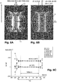
- the figures 6A, 6B, 6C and 6D represent examples, respectively, of magnetic field lines and isovalues of the field modulus of a structure according to the invention in the XY, XZ planes and the BX, BZ planes and their graphic representation.
- the figure 6E represents two examples of magnetic field lines and isovalues of the field modulus of the cylindrical magnetic structure according to the invention, in the XY and XZ planes.
- the figures 7A and 7B represent examples of magnetic field profile for, respectively, a cylindrical magnetic structure according to the prior art and a cylindrical magnetic structure according to the invention, with equivalent total mass.
- the figures 8A, 8B represent examples of maps of the isovalues of the magnetic field of a cylindrical magnetic structure according to the invention as a function of the internal radius of the second cylinder.
- the figure 9 represents examples of magnetic field lines and isovalues of the field modulus of the cylindrical magnetic structure according to the invention, with a homogeneous field zone optimized for different values of the outer radius, the inner radius and the distance between cylinders.
- the figure 10 represents examples of isovalues of the magnetic field of the second cylinder in the XZ plane for different values of its internal radius and for different widths of the cylinders.
- the figure 11 graphically represents an optimized variation of Xmax and the constant magnetic field of the figure 10 depending on the width of the cylinders and for different values of the inner radius of the second cylinder.
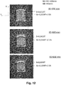
- the figure 12 represents examples of magnetic field lines and isovalues of the field modulus of the cylindrical magnetic structure of the invention, in the XY plane, for different values of external radius.
- the figure 5A shows a longitudinal sectional view of a cylindrical magnetic structure with three cylinders according to the invention.
- the figure 5B shows a view in diametral section of each of the three cylinders of the cylindrical magnetic structure according to the invention.
- This cylindrical magnetic structure 100 comprises a first cylinder 110, also called cylinder A, a second cylinder 120, also called cylinder B and a third cylinder 130, also called cylinder C.
- Each of these cylinders is a hollow cylinder, as shown in figure figure 4 , mounted around an axis of revolution Z.
- Each cylinder is defined by an interior radius RI, an exterior radius RE and a width L, the width L being the distance separating the two parallel circular bases B1, B2 of the cylinder.
- the three cylinders 110, 120, 130 are mounted ordered and aligned around the same axis of revolution Z of the three-dimensional reference frame OXYZ.
- the three cylinders 110, 120, 130 are mounted so that the second cylinder 120 is positioned between the first and the third cylinders 110, 130, one of the bases of the second cylinder 120 being opposite one of the faces of the first cylinder 110 and the other face of the second cylinder 120 being opposite one of the faces of the third cylinder 130.
- Each of the three cylinders 110, 120, 130 of the cylindrical magnetic structure is a dipolar Halbach type magnetic cylinder comprising a plurality of permanent magnets n i whose magnetic moment - that is to say the magnetization orientation - of two contiguous magnets, for example ni and n i-1 , form an angle of 360 ° / (n / 2).
- the number of ni magnets may vary.
- the modulus of the magnetic field at the center is maximum for an infinite number of magnets and it decreases as the number of magnets decreases.
- the number of magnets is 24, each magnet having a magnetic orientation offset by 30 ° with respect to the adjacent magnet. This number of 24 magnets offers a magnetic field at 96-98% of the optimum field and easy assembly and mechanical production.
- the three cylinders 110, 120, 130 have identical outer radii RE.
- the outer radius REA of the first cylinder 110, the outer radius REB of the second cylinder 120 and the radius REC of the third cylinder 130 may be, for example, between 500mm and 700mm.
- the first and third cylinders 110, 130 have an identical inner radius RI.
- RIA RIC
- RIA is the interior radius of the first cylinder 110
- RIB is the interior radius of the third cylinder 130.
- the second cylinder 120 has an interior radius RIB greater than the interior radii RIA, RIC of the first and third cylinders 110, 130.
- the first and third cylinders can have an interior radius RIA, RIC, for example, comprised between 250mm and 500mm and the second cylinder an interior radius RIB, for example, comprised between 290mm and 540mm.
- at least one of the three cylinders has an interior radius RI greater than or equal to 250mm.
- the first and third cylinders 110, 130 have an identical width L.
- LA LC
- LA the width of the first cylinder 110
- LC the width of the third cylinder 130.
- the second cylinder 120 has a width LB less than the width LA, LC of the first and third cylinders 110, 130.
- the width LB of the second cylinder 120 can be, for example, between 56mm and 170mm and the width LA, LC of the first and third cylinders 110, 130 between 60mm and 180mm.
- the three cylinders 110, 120, 130 are positioned at a substantially equal distance from each other.
- the distance dAB separating the median plane PMA of the first cylinder 110 and the median plane PMB of the second cylinder 120 is equal, to within one delta, to the distance dBC separating the median plane PMB of the second cylinder 120 and the median plane PMC of the third cylinder 130, as shown in figure 5A .
- the three cylinders can be distant, or separate, from each other.
- the homogeneity of the magnetic field in a volume ⁇ X. ⁇ Y. ⁇ Z can be quantified at +/- 1% with respect to the dimensions of the cylindrical structure by obtaining ⁇ X ⁇ RIB, ⁇ Y ⁇ RIB and ⁇ Z ⁇ RIB / 2.
- An example of the intervals ⁇ X, ⁇ Y and ⁇ Z is shown in the figure 6E .
- the cylindrical magnetic structure 100 as described above makes it possible to limit the propagation of the magnetic field lines on the outside of the cylinder and to produce an optimum homogeneous field zone, that is to say as wide as possible in the 3 directions X, Y and Z, while reducing the mass of the permanent magnets in the structure.
- This homogeneous field area is defined by field lines which are parallel and whose moduli are identical - to within a few percent (for example 1 to 2%) - in the X, Y and Z directions of the OXYZ reference frame. These field moduli, when they are identical, are called isovalues.
- the figure 6D represents the magnetic field lines and the isovalues, in the XY plane, for two different values of Z.
- the figure 6C represents, in graphic form, the field lines 13 and the isovalues 15 in the homogeneous field zone 14.
- figure 7A shows examples of field B obtained with a single cylindrical structure of the prior art, while the figure 7B shows the fields obtained, under identical conditions, with the cylindrical magnetic structure of the invention.
- a comparison of the two figures 7A and 7B shows that the field B produced by the single cylinder exhibits a variation B (Z) of the field B in the Z direction with an intrinsic maximum in the central zone referenced 16, while the three-cylinder structure generates a constant B-field bearing for X varying between -250mm and + 250mm.
- this bearing in the examples of figure 7B is at the origin of an increase of the homogeneous field area compared to the examples of the figure 7A .
- the figure 8A represents examples of isovalues 15 in the XZ plane for internal radii RIB of the second cylinder 120 varying between 400mm and 460mm.
- the determination of the optimal internal radius RIB of the second cylinder 120 with respect to the internal radii RIA and RIC of the first and third cylinders 110, 130 corresponds to obtaining an area of constant magnetic field as large as possible according to the 3 X dimensions, Y, Z - and in particular in the XZ plane - that is to say the maximum value of X (Xmax).
- RIB RIA + 40mm, as represented on the figure 8B .
- FIG 9 shows examples of field lines 13 and isovalues of the field modulus for a cylindrical magnetic structure with 3 cylinders with a homogeneous field zone optimized for different values of outer radius RE, inner radius RI and distance between cylinder dAB, dBC , that is, values verifying the two equations above.
- the figure 11 graphically represents the variations of optimized Xmax and constant magnetic field B of the figure 10 as a function of the width LA of the first and third cylinders for different values of the internal radius RIB of the second cylinder.
- the value of the field increases, or on the contrary decreases, when the outer radii REA, REB, REC of the first, second and third cylinders increases or, respectively, decreases.
- the determination of the interior radii RIA, RIC, RIB is not modified by the variation of the exterior radius RE of the cylinders and that the homogeneity and the constancy of the magnetic field are independent of the exterior radius.
- the increase (respectively the decrease) of the outer radius of the cylinders 110, 120, 130 make it possible to increase (respectively decrease) the modulus of the magnetic field inside the cylindrical magnetic structure with three cylinders without modifying the homogeneity and the constancy of the magnetic field in a volume ⁇ X. ⁇ Y. ⁇ Z.
- cylindrical magnetic structure according to the invention comprises various variants, modifications and improvements which will be evident to those skilled in the art, it being understood that these variants , modifications and improvements are within the scope of the invention.
Landscapes
- Physics & Mathematics (AREA)
- Health & Medical Sciences (AREA)
- Engineering & Computer Science (AREA)
- Nuclear Medicine, Radiotherapy & Molecular Imaging (AREA)
- Life Sciences & Earth Sciences (AREA)
- General Physics & Mathematics (AREA)
- Power Engineering (AREA)
- Biomedical Technology (AREA)
- Electromagnetism (AREA)
- Radiology & Medical Imaging (AREA)
- Condensed Matter Physics & Semiconductors (AREA)
- Animal Behavior & Ethology (AREA)
- General Health & Medical Sciences (AREA)
- Public Health (AREA)
- Veterinary Medicine (AREA)
- Dynamo-Electric Clutches, Dynamo-Electric Brakes (AREA)
- Hard Magnetic Materials (AREA)
- Permanent Field Magnets Of Synchronous Machinery (AREA)
Description
- La présente invention concerne une structure magnétique cylindrique de type Halbach dipolaire permettant de produire une zone de champ magnétique sensiblement homogène, c'est-à-dire avec des lignes de champ magnétique sensiblement parallèles et sensiblement constantes en module. On entend par « sensiblement » des valeurs de module à +/- 5% et des variations d'orientation de lignes à +/- 1°.
- L'invention trouve des applications dans tous les domaines nécessitant des structures magnétiques de grandes dimensions avec une zone de champ magnétique sensiblement homogène. Elle trouve en particulier des applications pour la production de mémoires magnétiques de type MRAM. Elle trouve également des applications dans le domaine médical pour la destruction de cellules cancéreuses par vibrations magnéto-mécaniques et pour l'imagerie par résonance magnétique nucléaire (RMN).
- Il est connu d'utiliser des structures magnétiques cylindriques de type Halbach dipolaire pour générer des lignes de champ magnétique d'une grande homogénéité, c'est-à-dire des lignes de champ parallèles dont les modules sont sensiblement constants.
- Il est, en particulier, connu d'utiliser des structures magnétiques cylindriques en aimants permanents de grandes dimensions pour différentes applications telles que la production de mémoires magnétiques de type MRAM (Magnetic Random Access Memory, en termes anglo-saxons) pour orienter parallèlement les domaines ferromagnétiques des électrodes (états parallèles/antiparallèles séparés par une barrière tunnel) par un recuit dans un champ magnétique homogène et de forte intensité. Le document « Magnetoresistive Random Access Memory» de D.Apalkov, B. Dieny et J.M. Slaughter, dans Proceeding of the IEEE, Vol.104, No10, Octobre 2016, décrit un exemple de réalisation d'une telle mémoire MRAM.
- Pour une telle application, la structure magnétique cylindrique doit généralement être de grandes dimensions et présenter un rayon intérieur de plusieurs dizaines de centimètres. Un exemple d'une telle structure est décrit notamment dans l'article « Development of world'slargest Halbach - type magnetic circuit » de Shin-Etsu dans Rare Earth Magnets, Japan. La structure décrite dans cet article présente un diamètre intérieur de 50cm, un diamètre extérieur de 140cm, une largeur de 100cm et un poids de 10T. Une telle structure, particulièrement lourde et encombrante, permet la production d'un champ magnétique constant à 2.8% i.e. 1.05T+/-0.0294T ou de 1.02T à 1.08T.
- Il est également connu d'utiliser des structures magnétiques cylindriques en aimants permanents de grandes dimensions pour des applications médicales telles que la cancérologie. Dans une telle application, la structure magnétique cylindrique comporte généralement un diamètre intérieur de 40 à 80cm pour permettre de traiter des patients (passage du corps ou au moins la tête pour le traitement du glioblastome) et produit un champ magnétique homogène de 30mT à 1 T suivant les cas. La structure magnétique cylindrique est mise en rotation à faible fréquence (typiquement 20HZ) afin de détruire les cellules cancéreuses par vibration magnéto-mécanique des microparticules magnétiques greffées sur des cellules, comme cela est décrit dans les documents suivants : « Triggering the apoptosis of targeted human renal cancer cells by the vibration of anisotropic magnetic particles attached to the cell membrane », S. Leulmi et al., Nanoscale, 2015,7,15904-15914 et « Rotating magnetic field induced oscillation of magnetic particles for in vivo mechanical destruction of malignant glioma », Y. Cheng et al., Journal of Controlled Release, 223 (2016) 75-84.
- Des structures magnétiques cylindriques à champ homogène fixe ou en rotation peuvent aussi être utilisée dans l'imagerie par résonance magnétique nucléaire (RMN) comme décrit notamment dans les documents suivants : « System and Method for providing a rotating magnetic field », R. D. Schlueter and T. F. Budinger, United States Patent n°
US2008/0024130 A1, Jan.31,2008 et « Permanent magnet ring assembly for NMR imaging system »,S. Beer, U.S. Patent n° 4,703,276, Oct. 27,1987 . - D'autres exemples de structures magnétiques cylindriques connues pour produire une zone de champ magnétique homogène sont décrites dans les documents « The ideal dimensions of a Halbach cylinder of finite length », R. Bjork, Journal of Applied Physics, Vol.109(1), 013915, 2011, «Optimization and improvement of halbach cylinder design » de R.Bjork et al., Journal of Applied Physics 104, 013910 (2008), « Dipolar Halbach Magnet Stacks Made from Identically Shaped Permanent Magnets for Magnetic Resonance », H. Soltner and P. Blümler, Concepts in Magnetic Resonance Part A, DOI 10.1002/cmr.a, «Magic Angle Rotating Field NMR/MRI Magnet for In Vivo Monitoring of Tissue», R. D. Schlueter and T. F. Budinger, IEEE Transactions on Applied Superconductivity, vol. 18, no. 2 (June 2008), «Multipole shimming of permanent magnets using harmonic corrector rings», R. C. Jachmann et al, Review of Scientific Instruments 78, 035115 (2007) et le brevet
FR1372136 - Un exemple d'une structure magnétique cylindrique classique est représentée selon une vue en coupe longitudinale et une vue en coupe diamétrale sur la
figure 1 . Cette structure magnétique cylindrique 10 comporte un cylindre 11 de rayon intérieur RI, de rayon extérieur RE et de largeur L. Ce cylindre 11 est constitué d'une pluralité d'aimants 12 montés en couronne, contiguement les uns aux autres, deux aimants contigus présentant des orientations de moments magnétiques différents. Une telle structure magnétique cylindrique 10 produit un champ magnétique comme montré sur les cartographies desfigures 2 et3 . En particulier, lafigure 2 représente des cartographies, dans un plan XZ d'un repère tridimensionnel OXYZ et lafigure 3 représente des cartographies, dans le plan XY du même repère, de structures magnétiques cylindriques dont les largeurs L varient entre 100mm et 1000mm. Ces cartographies montrent que le champ magnétique se propageant suivant la direction X est de forme ovoïde avec des lignes de champ 13 courbes qui s'étendent, suivant la direction Z, en partie en extérieur du cylindre 10. Lafigure 2 montre qu'une zone de champ magnétique homogène ne peut être obtenue suivant la direction Z que pour une structure avec une largeur conséquente. En effet, pour une largeur L = 100mm, la zone homogène est quasi-inexistante. Une largeur L = 1000mm permet de produire la zone homogène 14 dans laquelle les lignes de champ 13 sont sensiblement parallèles et de module constant. - Toutefois, la quantité de lignes de champ intégrée dans la zone homogène 14 est petite en regard du nombre total de lignes de champs produites, un grand nombre de lignes de champs sortant du volume de la structure magnétique cylindrique. En effet, en traçant le rapport du champ magnétique au centre au champ hors axe à une distance considérée (par exemple 250mm), il apparait qu'une longueur d'environ 1 mètre est nécessaire pour obtenir une uniformité de champ à environ 5%.
- Ainsi, quelle que soit l'application considérée, la structure magnétique cylindrique doit nécessairement être de grandes dimensions pour produire une zone de champ magnétique homogène suivant les trois directions X, Y et Z. Or, non seulement une structure magnétique cylindrique de grandes dimensions est lourde (plusieurs tonnes) et encombrante (volume supérieur au m3) mais elle nécessite aussi un très gros volume d'aimants dont l'assemblage est complexe et couteux. En outre, pour des applications où la structure magnétique cylindrique doit être rotative, les moteurs assurant leur rotation doivent être particulièrement performants (puissants) ; ils sont donc particulièrement onéreux.
- Pour répondre aux problèmes évoqués ci-dessus d'encombrement, de masse, de difficulté de mise en œuvre et de coût, le demandeur propose une structure magnétique cylindrique comportant trois cylindres de révolution de type Halbach dipolaire, alignés les uns avec les autres et permettant d'obtenir une zone de champ magnétique homogène optimisée.
- L'invention concerne une structure magnétique cylindrique de révolution selon la revendication 1 produisant, dans un espace interne de ladite structure, un champ magnétique sensiblement homogène dans toutes les directions d'un repère orthonormé tridimensionnel (OXYZ) c'est-à-dire avec des lignes de champ magnétique sensiblement parallèles et sensiblement constantes en module . Cette structure se caractérise par le fait qu'elle comporte trois cylindres de révolution, creux, de type Halbach dipolaire, alignés les uns avec les autres suivant un même axe de révolution (Z), le premier, le deuxième et le troisième cylindres étant agencés comme suit :
- les premier, deuxième et troisième cylindres (110, 120, 130) sont disjoints,
- le deuxième cylindre est positionné entre le premier et le troisième cylindres,
- les premier, deuxième et troisième cylindres comportent des rayons extérieurs (REA, REB, REC) sensiblement identiques,
- la largeur (LB) du deuxième cylindre (120) est inférieure d'environ 10% aux largeurs (LA, LC) des premier et troisième cylindres, et
- le premier et le troisième cylindres comportent des rayons intérieurs (RIA, RIC) sensiblement identiques, inférieurs au rayon intérieur du deuxième cylindre (RIB),
- au moins un des trois cylindres (110, 120, 130) ayant un rayon intérieur (RI) supérieur ou égal à 250mm,
- le premier et le troisième cylindres comportent des largeurs (LA, LC) sensiblement identiques, et
- les premier, deuxième et troisième cylindres comportent chacun un plan médian, le plan médian du deuxième cylindre étant à une distance sensiblement égale du plan médian du premier cylindre et du plan médian du troisième cylindre.
- Les rayons extérieurs des premier, deuxième et troisième cylindres ainsi que les rayons intérieurs et largeurs des premier et troisième cylindres sont identiques avantageusement à 5% près.
- Cette structure magnétique cylindrique permet d'obtenir une zone de champ magnétique homogène à +/-5% et pouvant même atteindre un niveau d'homogénéité de +/-1% sur un grand volume, dans les trois directions X, Y et Z du repère orthonormé OXYZ et avec une masse de cylindre réduite.
- On appelle « zone de champ magnétique homogène » un ensemble de lignes de champ magnétique sensiblement parallèles les unes aux autres et ayant un module de champ sensiblement identique.
- Dans la suite de la description, la structure magnétique cylindrique à trois cylindres de l'invention sera appelée indifféremment structure magnétique cylindrique, structure magnétique ou simplement structure. De même, les lignes de champ magnétique et les modules de champ magnétique seront appelés indifféremment lignes de champ ou module de champ.
- De façon avantageuse, chacun des premier, deuxième et troisième cylindres de la structure magnétique cylindrique comporte un nombre n d'aimants permanents, avec n > 2, et avantageusement supérieur ou égale à 6, disposés en couronne et orientés de sorte que les moments magnétiques de deux aimants contigus forment un angle de 360°/(n/2) dans un plan (OXY) du repère tridimensionnel (OXYZ).
- De façon avantageuse, chacun des premier, deuxième et troisième cylindres de la structure comporte 24 aimants permanents disposés en couronne et orientés de sorte que les moments magnétiques de deux aimants contigus forment un angle de 30° dans le plan (OXY).
- La structure magnétique cylindrique selon l'invention peut comporter une ou plusieurs des caractéristiques suivantes :
- les distances (dAB, dBC) entre respectivement les plans médians des premier et deuxième cylindres et les plans médians des deuxième et troisième cylindres répondent à l'équation : RIA/dAB =RIA/dBC=1.5 +/- 20%.
- le rayon intérieur (RIB) du deuxième cylindre (B) est supérieur aux rayons intérieurs des premier et troisième cylindres (RIA, RIC) avec : RIB = RIA + ΔR, où ΔR = 40mm +/-10%.
- les distances (dAB, dBC) entre les plans médians de chacun des premier, deuxième et troisième cylindres sont optimales lorsque RIA/dAB = RIA/dBC = 1,5 +/- 5%.
- les lignes de champ homogènes étant parallèles et à modules sensiblement constants, la valeur du module des lignes de champ varie en fonction de la dimension des rayons extérieurs des cylindres (REA, REB, REC).
- les lignes de champ homogènes étant parallèles et à modules sensiblement constants, la valeur du module des lignes de champ varie en fonction des largeurs des premier, deuxième et troisième cylindres (LA, LB, LC).
- On appelle « plan médian » d'un cylindre de la structure selon l'invention le plan parallèle au plan (XZ) du repère OXYZ qui coupe diamétralement le cylindre et passe par le milieu de la largeur dudit cylindre.
- Dans la suite de la description, des dimensions et distances seront définies comme étant « égale(s) » ou « sensiblement égale(s) », étant entendu que cette égalité peut être approximative, à quelques millimètres près.
- D'autres avantages et caractéristiques de l'invention apparaîtront à la lecture de la description, illustrée par les figures dans lesquelles :
- La
figure 1 , déjà décrite, représente des vues en coupes longitudinale et diamétrale d'une structure magnétique cylindrique selon l'art antérieur. - Les
figures 2 et3 , déjà décrites, représentent des cartographies dans des plans, respectivement XZ et XY, des champs magnétiques produits par des structures magnétiques cylindriques selon l'art antérieur. - La
figure 4 représente un exemple d'un cylindre de la structure magnétique cylindrique selon l'invention. - Les
figures 5A et 5B représentent des vues en coupes longitudinale et diamétrale de la structure magnétique cylindrique selon l'invention. - Les
figures 6A, 6B, 6C et6D représentent des exemples, respectivement, des lignes de champ magnétique et des isovaleurs du module du champ d'une structure selon l'invention dans les plans XY, XZ et les plans BX, BZ et leur représentation graphique. - La
figure 6E représente deux exemples de lignes de champ magnétique et d'isovaleurs du module du champ de la structure magnétique cylindrique selon l'invention, dans les plans XY et XZ. - Les
figures 7A et 7B représentent des exemples de profil de champs magnétiques pour, respectivement, une structure magnétique cylindrique selon l'art antérieur et une structure magnétique cylindrique selon l'invention, à masse totale équivalente. - Les
figures 8A, 8B représentent des exemples de cartographies des isovaleurs du champ magnétique d'une structure magnétique cylindrique selon l'invention en fonction du rayon intérieur du deuxième cylindre. - La
figure 9 représente des exemples de lignes de champ magnétique et d'isovaleurs du module du champ de la structure magnétique cylindrique selon l'invention, à zone de champ homogène optimisée pour différentes valeurs du rayon extérieur, du rayon intérieur et de la distance entre cylindres. - La
figure 10 représente des exemples d'isovaleurs du champ magnétique du deuxième cylindre dans le plan XZ pour différentes valeurs de son rayon intérieur et pour différentes largeurs des cylindres. - La
figure 11 représente graphiquement une variation optimisée de Xmax et du champ magnétique constant de lafigure 10 en fonction de la largeur des cylindres et pour différentes valeurs du rayon intérieur du deuxième cylindre. - La
figure 12 représente des exemples de lignes de champ magnétique et d'isovaleurs du module du champ de la structure magnétique cylindrique de l'invention, dans le plan XY, pour différentes valeurs de rayon extérieur. - Un exemple de réalisation d'une structure magnétique cylindrique comportant trois cylindres alignés est décrit en détail ci-après, en référence aux dessins annexés. Cet exemple illustre les caractéristiques et avantages de l'invention. Il est toutefois rappelé que l'invention ne se limite pas à cet exemple.
- Sur les figures, les éléments identiques sont repérés par des références identiques. Pour des questions de lisibilité des figures, les échelles de taille entre éléments représentés ne sont pas respectées.
- La
figure 5A représente une vue en coupe longitudinale d'une structure magnétique cylindrique à trois cylindres selon l'invention. Lafigure 5B représente une vue en coupe diamétrale de chacun des trois cylindres de la structure magnétique cylindrique selon l'invention. Cette structure magnétique cylindrique 100 comporte un premier cylindre 110, appelé aussi cylindre A, un deuxième cylindre 120, appelé aussi cylindre B et un troisième cylindre 130, appelé aussi cylindre C. Chacun de ces cylindres est un cylindre creux, comme représenté sur lafigure 4 , monté autour d'un axe de révolution Z. Chaque cylindre est défini par un rayon intérieur RI, un rayon extérieur RE et une largeur L, la largeur L étant la distance séparant les deux bases circulaires parallèles B1, B2 du cylindre. - Comme représenté sur les
figures 5A, 5B , les trois cylindres 110, 120, 130 sont montés ordonnés et alignés autour du même axe de révolution Z du repère tridimensionnel OXYZ. Autrement dit, les trois cylindres 110, 120, 130 sont montés de sorte que le deuxième cylindre 120 est positionné entre le premier et le troisième cylindres 110, 130, l'une des bases du deuxième cylindre 120 étant en regard d'une des faces du premier cylindre 110 et l'autre face du deuxième cylindre 120 étant en regard d'une des faces du troisième cylindre 130. - Chacun des trois cylindres 110, 120, 130 de la structure magnétique cylindrique est un cylindre magnétique de type Halbach dipolaire comprenant une pluralité d'aimants permanents ni dont le moment magnétique - c'est-à-dire l'orientation d'aimantation - de deux aimants contigus, par exemple ni et ni-1, forme un angle de 360°/(n/2). Le nombre d'aimants ni peut varier. Le module du champ magnétique au centre est maximum pour un nombre infini d'aimants et il diminue quand le nombre d'aimants diminue. Dans l'exemple représenté sur les
figures 5A, 5B , et considéré par la suite, le nombre d'aimants est de 24, chaque aimant ayant une orientation magnétique décalée de 30° par rapport à l'aimant contigu. Ce nombre de 24 aimants offre un champ magnétique à 96-98% du champ optimum et un montage et une réalisation mécanique facilités. - Les trois cylindres 110, 120, 130 ont des rayons extérieurs RE identiques. Le rayon extérieur REA du premier cylindre 110, le rayon extérieur REB du deuxième cylindre 120 et le rayon REC du troisième cylindre 130 peuvent être, par exemple, compris entre 500mm et 700mm.
- Les premier et troisième cylindres 110, 130 présentent un rayon intérieur RI identique. Autrement dit RIA = RIC, où RIA est le rayon intérieur du premier cylindre 110 et RIB est le rayon intérieur du troisième cylindre 130. Le deuxième cylindre 120 présente un rayon intérieur RIB supérieur aux rayons intérieurs RIA, RIC des premier et troisième cylindres 110, 130. Le rayon intérieur RIB du deuxième cylindre 120 peut être défini, par exemple, par : RIB (mm) = RIA(mm) + 40mm. Ainsi, les premier et troisième cylindres peuvent avoir un rayon intérieur RIA, RIC, par exemple, compris entre 250mm et 500mm et le deuxième cylindre un rayon intérieur RIB, par exemple, compris entre 290mm et 540mm. De façon optimale, l'un au moins des trois cylindres a un rayon intérieur RI supérieur ou égal à 250mm.
- Les premier et troisième cylindres 110, 130 présentent une largeur L identique. Autrement dit LA = LC, où LA est la largeur du premier cylindre 110 et LC est la largeur du troisième cylindre 130. Selon certains modes de réalisation, le deuxième cylindre 120 présente une largeur LB inférieure à la largeur LA, LC des premier et troisième cylindres 110, 130. La largeur LB du deuxième cylindre 120 peut être définie, par exemple, par : LB(mm) = LA(mm) - 10%. Selon un exemple, la largeur LB du deuxième cylindre 120 peut être, par exemple, comprise entre 56mm et 170mm et la largeur LA, LC des premier et troisième cylindres 110, 130 comprises entre 60mm et 180mm.
- Les trois cylindres 110, 120, 130 sont positionnés à distance sensiblement égale les uns des autres. Autrement dit, la distance dAB séparant le plan médian PMA du premier cylindre 110 et le plan médian PMB du deuxième cylindre 120 est égale, à un delta près, à la distance dBC séparant le plan médian PMB du deuxième cylindre 120 et le plan médian PMC du troisième cylindre 130, comme représenté sur la
figure 5A . Plus précisément, les distances dAB et dBC entre les plans médians des trois cylindres 110, 120, 130 peuvent être définies par : RIA/dAB = RIA/dBC = 1,5 +/- 10%. - Comme représenté sur la
figure 5A , les trois cylindres peuvent être distants, ou disjoints, les uns des autres. Autrement dit les cylindres A, B, C peuvent ne pas être accolés les uns aux autres. Ils peuvent, par exemple, être positionnés à distance les uns des autres de sorte que :


- L'ajustement des rayons intérieurs RIA et RIB, avec RIA < RIB permet d'optimiser l'homogénéité du champ magnétique, cette homogénéité étant optimisée pour RIB (mm) = RIA (mm) + 40mm, comme montré dans les exemples des
figures 8A et 8B . L'homogénéité du champ magnétique dans un volume ΔX.ΔY.ΔZ peut être quantifiée à +/-1% par rapport aux dimensions de la structure cylindrique en obtenant ΔX≥RIB, ΔY≥RIB et ΔZ≥RIB/2. Un exemple des intervalles ΔX, ΔY et ΔZ est représenté sur lafigure 6E . - La structure magnétique cylindrique 100 telle que décrite précédemment permet de limiter la propagation des lignes de champ magnétique en extérieur de cylindre et produire une zone de champ homogène optimale, c'est-à-dire la plus large possible dans les 3 directions X, Y et Z, tout en réduisant la masse des aimants permanents de la structure. Cette zone de champ homogène est définie par des lignes de champ qui sont parallèles et dont les modules sont identiques - à quelques pourcents près (par exemple 1 à 2%) - dans les directions X, Y et Z du repère OXYZ. Ces modules de champ, lorsqu'ils sont identiques, sont appelés des isovaleurs.
- La
figure 6A représente des exemples de lignes de champ 13 et d'isovaleurs 15 du champ magnétique obtenu avec la structure magnétique cylindrique à 24 aimants décrite ci-dessus, dans le plan XZ, lorsque : - les trois cylindres ont un rayon extérieur RE égal à 600mm,
- les premier et troisième cylindres 110, 130 ont un rayon intérieur de 400mm et une largeur de 100mm,
- le deuxième cylindre 120 a un rayon intérieur de 440mm et une largeur de 90mm.
- La
figure 6D représente les lignes de champ magnétique et les isovaleurs, dans le plan XY, pour deux valeurs différentes de Z. Lafigure 6B représente les composantes BX et BZ du champ magnétique B suivant l'axe X pour différentes valeurs de Z. Sur un intervalle ΔX=500mm et ΔZ>250mm, la structure magnétique cylindrique ci-dessus permet d'obtenir le champ magnétiqueB =BXi avec BX=0.1320T. Lafigure 6C représente, sous forme graphique, les lignes de champs 13 et les isovaleurs 15 dans la zone de champ homogène 14. - Les
figures 7A et 7B représentent différents exemples de profils de champs magnétiques B suivant la direction Z dans un plan central où Y = 0 et pour différentes valeurs en mm de X. Lafigure 7A montre des exemples de champ B obtenus avec une structure à cylindrique unique de l'art antérieur, tandis que lafigure 7B montre les champs obtenus, dans des conditions identiques, avec la structure magnétique cylindrique de l'invention. Une comparaison des deuxfigures 7A et 7B montre que le champ B produit par le cylindre unique présente une variation B(Z) du champ B dans la direction Z avec un maximum intrinsèque dans la zone centrale référencée 16, alors que la structure à trois cylindres génère un palier à champ B constant pour X variant entre -250mm et + 250mm. L'homme du métier comprendra que l'existence de ce palier dans les exemples de lafigure 7B est à l'origine d'une augmentation de la zone de champ homogène par rapport aux exemples de lafigure 7A . - La
figure 8A représente des exemples d'isovaleurs 15 dans le plan XZ pour des rayons intérieurs RIB du deuxième cylindre 120 variant entre 400mm et 460mm. La détermination du rayon interne RIB optimal du deuxième cylindre 120 par rapport aux rayons internes RIA et RIC des premier et troisième cylindres 110, 130 correspond à l'obtention d'une zone de champ magnétique constant la plus grande possible suivant les 3 dimensions X, Y, Z - et en particulier dans le plan XZ - c'est-à-dire la valeur maximale de X (Xmax). En traçant la valeur de Xmax en fonction du rayon RIB, on obtient une valeur optimale : RIB = RIA + 40mm, comme représenté sur lafigure 8B . - D'une façon plus générale, en faisant varier les rayons intérieurs RIA, RIC et RIB ainsi que la distance entre cylindre dAB, dBC, on obtient les paramètres qui permettent d'obtenir une zone homogène optimale :


figure 9 représente des exemples de lignes de champ 13 et d'isovaleurs du module du champ pour une structure magnétique cylindrique à 3 cylindres à zone de champ homogène optimisées pour différentes valeurs de rayon extérieur RE, de rayon intérieur RI et de distance entre cylindre dAB, dBC, c'est-à-dire des valeurs vérifiant les deux équations ci-dessus. - La
figure 10 représente plusieurs exemples de cartographies d'isovaleurs du champ magnétique B dans le plan XZ pour différentes valeurs du rayon interne RIB du deuxième cylindre 120 qui vérifient RIB = RIA + 40mm et lorsque la largeur du deuxième cylindre varie entre 56mm et 170mm. Ces différents exemples montrent que la valeur du module du champ augmente, ou au contraire diminue, lorsque les largeurs LA, LB, LC des premier, deuxième et troisième cylindres augmente ou, respectivement, diminue. Lafigure 11 représente graphiquement les variations de Xmax optimisé et du champ magnétique B constant de lafigure 10 en fonction de la largeur LA des premier et troisième cylindres pour différentes valeurs du rayon intérieur RIB du deuxième cylindre. Ces cartographies et graphiques montrent que la détermination des rayons intérieurs RIA, RIC, RIB n'est pas modifiée par la variation des largeurs LA, LB, LC des cylindres et que l'homogénéité et la constance du champ magnétique sont indépendantes des largeurs des cylindres. Autrement dit, l'augmentation (respectivement la diminution) de la largeur des cylindres 110, 120, 130 permet d'augmenter (respectivement de diminuer) le module du champ magnétique à l'intérieur de la structure magnétique cylindrique à trois cylindres sans modifier l'homogénéité et la constance du champ magnétique dans un volume ΔX.ΔY.ΔZ. - La
figure 12 représente des exemples de lignes de champ magnétique et d'isovaleurs du module du champ de la structure magnétique cylindrique à trois cylindres de l'invention, dans le plan XY, en faisant varier le rayon extérieur RE de 550mm à 650 mm et avec des rayons intérieurs RIA=RIC=400mm et RIB=440mm. Ces différents exemples montrent que la valeur du champ augmente, ou au contraire diminue, lorsque les rayons extérieurs REA, REB, REC des premier, deuxième et troisième cylindres augmente ou, respectivement, diminue. Ces exemples montrent en outre que la détermination des rayons intérieurs RIA, RIC, RIB n'est pas modifiée par la variation du rayon extérieur RE des cylindres et que l'homogénéité et la constance du champ magnétique sont indépendantes du rayon extérieur. Autrement dit, l'augmentation (respectivement la diminution) du rayon extérieur des cylindres 110, 120, 130 permet d'augmenter (respectivement de diminuer) le module du champ magnétique à l'intérieur de la structure magnétique cylindrique à trois cylindres sans modifier l'homogénéité et la constance du champ magnétique dans un volume ΔX.ΔY.ΔZ. - Bien que décrit à travers un certain nombre d'exemples, variantes et modes de réalisation, la structure magnétique cylindrique selon l'invention comprend divers variantes, modifications et perfectionnements qui apparaîtront de façon évidente à l'homme du métier, étant entendu que ces variantes, modifications et perfectionnements font partie de la portée de l'invention.
Claims (8)
- Structure magnétique cylindrique de révolution (100) produisant, dans un espace interne de ladite structure, un champ magnétique (13) sensiblement homogène dans toutes les directions d'un repère orthonormé tridimensionnel (OXYZ),
caractérisée en ce qu'elle comporte trois cylindres de révolution (110, 120, 130), creux, de type Halbach dipolaire, alignés les uns avec les autres suivant un même axe de révolution (Z), le premier (110), le deuxième (120) et le troisième (130) cylindres étant agencés comme suit :- les premier, deuxième et troisième cylindres (110, 120, 130) sont disjoints,- le deuxième cylindre (120) est positionné entre le premier et le troisième cylindres (110, 130),- les premier, deuxième et troisième cylindres (110, 120, 130) comportent des rayons extérieurs (REA, REB, REC) sensiblement identiques,- le premier et le troisième cylindres (110, 130) comportent des rayons intérieurs (RIA, RIC) sensiblement identiques, inférieurs au rayon intérieur (RIB) du deuxième cylindre (120),- au moins un des trois cylindres (110, 120, 130) a un rayon intérieur (RI) supérieur ou égal à 250mm,- le premier et le troisième cylindres (110, 130) comportent des largeurs (LA, LC) sensiblement identiques,- la largeur (LB) du deuxième cylindre (120) est inférieure d'environ 10% aux largeurs (LA, LC) des premier et troisième cylindres, et- les premier, deuxième et troisième cylindres (110, 120, 130) comportent chacun un plan médian (PMA, PMB, PMC), le plan médian (PMB) du deuxième cylindre (120) étant à une distance sensiblement égale du plan médian (PMA) du premier cylindre et du plan médian (PMC) du troisième cylindre. - Structure magnétique selon la revendication 1, caractérisée en ce que chacun des premier, deuxième et troisième cylindres (110, 120, 130) comporte un nombre n d'aimants permanents, avec n > 2 et avantageusement supérieur ou égale à 6, disposés en couronne et orientés de sorte que les moments magnétiques de deux aimants contigus forment un angle de 360°/(n/2) dans un plan (XY) du repère tridimensionnel (OXYZ).
- Structure magnétique selon la revendication 2, caractérisée en ce que chacun des premier, deuxième et troisième cylindres (110, 120, 130) comporte 24 aimants permanents disposés en couronne et orientés de sorte que les moments magnétiques de deux aimants contigus forment un angle de 30° dans le plan (XY).
- Structure magnétique selon l'une quelconque des revendications 1 à 3, caractérisée en ce que les distances (dAB, dBC) entre respectivement les plans médians (PMA, PMB) des premier et deuxième cylindres (110, 120) et les plans médians (PMB, PMC) des deuxième et troisième cylindres répondent à l'équation : RIA/dAB =RIA/dBC=1.5 +/- 20%.
- Structure magnétique selon l'une quelconque des revendications 1 à 4, caractérisée en ce que le rayon intérieur (RIB) du deuxième cylindre (120) est supérieur aux rayons intérieurs (RIA, RIC) des premier et troisième cylindres (110, 130) avec : RIB = RIA + ΔR, où ΔR = 40mm +/-10%.
- Structure magnétique selon l'une quelconque des revendications 1 à 5, caractérisée en ce que les distances (dAB, dBC) entre les plans médians de chacun des premier, deuxième et troisième cylindres (110, 120, 130) sont optimales lorsque RIA/dAB = RIA/dBC = 1,5 +/- 5%.
- Structure magnétique selon l'une quelconque des revendications 1 à 6, dans laquelle les lignes de champ homogènes (13) sont parallèles et à modules sensiblement constants, caractérisée en ce que la valeur du module du champ est déterminée par la dimension des rayons extérieurs (REA, REB, REC) des premier, deuxième et troisième cylindres, la valeur du module du champ étant augmentée lorsque la dimension des rayons extérieurs (REA, REB, REC) des premier, deuxième et troisième cylindres augmente et diminuée lorsque la dimension des rayons extérieurs (REA, REB, REC) des premier, deuxième et troisième cylindres diminue.
- Structure magnétique selon l'une quelconque des revendications 1 à 7, dans laquelle les lignes de champ homogènes (13) sont parallèles et à modules sensiblement constants, caractérisée en ce que la valeur du module du champ est déterminée par la largeur (LA, LB, LC) des premier, deuxième et troisième cylindres, la valeur du module du champ étant augmentée lorsque la largeur (LA, LB, LC) des premier, deuxième et troisième cylindres augmente et diminuée lorsque la largeur (LA, LB, LC) des premier, deuxième et troisième cylindres diminue.
Applications Claiming Priority (1)
| Application Number | Priority Date | Filing Date | Title |
|---|---|---|---|
| FR1855073A FR3082316B1 (fr) | 2018-06-11 | 2018-06-11 | Structure magnetique cylindrique de type halbach dipolaire |
Publications (2)
| Publication Number | Publication Date |
|---|---|
| EP3582238A1 EP3582238A1 (fr) | 2019-12-18 |
| EP3582238B1 true EP3582238B1 (fr) | 2020-12-30 |
Family
ID=64049318
Family Applications (1)
| Application Number | Title | Priority Date | Filing Date |
|---|---|---|---|
| EP19179145.8A Active EP3582238B1 (fr) | 2018-06-11 | 2019-06-07 | Structure magnétique cylindrique de type halbach dipolaire |
Country Status (2)
| Country | Link |
|---|---|
| EP (1) | EP3582238B1 (fr) |
| FR (1) | FR3082316B1 (fr) |
Families Citing this family (1)
| Publication number | Priority date | Publication date | Assignee | Title |
|---|---|---|---|---|
| CN118645329B (zh) * | 2024-08-15 | 2024-10-25 | 兰州大学 | 一种磁体和磁锚定手术器械 |
Family Cites Families (4)
| Publication number | Priority date | Publication date | Assignee | Title |
|---|---|---|---|---|
| FR1372136A (fr) * | 1962-10-04 | 1964-09-11 | Siemens Ag | Système d'aimants permanents, notamment pour les tubes à ondes progressives de grande puissance |
| US4703276A (en) | 1985-04-24 | 1987-10-27 | Elscint Ltd. | Permanent magnet ring assembly for NMR imaging system and method for using such assembly |
| DE69128758T2 (de) * | 1990-10-04 | 1998-05-14 | Shinetsu Chemical Co | Zylindrische Magnetanordnung geeignet für die Bilderzeugung mittels magnetischer Kernresonanz |
| WO2006047580A2 (fr) | 2004-10-26 | 2006-05-04 | Univ California | Systeme et procede de generation d'un champ magnetique rotatif |
-
2018
- 2018-06-11 FR FR1855073A patent/FR3082316B1/fr not_active Expired - Fee Related
-
2019
- 2019-06-07 EP EP19179145.8A patent/EP3582238B1/fr active Active
Non-Patent Citations (1)
| Title |
|---|
| None * |
Also Published As
| Publication number | Publication date |
|---|---|
| FR3082316A1 (fr) | 2019-12-13 |
| EP3582238A1 (fr) | 2019-12-18 |
| FR3082316B1 (fr) | 2020-10-16 |
Similar Documents
| Publication | Publication Date | Title |
|---|---|---|
| EP2470923B1 (fr) | Structure aimantée induisant en son centre un champ homogène d'orientation prédéterminée | |
| EP2470921B1 (fr) | Dispositif d'aimant permanent cylindrique produisant un champ magnétique contrôlé à une distance de sa surface | |
| WO1988002924A1 (fr) | Aimant permanent cylindrique a champ induit longitudinal | |
| EP3582238B1 (fr) | Structure magnétique cylindrique de type halbach dipolaire | |
| WO2010116102A1 (fr) | Oscillateur radiofréquence à vanne de spin ou à jonction tunnel, procédé d'ajustement de la fréquence d'un tel oscillateur et réseau constitué d'une pluralité de tels oscillateurs | |
| FR2997243A1 (fr) | Dispositif de rotor de machine electrique rotative | |
| FR2945848A1 (fr) | Pivot traversant a elements flexibles et engin spatial comportant un tel pivot | |
| CA2475352C (fr) | Piege a ions a aimant permanent et spectrometre de masse utilisant un tel aimant | |
| EP3192106A1 (fr) | Système de génération de skyrmions | |
| EP0346333A1 (fr) | Dispositif correcteur par elements magnetiques d'inhomogeneites du champ magnetique dans un aimant. | |
| WO1988002923A1 (fr) | Aimant permanent cylindrique pour produire un champ d'induction uniforme et transverse | |
| FR2795524A1 (fr) | Dispositif de mesure rmn portable | |
| EP2593806B1 (fr) | Dispositif d'aimant permanent de creation d'un champ magnetique homogene deporte | |
| FR2949601A1 (fr) | Dispositif d'aimant permanent cylindrique a champ magnetique induit d'orientation predeterminee et procede de fabrication | |
| EP2710714B1 (fr) | Turbine génératrice de courant électrique | |
| CA2576774C (fr) | Piege a ions a aimant permanent longitudinal et spectrometre de masse utilisant un tel aimant | |
| FR2970113A1 (fr) | Dispositif de generation d'ondes hyperfrequence comprenant une pluralite de magnetrons | |
| EP1952170B1 (fr) | Machine de rmn a bobines de gradient solenoidales | |
| EP1952171B1 (fr) | Machine de rmn a bobines de gradient solenoidales incorporees dans des tubes | |
| EP2580766A1 (fr) | Oscillateur a transfert de spin | |
| EP0033704A1 (fr) | Système de bobines électromagnétiques pour l'examen de corps humains au moyen de la résonance magnétique nucléaire, et appareil d'imagerie du corps humain utilisant un tel système | |
| FR3109903A1 (fr) | Barre d’alésage munie d’actionneurs électrodynamiques pour contrer les vibrations et machine-outil munie d’une telle barre. | |
| FR3049714B1 (fr) | Procede de controle de la repartition du champ magnetique radiofrequence dans un systeme d’imagerie par resonance magnetique | |
| WO2023072608A1 (fr) | Dispositif radiofréquence pour un système d'imagerie par résonance magnétique | |
| EP3771778A1 (fr) | Dispositif de liaison ajustable |
Legal Events
| Date | Code | Title | Description |
|---|---|---|---|
| PUAI | Public reference made under article 153(3) epc to a published international application that has entered the european phase |
Free format text: ORIGINAL CODE: 0009012 |
|
| STAA | Information on the status of an ep patent application or granted ep patent |
Free format text: STATUS: REQUEST FOR EXAMINATION WAS MADE |
|
| 17P | Request for examination filed |
Effective date: 20190607 |
|
| AK | Designated contracting states |
Kind code of ref document: A1 Designated state(s): AL AT BE BG CH CY CZ DE DK EE ES FI FR GB GR HR HU IE IS IT LI LT LU LV MC MK MT NL NO PL PT RO RS SE SI SK SM TR |
|
| AX | Request for extension of the european patent |
Extension state: BA ME |
|
| RBV | Designated contracting states (corrected) |
Designated state(s): AL AT BE BG CH CY CZ DE DK EE ES FI FR GB GR HR HU IE IS IT LI LT LU LV MC MK MT NL NO PL PT RO RS SE SI SK SM TR |
|
| GRAP | Despatch of communication of intention to grant a patent |
Free format text: ORIGINAL CODE: EPIDOSNIGR1 |
|
| STAA | Information on the status of an ep patent application or granted ep patent |
Free format text: STATUS: GRANT OF PATENT IS INTENDED |
|
| RIC1 | Information provided on ipc code assigned before grant |
Ipc: H01F 7/02 20060101AFI20200701BHEP Ipc: A61N 2/06 20060101ALI20200701BHEP Ipc: H01F 3/10 20060101ALN20200701BHEP Ipc: G11C 11/02 20060101ALI20200701BHEP Ipc: G01R 33/383 20060101ALI20200701BHEP |
|
| INTG | Intention to grant announced |
Effective date: 20200724 |
|
| GRAS | Grant fee paid |
Free format text: ORIGINAL CODE: EPIDOSNIGR3 |
|
| GRAA | (expected) grant |
Free format text: ORIGINAL CODE: 0009210 |
|
| STAA | Information on the status of an ep patent application or granted ep patent |
Free format text: STATUS: THE PATENT HAS BEEN GRANTED |
|
| AK | Designated contracting states |
Kind code of ref document: B1 Designated state(s): AL AT BE BG CH CY CZ DE DK EE ES FI FR GB GR HR HU IE IS IT LI LT LU LV MC MK MT NL NO PL PT RO RS SE SI SK SM TR |
|
| REG | Reference to a national code |
Ref country code: GB Ref legal event code: FG4D Free format text: NOT ENGLISH |
|
| REG | Reference to a national code |
Ref country code: AT Ref legal event code: REF Ref document number: 1350750 Country of ref document: AT Kind code of ref document: T Effective date: 20210115 |
|
| REG | Reference to a national code |
Ref country code: DE Ref legal event code: R096 Ref document number: 602019001959 Country of ref document: DE |
|
| REG | Reference to a national code |
Ref country code: IE Ref legal event code: FG4D Free format text: LANGUAGE OF EP DOCUMENT: FRENCH |
|
| PG25 | Lapsed in a contracting state [announced via postgrant information from national office to epo] |
Ref country code: GR Free format text: LAPSE BECAUSE OF FAILURE TO SUBMIT A TRANSLATION OF THE DESCRIPTION OR TO PAY THE FEE WITHIN THE PRESCRIBED TIME-LIMIT Effective date: 20210331 Ref country code: NO Free format text: LAPSE BECAUSE OF FAILURE TO SUBMIT A TRANSLATION OF THE DESCRIPTION OR TO PAY THE FEE WITHIN THE PRESCRIBED TIME-LIMIT Effective date: 20210330 Ref country code: RS Free format text: LAPSE BECAUSE OF FAILURE TO SUBMIT A TRANSLATION OF THE DESCRIPTION OR TO PAY THE FEE WITHIN THE PRESCRIBED TIME-LIMIT Effective date: 20201230 Ref country code: FI Free format text: LAPSE BECAUSE OF FAILURE TO SUBMIT A TRANSLATION OF THE DESCRIPTION OR TO PAY THE FEE WITHIN THE PRESCRIBED TIME-LIMIT Effective date: 20201230 |
|
| REG | Reference to a national code |
Ref country code: AT Ref legal event code: MK05 Ref document number: 1350750 Country of ref document: AT Kind code of ref document: T Effective date: 20201230 |
|
| PG25 | Lapsed in a contracting state [announced via postgrant information from national office to epo] |
Ref country code: LV Free format text: LAPSE BECAUSE OF FAILURE TO SUBMIT A TRANSLATION OF THE DESCRIPTION OR TO PAY THE FEE WITHIN THE PRESCRIBED TIME-LIMIT Effective date: 20201230 Ref country code: SE Free format text: LAPSE BECAUSE OF FAILURE TO SUBMIT A TRANSLATION OF THE DESCRIPTION OR TO PAY THE FEE WITHIN THE PRESCRIBED TIME-LIMIT Effective date: 20201230 Ref country code: BG Free format text: LAPSE BECAUSE OF FAILURE TO SUBMIT A TRANSLATION OF THE DESCRIPTION OR TO PAY THE FEE WITHIN THE PRESCRIBED TIME-LIMIT Effective date: 20210330 |
|
| REG | Reference to a national code |
Ref country code: NL Ref legal event code: MP Effective date: 20201230 |
|
| PG25 | Lapsed in a contracting state [announced via postgrant information from national office to epo] |
Ref country code: HR Free format text: LAPSE BECAUSE OF FAILURE TO SUBMIT A TRANSLATION OF THE DESCRIPTION OR TO PAY THE FEE WITHIN THE PRESCRIBED TIME-LIMIT Effective date: 20201230 |
|
| REG | Reference to a national code |
Ref country code: LT Ref legal event code: MG9D |
|
| PG25 | Lapsed in a contracting state [announced via postgrant information from national office to epo] |
Ref country code: LT Free format text: LAPSE BECAUSE OF FAILURE TO SUBMIT A TRANSLATION OF THE DESCRIPTION OR TO PAY THE FEE WITHIN THE PRESCRIBED TIME-LIMIT Effective date: 20201230 Ref country code: RO Free format text: LAPSE BECAUSE OF FAILURE TO SUBMIT A TRANSLATION OF THE DESCRIPTION OR TO PAY THE FEE WITHIN THE PRESCRIBED TIME-LIMIT Effective date: 20201230 Ref country code: PT Free format text: LAPSE BECAUSE OF FAILURE TO SUBMIT A TRANSLATION OF THE DESCRIPTION OR TO PAY THE FEE WITHIN THE PRESCRIBED TIME-LIMIT Effective date: 20210430 Ref country code: CZ Free format text: LAPSE BECAUSE OF FAILURE TO SUBMIT A TRANSLATION OF THE DESCRIPTION OR TO PAY THE FEE WITHIN THE PRESCRIBED TIME-LIMIT Effective date: 20201230 Ref country code: EE Free format text: LAPSE BECAUSE OF FAILURE TO SUBMIT A TRANSLATION OF THE DESCRIPTION OR TO PAY THE FEE WITHIN THE PRESCRIBED TIME-LIMIT Effective date: 20201230 Ref country code: SK Free format text: LAPSE BECAUSE OF FAILURE TO SUBMIT A TRANSLATION OF THE DESCRIPTION OR TO PAY THE FEE WITHIN THE PRESCRIBED TIME-LIMIT Effective date: 20201230 |
|
| PG25 | Lapsed in a contracting state [announced via postgrant information from national office to epo] |
Ref country code: PL Free format text: LAPSE BECAUSE OF FAILURE TO SUBMIT A TRANSLATION OF THE DESCRIPTION OR TO PAY THE FEE WITHIN THE PRESCRIBED TIME-LIMIT Effective date: 20201230 Ref country code: AT Free format text: LAPSE BECAUSE OF FAILURE TO SUBMIT A TRANSLATION OF THE DESCRIPTION OR TO PAY THE FEE WITHIN THE PRESCRIBED TIME-LIMIT Effective date: 20201230 |
|
| PG25 | Lapsed in a contracting state [announced via postgrant information from national office to epo] |
Ref country code: IS Free format text: LAPSE BECAUSE OF FAILURE TO SUBMIT A TRANSLATION OF THE DESCRIPTION OR TO PAY THE FEE WITHIN THE PRESCRIBED TIME-LIMIT Effective date: 20210430 |
|
| REG | Reference to a national code |
Ref country code: DE Ref legal event code: R097 Ref document number: 602019001959 Country of ref document: DE |
|
| PG25 | Lapsed in a contracting state [announced via postgrant information from national office to epo] |
Ref country code: AL Free format text: LAPSE BECAUSE OF FAILURE TO SUBMIT A TRANSLATION OF THE DESCRIPTION OR TO PAY THE FEE WITHIN THE PRESCRIBED TIME-LIMIT Effective date: 20201230 Ref country code: IT Free format text: LAPSE BECAUSE OF FAILURE TO SUBMIT A TRANSLATION OF THE DESCRIPTION OR TO PAY THE FEE WITHIN THE PRESCRIBED TIME-LIMIT Effective date: 20201230 |
|
| PLBE | No opposition filed within time limit |
Free format text: ORIGINAL CODE: 0009261 |
|
| STAA | Information on the status of an ep patent application or granted ep patent |
Free format text: STATUS: NO OPPOSITION FILED WITHIN TIME LIMIT |
|
| PG25 | Lapsed in a contracting state [announced via postgrant information from national office to epo] |
Ref country code: DK Free format text: LAPSE BECAUSE OF FAILURE TO SUBMIT A TRANSLATION OF THE DESCRIPTION OR TO PAY THE FEE WITHIN THE PRESCRIBED TIME-LIMIT Effective date: 20201230 |
|
| 26N | No opposition filed |
Effective date: 20211001 |
|
| PG25 | Lapsed in a contracting state [announced via postgrant information from national office to epo] |
Ref country code: MC Free format text: LAPSE BECAUSE OF FAILURE TO SUBMIT A TRANSLATION OF THE DESCRIPTION OR TO PAY THE FEE WITHIN THE PRESCRIBED TIME-LIMIT Effective date: 20201230 Ref country code: ES Free format text: LAPSE BECAUSE OF FAILURE TO SUBMIT A TRANSLATION OF THE DESCRIPTION OR TO PAY THE FEE WITHIN THE PRESCRIBED TIME-LIMIT Effective date: 20201230 |
|
| PG25 | Lapsed in a contracting state [announced via postgrant information from national office to epo] |
Ref country code: SI Free format text: LAPSE BECAUSE OF FAILURE TO SUBMIT A TRANSLATION OF THE DESCRIPTION OR TO PAY THE FEE WITHIN THE PRESCRIBED TIME-LIMIT Effective date: 20201230 |
|
| REG | Reference to a national code |
Ref country code: BE Ref legal event code: MM Effective date: 20210630 |
|
| PG25 | Lapsed in a contracting state [announced via postgrant information from national office to epo] |
Ref country code: LU Free format text: LAPSE BECAUSE OF NON-PAYMENT OF DUE FEES Effective date: 20210607 |
|
| PG25 | Lapsed in a contracting state [announced via postgrant information from national office to epo] |
Ref country code: IE Free format text: LAPSE BECAUSE OF NON-PAYMENT OF DUE FEES Effective date: 20210607 |
|
| PG25 | Lapsed in a contracting state [announced via postgrant information from national office to epo] |
Ref country code: IS Free format text: LAPSE BECAUSE OF FAILURE TO SUBMIT A TRANSLATION OF THE DESCRIPTION OR TO PAY THE FEE WITHIN THE PRESCRIBED TIME-LIMIT Effective date: 20210430 |
|
| PG25 | Lapsed in a contracting state [announced via postgrant information from national office to epo] |
Ref country code: BE Free format text: LAPSE BECAUSE OF NON-PAYMENT OF DUE FEES Effective date: 20210630 |
|
| REG | Reference to a national code |
Ref country code: CH Ref legal event code: PL |
|
| PG25 | Lapsed in a contracting state [announced via postgrant information from national office to epo] |
Ref country code: LI Free format text: LAPSE BECAUSE OF NON-PAYMENT OF DUE FEES Effective date: 20220630 Ref country code: CH Free format text: LAPSE BECAUSE OF NON-PAYMENT OF DUE FEES Effective date: 20220630 |
|
| PG25 | Lapsed in a contracting state [announced via postgrant information from national office to epo] |
Ref country code: NL Free format text: LAPSE BECAUSE OF NON-PAYMENT OF DUE FEES Effective date: 20201230 Ref country code: CY Free format text: LAPSE BECAUSE OF FAILURE TO SUBMIT A TRANSLATION OF THE DESCRIPTION OR TO PAY THE FEE WITHIN THE PRESCRIBED TIME-LIMIT Effective date: 20201230 |
|
| PG25 | Lapsed in a contracting state [announced via postgrant information from national office to epo] |
Ref country code: SM Free format text: LAPSE BECAUSE OF FAILURE TO SUBMIT A TRANSLATION OF THE DESCRIPTION OR TO PAY THE FEE WITHIN THE PRESCRIBED TIME-LIMIT Effective date: 20201230 Ref country code: HU Free format text: LAPSE BECAUSE OF FAILURE TO SUBMIT A TRANSLATION OF THE DESCRIPTION OR TO PAY THE FEE WITHIN THE PRESCRIBED TIME-LIMIT; INVALID AB INITIO Effective date: 20190607 |
|
| PG25 | Lapsed in a contracting state [announced via postgrant information from national office to epo] |
Ref country code: MK Free format text: LAPSE BECAUSE OF FAILURE TO SUBMIT A TRANSLATION OF THE DESCRIPTION OR TO PAY THE FEE WITHIN THE PRESCRIBED TIME-LIMIT Effective date: 20201230 |
|
| PG25 | Lapsed in a contracting state [announced via postgrant information from national office to epo] |
Ref country code: TR Free format text: LAPSE BECAUSE OF FAILURE TO SUBMIT A TRANSLATION OF THE DESCRIPTION OR TO PAY THE FEE WITHIN THE PRESCRIBED TIME-LIMIT Effective date: 20201230 |
|
| PG25 | Lapsed in a contracting state [announced via postgrant information from national office to epo] |
Ref country code: MT Free format text: LAPSE BECAUSE OF FAILURE TO SUBMIT A TRANSLATION OF THE DESCRIPTION OR TO PAY THE FEE WITHIN THE PRESCRIBED TIME-LIMIT Effective date: 20201230 |
|
| PGFP | Annual fee paid to national office [announced via postgrant information from national office to epo] |
Ref country code: DE Payment date: 20250618 Year of fee payment: 7 |
|
| PGFP | Annual fee paid to national office [announced via postgrant information from national office to epo] |
Ref country code: GB Payment date: 20250625 Year of fee payment: 7 |
|
| PGFP | Annual fee paid to national office [announced via postgrant information from national office to epo] |
Ref country code: FR Payment date: 20250623 Year of fee payment: 7 |