EP3582242B1 - Dispositif de commutation électrique - Google Patents
Dispositif de commutation électrique Download PDFInfo
- Publication number
- EP3582242B1 EP3582242B1 EP18305740.5A EP18305740A EP3582242B1 EP 3582242 B1 EP3582242 B1 EP 3582242B1 EP 18305740 A EP18305740 A EP 18305740A EP 3582242 B1 EP3582242 B1 EP 3582242B1
- Authority
- EP
- European Patent Office
- Prior art keywords
- contact
- movable contact
- contact element
- axis
- rotation
- Prior art date
- Legal status (The legal status is an assumption and is not a legal conclusion. Google has not performed a legal analysis and makes no representation as to the accuracy of the status listed.)
- Active
Links
Images


Classifications
-
- H—ELECTRICITY
- H01—ELECTRIC ELEMENTS
- H01H—ELECTRIC SWITCHES; RELAYS; SELECTORS; EMERGENCY PROTECTIVE DEVICES
- H01H23/00—Tumbler or rocker switches, i.e. switches characterised by being operated by rocking an operating member in the form of a rocker button
- H01H23/02—Details
- H01H23/12—Movable parts; Contacts mounted thereon
- H01H23/16—Driving mechanisms
- H01H23/20—Driving mechanisms having snap action
- H01H23/205—Driving mechanisms having snap action using a compression spring between tumbler and an articulated contact plate
Definitions
- the invention relates to the field of electrical switches or electrical switch devices commonly used in domestic, commercial and industrial wiring installations.
- Switches comprising a so-called "see-saw” mechanism are known from prior art.
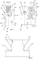
- An example of such a mechanism is depicted in figures 10 and 11 .
- These mechanisms allow for the possibility to realize one-way, two-way, double pole and intermediate switch schemes.
- These mechanisms have the width of one module.
- the width of a module corresponds approximately to 22.5 mm.
- Two modules side-by-side can be mounted into a standard frame of a standard electrical appliance.
- the drawback of such a "see-saw” mechanism is that it occupies relatively much space and in particular the volume above the terminals of the switch, which limits the space in particular for other features like lamps, et cetera.
- Another drawback of such a mechanism is that the distance between the terminals (i.e. the length of the switch) increases when shifted down, that is when the switch mechanism is positioned closer to the operating means (i.e. the height of the switch is reduced).
- Switches comprising a so-called "L" mechanism are also known from prior art.
- An example of such a mechanism is depicted in figure 9 .
- This mechanism can be shifted down without needing to separate the terminals furthermore. That is the height of the switch can be reduced without further increasing its length.
- only one-way and two-way schemes can fit into the width of one module, while the double pole and intermediate switches require the width of two modules.
- JP2003 016873 A shows a switch in which a contact member and an operating means are arranged in a linear articulated manner.
- the operating means is spring-loaded, and the contact member is bi-stably pivotable, about its base and against the spring-loading, into a first and a second position.
- This invention has as its object to remedy to these drawbacks by proposing an electrical switch device having reduced dimensions and offering high functionality. It is a further object of the invention to propose an electrical switch device occupying the width of only one module, allowing for the possibility for realizing one-way, two-way, double pole and intermediate switch schemes and allowing for the switch mechanism to be shifted down without further increasing the length of the switch.
- the electrical switch device comprises an electrical contact assembly and operating means configured to pivot around a first axis of rotation.
- the operating means further comprise a rocker and actuating means extending radially with respect to the first axis in a first direction of extension.
- the electrical contact assembly comprises a movable contact element configured to pivot around a second axis of rotation between a first position and a second position and at least a fixed contact element.
- the movable contact element comprises a contact arm extending radially with respect to the second axis in a second direction of extension.
- the contact arm comprises a first contact surface and the fixed contact comprises a second contact surface.
- the first contact surface and the second contact surface are configured to be in mutual contact when the movable contact element is in the first position.
- the actuating means are configured to act on the movable contact element in order to cause the movement of the movable contact element from the first position to the second position and/or from the second position upon manual action by a user on the rocker.
- a center line of the actuating means extending in the first direction is essentially collinear with a line of the contact arm extending in the second direction and intersecting the first contact surface.
- the electrical switch device according to the invention enables to overcome the drawbacks of the "see-saw” and “L” mechanisms while keeping their advantages.
- the electrical switch device according to the invention allows for the possibility to make all of the above mentioned schemes, that is a one-way, two-way, double pole and intermediate switch schemes within the space of one module,
- the electrical switch device according to the invention further allows for an easy way to provide multipole switch combinations and allows to integrate features like switch lamps et cetera.
- the movable contact element comprises a contact edge extending in parallel to the second axis of rotation, the actuating means being configured to be in physical contact with the contact edge throughout a pivoting motion of the movable contact element between the first position and the second position and/or between the second position and the first position.
- the contact edge may form a third axis of rotation between the movable contact element and the actuating means.
- the actuating means may pivot relative to the movable contact element around the third axis of rotation during a switch operation induced by a manual operation of the operating means by a user.
- the actuating means comprise guiding means and an actuator arranged within the guiding means, the actuator being movable relative to the guiding means in a direction extending radially from the first axis of rotation, in order to stay in physical contact with the contact edge throughout the pivoting motion of the movable contact element between the first position and the second position and/or between the second position and the first position.
- the guiding means comprise two abutment surfaces, the guiding means further being configured to let the actuator swivel freely between the abutment surfaces around the first axis of rotation.
- This embodiment allows for a smooth and continuous motion of the movable contact element and the operating means during the switch operation.
- the actuating means further comprise a spring element physically connected to the guiding means on the one hand and to the actuator on the other hand, the spring element continuously applying a spring force on the actuator throughout the pivoting motion of the movable contact element between the first position and the second position and/or between the second position and the first position.
- This embodiment enables the actuator to remain in contact with the movable contact element throughout the pivoting motion of the movable contact element and therefore allows for a smooth and continuous motion of the movable contact element and the operating means during the switch operation.
- the actuator comprises two actuating arms and an aperture arranged there between, the aperture being configured to receive the contact arm in the middle position of the movable contact element.
- This embodiment allows for the width of the operating means, and in particular the width of the actuator of the operating means, and the width of the contact arm to be reduced.
- the actuator has the general shape of a tuning fork, the actuating arms each essentially extending in a plane perpendicular to the first axis of rotation.
- the guiding means further comprise two gliding surfaces each extending in a plane perpendicular to the first axis of rotation an each being in contact with one of the actuating arms.
- This embodiment allows for a smooth and continuous motion of the movable contact element and the operating means during the switch operation.
- each of the actuating arms comprises a v-shaped actuating portion configured to stay in physical contact with the contact edge throughout the pivoting motion of the movable contact element between the first position and the second position and/or between the second position and the first position.
- This embodiment allows for a smooth and continuous motion of the movable contact element and the operating means during the switch operation.
- the contact arm comprises two embossments on each side of the contact arm, each configured to be in contact with one of the actuating arms in order to center the contact arm between the actuating arms.
- This embodiment allows the contact arm of the movable contact element to be guided during the continuous motion of the movable contact element during the switch operation.
- actuator is made of metal.
- the application relates to an electrical switch device 20.
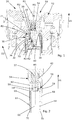
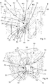
- a preferred embodiment of the electrical switch device 20 is shown in figures 1 to 8 .
- a switch 20" known from prior art and comprising a so-called “see-saw” mechanism 30" is depicted in figures 10 and 11 .
- the switch 20" further comprises operating means 50" for manual operation by a user.
- These mechanisms 30" have a movable contact element 32" and allow for the possibility to realize one-way, two-way, double pole and intermediate switch schemes.
- These mechanisms 30" have the width of one module.
- the width of a module corresponds approximately to 22.5 mm. Two modules side-by-side can be mounted into of standard frame of a standard electrical appliance.
- FIG. 9 Another switch 20' known from prior art and comprising a so-called "L" mechanism 30' is depicted in figure 9 .
- the mechanism comprises a movable contact element 32' and the switch 20' further comprises operating means 50'.
- the movable contact element 32' comprises a contact arm 36' bearing a contact surface 38'.
- the contact arm 36' extends along a primary direction D1'.
- Actuating means 54' of operating means 50' extend along a secondary direction D2'.
- a center line M1' of the actuating means 54' extends parallel to the primary direction D1' and in a plane, which is parallel and distant to a plane in which a line M2' extending parallel to the secondary direction D2' and intersecting the contact surface 38' lies.
- This so-called "L" mechanism 30' can be shifted down without needing to separate the terminals furthermore. That is the height H of the switch 20' can be reduced without further increasing its length L.
- those mechanisms 30' only one-way and two-way schemes can fit into the width of one module, while the double pole and intermediate switches require the width of two modules.
- the electrical switch device 20 comprises an electrical contact assembly 30 and an operating means 50.
- the operating means 50 is configured to pivot around a first axis of rotation R1 and comprises a rocker 52 and actuating means 54 extending radially from the first axis of rotation R1 in a first direction of extension D1.
- the electrical contact assembly 30 comprises a movable contact element 32 configured to pivot around a second axis of rotation R2 between a first position P1 and a second position P2 and at least a fixed contact element 34.
- the movable contact element 32 comprises a contact arm 36 extending radially from the second axis of rotation R2 in a second direction of extension D2.
- the contact arm 36 comprises a first contact surface 38 and the fixed contact 34 comprises a second contact surface 40.
- the first contact surface 38 and the second contact surface 40 are configured to be in mutual contact when the movable contact element 32 is in the first position P1.
- the movable contact element 32 taking the first position P1 is shown in figure 5 .
- the actuating means 54 are configured to act on the movable contact element 32 in order to cause the movement of the movable contact element 32 from the first position P1 to the second position P2 and/or from the second position P2 to the first position P1 upon manual action by a user on the rocker 52.
- the movable contact element 32 taking the second position P2 is shown in figure 1 .
- a center line M1 of the actuating means 54 extending in the first direction D1 is essentially collinear with a line M2 of the contact arm 36 extending in the second direction D2 and intersecting the first contact surface 38.
- the line M2 can also be a center line of the contact arm 36.
- the movable contact element 32 in particular the contact arm 34 of the movable contact element 32, and the actuating means 54 can be configured to pivot in the same plane, that is, that throughout the entire pivoting motion of the movable contact element 32 and the actuating means 54, the center line M1 of the actuating means 54 and the line M2 lie in a sane plane.
- the movable contact element 32 of the electrical switch device 20 comprises a contact edge 42 extending in parallel to the second axis of rotation R2, the actuating means 54 being configured to be in physical contact with the contact edge 42 throughout the pivoting motion of the movable contact element 32 between the first position P1 and the second position P2 and/or between the second position P2 and the first position P1.
- the contact edge 42 forms third axis of rotation R3 between the movable contact element 32 and the actuating means 54.
- the actuating means 54 pivots relative to the movable contact element 32 around the third axis of rotation R3 during a switch operation induced by a manual operation of the operating means 50 by a user.
- the first axis of rotation R1 and/or the second axis of rotation R2 and/or the third axis of rotation R3 may be parallel to each other. In the middle position PM, the first axis of rotation R1 and/or the second axis of rotation R2 and/or the third axis of rotation R3 may all lie in the same plane.
- the contact edge 42 forms a physical fulcrum for the pivoting motion around the third axis of rotation R3 to avoid an unpredictable movement, in particular in the middle position PM, of the actuating means 54 relative to the movable contact 32.
- the actuating means 54 comprise a guiding means 56 and an actuator 58 arranged within the guiding means 56, the actuator 58 being movable relative to the guiding means 56 in a direction extending radially from the first axis of rotation R1, in order to stay in physical contact with the contact edge 42 throughout the pivoting motion of the movable contact element 32 between the first position P1 and the second position P2 and/or between the second position P2 and the first position P1.
- the guiding means 56 are configured to guide the actuator 58.
- the guiding means 56 may comprise two abutment surfaces 60, the guiding means 56 further being configured to let the actuator 58 swivel freely between the abutment surfaces 60 around the first axis of rotation R1.
- the two abutment surfaces 60 may further be configured to be in physical contact with the actuator 58 in either the first position P1 or the second position P2.
- the actuator 58 may comprise one or several cams being in physical contact with one of the abutment surfaces 60 in either the first position P1 or the second position P2.
- the two abutment surfaces 60 may, in vicinity of the contact edge 42, be spaced further apart than in the vicinity of the rocker 52.
- the actuating means 54 may further comprise a spring element 62 physically connected to the guiding means 56 on the one hand and to the actuator 58 on the other hand, the spring element 62 continuously applying a spring force on the actuator 58 throughout the pivoting motion of the movable contact element 32 between the first position P1 and the second position P2 and/or between the second position P2 and the first position P1.
- the guiding means 56 may comprise a retention peg 57 connected to the spring element 62.
- the actuator 58 may comprise spring clips 59 for connecting the actuator 58 to the spring element 62.
- the spring clips 59 and/or the retention peg 57 may be so designed to act only on the extremity of the spring element 62, in order not to impair to the spring force of the spring element 62.
- the retention peg 57 and the spring clips 59 safely hold the spring element 62 and the actuator 58 in place in a single subassembly with the operating means 50.
- the single subassembly can be safely manipulated during the assembly of the electrical switch device 20, limiting the loss of internal parts.
- the actuator 58 comprises two actuating arms 64 and an aperture 66 arranged there between, the aperture 66 being configured to receive the contact arm 36 in the middle position PM of the movable contact element 32.
- the contact arm 36 rotates through the aperture 66 when moving from the first position P1 to the second position P2 and/or from the second position P2 to the first position P1.
- the first contact surface 38 may be arranged between the two actuating arms 64 within the aperture 66 in the middle position PM.
- the actuator 58 may have the general shape of a tuning fork, the actuating arms 64 each essentially extending in a plane perpendicular to the first axis of rotation R1.
- the guiding means 56 may further comprise two gliding surfaces 68 each extending in a plane perpendicular to the first axis of rotation R1 and each being in contact with one of the actuating arms 64.
- Each of the actuating arms 64 may comprise a v-shaped actuating portion 70 configured to stay in physical contact with the contact edge 42 throughout the pivoting motion of the movable contact element 32 between the first position P1 and the second position P2 and/or between the second position P2 and the first position P1.
- the physical fulcrum may be formed between the actuating portion 70 and the contact edge 42.
- the v-shaped actuating portion 70 also facilitates catching of the contact edge 42 of the movable contact 32 during the assembling operation of the electrical switch device 20.
- the contact arm 36 comprises two embossments 44 on each side of the contact arm 36, each configured to be in contact with one of the actuating arms 64 in order to center the contact arm 36 between the actuating arms 64.
- This embodiment facilitates the rotational movement of the contact arm 34 through the aperture 66.
- the two embossments 44 can ensure that a space of at least 0.5 mm is kept between the actuating arms 64 and the end of the contact arm 36.
- the two embossments 44 are positioned close to the contact edge 42. This preferred embodiment allows to limit the friction between the embossments 44 and actuating arm 64 during the rotational movement of the movable contact element 32.
- the actuator 58 and/or the spring element 62 and/or the electrical contact assembly 30 may be made of metal.
- An actuator 58 made of metal can reduce the undesirable consumption and deformation of the actuator 58 due to the applied force, friction and eating effect under load conditions.
- Figures 1 and 3 to 5 illustrate the movement of the movable contact element 32 from the second position P2 to the first position P1.
- the end of the contact arm 36 rests against an inner wall 21 of the electrical switch device 20.
- the inner wall 21 may extend parallel to the first direction of extension D1 when the movable contact element 32 takes the second position P2.
- the actuating means 54 in particular the actuator 58 and/or the actuating portion 70, act(s) upon the movable contact 32 and in particular on the contact edge 42 of the movable contact 32 by means of a spring force induced by the spring element 62, in order to maintain the end of the contact arm 36 to rest against the inner wall 21.
- the movable contact element 32 may leave the second position P2, such that the end of the contact arm 36 is removed from the wall 21.
- the movable contact element 32 may reach the middle position PM.
- the middle position PM is depicted in figure 3 . Due to the spring force induced by the spring element 62 and applied to the movable contact element 32 via the actuating means 54 and in particular the actuator 58 of the actuating means 54, the operating means 50 and the movable contact element 32 are in an unstable equilibrium.
- the center line M1 and the line M2 are collinear.
- the first axis of rotation R1, the second axis of rotation R2 and the third axis of rotation R3 extend in the same plane.
- the operating means 50 and the movable contact element 32 leave the stable equilibrium and the contact arm 36 of the movable contact element 32 and/or the first contact surface 38 move(s) towards the fixed contact element 34 and/or the second contact surface 40.
- the spring force induced by the spring element 62 urges the movable contact element 32 towards the first position P1 without the need of further manual action by the user on the rocker 52.
- the first contact surface 38 is in contact with the second contact surface 40.
- the movable contact element 32 taking the first position P1 is shown in figure 5 .
Landscapes
- Rotary Switch, Piano Key Switch, And Lever Switch (AREA)
Claims (7)
- Dispositif de commutateur électrique comportant un ensemble (30) de contacts électriques et des moyens (50) de manœuvre,
les moyens (50) de manœuvre étant configurés pour pivoter autour d'un premier axe de rotation (R1) et comportant un basculeur (52) et des moyens (54) d'actionnement s'étendant radialement à partir du premier axe de rotation (R1) dans une première direction d'extension (D1),
l'ensemble (30) de contacts électriques comportant un élément (32) de contact mobile configuré pour pivoter autour d'un second axe de rotation (R2) entre une première position (P1) et une seconde position (P2) et au moins un élément (34) de contact fixe,
l'élément (32) de contact mobile comportant un bras (36) de contact s'étendant radialement à partir du second axe de rotation (R2) dans une seconde direction d'extension (D2),
le bras (36) de contact comportant une première surface (38) de contact et le contact fixe (34) comportant une seconde surface (40) de contact,
la première surface (38) de contact et la seconde surface (40) de contact étant configurées pour être en contact mutuel lorsque l'élément (32) de contact mobile est dans la première position (P1),
l'élément (32) de contact mobile comportant une arête (42) de contact s'étendant parallèlement au second axe de rotation (R2),
les moyens (54) d'actionnement étant configurés pour agir sur l'élément (32) de contact mobile afin de provoquer le déplacement de l'élément (32) de contact mobile de la première position (P1) à la seconde position (P2) et/ou de la seconde position (P2) à la première position (P1) suite à une action manuelle par un utilisateur sur le basculeur (52),
les moyens (54) d'actionnement comportant des moyens (56) de guidage et un actionneur (58) agencé à l'intérieur des moyens (56) de guidage, l'actionneur (58) pouvant être déplacé par rapport aux moyens (56) de guidage dans une direction s'étendant radialement à partir du premier axe de rotation (R1), afin de rester en contact physique avec l'arête (42) de contact pendant tout le mouvement de pivotement de l'élément (32) de contact mobile entre la première position (P1) et la seconde position (P2) et/ou entre la seconde position (P2) et la première position (P1), l'actionneur (58) comportant deux bras (64) d'actionnement et une ouverture (66) ménagée entre ceux-ci, l'ouverture (66) étant configurée pour recevoir le bras (36) de contact dans la position médiane (PM) de l'élément (32) de contact mobile, dans une position médiane (PM) de l'élément (32) de contact mobile placée entre la première position (P1) et la seconde position (P2), une ligne centrale (M1) des moyens (54) d'actionnement s'étendant dans la première direction (D1) étant essentiellement colinéaire avec une ligne (M2) du bras (36) de contact s'étendant dans la seconde direction (D2),
caractérisé en ce que le bras (36) de contact comporte deux bossages (44) de chaque côté du bras (36) de contact, chacun configuré pour être en contact avec un des bras (64) d'actionnement afin de centrer le bras (36) de contact entre les bras (64) d'actionnement. - Dispositif de commutateur électrique selon la revendication 1, caractérisé en ce que les moyens (56) de guidage comportent deux surfaces (60) d'appui, les moyens (56) de guidage étant en outre configurés pour laisser l'actionneur (58) osciller librement entre les surfaces (60) d'appui autour du premier axe de rotation (R1) .
- Dispositif de commutateur électrique selon l'une quelconque des revendications 1 et 2, caractérisé en ce que les moyens (54) d'actionnement comportent en outre un élément (62) de ressort lié physiquement d'une part aux moyens (56) de guidage et d'autre part à l'actionneur (58), l'élément (62) de ressort appliquant continûment une force élastique sur l'actionneur (58) pendant tout le mouvement de pivotement de l'élément (32) de contact mobile entre la première position (P1) et la seconde position (P2) et/ou entre la seconde position (P2) et la première position (P1).
- Dispositif de commutateur électrique selon l'une quelconque des revendications précédentes, caractérisé en ce que l'actionneur (58) présente la forme générale d'un diapason, chacun des bras (64) d'actionnement s'étendant essentiellement dans un plan perpendiculaire au premier axe de rotation (R1).
- Dispositif de commutateur électrique selon la revendication 4, caractérisé en ce que les moyens (56) de guidage comportent en outre deux surfaces (68) de glissement s'étendant chacune dans un plan perpendiculaire au premier axe de rotation (R1) et étant chacune en contact avec un des bras (64) d'actionnement.
- Dispositif de commutateur électrique selon l'une quelconque des revendications précédentes, caractérisé en ce que chacun des bras (64) d'actionnement comporte une partie (70) d'actionnement en V configurée pour rester en contact physique avec l'arête (42) de contact pendant tout le mouvement de pivotement de l'élément (32) de contact mobile entre la première position (P1) et la seconde position (P2) et/ou entre la seconde position (P2) et la première position (P1).
- Dispositif de commutateur électrique selon l'une quelconque des revendications précédentes, caractérisé en ce que l'actionneur (58) est constitué de métal.
Priority Applications (1)
| Application Number | Priority Date | Filing Date | Title |
|---|---|---|---|
| EP18305740.5A EP3582242B1 (fr) | 2018-06-15 | 2018-06-15 | Dispositif de commutation électrique |
Applications Claiming Priority (1)
| Application Number | Priority Date | Filing Date | Title |
|---|---|---|---|
| EP18305740.5A EP3582242B1 (fr) | 2018-06-15 | 2018-06-15 | Dispositif de commutation électrique |
Publications (2)
| Publication Number | Publication Date |
|---|---|
| EP3582242A1 EP3582242A1 (fr) | 2019-12-18 |
| EP3582242B1 true EP3582242B1 (fr) | 2021-01-27 |
Family
ID=62778855
Family Applications (1)
| Application Number | Title | Priority Date | Filing Date |
|---|---|---|---|
| EP18305740.5A Active EP3582242B1 (fr) | 2018-06-15 | 2018-06-15 | Dispositif de commutation électrique |
Country Status (1)
| Country | Link |
|---|---|
| EP (1) | EP3582242B1 (fr) |
Families Citing this family (1)
| Publication number | Priority date | Publication date | Assignee | Title |
|---|---|---|---|---|
| CN112927973B (zh) * | 2021-01-29 | 2023-01-10 | 中山市狮盾电气有限公司 | 一种触片的摆动结构及其面板开关 |
Family Cites Families (1)
| Publication number | Priority date | Publication date | Assignee | Title |
|---|---|---|---|---|
| JP4553088B2 (ja) * | 2001-06-29 | 2010-09-29 | 東芝ライテック株式会社 | スイッチ装置 |
-
2018
- 2018-06-15 EP EP18305740.5A patent/EP3582242B1/fr active Active
Non-Patent Citations (1)
| Title |
|---|
| None * |
Also Published As
| Publication number | Publication date |
|---|---|
| EP3582242A1 (fr) | 2019-12-18 |
Similar Documents
| Publication | Publication Date | Title |
|---|---|---|
| US9978537B2 (en) | Contact bridge arrangement for an electrical switching element | |
| JP5618396B2 (ja) | リレー | |
| US3997745A (en) | Switches | |
| US20030016115A1 (en) | Safety press-button switch | |
| RU2444079C2 (ru) | Механизм с двумя фиксированными положениями и электричекое устройство управления, содержащее этот механизм | |
| JP2023066400A (ja) | 電気スイッチング素子のためのスイッチングコンタクトアセンブリおよび電気スイッチング素子 | |
| US2295484A (en) | Push-push operating mechanism for electric switches | |
| CN102687219B (zh) | 旋转的双触点 | |
| US4543459A (en) | Small-sized switch | |
| EP3582242A1 (fr) | Dispositif de commutation électrique | |
| US6504116B2 (en) | Switch | |
| JP4173006B2 (ja) | 開閉接触子装置 | |
| ES2328255T3 (es) | Interructor electrico. | |
| JP4184001B2 (ja) | 切換継電器 | |
| US2525044A (en) | Snap action switch | |
| US3256413A (en) | Wafer thin thermostat | |
| EP3051562B1 (fr) | Élément ressort pour un dispositif de commutation électrique, tel qu'un relais à berceau | |
| KR20080109822A (ko) | 스위블링 레버 스위치 메커니즘을 구비한 전기 스위치 소자, 특히 릴레이 | |
| EP3570302B1 (fr) | Ensemble étrier pour un dispositif de commutation magnétique, tel qu'un relais, ensemble magnétique et dispositif de commutation magnétique | |
| US1878667A (en) | Mercury switch | |
| US7935905B2 (en) | Contact system | |
| US6797904B1 (en) | Microswitch | |
| US2773145A (en) | Snap action switch | |
| US5525952A (en) | Switchblade | |
| US2095179A (en) | Push button electric switch |
Legal Events
| Date | Code | Title | Description |
|---|---|---|---|
| PUAI | Public reference made under article 153(3) epc to a published international application that has entered the european phase |
Free format text: ORIGINAL CODE: 0009012 |
|
| STAA | Information on the status of an ep patent application or granted ep patent |
Free format text: STATUS: THE APPLICATION HAS BEEN PUBLISHED |
|
| AK | Designated contracting states |
Kind code of ref document: A1 Designated state(s): AL AT BE BG CH CY CZ DE DK EE ES FI FR GB GR HR HU IE IS IT LI LT LU LV MC MK MT NL NO PL PT RO RS SE SI SK SM TR |
|
| AX | Request for extension of the european patent |
Extension state: BA ME |
|
| STAA | Information on the status of an ep patent application or granted ep patent |
Free format text: STATUS: REQUEST FOR EXAMINATION WAS MADE |
|
| 17P | Request for examination filed |
Effective date: 20200615 |
|
| RBV | Designated contracting states (corrected) |
Designated state(s): AL AT BE BG CH CY CZ DE DK EE ES FI FR GB GR HR HU IE IS IT LI LT LU LV MC MK MT NL NO PL PT RO RS SE SI SK SM TR |
|
| RIC1 | Information provided on ipc code assigned before grant |
Ipc: H01H 23/20 20060101AFI20200624BHEP |
|
| GRAP | Despatch of communication of intention to grant a patent |
Free format text: ORIGINAL CODE: EPIDOSNIGR1 |
|
| STAA | Information on the status of an ep patent application or granted ep patent |
Free format text: STATUS: GRANT OF PATENT IS INTENDED |
|
| INTG | Intention to grant announced |
Effective date: 20200821 |
|
| GRAS | Grant fee paid |
Free format text: ORIGINAL CODE: EPIDOSNIGR3 |
|
| GRAA | (expected) grant |
Free format text: ORIGINAL CODE: 0009210 |
|
| STAA | Information on the status of an ep patent application or granted ep patent |
Free format text: STATUS: THE PATENT HAS BEEN GRANTED |
|
| AK | Designated contracting states |
Kind code of ref document: B1 Designated state(s): AL AT BE BG CH CY CZ DE DK EE ES FI FR GB GR HR HU IE IS IT LI LT LU LV MC MK MT NL NO PL PT RO RS SE SI SK SM TR |
|
| REG | Reference to a national code |
Ref country code: GB Ref legal event code: FG4D |
|
| REG | Reference to a national code |
Ref country code: CH Ref legal event code: EP |
|
| REG | Reference to a national code |
Ref country code: AT Ref legal event code: REF Ref document number: 1359108 Country of ref document: AT Kind code of ref document: T Effective date: 20210215 |
|
| REG | Reference to a national code |
Ref country code: IE Ref legal event code: FG4D |
|
| REG | Reference to a national code |
Ref country code: DE Ref legal event code: R096 Ref document number: 602018012290 Country of ref document: DE |
|
| REG | Reference to a national code |
Ref country code: NL Ref legal event code: MP Effective date: 20210127 |
|
| REG | Reference to a national code |
Ref country code: LT Ref legal event code: MG9D |
|
| REG | Reference to a national code |
Ref country code: AT Ref legal event code: MK05 Ref document number: 1359108 Country of ref document: AT Kind code of ref document: T Effective date: 20210127 |
|
| PG25 | Lapsed in a contracting state [announced via postgrant information from national office to epo] |
Ref country code: PT Free format text: LAPSE BECAUSE OF FAILURE TO SUBMIT A TRANSLATION OF THE DESCRIPTION OR TO PAY THE FEE WITHIN THE PRESCRIBED TIME-LIMIT Effective date: 20210527 Ref country code: NO Free format text: LAPSE BECAUSE OF FAILURE TO SUBMIT A TRANSLATION OF THE DESCRIPTION OR TO PAY THE FEE WITHIN THE PRESCRIBED TIME-LIMIT Effective date: 20210427 Ref country code: LT Free format text: LAPSE BECAUSE OF FAILURE TO SUBMIT A TRANSLATION OF THE DESCRIPTION OR TO PAY THE FEE WITHIN THE PRESCRIBED TIME-LIMIT Effective date: 20210127 Ref country code: HR Free format text: LAPSE BECAUSE OF FAILURE TO SUBMIT A TRANSLATION OF THE DESCRIPTION OR TO PAY THE FEE WITHIN THE PRESCRIBED TIME-LIMIT Effective date: 20210127 Ref country code: GR Free format text: LAPSE BECAUSE OF FAILURE TO SUBMIT A TRANSLATION OF THE DESCRIPTION OR TO PAY THE FEE WITHIN THE PRESCRIBED TIME-LIMIT Effective date: 20210428 Ref country code: FI Free format text: LAPSE BECAUSE OF FAILURE TO SUBMIT A TRANSLATION OF THE DESCRIPTION OR TO PAY THE FEE WITHIN THE PRESCRIBED TIME-LIMIT Effective date: 20210127 Ref country code: BG Free format text: LAPSE BECAUSE OF FAILURE TO SUBMIT A TRANSLATION OF THE DESCRIPTION OR TO PAY THE FEE WITHIN THE PRESCRIBED TIME-LIMIT Effective date: 20210427 |
|
| PG25 | Lapsed in a contracting state [announced via postgrant information from national office to epo] |
Ref country code: AT Free format text: LAPSE BECAUSE OF FAILURE TO SUBMIT A TRANSLATION OF THE DESCRIPTION OR TO PAY THE FEE WITHIN THE PRESCRIBED TIME-LIMIT Effective date: 20210127 Ref country code: LV Free format text: LAPSE BECAUSE OF FAILURE TO SUBMIT A TRANSLATION OF THE DESCRIPTION OR TO PAY THE FEE WITHIN THE PRESCRIBED TIME-LIMIT Effective date: 20210127 Ref country code: RS Free format text: LAPSE BECAUSE OF FAILURE TO SUBMIT A TRANSLATION OF THE DESCRIPTION OR TO PAY THE FEE WITHIN THE PRESCRIBED TIME-LIMIT Effective date: 20210127 Ref country code: PL Free format text: LAPSE BECAUSE OF FAILURE TO SUBMIT A TRANSLATION OF THE DESCRIPTION OR TO PAY THE FEE WITHIN THE PRESCRIBED TIME-LIMIT Effective date: 20210127 Ref country code: SE Free format text: LAPSE BECAUSE OF FAILURE TO SUBMIT A TRANSLATION OF THE DESCRIPTION OR TO PAY THE FEE WITHIN THE PRESCRIBED TIME-LIMIT Effective date: 20210127 |
|
| PG25 | Lapsed in a contracting state [announced via postgrant information from national office to epo] |
Ref country code: IS Free format text: LAPSE BECAUSE OF FAILURE TO SUBMIT A TRANSLATION OF THE DESCRIPTION OR TO PAY THE FEE WITHIN THE PRESCRIBED TIME-LIMIT Effective date: 20210527 |
|
| REG | Reference to a national code |
Ref country code: DE Ref legal event code: R097 Ref document number: 602018012290 Country of ref document: DE |
|
| PG25 | Lapsed in a contracting state [announced via postgrant information from national office to epo] |
Ref country code: EE Free format text: LAPSE BECAUSE OF FAILURE TO SUBMIT A TRANSLATION OF THE DESCRIPTION OR TO PAY THE FEE WITHIN THE PRESCRIBED TIME-LIMIT Effective date: 20210127 Ref country code: CZ Free format text: LAPSE BECAUSE OF FAILURE TO SUBMIT A TRANSLATION OF THE DESCRIPTION OR TO PAY THE FEE WITHIN THE PRESCRIBED TIME-LIMIT Effective date: 20210127 Ref country code: SM Free format text: LAPSE BECAUSE OF FAILURE TO SUBMIT A TRANSLATION OF THE DESCRIPTION OR TO PAY THE FEE WITHIN THE PRESCRIBED TIME-LIMIT Effective date: 20210127 |
|
| PG25 | Lapsed in a contracting state [announced via postgrant information from national office to epo] |
Ref country code: DK Free format text: LAPSE BECAUSE OF FAILURE TO SUBMIT A TRANSLATION OF THE DESCRIPTION OR TO PAY THE FEE WITHIN THE PRESCRIBED TIME-LIMIT Effective date: 20210127 Ref country code: RO Free format text: LAPSE BECAUSE OF FAILURE TO SUBMIT A TRANSLATION OF THE DESCRIPTION OR TO PAY THE FEE WITHIN THE PRESCRIBED TIME-LIMIT Effective date: 20210127 Ref country code: SK Free format text: LAPSE BECAUSE OF FAILURE TO SUBMIT A TRANSLATION OF THE DESCRIPTION OR TO PAY THE FEE WITHIN THE PRESCRIBED TIME-LIMIT Effective date: 20210127 |
|
| PLBE | No opposition filed within time limit |
Free format text: ORIGINAL CODE: 0009261 |
|
| STAA | Information on the status of an ep patent application or granted ep patent |
Free format text: STATUS: NO OPPOSITION FILED WITHIN TIME LIMIT |
|
| 26N | No opposition filed |
Effective date: 20211028 |
|
| PG25 | Lapsed in a contracting state [announced via postgrant information from national office to epo] |
Ref country code: ES Free format text: LAPSE BECAUSE OF FAILURE TO SUBMIT A TRANSLATION OF THE DESCRIPTION OR TO PAY THE FEE WITHIN THE PRESCRIBED TIME-LIMIT Effective date: 20210127 Ref country code: AL Free format text: LAPSE BECAUSE OF FAILURE TO SUBMIT A TRANSLATION OF THE DESCRIPTION OR TO PAY THE FEE WITHIN THE PRESCRIBED TIME-LIMIT Effective date: 20210127 Ref country code: MC Free format text: LAPSE BECAUSE OF FAILURE TO SUBMIT A TRANSLATION OF THE DESCRIPTION OR TO PAY THE FEE WITHIN THE PRESCRIBED TIME-LIMIT Effective date: 20210127 |
|
| REG | Reference to a national code |
Ref country code: CH Ref legal event code: PL |
|
| PG25 | Lapsed in a contracting state [announced via postgrant information from national office to epo] |
Ref country code: SI Free format text: LAPSE BECAUSE OF FAILURE TO SUBMIT A TRANSLATION OF THE DESCRIPTION OR TO PAY THE FEE WITHIN THE PRESCRIBED TIME-LIMIT Effective date: 20210127 |
|
| PG25 | Lapsed in a contracting state [announced via postgrant information from national office to epo] |
Ref country code: LU Free format text: LAPSE BECAUSE OF NON-PAYMENT OF DUE FEES Effective date: 20210615 |
|
| PG25 | Lapsed in a contracting state [announced via postgrant information from national office to epo] |
Ref country code: LI Free format text: LAPSE BECAUSE OF NON-PAYMENT OF DUE FEES Effective date: 20210630 Ref country code: IE Free format text: LAPSE BECAUSE OF NON-PAYMENT OF DUE FEES Effective date: 20210615 Ref country code: CH Free format text: LAPSE BECAUSE OF NON-PAYMENT OF DUE FEES Effective date: 20210630 |
|
| PG25 | Lapsed in a contracting state [announced via postgrant information from national office to epo] |
Ref country code: IS Free format text: LAPSE BECAUSE OF FAILURE TO SUBMIT A TRANSLATION OF THE DESCRIPTION OR TO PAY THE FEE WITHIN THE PRESCRIBED TIME-LIMIT Effective date: 20210527 |
|
| GBPC | Gb: european patent ceased through non-payment of renewal fee |
Effective date: 20220615 |
|
| PG25 | Lapsed in a contracting state [announced via postgrant information from national office to epo] |
Ref country code: GB Free format text: LAPSE BECAUSE OF NON-PAYMENT OF DUE FEES Effective date: 20220615 |
|
| PG25 | Lapsed in a contracting state [announced via postgrant information from national office to epo] |
Ref country code: NL Free format text: LAPSE BECAUSE OF NON-PAYMENT OF DUE FEES Effective date: 20210127 Ref country code: CY Free format text: LAPSE BECAUSE OF FAILURE TO SUBMIT A TRANSLATION OF THE DESCRIPTION OR TO PAY THE FEE WITHIN THE PRESCRIBED TIME-LIMIT Effective date: 20210127 |
|
| P01 | Opt-out of the competence of the unified patent court (upc) registered |
Effective date: 20230606 |
|
| PG25 | Lapsed in a contracting state [announced via postgrant information from national office to epo] |
Ref country code: HU Free format text: LAPSE BECAUSE OF FAILURE TO SUBMIT A TRANSLATION OF THE DESCRIPTION OR TO PAY THE FEE WITHIN THE PRESCRIBED TIME-LIMIT; INVALID AB INITIO Effective date: 20180615 |
|
| PG25 | Lapsed in a contracting state [announced via postgrant information from national office to epo] |
Ref country code: MK Free format text: LAPSE BECAUSE OF FAILURE TO SUBMIT A TRANSLATION OF THE DESCRIPTION OR TO PAY THE FEE WITHIN THE PRESCRIBED TIME-LIMIT Effective date: 20210127 |
|
| PG25 | Lapsed in a contracting state [announced via postgrant information from national office to epo] |
Ref country code: TR Free format text: LAPSE BECAUSE OF FAILURE TO SUBMIT A TRANSLATION OF THE DESCRIPTION OR TO PAY THE FEE WITHIN THE PRESCRIBED TIME-LIMIT Effective date: 20210127 |
|
| PG25 | Lapsed in a contracting state [announced via postgrant information from national office to epo] |
Ref country code: MT Free format text: LAPSE BECAUSE OF FAILURE TO SUBMIT A TRANSLATION OF THE DESCRIPTION OR TO PAY THE FEE WITHIN THE PRESCRIBED TIME-LIMIT Effective date: 20210127 |
|
| PGFP | Annual fee paid to national office [announced via postgrant information from national office to epo] |
Ref country code: IT Payment date: 20260622 Year of fee payment: 9 |
|
| PGFP | Annual fee paid to national office [announced via postgrant information from national office to epo] |
Ref country code: DE Payment date: 20260629 Year of fee payment: 9 |
|
| PGFP | Annual fee paid to national office [announced via postgrant information from national office to epo] |
Ref country code: BE Payment date: 20260629 Year of fee payment: 9 |
|
| PGFP | Annual fee paid to national office [announced via postgrant information from national office to epo] |
Ref country code: FR Payment date: 20260625 Year of fee payment: 9 |