EP3582490B1 - Appareil de fusion d'image et procédé de fusion d'image - Google Patents
Appareil de fusion d'image et procédé de fusion d'image Download PDFInfo
- Publication number
- EP3582490B1 EP3582490B1 EP18750832.0A EP18750832A EP3582490B1 EP 3582490 B1 EP3582490 B1 EP 3582490B1 EP 18750832 A EP18750832 A EP 18750832A EP 3582490 B1 EP3582490 B1 EP 3582490B1
- Authority
- EP
- European Patent Office
- Prior art keywords
- channel
- value
- image
- signal
- channels
- Prior art date
- Legal status (The legal status is an assumption and is not a legal conclusion. Google has not performed a legal analysis and makes no representation as to the accuracy of the status listed.)
- Active
Links
Images




Classifications
-
- G—PHYSICS
- G06—COMPUTING OR CALCULATING; COUNTING
- G06T—IMAGE DATA PROCESSING OR GENERATION, IN GENERAL
- G06T3/00—Geometric image transformations in the plane of the image
- G06T3/40—Scaling of whole images or parts thereof, e.g. expanding or contracting
- G06T3/4015—Image demosaicing, e.g. colour filter arrays [CFA] or Bayer patterns
-
- G—PHYSICS
- G06—COMPUTING OR CALCULATING; COUNTING
- G06T—IMAGE DATA PROCESSING OR GENERATION, IN GENERAL
- G06T5/00—Image enhancement or restoration
- G06T5/50—Image enhancement or restoration using two or more images, e.g. averaging or subtraction
-
- H—ELECTRICITY
- H04—ELECTRIC COMMUNICATION TECHNIQUE
- H04N—PICTORIAL COMMUNICATION, e.g. TELEVISION
- H04N23/00—Cameras or camera modules comprising electronic image sensors; Control thereof
- H04N23/10—Cameras or camera modules comprising electronic image sensors; Control thereof for generating image signals from different wavelengths
- H04N23/11—Cameras or camera modules comprising electronic image sensors; Control thereof for generating image signals from different wavelengths for generating image signals from visible and infrared light wavelengths
-
- H—ELECTRICITY
- H04—ELECTRIC COMMUNICATION TECHNIQUE
- H04N—PICTORIAL COMMUNICATION, e.g. TELEVISION
- H04N23/00—Cameras or camera modules comprising electronic image sensors; Control thereof
- H04N23/20—Cameras or camera modules comprising electronic image sensors; Control thereof for generating image signals from infrared radiation only
-
- H—ELECTRICITY
- H04—ELECTRIC COMMUNICATION TECHNIQUE
- H04N—PICTORIAL COMMUNICATION, e.g. TELEVISION
- H04N23/00—Cameras or camera modules comprising electronic image sensors; Control thereof
- H04N23/45—Cameras or camera modules comprising electronic image sensors; Control thereof for generating image signals from two or more image sensors being of different type or operating in different modes, e.g. with a CMOS sensor for moving images in combination with a charge-coupled device [CCD] for still images
-
- H—ELECTRICITY
- H04—ELECTRIC COMMUNICATION TECHNIQUE
- H04N—PICTORIAL COMMUNICATION, e.g. TELEVISION
- H04N25/00—Circuitry of solid-state image sensors [SSIS]; Control thereof
- H04N25/10—Circuitry of solid-state image sensors [SSIS]; Control thereof for transforming different wavelengths into image signals
- H04N25/11—Arrangement of colour filter arrays [CFA]; Filter mosaics
- H04N25/13—Arrangement of colour filter arrays [CFA]; Filter mosaics characterised by the spectral characteristics of the filter elements
- H04N25/131—Arrangement of colour filter arrays [CFA]; Filter mosaics characterised by the spectral characteristics of the filter elements including elements passing infrared wavelengths
-
- H—ELECTRICITY
- H04—ELECTRIC COMMUNICATION TECHNIQUE
- H04N—PICTORIAL COMMUNICATION, e.g. TELEVISION
- H04N25/00—Circuitry of solid-state image sensors [SSIS]; Control thereof
- H04N25/10—Circuitry of solid-state image sensors [SSIS]; Control thereof for transforming different wavelengths into image signals
- H04N25/11—Arrangement of colour filter arrays [CFA]; Filter mosaics
- H04N25/13—Arrangement of colour filter arrays [CFA]; Filter mosaics characterised by the spectral characteristics of the filter elements
- H04N25/135—Arrangement of colour filter arrays [CFA]; Filter mosaics characterised by the spectral characteristics of the filter elements based on four or more different wavelength filter elements
-
- H—ELECTRICITY
- H04—ELECTRIC COMMUNICATION TECHNIQUE
- H04N—PICTORIAL COMMUNICATION, e.g. TELEVISION
- H04N25/00—Circuitry of solid-state image sensors [SSIS]; Control thereof
- H04N25/50—Control of the SSIS exposure
- H04N25/53—Control of the integration time
- H04N25/533—Control of the integration time by using differing integration times for different sensor regions
- H04N25/534—Control of the integration time by using differing integration times for different sensor regions depending on the spectral component
-
- G—PHYSICS
- G06—COMPUTING OR CALCULATING; COUNTING
- G06T—IMAGE DATA PROCESSING OR GENERATION, IN GENERAL
- G06T2207/00—Indexing scheme for image analysis or image enhancement
- G06T2207/20—Special algorithmic details
- G06T2207/20212—Image combination
- G06T2207/20221—Image fusion; Image merging
Definitions
- the present application relates to the technical field of image processing, and in particular, to an image fusion apparatus and image fusion method.
- an image acquisition device with a beam splitting and fusion function is usually required to acquire an image, in order to ensure that the acquired image contains more image information.
- the basic principle for acquisition an image through the image acquisition device with the beam splitting and fusion function is as follows: acquiring a visible light image corresponding to visible light signals and acquisition an infrared image corresponding to infrared light signals, and fusing the visible light image and the infrared image to obtain a fused image.
- the fused image is a dual-band image, which contains more image information than a single-band image, either the visible light image or the infrared light image.
- the image acquisition device with the beam splitting and fusion function specifically includes a transflective mirror, a visible light sensor, an infrared light sensor, a registration unit, and a fusion unit.
- the transflective mirror is used to separate incident light into visible light and infrared light.
- the visible light sensor is used to acquire visible light to produce a visible light image
- the infrared light sensor is used to acquire infrared light to produce an infrared image.
- the registration unit is used to eliminate a position deviation between the infrared image and the visible light image.
- the fusion unit is used to perform weighted fusion on the infrared image and the visible light image the positions of which have been corrected by the registration unit.
- the resulting fused image obtained by the fusion is an output image of the image acquisition device.
- the image acquisition device with the beam splitting and fusion function can obtain a fused image.
- an image processor When receiving the visible light image, an image processor will remove the infrared component from the visible light image (i.e., the color signal). This requires a large amount of calculation and thus results in a low efficiency of image fusion.
- the patent application US2016065926A1 discloses an image-capturing device including: a visible light signal generating unit that extracts a visible light signal from a pixel signal from an image-capturing element; a light source color estimating unit that estimates a color temperature of a light source from the visible light signal; a white-balance adjusting unit that performs white balance correction on the visible light signal according to an estimation result; a non-visible light signal generating unit that extracts a non-visible light signal from the signals from the image-capturing element; and an image composing unit that combines and outputs the visible light signal on which the white balance correction was performed and the non-visible light signal.
- the patent application WO2015198127A1 discloses an imaging processing device and an imaging processing method, which can resolve problems occurring in visible light imaging when a double band pass filter (DBPF) is used instead of an infrared cut-off filter.
- An imaging sensor comprises: a color filter, and a DBPF that has transparency characteristics in the visible light spectrum, blocking characteristics in a first wavelength spectrum adjacent to the long wavelength side of the visible light spectrum and transparency characteristics in a second wavelength spectrum which is a part of the first wavelength spectrum.
- a signal processing unit subtracts, from each color signal outputted from each color pixel of visible light in the imaging sensor, an infrared signal outputted from an infrared pixel. When doing so, if a color signal reaches a pixel saturation level, a correction control iis performed to reduce the value of the infrared signal subtracted from each color signal.
- the patent application WO2016027397A1 discloses a solid-state image pickup apparatus, comprising: an image pickup unit that is constituted by a plurality of pixels; a row selection circuit that controls charge storage periods and that selects pixels on a row-by-row basis from the plurality of pixels; and a read circuit that reads signals from the pixels selected by the row selection circuit.
- an image pickup unit that is constituted by a plurality of pixels
- a row selection circuit that controls charge storage periods and that selects pixels on a row-by-row basis from the plurality of pixels
- a read circuit that reads signals from the pixels selected by the row selection circuit.
- Each of the plurality of pixels constituting the image pickup unit is classified as any one of a plurality of types of pixels receiving lights having different properties.
- the row selection circuit controls the charge storage periods such that, for the pixels located in each same row in the image pickup unit, the charge storage period of first type of pixels (G-pixels, R-pixels and B-pixels) among the plurality of types of pixels is a first charge storage period and the charge storage period of second type of pixels (IR-pixels) among the plurality of types of pixels is a second charge storage period.
- the objective of embodiments of the present application is to provide image fusion apparatuses and image fusion methods, to reduce the amount of calculation for removing an infrared component from a color signal by a processor and to improve the efficiency of image fusion.
- the specific technical solutions are as follows.
- an image fusion apparatus including:
- an image fusion apparatus including:
- an embodiment of the present application further provides an image fusion method, which is applicable to an image fusion apparatus.
- the image fusion apparatus has four types of photosensitive channels, which include red, green and blue RGB channels and an infrared IR channel.
- the method includes:
- an embodiment of the present application provides an image fusion method, which is applicable to an image fusion apparatus.
- the image fusion apparatus has four types of photosensitive channels, which include red, green and blue RGB channels and a full band W channel.
- the method includes:
- an embodiment of the present application provides a storage medium for storing executable codes.
- the executable codes are executed to perform steps of the image fusion method provided by the embodiment of the present application in the third aspect.
- an embodiment of the present application provides a storage medium for storing executable codes.
- the executable codes are executed to perform steps of the image fusion method provided by the embodiment of the present application in the fourth aspect.
- an embodiment of the present application provides an application program that, when executed, carries out steps of the image fusion method provided by the embodiment of the present application in the third aspect.
- an embodiment of the present application provides an application program that, when executed, carries out steps of the image fusion method provided by the embodiment of the present application in the fourth aspect.
- the light acquisition device filters the spectrum component of the first predetermined wavelength range from the incident light, so that the portion in which there is a large difference between the quantum efficiencies of the channels at the near-infrared band is filtered out.
- This can simplify the calculations performed by the image processor to remove the infrared component from the color signals, and thus improve the efficiency of the image fusion.
- the image fusion apparatus provided by the embodiment of the present application uses the image sensor having the four types of photosensitive channels to acquire images. Compared to means that requires special design on its optical system to simultaneously acquire infrared light and visible light, the complexity of the structure of the image fusion apparatus is greatly reduced, allowing the image fusion apparatus to be widely used.
- the image fusion methods provided by the embodiments of the present application can reduce the amount of calculation for removing the infrared component from color signals. This improves the efficiency of image fusion and achieves the objective of capturing a dual-band image through an image fusion apparatus having a simple structure.
- an embodiment of the present application provides an image fusion apparatus, to solve the problem of a low efficiency of image fusion due to a large amount of calculation performed by an image processor for removing an infrared component from color signals.
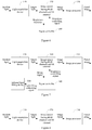
- the image fusion apparatus may include: a light acquisition device 110, an image processor 130, and an image sensor 120 having four types of photosensitive channels.
- the four types of photosensitive channels include red, green and blue RGB channels and an infrared IR channel.
- the light acquisition device 110 is configured to filter a spectrum component of a first predetermined wavelength range from incident light to obtain target light.
- the first predetermined wavelength range is a spectrum wavelength range in which a difference between the responsivities of the RGB channels and the responsivity of the IR channel in the image sensor 120 at an infrared band is greater than a first predetermined threshold.
- the image sensor 120 is configured to convert target light into an image signal through the RGB channels and the IR channel.
- the image processor 130 is configured to analyze the image signal into color signals and a brightness signal that is photosensitive to an infrared band, and fuse the color signals and the brightness signal to obtain a fused image.
- a color signal is a signal obtained based on the R channel, the G channel, or the B channel.
- the spectrum component of the first predetermined wavelength range is filtered out from the incident light, such that the portion in which there is a large difference between the quantum efficiencies of the channels at the near-infrared band is filtered out. This can simplify the operations performed by the image processor to remove the infrared component from the color signals, and thus improve the efficiency of the image fusion.
- the value of the first predetermined threshold may be set depending on actual conditions, and is not limited herein.
- the light acquisition device 110 will filter out the spectrum component of a corresponding wavelength range.
- the first predetermined wavelength range may be [T1, T2].
- the value of T1 is in the range of [600 nm, 800 nm]
- the value of T2 is in the range of [750 nm, 1100 nm]. It can be appreciated that, with the additional function of filtering the spectrum component of the predetermined wavelength range from the incident light, the spectrum component in which there is a large difference between the responsivities of the RGB channels and the responsivity of the IR channel in the image sensor 120, at the infrared band (650-1100 nm), is filtered out.
- the color signals and the brightness signal that is photosensitive to the infrared band can be precisely restored with simplified calculations from the image signal generated by the image sensor 120.
- the gray portion is the spectrum portion that needs to be filtered out.
- IR represents the infrared signal
- R represents the red light signal
- G represents the green light signal
- B represents the blue light signal.
- Figure 5 merely shows an example, which will not limit the embodiments of the present application. Due to manufacturing processes or the like, the actual filtered curves usually have slopes not as steep as those shown in Figure 5 .
- the Bayer pattern is a data format for image sensors.
- Figure 2 shows a schematic diagram of the Bayer pattern, which outputs the red, green, and blue dot matrix information in a mosaic manner.
- An image sensor based on Bayer pattern has only three channels, i.e., RGB channels, and cannot obtain the infrared spectrum component. Therefore, in order to obtain a fused image from a visible light image and an infrared image, a prism beam splitter, different optical sensors, and the like are required to simultaneously acquire infrared light and visible light, which results in a complex structure.
- an image sensor having four types of photosensitive channels is employed in the embodiments of the present application, such that color signals and a brightness signal that is photosensitive to an infrared band can be obtained from an image signal acquired by one single image sensor.
- the image sensor having the red, green and blue RGB channels and the infrared IR channel provided by the embodiments of the present application is referred to as an RGBIR image sensor.
- Figure 3 shows a diagram of an array corresponding to the RGBIR image sensor.
- the RGBIR image sensor includes four types of photosensitive channels, namely, RGB channels and an IR channel.
- the IR channel is photosensitive to the infrared band; the RGB channels are photosensitive to both visible light band and infrared band, and the RGB channels are primarily used to obtain visible light.
- the array shown in Figure 3 is merely for the purpose of illustration and should not be construed as limiting the embodiments of the present application.
- there are various arrays for the RGBIR image sensor all of which can be applied to the embodiments of the present application.
- the color signals can be generated by subtracting the value of an IR parameter for a pixel position from the value of the R channel, the G channel, or the B channel.
- the value of the IR parameter is the product of the value of the IR channel at the pixel position and a preset correction value. It can be appreciated that subtracting the value of the IR parameter for the pixel position respectively from the values of the R channel, G channel or B channel, namely removing the infrared component from the color signals, can avoid the crosstalk between the infrared component and the RGB signal components of the color signals, thereby improving the quality of the image obtained under low illumination.
- the preset correction value can be set depending on actual conditions. For example, the preset correction value can be generally set to 1.
- the preset correction value can also be set to any integer or fraction ranging from 0 to 1024 depending on actual conditions. Those skilled in the art can appreciate that the value of the preset correction value is not limited thereto.
- the process that the image processor 130 analyzes the image signal into the color signals and the brightness signal that is photosensitive to the infrared band includes:
- each small square corresponds to one pixel, and the resolution of the image signal generated by the RGBIR image sensor is 8 ⁇ 8, as shown in Figure 3 .
- the interpolation of the IR channel of the image signal generates the brightness signal having the resolution same as the input resolution and being photosensitive to the infrared band
- the brightness signal generated by the interpolation of the IR channel of the image signal as shown in Figure 3 also has a resolution of 8 ⁇ 8.
- the result of the interpolation of the IR channel may be as shown in Figure 4 .
- the interpolation of the IR channel of the image signal may be performed by an interpolation algorithm such as bilinear interpolation or bicubic interpolation, which is not limited herein.
- the resolution of the image signal generated by the RGBIR image sensor is related to the structure of the array.
- the resolution of 8 ⁇ 8 is only the resolution corresponding to the RGBIR image sensor having an array structure as shown in Figure 3 , which should not limit the embodiments of the present application.
- each small square may correspond to the R channel, the B channel, or the G channel. Therefore, when traversing the image signal, the R channel, the G channel or the B channel may be traversed and then the value of the IR parameter for the pixel position is subtracted from the value of the traversed R channel, the G channel, or the B channel to remove the infrared component.
- the respective interpolation algorithms used for the interpolations of the R channel, the G channel, and the B channel of the image signal may be such as bilinear interpolation or bicubic interpolation.
- the interpolation algorithm used for interpolation of the IR channel may or may not be the same as that used for the interpolations of the RGB channels, which will not be limited herein.
- the color signal generated by the interpolation of each of the R channel, the G channel and the B channel of the image signal has a resolution same as the input resolution.
- the resolution of the color signals generated by the interpolations of the RGB channels of the image signal is also 8 ⁇ 8.
- the image processor 130 analyzes the image signal into the color signals and the brightness signal that is photosensitive to the infrared band is merely an example and should not be construed as limitation of the embodiments of the present application.
- the process that the image processor 130 fuses the color signals and the brightness signal to obtain the fused image may include:
- the embodiments of the present application do not limit the values of the weights w1, w2, and w3.
- the process that the image processor 130 fuses the color signals and the brightness signal to obtain the fused image may include:
- Y represents Luminance or Luma, i.e., the value of the gray level
- U and V represent Chrominance or chroma which describe the color and saturation of the image and are used to specify the color of a pixel.
- the UV components may be subjected to noise reduction to remove color noise, which can improve the image quality of the fused image.
- the method for the noise reduction may include but is not limited to Gaussian filtering. It should be emphasized that the conversion between the YUV signals and the color signals can be implemented by any existing algorithm in the related art, and the extraction of the UV components from the YUV signals and the combination of the UV components and the brightness signal can be implemented by related techniques.
- the image processor 130 may first optimize the color signals and the brightness signal, and then fuse the optimized color signals and the optimized brightness signal to obtain the fused image.
- the optimization of the color signals may include performing low-pass filtering on the color signals to reduce the noise of the color signals.
- the optimization of the brightness signal may include performing high-pass filtering on the brightness signal to implement edge enhancement of the brightness signal.
- the light acquisition device filters the spectrum component of the first predetermined wavelength range from the incident light, so that the portion in which there is a large difference between the quantum efficiencies of the channels at the near-infrared band is filtered out.
- This can simplify the calculations performed by the image processor to remove the infrared component from the color signals, and thus improve the efficiency of the image fusion.
- the image fusion apparatus provided by the embodiment of the present application uses the image sensor having the four types of photosensitive channels to acquire images. Compared to means that requires special design on its optical system to simultaneously acquire infrared light and visible light, the complexity of the structure of the image fusion apparatus is greatly reduced, allowing the image fusion apparatus to be widely used.
- the light acquisition device 110 may include a band-stop filter and an optical lens of a first type.
- the optical lens of the first type is configured to transmit the incident light to the band-stop filter in a full spectrum transmission manner.
- the band-stop filter is configured to filter the spectrum component of the first predetermined wavelength range from the light transmitted from the optical lens of the first type to obtain the target light.
- the band-stop filter may be a coating integrated on the optical lens of the first type by coating; or the band-stop filter may be a patch disposed on the optical lens of the first type.
- the full spectrum transmission manner is a manner in which the spectrum components of all bands are transmitted, that is, no spectrum is filtered out. Since the optical lens of the first type transmits the incident light to the band-stop filter in a full-spectrum transmission manner, the light transmitted by the optical lens of the first type has a band same as the band of the incident light. That is, the optical lens of the first type does not filter the spectrum component of any band.
- the light acquisition device 110 includes an optical lens of a second type, which is capable of filtering the spectrum component of the first predetermined wavelength range.
- the specific implementation that the light acquisition device 110 filters the spectrum component of the first predetermined wavelength range from the incident light is merely an example, which do not constitute any limitation to the embodiments of the present application.
- the differences between responsivities of the RGB channels are lower than a second predetermined threshold, to ensure the precise restoration of color signals after the infrared component has been removed.
- the second predetermined wavelength range is [T3, T4], where T4 is greater than T3, T3 is greater than or equal to 750 nm, and T4 is less than or equal to 1100 nm.
- the responsivities of the RGB channels in the band at the right of the gray region satisfy a certain constraint.
- the second predetermined threshold may be set depending on actual conditions, which is not limited herein.
- the image sensor 120 may have different structures, to allow the differences between the responsivities of the RGB channels in the second predetermined wavelength range of the infrared band to be lower than the second predetermined threshold, which are not limited herein.
- a particular optical element such as a filter may be added to the image sensor.
- the process of converting the target light into the image signal may include that the image sensor 120 performs multiple-exposures acquisition in one frame time.
- one or multiple exposures can be manually set for the image sensor 120.
- the process that the image processor 130 analyzes the image signal into the color signals and the brightness signal that is photosensitive to the infrared band may include:
- the exposure of the first type and the exposure of the second type may or may not have same exposure duration.
- the exposure duration of the exposure of the first type may be less than the exposure duration of the exposure of the second type.
- the exposure duration of the exposure of the first type may also be greater than the exposure duration of the exposure of the second type.
- the operation of analyzing an image signal generated by using the exposure of the first type to obtain the color signals may include:
- the operation of analyzing the image signal generated by using the exposure of the second type to obtain the brightness signal that is photosensitive to the infrared band may specifically include: performing an interpolation operation on the IR channel of the image signal generated by using the exposure of the second type, to generate a brightness signal that has a resolution same as the input resolution and is photosensitive to the infrared band.
- the input resolution is the resolution of the image signal.
- interpolation of any of the channels involved in above processes may be performed with a bilinear interpolation or a bicubic interpolation algorithm, which is, of course, not limited thereto.
- an image signal generated with a short exposure may be analyzed to obtain the color signals and an image signal formed with a long exposure may be analyzed to obtain the brightness signal, so as to improve the image quality.
- the exposure duration of the exposure of the first type is less than the exposure duration of the exposure of the second type.
- an image fusion apparatus provided by an embodiment of the present application, as shown in Figure 6 , may further include: a signal controller 140, configured to control the image sensor 120 to generate an image signal that meets a predetermined brightness requirement.
- the signal controller may be specifically configured to analyze brightness of image signals generated by the image sensor 120, and control the image sensor 120 according to the analyzing result to generate image signals that meet the predetermined brightness requirement.
- the signal controller 140 may perform the following steps: (a) generating an initial brightness control signal and transmitting it to the image sensor 120; (b) calculating an average brightness of the image signals generated by the image sensor 120, that is, averaging that of all the pixel values; and (c) calculating the difference between the average brightness and a reference value, and if the difference is within a predetermined range, maintaining the value of the current brightness control signal unchanged; otherwise, if the difference is outside the predetermined range and greater than the reference value, lowering the value of the brightness control signal; and if the difference is outside the predetermined range and less than the reference value, increasing the value of the brightness control signal.
- the signal controller 140 can periodically send a predetermined brightness control signal to the image sensor 120.
- the predetermined brightness control signal is a control signal set according to a predetermined brightness requirement.
- the signal controller 140 can also be configured to control the image sensor 120 to switch between one-exposure acquisition and multiple-exposures acquisition. It should be emphasized that the specific implementation that the signal controller 140 controls the image sensor 120 to generate image signals that meet the predetermined brightness requirement is merely an example and should not be construed as limiting the embodiments of the present application.
- an image fusion apparatus provided by an embodiment of the present application may further include an infrared light filling device 150, as shown in Figure 7 .
- the signal controller 140 is further configured to control the infrared light filling device 150 to fill infrared light for the image sensor.
- the signal controller 140 can detect the gain value g of the brightness control signal.
- g is greater than a threshold T1
- a light-filling control signal is set to 1 to enable the infrared light filling.
- g is smaller than a threshold T2
- the light-filling control signal is set to 0 to disable the infrared light filling.
- T1 is greater than T2.
- T1 and T2 may be set depending on actual conditions, which are not limited herein.
- the above specific implementation that the signal controller 140 controls the infrared light filling device 150 to fill infrared light for the image sensor is merely for the purpose of illustration and should not be construed as limiting the embodiments of the present application.
- an embodiment of the present application provides an image fusion apparatus, to solve the problem of a low efficiency of image fusion due to a large amount of calculation performed by an image processor for removing an infrared component from color signals.
- the image fusion apparatus may include: a light acquisition device 210, an image processor 230, and an image sensor 220 having four types of photosensitive channels.
- the four types of photosensitive channels include red, green and blue RGB channels and a full-band W channel.
- the light acquisition device 210 is configured to filter a spectrum component of a first predetermined wavelength range from incident light to obtain target light.
- the first predetermined wavelength range is a spectrum wavelength range in which a difference between the responsivities of the RGB channels and the responsivity of the W channel in the image sensor 220 at an infrared band is greater than a first predetermined threshold.
- the image sensor 220 is configured to convert the target light into an image signal through the RGB channels and the W channel.
- the image processor 230 is configured to analyze the image signal into color signals and a brightness signal, and fuse the color signals and the brightness signal to obtain a fused image.
- a color signal is a signal obtained based on the R channel, the G channel, or the B channel.
- the spectrum component of the first predetermined wavelength range is filtered out from the incident light, such that the portion in which there is a large difference between the quantum efficiencies of the channels at the near-infrared band is filtered out. This can simplify the operations performed by the image processor to remove the infrared component from the color signals, and thus improve the efficiency of the image fusion.
- the value of the first predetermined threshold may be set depending on actual conditions, and is not limited herein.
- the light acquisition device 210 will filter the spectrum component of a corresponding wavelength range.
- the first predetermined wavelength range may be [T1, T2].
- the value of T1 is in the range of [600 nm, 800 nm]
- the value of T2 is in the range of [750 nm, 1100 nm]. It can be appreciated that, with the additional function of filtering the spectrum component of the predetermined wavelength range from the incident light, the spectrum component in which there is a large difference between the responsivities of the RGB channels and the responsivity of the W channel in the image sensor 220, at the infrared band (650-1100 nm), is filtered out.
- the color signals and the brightness signal can be precisely restored with simplified calculations from the image signal generated by the image sensor 220.
- the gray portion is the spectrum portion that needs to be filtered out.
- W represents the full-band spectrum signal
- R represents the red light signal
- G represents the green light signal
- B represents the blue light signal.
- Figure 13 merely shows an example, which will not limit the embodiments of the present application. Due to manufacturing processes or the like, the actual filtered curves usually have slopes not as steep as those shown in Figure 13 .
- the Bayer pattern is a data format for image sensors.
- Figure 2 shows a schematic diagram of the Bayer pattern, which outputs the red, green, and blue dot matrix information in a mosaic manner.
- An image sensor based Bayer pattern has only three channels, i.e., RGB channels, and cannot obtain the infrared spectrum component. Therefore, in order to obtain a fused image from a visible light image and an infrared image, a prism beam splitter, different optical sensors and the like are required to simultaneously acquire infrared light and visible light, which results in a complex structure.
- an image sensor having four types of photosensitive channels is employed in the embodiments of the present application, such that color signals and a brightness signal can be obtained from an image signal acquired by one single image sensor.
- the image sensor having the red, green and blue RGB channels and the full-band channel provided by the embodiments of the present application is referred to as an RGBW image sensor.
- FIG 9 shows schematic diagram of an array corresponding to the RGBW image sensor.
- the RGBW image sensor includes four types of photosensitive channels, namely, RGB channels and W channel.
- the W channel is a channel photosensitive to all bands. Since the W channel is photosensitive to all of the bands, it is photosensitive to the infrared band, and can be used as a brightness channel.
- the RGB channels are photosensitive to both visible band and infrared band, and are primarily used to obtained visible light.
- the array shown in Figure 9 is merely for the purpose of illustration and should not be construed as limiting the embodiments of the present application.
- the color signals can be generated by subtracting the value of an IR parameter for pixel position from the value of the R channel, the G channel, or the B channel.
- the value of the IR parameter is the product of an IR value for the pixel position and a second preset correction value.
- the IR value is a value calculated using a predetermined formula. It can be appreciated that subtracting the value of the IR parameter for pixel position respectively from the values of the traversed R channel, G channel, and B channel, namely removing the infrared component from the color signals, can avoid the crosstalk between the infrared component and the RGB signal components of the color signals, thereby improving the quality of the image obtained under low illumination.
- the first preset correction value and the second preset correction value can be set depending on actual conditions.
- the first preset correction value can be generally set to 2.
- the first preset correction value can be set to any integer or fraction ranging from 0 to 1024 depending on actual conditions.
- the value of the first preset correction value is not limited thereto.
- the second preset correction value can be generally set to 1.
- the second preset correction value can also be set to any integer or fraction ranging from 0 to 1024 depending on actual conditions.
- the value of the second preset correction value is not limited thereto.
- the process that the image processor 230 analyzes the image signal into the color signals and the brightness signal includes:
- each small square corresponds to one pixel, and the resolution of the image signal generated by the RGBW image sensor is 8 ⁇ 8, as shown in Figure 9 .
- the interpolation operation of the W channel of the image signal generates the brightness signal that has the resolution same as the input resolution
- the brightness signal generated by the interpolation of the W channel of the image signal shown in Figure 9 also has a resolution of 8 ⁇ 8.
- the result of the interpolation of the W channel may be as shown in Figure 10 .
- the interpolation of the W channel of the image signal may be implemented by an interpolation algorithm such as bilinear interpolation or bicubic interpolation, which is not limited herein.
- the resolution of the image signal generated by the RGBW image sensor is related to the structure of the array.
- the resolution of 8 ⁇ 8 is only the resolution corresponding to the RGBW image sensor having a structure of array shown in Figure 9 , which should not limit the embodiments of the present application.
- the R channel, the G channel, and the B channel of the image signal are respectively interpolated and an image signal of each of the channels has a resolution same as the input resolution is thus generated. Therefore, for example, the image signal of each of the channels generated by interpolating the R channel, the G channel, and the B channel of the image signal shown in Figure 9 has a resolution of 8 ⁇ 8.
- the respective interpolation algorithms used for implement the interpolation of the R channel, the G channel, or the B channel of the image signal may be bilinear interpolation or bicubic interpolation.
- the interpolation algorithm used for implement the interpolation of the W channel may or may not be same as that used for the interpolation of the RGB channels, which is not limited herein.
- the image processor 230 analyzes the image signal into the color signals and the brightness signal is merely an example and should not be construed as limitation of the embodiments of the present application.
- the process that the image processor 230 fuses the color signals and the brightness signal to obtain the fused image includes:
- the embodiments of the present application do not limit the values of the weights w1, w2, and w3.
- the process that the image processor 230 fuses the color signals and the brightness signal to obtain the fused image includes:
- Y represents Luminance (or Luma), i.e., the value of the gray level
- U represents Chrominance (or chroma) which describe the color and saturation of the image and are used to specify the color of a pixel.
- the UV components may be subjected to noise reduction to remove chroma noise, which improves the image quality of the fused image.
- the method for the noise reduction may include but is not limited to Gaussian filtering. It should be emphasized that the conversion between the YUV signals and the color signals can be implemented by any of existing conversion algorithms in the related art, and the extraction of the UV components from the YUV signals and the combination of the UV components with the brightness signal can be implemented by related techniques.
- the image processor 230 may first optimize the color signals and the brightness signal, and then fuse the optimized color signals and the optimized brightness signal to obtain the fused image.
- the optimization of the color signals may include performing low-pass filtering on the color signals to reduce the noise of the color signals.
- the optimization of the brightness signal may include performing high-pass filtering processing on the brightness signal to implement edge enhancement of the brightness signal.
- the light acquisition device filters the spectrum component of the first predetermined wavelength range from the incident light, so that the portion in which there is a large difference between the quantum efficiencies of the channels at the near-infrared band is filtered out.
- This can simplify the calculations performed by the image processor to remove the infrared component from the color signals, and thus improve the efficiency of the image fusion.
- the image fusion apparatus provided by the embodiment of the present application uses the image sensor having the four types of photosensitive channels to acquire images. Compared to means that requires special design on its optical system to simultaneously acquire infrared light and visible light, the complexity of the structure of the image fusion apparatus is greatly reduced, allowing the image fusion apparatus to be widely used.
- the light acquisition device 210 may include a band-stop filter and an optical lens of a first type.
- the optical lens of the first type is configured to transmit the incident light to the band-stop filter in a full spectrum transmission manner.
- the band-stop filter is configured to filter the spectrum component of the first predetermined wavelength range from the light transmitted from the optical lens of the first type to obtain the target light.
- the band-stop filter may be a coating integrated on the optical lens of the first type by coating; or the band-stop filter may be a patch disposed on the optical lens of the first type.
- the full spectrum transmission manner is a manner in which the spectrum components of all bands are transmitted, that is, no spectrum is filtered out. Since the optical lens of the first type transmits the incident light to the band-stop filter in a full-spectrum transmission manner, the light transmitted by the optical lens of the first type has a band same as the band of the incident light. That is, the optical lens of the first type does not filter the spectrum component of any band.
- the light acquisition device 210 includes an optical lens of a second type, which is capable of filtering the spectrum component of the first predetermined wavelength range.
- the specific implementation that the light acquisition device 210 filters the spectrum component of the first predetermined wavelength range from the incident light is merely an example, which do not constitute any limitation to the embodiments of the present application.
- the image sensor 220 converts the target light into the image signal, in a second predetermined wavelength range of the infrared band, the differences between responsivities of the RGB channels are lower than a second predetermined threshold, to ensure the precise restoration of color signals after the infrared component has been removed. This improves the quality of the image fusion.
- the second predetermined wavelength range is [T3, T4], where T4 is greater than T3, T3 is greater than or equal to 750 nm, and T4 is less than or equal to 1100 nm.
- T4 is greater than T3, T3 is greater than or equal to 750 nm, and T4 is less than or equal to 1100 nm.
- the second predetermined threshold may be set depending on actual conditions, which is not limited herein.
- the image sensor 220 may have different structures, to allow the differences between the responsivities of the RGB channels in the second predetermined wavelength range of the infrared band to be lower than the second predetermined threshold, which are not limited herein.
- a particular optical element such as a filter may be added to the image sensor.
- the process of converting the target light into the image signal may include that the image sensor 220 performs multiple-exposures acquisition in one frame time.
- one or multiple exposures can be manually set for the image sensor 220.
- the process that the image processor 230 analyzes the image signal into the color signals and the brightness signal may include:
- the exposure of the first type and the exposure of the second type may or may not have same exposure duration.
- the exposure duration of the exposure of the first type may be less than the exposure duration of the exposure of the second type.
- the exposure duration of the exposure of the first type may also be greater than the exposure duration of the exposure of the second type.
- the operation of analyzing an image signal generated by using the exposure of the first type to obtain the color signals may include:
- the operation of analyzing the image signal generated by using the exposure of the second type to obtain the brightness signal may specifically include: performing an interpolation operation on the W channel of the image signal generated by the exposure of the second type to generate the brightness signal that has a resolution same as an input resolution.
- the input resolution is the resolution of the image signal.
- interpolation of any of the channels involved in the above processes may be implemented by a bilinear interpolation or a bicubic interpolation, which is, of course, not limited thereto.
- an image fusion apparatus provided by an embodiment of the present application, as shown in Figure 11 , may further include: a signal controller 240, configured to control the image sensor 220 to generate an image signal that meets a predetermined brightness requirement.
- a signal controller 240 configured to control the image sensor 220 to generate an image signal that meets a predetermined brightness requirement.
- the signal controller 240 may be specifically configured to analyze brightness of image signals generated by the image sensor 220, and control the image sensor 220 according to the analyzing result to generate image signals that meet the predetermined brightness requirement. Specifically, the signal controller 240 may perform the following steps: (a) generating an initial brightness control signal and transmitting it to the image sensor 220; (b) calculating an average brightness of the image signals generated by the image sensor 220, that is, averaging that of all the pixel values; and (c) calculating the difference between the average brightness and a reference value, and if the difference is within a predetermined range, maintaining the value of the current brightness control signal unchanged; otherwise, if the difference is outside the predetermined range and greater than the reference value, lowering the value of the brightness control signal; and if the difference is outside the predetermined range and less than the reference value, increasing the value of the brightness control signal.
- the signal controller 240 can periodically send a predetermined brightness control signal to the image sensor 220.
- the predetermined brightness control signal is a control signal set according to a predetermined brightness requirement.
- the signal controller 240 can also be configured to control the image sensor 220 to switch between one-exposure acquisition and multiple-exposures acquisition. It should be emphasized that the specific implementation that the signal controller 240 controls the image sensor 220 to generate image signals that meet the predetermined brightness requirement is merely an example and should not be construed as limiting the embodiments of the present application.
- an image fusion apparatus provided by an embodiment of the present application may further include an infrared light filling device 250, as shown in Figure 12 .
- the signal controller 240 is further configured to control the infrared light filling device 250 to fill infrared light for the image sensor.
- the signal controller 240 can detect the gain value g of the brightness control signal.
- g is greater than a threshold T1
- a light-filling control signal is set to 1 to enable the infrared light filling.
- g is smaller than a threshold T2
- the light-filling control signal is set to 0 to disable the infrared light filling.
- T1 is greater than T2.
- T1 and T2 may be set depending on actual conditions, which are not limited herein.
- the above specific implementation that the signal controller 240 controls the infrared light filling device 250 to fill infrared light for the image sensor is merely for the purpose of illustration and should not be construed as limiting the embodiments of the present application.
- an embodiment of the present application further provides an image fusion method.
- the method is applicable to the image fusion apparatus provided by the first aspect of the embodiments of the present application.
- the image fusion apparatus has four types of photosensitive channels including red, green and blue RGB channels and an infrared IR channel. As shown in Figure 14 , the method includes the steps S1401-S1403.
- Step S1401 filtering a spectrum component of a first predetermined wavelength range from incident light to obtain target light; wherein the first predetermined wavelength range is a spectrum wavelength range in which a difference between responsivities of the RGB channels and a responsivity of the IR channel in an image sensor of the image fusion apparatus at an infrared band is greater than a first predetermined threshold.
- Step S1402 converting the target light into an image signal through the RGB channels and the IR channel.
- Step S1403 analyzing the image signal into color signals and a brightness signal that is photosensitive to the infrared band, and fusing the color signals and the brightness signal to obtain a fused image.
- a color signal is a signal obtained based on the R channel, the G channel, or the B channel.
- the spectrum component of the first predetermined wavelength range is filtered out from the incident light, such that the portion in which there is a large difference between the quantum efficiencies of the channels at the near-infrared band is filtered out.
- the value of the first predetermined threshold may be set depending on actual conditions, and is not limited herein.
- the first predetermined wavelength range may be [T1, T2].
- the value of T1 is in the range of [600 nm, 800 nm]
- the value of T2 is in the range of [750 nm, 1100 nm].
- the color signals can be generated by subtracting the value of an IR parameter for a pixel position from the value of the R channel, the G channel, or the B channel.
- the value of the IR parameter is the product of the value of the IR channel at the pixel position and a preset correction value. It can be appreciated that subtracting the value of the IR parameter for the pixel position respectively from the values of the R channel, G channel or B channel, namely removing the infrared component from the color signals, can avoid the crosstalk between the infrared component and the RGB signal components of the color signals, thereby improving the quality of the image obtained under low illumination.
- the preset correction value can be set depending on actual conditions.
- the preset correction value can be generally set to 1.
- the preset correction value can also be set to any integer or fraction ranging from 0 to 1024 depending on actual conditions. Those skilled in the art can appreciate that the value of the preset correction value is not limited thereto.
- the step of analyzing the image signal into the color signals and the brightness signal that is photosensitive to the infrared band may include:
- the step of fusing the color signals and the brightness signal to obtain the fused image may include:
- the step of fusing the color signals and the brightness signal to obtain the fused image include:
- multiple-exposures acquisition may be performed in one frame time.
- One or multiple exposures can be manually set, which is of course not limited thereto.
- the step of analyzing the image signal into the color signals and the brightness signal that is photosensitive to the infrared band may include:
- the exposure of the first type and the exposure of the second type may or may not have same exposure duration.
- the exposure duration of the exposure of the first type may be less than the exposure duration of the exposure of the second type.
- the exposure duration of the exposure of the first type may also be greater than the exposure duration of the exposure of the second type.
- the step of analyzing an image signal generated by using the exposure of the first type to obtain the color signals may include:
- the step of analyzing the image signal generated by using the exposure of the second type to obtain the brightness signal that is photosensitive to the infrared band may specifically include: performing an interpolation operation on the IR channel of the image signal generated by using the exposure of the second type, to generate a brightness signal that has a resolution same as the input resolution and is photosensitive to the infrared band.
- the input resolution is the resolution of the image signal.
- interpolation of any of the channels involved in above processes may be performed with a bilinear interpolation or a bicubic interpolation algorithm, which is, of course, not limited thereto.
- an image signal generated with a short exposure may be analyzed to obtain the color signals and an image signal formed with a long exposure may be analyzed to obtain the brightness signal, so as to improve the image quality.
- the exposure duration of the exposure of the first type is less than the exposure duration of the exposure of the second type.
- the image fusion method provided by the embodiments of the present application can reduce the amount of calculation for removing the infrared component from the color signals, which improves the efficiency of image fusion while achieves the objective of capturing a dual-band image through an image fusion apparatus having a simple structure.
- an embodiment of the present application further provides an image fusion method.
- the method is applicable to the image fusion apparatus provided by the embodiments of the present application in the second aspect.
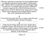
- the image fusion apparatus has four types of photosensitive channels, which include red, green and blue RGB channels and a full-band W channel. As shown in Figure 15 , the method includes the steps S1501-1503.
- Step S1501 filtering a spectrum component of a first predetermined wavelength range from incident light to obtain target light; wherein the first predetermined wavelength range is a spectrum wavelength range in which a difference between responsivities of the RGB channels and a responsivity of the W channel in an image sensor of the image fusion apparatus at an infrared band is greater than a first predetermined threshold.
- Step S1502 converting the target light into an image signal through the RGB channels and the W channel.
- Step S1503 analyzing the image signal into color signals and a brightness signal, and fusing the color signals and the brightness signal to obtain a fused image.
- a color signal is a signal obtained based on the R channel, the G channel, or the B channel.
- the spectrum component of the first predetermined wavelength range is filtered out from the incident light, such that the portion in which there is a large difference between the quantum efficiencies of the channels at the near-infrared band is filtered out. This can simplify the operations performed by the image processor to remove the infrared component from the color signals, and thus improve the efficiency of the image fusion.
- the value of the first predetermined threshold may be set depending on actual conditions, and is not limited herein.
- the first predetermined wavelength range may be [T1, T2].
- the value of T1 is in the range of [600 nm, 800 nm]
- the value of T2 is in the range of [750 nm, 1100 nm].
- a color signal can be generated by subtracting the value of an IR parameter for pixel position from the value of the R channel, the G channel, or the B channel.
- the value of the IR parameter is the product of an IR value for the pixel position and a second preset correction value.
- the IR value is a value calculated using a predetermined formula. It can be appreciated that subtracting the value of the IR parameter for pixel position respectively from the values of the traversed R channel, G channel, and B channel, namely removing the infrared component from the color signals, can avoid the crosstalk between the infrared component and the RGB signal components of the color signals, thereby improving the quality of the image obtained under low illumination.
- the first preset correction value and the second preset correction value can be set depending on actual conditions.
- the first preset correction value can be generally set to 2.
- the first preset correction value can be set to any integer or fraction ranging from 0 to 1024 depending on actual conditions.
- the value of the first preset correction value is not limited thereto.
- the second preset correction value can be generally set to 1.
- the second preset correction value can also be set to any integer or fraction ranging from 0 to 1024 depending on actual conditions. Those skilled in the art can appreciate that the value of the second preset correction value is not limited thereto.
- the step of analyzing the image signal into the color signals and the brightness signal that is photosensitive to the infrared band includes:
- the process of fusing the color signals and the brightness signal to obtain the fused image may include:
- the step of fusing the color signals and the brightness signal to obtain the fused image may include:
- multiple-exposures acquisition may be performed in one frame time.
- One or multiple exposures can be manually set, which is of course not limited thereto.
- the step of analyzing the image signal into the color signals and the brightness signal that is photosensitive to the infrared band may include:
- the exposure of the first type and the exposure of the second type may or may not have same exposure duration.
- the exposure duration of the exposure of the first type may be less than the exposure duration of the exposure of the second type.
- the exposure duration of the exposure of the first type may also be greater than the exposure duration of the exposure of the second type.
- the step of analyzing the image signal generated by using an exposure of the first type to obtain the color signals may include:
- the step of analyzing the image signal generated by using an exposure of the second type to obtain a brightness signal may specifically include:
- the image fusion method provided by the embodiments of the present application can reduce the amount of calculation for removing the infrared component from the color signals, which improves the fusion efficiency and achieves the objective of capturing a dual-band image through an image fusion apparatus with a simple structure at the same time.
- an embodiment of the present application further provides a storage medium for storing executable program codes.
- the executable program codes are executed to perform steps of any one of the image fusion methods provided by the embodiments in the above third aspect.
- the amount of calculation for removing the infrared component from the color signals can be reduced, which improves the fusion efficiency and achieves the objective of capturing a dual-band image through an image fusion apparatus with a simple structure at the same time.
- an embodiment of the present application provides a storage medium for storing executable codes.
- the executable codes are executed to perform steps of any one of the image fusion methods provided by the embodiments in the above fourth aspect.
- the amount of calculation for removing the infrared component from the color signals can be reduced, which improves the fusion efficiency and achieves the objective of capturing a dual-band image through an image fusion apparatus with a simple structure at the same time.
- an embodiment of the present application provides an application program for performing, when executed, steps of any of the image fusion methods provided by above method embodiments.
- the application program provided by the embodiment of the present application when executed on the image fusion apparatus provided in the first aspect, can reduce the amount of calculation for removing the infrared component from the color signals, which improves the fusion efficiency and achieves the objective of capturing a dual-band image through an image fusion apparatus with a simple structure at the same time.
- an embodiment of the present application provides an application program for performing, when executed, steps of any of the image fusion methods provided by the above method embodiments.
- the application program provided by the embodiment of the present application when executed on the image fusion apparatus provided in the second aspect, can reduce the amount of calculation for removing the infrared component from the color signals, which improves the fusion efficiency and achieves the objective of capturing a dual-band image through an image fusion apparatus with a simple structure at the same time.
- first type "second type”, “third type”, “fourth type”, “first” and “second” involved in the embodiments herein are only used to identify different objects of the same category in terms of naming, so that the objects can be easily and clearly referred to. Such wording does not have any limiting meaning.
- the various embodiments herein are described in a related manner, and the same or similar parts of the embodiments may be referred to each other, and the description for each embodiment focuses on the a part different from that of the other embodiments.
- the apparatus/device embodiments are basically similar to the method embodiments, the description for the former is relatively simple, and the relevant parts can be referred to the description of the method embodiment.
Landscapes
- Engineering & Computer Science (AREA)
- Multimedia (AREA)
- Signal Processing (AREA)
- Physics & Mathematics (AREA)
- Spectroscopy & Molecular Physics (AREA)
- General Physics & Mathematics (AREA)
- Theoretical Computer Science (AREA)
- Human Computer Interaction (AREA)
- Color Television Image Signal Generators (AREA)
- Studio Devices (AREA)
Claims (14)
- Appareil de fusion d'images, comprenant :un dispositif d'acquisition de lumière (110, 210), un processeur d'image (130, 230) et un capteur d'image (120, 220) qui a quatre types de canaux photosensibles, les quatre types de canaux photosensibles comprenant des canaux RGB rouge, vert et bleu et un canal IR infrarouge, ou les quatre types de canaux photosensibles comprenant les canaux RGB et un canal W pleine bande ; dans lequelle dispositif d'acquisition de lumière (110, 210) est configuré pour supprimer une composante de spectre dans une première plage de longueur d'onde prédéterminée de lumière incidente pour obtenir de la lumière cible ; dans lequel la première plage de longueur d'onde prédéterminée est une plage de longueur d'onde de spectre dans laquelle une différence entre les sensibilités des canaux RGB et une sensibilité du canal IR ou du canal W dans le capteur d'image (120, 220) à une bande infrarouge est supérieure à un premier seuil prédéterminé (S1401, S1501) ;le capteur d'images (120, 220) est configuré pour convertir la lumière de la cible en un signal d'image par les canaux RGB et le canal IR ou le canal W (S1401, S1501) ; etle processeur d'images (130, 230) est configuré pour analyser le signal d'image en signaux de couleur et en un signal de luminosité photosensible à la bande infrarouge et, dans le cas du canal W, également dans une bande visible, et pour fusionner les signaux de couleur et le signal de luminosité pour obtenir une image fusionnée, dans lequel les signaux de couleur sont des signaux obtenus sur la base du canal R, du canal G ou du canal B (S1403, S1503),dans lequel le processus, selon lequel le processeur d'images (130, 230) fusionne les signaux de couleur et le signal de luminosité pour obtenir l'image fusionnée (S1403, S1503), comprend :le calcul d'une valeur auxiliaire Y pour chaque pixel en fonction des signaux de couleur, comme Y=(R*w1+G*w2+B*w3)/(w1+w2+w3), dans lequel R est une valeur du canal R du pixel, G est une valeur du canal G du pixel, B est une valeur du canal B du pixel, et w1, w2 et w3 sont des poids ;le calcul d'un rapport entre la valeur de chaque canal des signaux de couleur et la valeur auxiliaire Y pour obtenir des valeurs de canal de référence K1, K2 et K3 du pixel, qui sont K1=R/Y, K2=G/Y, K3=B/Y ;l'exécution d'une réduction du bruit de chrominance sur les valeurs de canal de référence K1, K2, et K3 ; etla fusion d'une valeur de luminosité Y' du pixel, qui est une valeur du signal de luminosité qui est photosensible à la bande infrarouge, et les valeurs des canaux de référence K1-K3 qui ont été soumises à la réduction du bruit de chrominance, pour générer des valeurs des canaux RGB fusionnés R', G' et B' et pour obtenir l'image fusionnée ; dans lesquelles R'=K1*Y' ; G'=K2*Y' ; B'=K3*Y'.
- Appareil de fusion d'images selon la revendication 1, dans lequel le signal de couleur est généré en soustrayant une valeur d'un paramètre IR pour une position de pixel d'une valeur du canal R, du canal G ou du canal B, dans lequel,
lorsque les quatre types de canaux photosensibles comprennent les canaux RGB et le canal IR, la valeur du paramètre IR est un produit d'une valeur du canal IR à la position du pixel et d'une valeur de correction préétablie ; et
lorsque les quatre types de canaux photosensibles comprennent les canaux RGB et le canal W, la valeur du paramètre IR est un produit d'une valeur IR pour la position du pixel et d'une deuxième valeur de correction préétablie, dans lequel la valeur IR est une valeur calculée par une formule prédéterminée. - Appareil de fusion d'images selon la revendication 2, dans lequel, lorsque les quatre types de canaux photosensibles comprennent les canaux RGB et le canal IR, le processus, selon lequel le processeur d'images (130, 230) analyse le signal d'image en signaux de couleur et le signal de luminosité (S1403, S1503), comprend :l'exécution d'une opération d'interpolation sur le canal IR du signal d'image pour générer un signal de luminosité qui a une résolution identique à une résolution d'entrée et qui est photosensible à la bande infrarouge, dans lequel la résolution d'entrée est une résolution du signal d'image,la traversée du signal d'image et la soustraction d'une valeur d'un paramètre IR pour une position de pixel d'une valeur du canal R, du canal G ou du canal B traversé, dans lequel la valeur du paramètre IR est un produit d'une valeur du canal IR à la position du pixel et d'une valeur de correction préétablie; etl'exécution d'opérations d'interpolation sur le canal R, le canal G et le canal B du signal d'image, respectivement, pour générer les signaux de couleur ayant une résolution qui est identique à la résolution d'entrée.
- Appareil de fusion d'images selon la revendication 2, dans lequel, lorsque les quatre types de canaux photosensibles comprennent les canaux RGB et le canal W, le processus selon lequel le processeur d'images (130, 230) analyse le signal d'image en signaux de couleur et le signal de luminosité (S1403, S1503), comprend :l'exécution d'une opération d'interpolation sur le canal W du signal d'image pour générer un signal de luminosité qui a une résolution identique à une résolution d'entrée, dans laquelle la résolution d'entrée est une résolution du signal d'image ;l'exécution d'opérations d'interpolation sur le canal R, le canal G et le canal B du signal d'image, respectivement, pour générer un signal d'image de chacun des canaux RGB qui a une résolution identique à la résolution d'entrée ;la traversée du signal d'image de chacun des canaux et le calcul d'une valeur IR pour chaque position de pixel par une formule prédéterminée, qui est (R+G+B-W)/n, dans laquelle R est une valeur du canal R du pixel, G est une valeur du canal G du pixel, B est une valeur du canal B du pixel, W est une valeur du canal W du pixel, et n est une première valeur de correction préétablie ; etla traversée du signal d'image de chacun des canaux, et la soustraction d'une valeur d'un paramètre IR pour une position de pixel d'une valeur du canal R, du canal G ou du canal B traversé pour générer un signal de couleur, dans lequel la valeur du paramètre IR est un produit d'une valeur IR pour la position de pixel et d'une deuxième valeur de correction préétablie.
- Appareil de fusion d'images selon l'une quelconque des revendications 1 à 4, dans lequel le dispositif d'acquisition de lumière (110, 210) comprend un filtre coupe-bande et une lentille optique d'un premier type ; dans lequel
la lentille optique du premier type est configurée pour transmettre la lumière incidente au filtre coupe-bande dans un mode de transmission à spectre complet ; et
le filtre coupe-bande est configuré pour éliminer la composante du spectre dans la première gamme de longueur d'onde prédéterminée de la lumière transmise par la lentille optique du premier type pour obtenir la lumière cible,
ou
dans lequel le dispositif d'acquisition de lumière (110, 210) comprend une lentille optique d'un second type, qui est capable d'éliminer la composante du spectre dans la première gamme de longueur d'onde prédéterminée. - Appareil de fusion d'images selon l'une quelconque des revendications 1 à 4, dans lequel la première plage de longueur d'onde prédéterminée est [T1 , T2], dans lequel la valeur de T1 est dans une plage de [600 nm, 800 nm], et la valeur de T2 est dans une plage de [750 nm, 1100 nm],
ou
dans lequel, pendant la conversion de la lumière cible en signal d'image par le capteur d'image (120, 220), dans une deuxième plage de longueur d'onde prédéterminée de la bande infrarouge, les différences entre les sensibilités des canaux RGB sont inférieures à un deuxième seuil prédéterminé, dans lequel la deuxième plage de longueur d'onde prédéterminée est [T3, T4], dans laquelle T4 est supérieure à T3, T3 est supérieure ou égale à 750 nm et T4 est inférieure ou égale à 1100 nm. - Appareil de fusion d'images selon l'une quelconque des revendications 1 à 4, dans lequel le processus selon lequel le capteur d'images (120, 220) convertit la lumière de la cible en signal d'image (S1402, S1502) comprend le fait que le capteur d'images (120, 220) effectue des acquisitions d'expositions multiples dans une temps d'image.
- Appareil de fusion d'images selon la revendication 7, dans lequel le processus que le processeur d'images (130, 230) analyse le signal d'image en signaux de couleur et le signal de luminosité qui est photosensible à la bande infrarouge (S1403, S1503), comprend :l'analyse d'un signal d'image généré en utilisant une exposition d'un premier type pour obtenir les signaux de couleur ; etl'analyse d'un signal d'image généré en utilisant une exposition d'un second type pour obtenir le signal de luminosité, dans laquelle lorsque les quatre types de canaux photosensibles comprennent les canaux RGB et le canal IR, le signal de luminosité est un signal de luminosité qui est photosensible à la bande,dans laquelle la durée d'exposition du premier type est inférieure à celle de l'exposition du second type.
- Appareil de fusion d'images selon l'une quelconque des revendications 1 à 4, comprenant en outre un contrôleur de signal (140, 240), configuré pour commander le capteur d'images (120, 220) afin de générer un signal d'image qui répond à une exigence de luminosité prédéterminée.
- Appareil de fusion d'images selon la revendication 9, dans lequel le contrôleur de signaux (140, 240) est en outre configuré pour analyser la luminosité des signaux d'image générés par le capteur d'images (120, 220) et pour commander le capteur d'images (120, 220) selon un résultat d'analyse afin de générer le signal d'image qui répond à l'exigence de luminosité prédéterminée,
ou
dans lequel le contrôleur de signaux (140, 240) est en outre configuré pour commander le capteur d'images (120, 220) afin de commuter entre une acquisition d'une seule exposition et une acquisition d'expositions multiples,
ou
dans lequel l'appareil comprend en outre un dispositif de remplissage à lumière infrarouge (150, 250) ; dans lequel le contrôleur de signaux (140, 240) est en outre configuré pour commander le dispositif de remplissage à lumière infrarouge (1 50, 250) pour remplir la lumière infrarouge pour le capteur d'images (120, 220). - Procédé de fusion d'images, qui est applicable à un appareil de fusion d'images qui a quatre types de canaux photosensibles, les quatre types de canaux photosensibles comprenant des canaux RGB rouge, vert et bleu et un canal IR infrarouge, ou les quatre types de canaux photosensibles comprenant les canaux RGB et un canal W pleine bande ; le procédé comprenant :la suppression d'une composante du spectre dans une première plage de longueur d'onde prédéterminée de lumière incidente pour obtenir une lumière cible, dans lequel la première plage de longueur d'onde prédéterminée est une plage de longueur d'onde du spectre dans laquelle une différence entre les sensibilités des canaux RGB et une sensibilité du canal IR ou du canal W dans un capteur d'image (120, 220) de l'appareil de fusion d'image à une bande infrarouge est supérieure à un premier seuil prédéterminé (S1401, S1501) ; la conversion de la lumière cible en un signal d'image par les canaux RGB et le canal IR ou le canal W (S1402, S1502) ; etl'analyse du signal d'image en signaux de couleur et en un signal de luminosité qui est photosensible à la bande infrarouge et, dans le cas du canal W, également à une bande visible, et la fusion des signaux de couleur et du signal de luminosité pour obtenir une image fusionnée, dans laquelle les signaux de couleur sont des signaux obtenus sur la base du canal R, du canal G ou du canal B (1403, S1503),dans laquelle l'étape consistant à fusionner les signaux de couleur et le signal de luminosité pour obtenir l'image fusionnée (S1403, S1503), comprendle calcul d'une valeur auxiliaire Y pour chaque pixel en fonction des signaux de couleur, comme Y=(R*w1+G*w2+B*w3)/(w1+w2+w3), dans laquelle R est une valeur du canal R du pixel, G est une valeur du canal G du pixel, B est une valeur du canal B du pixel, et w1, w2 et w3 sont des poids ;le calcul d'un rapport entre la valeur de chaque canal des signaux de couleur et la valeur auxiliaire Y pour obtenir les valeurs de canal de référence K1, K2 et K3 pour le pixel, qui sont K1=R/Y, K2=G/Y, K3=B/Y ;l'exécution d'une réduction du bruit de chrominance sur les valeurs de canal de référence K1, K2, et K3, etla fusion d'une valeur de luminosité Y' du pixel, qui est une valeur du signal de luminosité photosensible à la bande infrarouge, et les valeurs des canaux de référence K1-K3 qui ont été soumises à la réduction du bruit de chrominance, pour générer les valeurs des canaux RGB fusionnés R', G' et B' et pour obtenir l'image fusionnée, dans lesquelles R'=K1*Y' ; G'=K2*Y' ; B'=K3*Y'.
- Procédé selon la revendication 11, dans lequel le signal de couleur est généré en soustrayant une valeur d'un paramètre IR pour une position de pixel d'une valeur du canal R, du canal G ou du canal B, dans lequel,
lorsque les quatre types de canaux photosensibles comprennent les canaux RGB et le canal IR, la valeur du paramètre IR est un produit d'une valeur du canal IR à la position du pixel et d'une valeur de correction de préréglage ; et
lorsque les quatre types de canaux photosensibles comprennent les canaux RGB et le canal W, la valeur du paramètre IR est un produit d'une valeur IR pour la position du pixel et d'une deuxième valeur de correction préétablie, dans lequel la valeur est une valeur calculée par une formule prédéterminée. - Procédé selon la revendication 12, dans lequel, lorsque les quatre types de canaux photosensibles comprennent les canaux RGB et le canal IR, l'étape d'analyse du signal de l'image en signaux de couleur et en signal de luminosité (S1403 S1503), comprend :l'exécution d'une opération d'interpolation sur le canal du signal d'image pour générer un signal de luminosité qui a une résolution identique à une résolution d'entrée et qui est photosensible à la bande infrarouge, dans lequel la résolution d'entrée est une résolution du signal d'image,la traversée du signal d'image et la soustraction d'une valeur d'un paramètre IR pour une position de pixel d'une valeur du canal R, du canal G ou du canal B traversé, dans laquelle la valeur du paramètre IR est un produit d'une valeur du canal IR à la position du pixel et d'une valeur de correction préétablie ; etl'exécution des opérations d'interpolation sur le canal R, le canal G et le canal B du signal d'image, respectivement, pour générer les signaux de couleur qui ont une résolution identique à la résolution d'entrée.
- Procédé selon la revendication 12, dans lequel, lorsque les quatre types de canaux photosensibles comprennent les canaux RGB et le canal W, l'étape d'analyse du signal d'image en signaux de couleur et en signal de luminosité (S1403, S1503), comprend :l'exécution d'une opération d'interpolation sur le canal W du signal d'image pour générer un signal de luminosité qui a une résolution identique à une résolution d'entrée, dans laquelle la résolution d'entrée est une résolution le signal d'image ;l'exécution d'opérations d'interpolation sur le canal R, le canal G et le canal B du signal d'image respectivement, pour générer des signaux d'image de chacun des canaux RGB qui a une résolution identique à la résolution d'entrée ;la traversée du signal d'image de chacun des canaux, et le calcul d'une valeur IR pour chaque position de pixel par une formule prédéterminée, qui est (R+G+B-W)/n, dans laquelle R est une valeur du canal R du pixel, G est une valeur du canal G du pixel, B est une valeur du canal B du pixel, W est une valeur du canal W du pixel, et n est une première valeur de correction préétablie ; etla traversée du signal d'image de chacun des canaux, et la soustraction d'une valeur d'un paramètre IR pour une position de pixel d'une valeur du canal R, du canal G ou du canal B traversé pour générer un signal de couleur, dans laquelle la valeur du paramètre IR est un produit d'une valeur IR pour la position du pixel et une deuxième valeur de correction préétablie.
Applications Claiming Priority (2)
| Application Number | Priority Date | Filing Date | Title |
|---|---|---|---|
| CN201710074203.9A CN108419062B (zh) | 2017-02-10 | 2017-02-10 | 图像融合设备和图像融合方法 |
| PCT/CN2018/074093 WO2018145575A1 (fr) | 2017-02-10 | 2018-01-25 | Appareil de fusion d'image et procédé de fusion d'image |
Publications (3)
| Publication Number | Publication Date |
|---|---|
| EP3582490A1 EP3582490A1 (fr) | 2019-12-18 |
| EP3582490A4 EP3582490A4 (fr) | 2020-02-26 |
| EP3582490B1 true EP3582490B1 (fr) | 2021-07-07 |
Family
ID=63107165
Family Applications (1)
| Application Number | Title | Priority Date | Filing Date |
|---|---|---|---|
| EP18750832.0A Active EP3582490B1 (fr) | 2017-02-10 | 2018-01-25 | Appareil de fusion d'image et procédé de fusion d'image |
Country Status (4)
| Country | Link |
|---|---|
| US (1) | US11049232B2 (fr) |
| EP (1) | EP3582490B1 (fr) |
| CN (2) | CN111988587B (fr) |
| WO (1) | WO2018145575A1 (fr) |
Families Citing this family (64)
| Publication number | Priority date | Publication date | Assignee | Title |
|---|---|---|---|---|
| JP2017099616A (ja) * | 2015-12-01 | 2017-06-08 | ソニー株式会社 | 手術用制御装置、手術用制御方法、およびプログラム、並びに手術システム |
| WO2017149932A1 (fr) * | 2016-03-03 | 2017-09-08 | ソニー株式会社 | Dispositif de traitement d'image médicale, système, procédé et programme |
| CN108419061B (zh) * | 2017-02-10 | 2020-10-02 | 杭州海康威视数字技术股份有限公司 | 基于多光谱的图像融合设备、方法及图像传感器 |
| CN111988587B (zh) * | 2017-02-10 | 2023-02-07 | 杭州海康威视数字技术股份有限公司 | 图像融合设备和图像融合方法 |
| CN109508588A (zh) * | 2017-09-15 | 2019-03-22 | 杭州海康威视数字技术股份有限公司 | 监控方法、装置、系统、电子设备及计算机可读存储介质 |
| KR102412278B1 (ko) * | 2017-11-06 | 2022-06-24 | 삼성전자 주식회사 | 보색관계의 필터 어레이를 포함하는 카메라 모듈 및 그를 포함하는 전자 장치 |
| EP4513424A3 (fr) | 2018-05-25 | 2025-04-30 | Fluke Corporation | Systèmes et procédé d'imagerie de gaz optique compatibles avec des caméras d'imagerie thermique non refroidies |
| TWI694721B (zh) * | 2018-10-08 | 2020-05-21 | 瑞昱半導體股份有限公司 | 紅外線串擾補償方法及其裝置 |
| CN109377468A (zh) * | 2018-10-09 | 2019-02-22 | 湖南源信光电科技股份有限公司 | 基于多特征的红外辐射和偏振图像的伪彩色融合方法 |
| WO2020113404A1 (fr) * | 2018-12-04 | 2020-06-11 | 深圳市大疆创新科技有限公司 | Procédé d'obtention d'image cible, dispositif de photographie et véhicule aérien sans pilote |
| CN110493532B (zh) * | 2018-12-12 | 2021-06-29 | 杭州海康威视数字技术股份有限公司 | 一种图像处理方法和系统 |
| CN111951200B (zh) * | 2019-05-15 | 2023-11-14 | 杭州海康威视数字技术股份有限公司 | 摄像设备、图像融合方法、装置和存储介质 |
| CN110490041B (zh) * | 2019-05-31 | 2022-03-15 | 杭州海康威视数字技术股份有限公司 | 人脸图像采集装置及方法 |
| CN110493494B (zh) | 2019-05-31 | 2021-02-26 | 杭州海康威视数字技术股份有限公司 | 图像融合装置及图像融合方法 |
| CN110493491B (zh) * | 2019-05-31 | 2021-02-26 | 杭州海康威视数字技术股份有限公司 | 一种图像采集装置及摄像方法 |
| CN110493492B (zh) * | 2019-05-31 | 2021-02-26 | 杭州海康威视数字技术股份有限公司 | 图像采集装置及图像采集方法 |
| CN110493537B (zh) * | 2019-06-14 | 2022-08-02 | 杭州海康威视数字技术股份有限公司 | 图像采集装置及图像采集方法 |
| CN110519489B (zh) * | 2019-06-20 | 2021-04-06 | 杭州海康威视数字技术股份有限公司 | 图像采集方法及装置 |
| CN110290370B (zh) * | 2019-07-05 | 2020-09-18 | 上海富瀚微电子股份有限公司 | 图像处理方法及装置 |
| CN112217962B (zh) * | 2019-07-10 | 2022-04-05 | 杭州海康威视数字技术股份有限公司 | 摄像机及图像生成方法 |
| CN112241668B (zh) * | 2019-07-18 | 2024-06-28 | 杭州海康威视数字技术股份有限公司 | 图像处理方法、装置及设备 |
| WO2021016900A1 (fr) * | 2019-07-31 | 2021-02-04 | 华为技术有限公司 | Capteur d'image et procédé de photodétection d'image |
| CN110544225A (zh) * | 2019-08-08 | 2019-12-06 | 北京首贝科技发展有限公司 | 一种基于弱计算能力的轻量化图像融合算法与装置 |
| CN110507283A (zh) * | 2019-09-17 | 2019-11-29 | 福州鑫图光电有限公司 | 视网膜相机及其实现方法 |
| CN113163124B (zh) * | 2020-01-22 | 2022-06-03 | 杭州海康威视数字技术股份有限公司 | 一种成像系统及图像处理方法 |
| CN113271414B (zh) | 2020-02-14 | 2022-11-18 | 上海海思技术有限公司 | 图像获取方法和装置 |
| CN111402306A (zh) * | 2020-03-13 | 2020-07-10 | 中国人民解放军32801部队 | 一种基于深度学习的微光/红外图像彩色融合方法及系统 |
| CN113469160B (zh) * | 2020-03-30 | 2024-03-12 | 浙江宇视科技有限公司 | 一种不可见光分量的去除方法、装置、存储介质及设备 |
| EP4131916A4 (fr) * | 2020-04-29 | 2023-05-17 | Huawei Technologies Co., Ltd. | Caméra et procédé d'acquisition d'image |
| CN111507930B (zh) * | 2020-06-18 | 2023-10-10 | 杭州海康威视数字技术股份有限公司 | 图像融合方法、装置、存储介质和计算机设备 |
| CN111741277B (zh) * | 2020-07-13 | 2022-04-29 | 深圳市汇顶科技股份有限公司 | 图像处理的方法和图像处理装置 |
| JP7496183B2 (ja) * | 2020-08-05 | 2024-06-06 | パナソニックオートモーティブシステムズ株式会社 | 撮像装置 |
| WO2022027469A1 (fr) * | 2020-08-06 | 2022-02-10 | 深圳市汇顶科技股份有限公司 | Procédé et appareil de traitement d'image et support de stockage |
| US11689822B2 (en) * | 2020-09-04 | 2023-06-27 | Altek Semiconductor Corp. | Dual sensor imaging system and privacy protection imaging method thereof |
| CN114143443B (zh) * | 2020-09-04 | 2024-04-05 | 聚晶半导体股份有限公司 | 双传感器摄像系统及其摄像方法 |
| CN112163627B (zh) * | 2020-10-09 | 2024-01-23 | 北京环境特性研究所 | 目标物体的融合图像生成方法、装置及系统 |
| WO2022103429A1 (fr) * | 2020-11-12 | 2022-05-19 | Innopeak Technology, Inc. | Fusion d'images avec décomposition des détails de base et ajustement flexible des couleurs et des détails |
| WO2021184029A1 (fr) | 2020-11-12 | 2021-09-16 | Innopeak Technology, Inc. | Systèmes et procédés de fusion d'une image couleur et d'une image proche infrarouge |
| WO2021184028A1 (fr) * | 2020-11-12 | 2021-09-16 | Innopeak Technology, Inc. | Défloutage à l'aide d'un équilibrage automatique des blancs localisé |
| CN114612369A (zh) * | 2020-12-04 | 2022-06-10 | 深圳超多维科技有限公司 | 图像融合方法、装置及电子设备 |
| CN114697584B (zh) * | 2020-12-31 | 2023-12-26 | 杭州海康威视数字技术股份有限公司 | 一种图像处理系统及图像处理方法 |
| CN114697586B (zh) * | 2020-12-31 | 2023-12-29 | 杭州海康威视数字技术股份有限公司 | 一种图像处理系统、近红外光补光控制方法及装置 |
| CN112819738B (zh) * | 2021-01-19 | 2024-01-02 | 合肥英睿系统技术有限公司 | 红外图像融合方法、装置、计算机设备和存储介质 |
| CN112884688B (zh) * | 2021-02-03 | 2024-03-29 | 浙江大华技术股份有限公司 | 一种图像融合方法、装置、设备及介质 |
| CN113115012B (zh) * | 2021-04-06 | 2022-09-13 | 展讯通信(上海)有限公司 | 图像处理方法及相关装置 |
| CN113298192A (zh) * | 2021-07-07 | 2021-08-24 | 思特威(上海)电子科技股份有限公司 | 红外光图像与可见光图像的融合方法、装置及存储介质 |
| US12148124B2 (en) | 2021-07-15 | 2024-11-19 | Samsung Electronics Co., Ltd. | Apparatus and method for combined intraband and interband multi-frame demosaicing |
| US12254601B2 (en) * | 2021-07-15 | 2025-03-18 | Samsung Electronics Co., Ltd. | Apparatus and method for interband denoising and sharpening of images |
| CN113567357B (zh) * | 2021-07-26 | 2024-05-24 | 杭州海康威视数字技术股份有限公司 | 一种光谱数据的融合方法、以及装置 |
| CN113781326B (zh) * | 2021-08-11 | 2024-11-22 | 北京旷视科技有限公司 | 解马赛克方法、装置、电子设备及存储介质 |
| CN113824936B (zh) * | 2021-09-23 | 2024-02-09 | 合肥埃科光电科技股份有限公司 | 色彩滤波阵列线扫描相机色彩插值方法、装置及设备 |
| CN114466122A (zh) * | 2022-01-25 | 2022-05-10 | 江西绿萌科技控股有限公司 | 一种多光谱摄像装置及其方法 |
| CN114841904B (zh) * | 2022-03-03 | 2024-10-22 | 浙江大华技术股份有限公司 | 图像融合方法、电子设备及存储装置 |
| CN114708181B (zh) * | 2022-04-18 | 2025-03-07 | 烟台艾睿光电科技有限公司 | 图像融合方法、装置、设备和存储介质 |
| CN114693580B (zh) * | 2022-05-31 | 2022-10-18 | 荣耀终端有限公司 | 图像处理方法及其相关设备 |
| CN114936174B (zh) * | 2022-06-09 | 2024-01-30 | 中国兵器工业计算机应用技术研究所 | 基于地面无人平台的图像处理与融合计算方法 |
| CN114881904B (zh) * | 2022-06-10 | 2025-03-07 | 深圳市汇顶科技股份有限公司 | 图像处理方法、图像处理装置及芯片 |
| CN114782502B (zh) * | 2022-06-16 | 2022-11-04 | 浙江宇视科技有限公司 | 一种多光谱多传感器协同处理方法及装置、存储介质 |
| CN115409754B (zh) * | 2022-11-02 | 2023-03-24 | 深圳深知未来智能有限公司 | 一种基于图像区域有效性的多曝光图像融合方法及系统 |
| CN117115061B (zh) * | 2023-09-11 | 2024-04-09 | 北京理工大学 | 一种多模态图像融合方法、装置、设备及存储介质 |
| CN117676120B (zh) * | 2023-12-14 | 2025-03-28 | 深圳市眼科医院(深圳市眼病防治研究所) | 一种用于扩大视野缺损患者视野范围的智能助视眼镜 |
| CN120602792A (zh) * | 2024-02-27 | 2025-09-05 | 荣耀终端股份有限公司 | 一种基于rgbw传感器的成像方法及相关设备 |
| CN120047324B (zh) * | 2025-02-14 | 2025-09-19 | 珠江水利委员会珠江水利科学研究院 | 基于广义植被盖度的乘积融合方法、系统、设备及存储介质 |
| CN120339146B (zh) * | 2025-06-20 | 2025-08-29 | 青蓝集创医疗设备(成都)有限公司 | 一种图像处理方法及系统 |
Family Cites Families (23)
| Publication number | Priority date | Publication date | Assignee | Title |
|---|---|---|---|---|
| JP4695550B2 (ja) * | 2006-06-22 | 2011-06-08 | 富士フイルム株式会社 | 固体撮像装置およびその駆動方法 |
| US8520970B2 (en) * | 2010-04-23 | 2013-08-27 | Flir Systems Ab | Infrared resolution and contrast enhancement with fusion |
| JP5670456B2 (ja) * | 2009-08-25 | 2015-02-18 | アイピーリンク・リミテッド | カラー画像のノイズを低減すること |
| US8619143B2 (en) * | 2010-03-19 | 2013-12-31 | Pixim, Inc. | Image sensor including color and infrared pixels |
| US8408821B2 (en) * | 2010-10-12 | 2013-04-02 | Omnivision Technologies, Inc. | Visible and infrared dual mode imaging system |
| JP2014515587A (ja) * | 2011-06-01 | 2014-06-30 | ザ ボード オブ トラスティーズ オブ ザ レランド スタンフォード ジュニア ユニバーシティー | デジタル画像装置用の画像処理パイプラインの学習 |
| US9177988B2 (en) * | 2011-12-16 | 2015-11-03 | Chromatra, Llc. | Systems and methods for creating full-color image in low light |
| US9173570B2 (en) * | 2012-04-12 | 2015-11-03 | Thomas Nathan Millikan | Viewing and processing multispectral images |
| US20140218598A1 (en) * | 2013-02-07 | 2014-08-07 | Power Lens Technology Inc. | Lens assembly applicable to an image sensor |
| US9497429B2 (en) * | 2013-03-15 | 2016-11-15 | Pelican Imaging Corporation | Extended color processing on pelican array cameras |
| US9692992B2 (en) * | 2013-07-01 | 2017-06-27 | Omnivision Technologies, Inc. | Color and infrared filter array patterns to reduce color aliasing |
| US9992469B2 (en) * | 2014-06-24 | 2018-06-05 | Hitachi Maxell, Ltd. | Imaging processing device and imaging processing method |
| CN105323567B (zh) | 2014-07-11 | 2017-07-28 | 恒景科技股份有限公司 | 色彩处理系统及装置 |
| JP6664122B2 (ja) * | 2014-08-20 | 2020-03-13 | パナソニックIpマネジメント株式会社 | 固体撮像装置及びカメラ |
| JP6568719B2 (ja) * | 2014-08-29 | 2019-08-28 | 株式会社 日立産業制御ソリューションズ | 撮像方法及び撮像装置 |
| US9570491B2 (en) | 2014-10-08 | 2017-02-14 | Omnivision Technologies, Inc. | Dual-mode image sensor with a signal-separating color filter array, and method for same |
| US20160161332A1 (en) * | 2014-12-09 | 2016-06-09 | Stmicroelectronics (Research & Development) Limited | Image sensor using pixels with combined rgb and ir sensing |
| CN104683767B (zh) * | 2015-02-10 | 2018-03-06 | 浙江宇视科技有限公司 | 透雾图像生成方法及装置 |
| KR102287944B1 (ko) * | 2015-12-22 | 2021-08-09 | 삼성전자주식회사 | 영상 출력 장치 및 영상 출력 방법 |
| EP3433816A1 (fr) * | 2016-03-22 | 2019-01-30 | URU, Inc. | Appareils, systèmes et procédés pour intégrer un contenu multimédia numérique dans un autre contenu multimédia numérique |
| WO2018120238A1 (fr) * | 2016-12-30 | 2018-07-05 | 华为技术有限公司 | Dispositif et procédé de traitement de fichiers, et interface utilisateur graphique |
| CN111988587B (zh) * | 2017-02-10 | 2023-02-07 | 杭州海康威视数字技术股份有限公司 | 图像融合设备和图像融合方法 |
| CN108419061B (zh) * | 2017-02-10 | 2020-10-02 | 杭州海康威视数字技术股份有限公司 | 基于多光谱的图像融合设备、方法及图像传感器 |
-
2017
- 2017-02-10 CN CN202010866072.XA patent/CN111988587B/zh active Active
- 2017-02-10 CN CN201710074203.9A patent/CN108419062B/zh active Active
-
2018
- 2018-01-25 WO PCT/CN2018/074093 patent/WO2018145575A1/fr not_active Ceased
- 2018-01-25 US US16/481,397 patent/US11049232B2/en active Active
- 2018-01-25 EP EP18750832.0A patent/EP3582490B1/fr active Active
Non-Patent Citations (1)
| Title |
|---|
| None * |
Also Published As
| Publication number | Publication date |
|---|---|
| CN108419062B (zh) | 2020-10-02 |
| CN108419062A (zh) | 2018-08-17 |
| CN111988587B (zh) | 2023-02-07 |
| US20190378258A1 (en) | 2019-12-12 |
| EP3582490A1 (fr) | 2019-12-18 |
| EP3582490A4 (fr) | 2020-02-26 |
| WO2018145575A1 (fr) | 2018-08-16 |
| CN111988587A (zh) | 2020-11-24 |
| US11049232B2 (en) | 2021-06-29 |
Similar Documents
| Publication | Publication Date | Title |
|---|---|---|
| EP3582490B1 (fr) | Appareil de fusion d'image et procédé de fusion d'image | |
| EP3582494B1 (fr) | Appareil et procédé de fusion d'image multispectrale, et capteur d'image | |
| CN102204258B (zh) | 图像输入装置 | |
| US20100182478A1 (en) | Image Processing Device, Imaging Device, Image Processing Method, Imaging Method, And Image Processing Program | |
| US9936172B2 (en) | Signal processing device, signal processing method, and signal processing program for performing color reproduction of an image | |
| US20080068477A1 (en) | Solid-state imaging device | |
| CN114422766B (zh) | 一种图像采集设备 | |
| KR101923957B1 (ko) | 감도 개선을 위한 영상 처리 장치 및 방법 | |
| EP2418856A1 (fr) | Dispositif d'entrée d'image | |
| US9060159B2 (en) | Image processing device and method, and imaging device | |
| US10395347B2 (en) | Image processing device, imaging device, image processing method, and image processing program | |
| US7697044B2 (en) | Image processing apparatus and image processing method | |
| US9131199B2 (en) | Imaging apparatus capable of generating an appropriate color image | |
| CN101473658B (zh) | 摄像系统和摄像方法 | |
| US10326947B2 (en) | Image processing device, imaging device, image processing method, and program | |
| US8704925B2 (en) | Image sensing apparatus including a single-plate image sensor having five or more brands | |
| KR20240105257A (ko) | 이미지의 색 재현 방법 및 장치 | |
| US11190713B2 (en) | Image processing apparatus and method, and imaging apparatus | |
| KR100999885B1 (ko) | 이미지 신호 처리 장치, 이미지 신호 처리 장치의 색 노이즈 저감 방법 및 색 노이즈 저감 방법이 기록된 기록 매체 |
Legal Events
| Date | Code | Title | Description |
|---|---|---|---|
| STAA | Information on the status of an ep patent application or granted ep patent |
Free format text: STATUS: THE INTERNATIONAL PUBLICATION HAS BEEN MADE |
|
| PUAI | Public reference made under article 153(3) epc to a published international application that has entered the european phase |
Free format text: ORIGINAL CODE: 0009012 |
|
| STAA | Information on the status of an ep patent application or granted ep patent |
Free format text: STATUS: REQUEST FOR EXAMINATION WAS MADE |
|
| 17P | Request for examination filed |
Effective date: 20190801 |
|
| AK | Designated contracting states |
Kind code of ref document: A1 Designated state(s): AL AT BE BG CH CY CZ DE DK EE ES FI FR GB GR HR HU IE IS IT LI LT LU LV MC MK MT NL NO PL PT RO RS SE SI SK SM TR |
|
| AX | Request for extension of the european patent |
Extension state: BA ME |
|
| A4 | Supplementary search report drawn up and despatched |
Effective date: 20200127 |
|
| RIC1 | Information provided on ipc code assigned before grant |
Ipc: H04N 5/353 20110101ALI20200121BHEP Ipc: H04N 5/33 20060101AFI20200121BHEP Ipc: H04N 9/04 20060101ALI20200121BHEP Ipc: G06T 3/40 20060101ALI20200121BHEP |
|
| DAV | Request for validation of the european patent (deleted) | ||
| DAX | Request for extension of the european patent (deleted) | ||
| GRAP | Despatch of communication of intention to grant a patent |
Free format text: ORIGINAL CODE: EPIDOSNIGR1 |
|
| STAA | Information on the status of an ep patent application or granted ep patent |
Free format text: STATUS: GRANT OF PATENT IS INTENDED |
|
| INTG | Intention to grant announced |
Effective date: 20201210 |
|
| GRAJ | Information related to disapproval of communication of intention to grant by the applicant or resumption of examination proceedings by the epo deleted |
Free format text: ORIGINAL CODE: EPIDOSDIGR1 |
|
| STAA | Information on the status of an ep patent application or granted ep patent |
Free format text: STATUS: REQUEST FOR EXAMINATION WAS MADE |
|
| GRAP | Despatch of communication of intention to grant a patent |
Free format text: ORIGINAL CODE: EPIDOSNIGR1 |
|
| STAA | Information on the status of an ep patent application or granted ep patent |
Free format text: STATUS: GRANT OF PATENT IS INTENDED |
|
| INTC | Intention to grant announced (deleted) | ||
| INTG | Intention to grant announced |
Effective date: 20210420 |
|
| GRAS | Grant fee paid |
Free format text: ORIGINAL CODE: EPIDOSNIGR3 |
|
| GRAA | (expected) grant |
Free format text: ORIGINAL CODE: 0009210 |
|
| STAA | Information on the status of an ep patent application or granted ep patent |
Free format text: STATUS: THE PATENT HAS BEEN GRANTED |
|
| AK | Designated contracting states |
Kind code of ref document: B1 Designated state(s): AL AT BE BG CH CY CZ DE DK EE ES FI FR GB GR HR HU IE IS IT LI LT LU LV MC MK MT NL NO PL PT RO RS SE SI SK SM TR |
|
| REG | Reference to a national code |
Ref country code: GB Ref legal event code: FG4D |
|
| REG | Reference to a national code |
Ref country code: AT Ref legal event code: REF Ref document number: 1409745 Country of ref document: AT Kind code of ref document: T Effective date: 20210715 |
|
| REG | Reference to a national code |
Ref country code: DE Ref legal event code: R096 Ref document number: 602018019795 Country of ref document: DE |
|
| REG | Reference to a national code |
Ref country code: IE Ref legal event code: FG4D |
|
| REG | Reference to a national code |
Ref country code: LT Ref legal event code: MG9D |
|
| REG | Reference to a national code |
Ref country code: NL Ref legal event code: MP Effective date: 20210707 |
|
| REG | Reference to a national code |
Ref country code: AT Ref legal event code: MK05 Ref document number: 1409745 Country of ref document: AT Kind code of ref document: T Effective date: 20210707 |
|
| PG25 | Lapsed in a contracting state [announced via postgrant information from national office to epo] |
Ref country code: LT Free format text: LAPSE BECAUSE OF FAILURE TO SUBMIT A TRANSLATION OF THE DESCRIPTION OR TO PAY THE FEE WITHIN THE PRESCRIBED TIME-LIMIT Effective date: 20210707 Ref country code: BG Free format text: LAPSE BECAUSE OF FAILURE TO SUBMIT A TRANSLATION OF THE DESCRIPTION OR TO PAY THE FEE WITHIN THE PRESCRIBED TIME-LIMIT Effective date: 20211007 Ref country code: AT Free format text: LAPSE BECAUSE OF FAILURE TO SUBMIT A TRANSLATION OF THE DESCRIPTION OR TO PAY THE FEE WITHIN THE PRESCRIBED TIME-LIMIT Effective date: 20210707 Ref country code: NO Free format text: LAPSE BECAUSE OF FAILURE TO SUBMIT A TRANSLATION OF THE DESCRIPTION OR TO PAY THE FEE WITHIN THE PRESCRIBED TIME-LIMIT Effective date: 20211007 Ref country code: PT Free format text: LAPSE BECAUSE OF FAILURE TO SUBMIT A TRANSLATION OF THE DESCRIPTION OR TO PAY THE FEE WITHIN THE PRESCRIBED TIME-LIMIT Effective date: 20211108 Ref country code: NL Free format text: LAPSE BECAUSE OF FAILURE TO SUBMIT A TRANSLATION OF THE DESCRIPTION OR TO PAY THE FEE WITHIN THE PRESCRIBED TIME-LIMIT Effective date: 20210707 Ref country code: HR Free format text: LAPSE BECAUSE OF FAILURE TO SUBMIT A TRANSLATION OF THE DESCRIPTION OR TO PAY THE FEE WITHIN THE PRESCRIBED TIME-LIMIT Effective date: 20210707 Ref country code: FI Free format text: LAPSE BECAUSE OF FAILURE TO SUBMIT A TRANSLATION OF THE DESCRIPTION OR TO PAY THE FEE WITHIN THE PRESCRIBED TIME-LIMIT Effective date: 20210707 Ref country code: ES Free format text: LAPSE BECAUSE OF FAILURE TO SUBMIT A TRANSLATION OF THE DESCRIPTION OR TO PAY THE FEE WITHIN THE PRESCRIBED TIME-LIMIT Effective date: 20210707 Ref country code: SE Free format text: LAPSE BECAUSE OF FAILURE TO SUBMIT A TRANSLATION OF THE DESCRIPTION OR TO PAY THE FEE WITHIN THE PRESCRIBED TIME-LIMIT Effective date: 20210707 Ref country code: RS Free format text: LAPSE BECAUSE OF FAILURE TO SUBMIT A TRANSLATION OF THE DESCRIPTION OR TO PAY THE FEE WITHIN THE PRESCRIBED TIME-LIMIT Effective date: 20210707 |
|
| PG25 | Lapsed in a contracting state [announced via postgrant information from national office to epo] |
Ref country code: PL Free format text: LAPSE BECAUSE OF FAILURE TO SUBMIT A TRANSLATION OF THE DESCRIPTION OR TO PAY THE FEE WITHIN THE PRESCRIBED TIME-LIMIT Effective date: 20210707 Ref country code: LV Free format text: LAPSE BECAUSE OF FAILURE TO SUBMIT A TRANSLATION OF THE DESCRIPTION OR TO PAY THE FEE WITHIN THE PRESCRIBED TIME-LIMIT Effective date: 20210707 Ref country code: GR Free format text: LAPSE BECAUSE OF FAILURE TO SUBMIT A TRANSLATION OF THE DESCRIPTION OR TO PAY THE FEE WITHIN THE PRESCRIBED TIME-LIMIT Effective date: 20211008 |
|
| REG | Reference to a national code |
Ref country code: DE Ref legal event code: R097 Ref document number: 602018019795 Country of ref document: DE |
|
| PG25 | Lapsed in a contracting state [announced via postgrant information from national office to epo] |
Ref country code: DK Free format text: LAPSE BECAUSE OF FAILURE TO SUBMIT A TRANSLATION OF THE DESCRIPTION OR TO PAY THE FEE WITHIN THE PRESCRIBED TIME-LIMIT Effective date: 20210707 |
|
| PLBE | No opposition filed within time limit |
Free format text: ORIGINAL CODE: 0009261 |
|
| STAA | Information on the status of an ep patent application or granted ep patent |
Free format text: STATUS: NO OPPOSITION FILED WITHIN TIME LIMIT |
|
| PG25 | Lapsed in a contracting state [announced via postgrant information from national office to epo] |
Ref country code: SM Free format text: LAPSE BECAUSE OF FAILURE TO SUBMIT A TRANSLATION OF THE DESCRIPTION OR TO PAY THE FEE WITHIN THE PRESCRIBED TIME-LIMIT Effective date: 20210707 Ref country code: SK Free format text: LAPSE BECAUSE OF FAILURE TO SUBMIT A TRANSLATION OF THE DESCRIPTION OR TO PAY THE FEE WITHIN THE PRESCRIBED TIME-LIMIT Effective date: 20210707 Ref country code: RO Free format text: LAPSE BECAUSE OF FAILURE TO SUBMIT A TRANSLATION OF THE DESCRIPTION OR TO PAY THE FEE WITHIN THE PRESCRIBED TIME-LIMIT Effective date: 20210707 Ref country code: EE Free format text: LAPSE BECAUSE OF FAILURE TO SUBMIT A TRANSLATION OF THE DESCRIPTION OR TO PAY THE FEE WITHIN THE PRESCRIBED TIME-LIMIT Effective date: 20210707 Ref country code: CZ Free format text: LAPSE BECAUSE OF FAILURE TO SUBMIT A TRANSLATION OF THE DESCRIPTION OR TO PAY THE FEE WITHIN THE PRESCRIBED TIME-LIMIT Effective date: 20210707 Ref country code: AL Free format text: LAPSE BECAUSE OF FAILURE TO SUBMIT A TRANSLATION OF THE DESCRIPTION OR TO PAY THE FEE WITHIN THE PRESCRIBED TIME-LIMIT Effective date: 20210707 |
|
| 26N | No opposition filed |
Effective date: 20220408 |
|
| PG25 | Lapsed in a contracting state [announced via postgrant information from national office to epo] |
Ref country code: IT Free format text: LAPSE BECAUSE OF FAILURE TO SUBMIT A TRANSLATION OF THE DESCRIPTION OR TO PAY THE FEE WITHIN THE PRESCRIBED TIME-LIMIT Effective date: 20210707 |
|
| PG25 | Lapsed in a contracting state [announced via postgrant information from national office to epo] |
Ref country code: MC Free format text: LAPSE BECAUSE OF FAILURE TO SUBMIT A TRANSLATION OF THE DESCRIPTION OR TO PAY THE FEE WITHIN THE PRESCRIBED TIME-LIMIT Effective date: 20210707 |
|
| REG | Reference to a national code |
Ref country code: CH Ref legal event code: PL |
|
| REG | Reference to a national code |
Ref country code: BE Ref legal event code: MM Effective date: 20220131 |
|
| PG25 | Lapsed in a contracting state [announced via postgrant information from national office to epo] |
Ref country code: LU Free format text: LAPSE BECAUSE OF NON-PAYMENT OF DUE FEES Effective date: 20220125 |
|
| PG25 | Lapsed in a contracting state [announced via postgrant information from national office to epo] |
Ref country code: BE Free format text: LAPSE BECAUSE OF NON-PAYMENT OF DUE FEES Effective date: 20220131 |
|
| PG25 | Lapsed in a contracting state [announced via postgrant information from national office to epo] |
Ref country code: LI Free format text: LAPSE BECAUSE OF NON-PAYMENT OF DUE FEES Effective date: 20220131 Ref country code: CH Free format text: LAPSE BECAUSE OF NON-PAYMENT OF DUE FEES Effective date: 20220131 |
|
| PG25 | Lapsed in a contracting state [announced via postgrant information from national office to epo] |
Ref country code: IE Free format text: LAPSE BECAUSE OF NON-PAYMENT OF DUE FEES Effective date: 20220125 |
|
| P01 | Opt-out of the competence of the unified patent court (upc) registered |
Effective date: 20230424 |
|
| PG25 | Lapsed in a contracting state [announced via postgrant information from national office to epo] |
Ref country code: MK Free format text: LAPSE BECAUSE OF FAILURE TO SUBMIT A TRANSLATION OF THE DESCRIPTION OR TO PAY THE FEE WITHIN THE PRESCRIBED TIME-LIMIT Effective date: 20210707 Ref country code: CY Free format text: LAPSE BECAUSE OF FAILURE TO SUBMIT A TRANSLATION OF THE DESCRIPTION OR TO PAY THE FEE WITHIN THE PRESCRIBED TIME-LIMIT Effective date: 20210707 |
|
| PG25 | Lapsed in a contracting state [announced via postgrant information from national office to epo] |
Ref country code: HU Free format text: LAPSE BECAUSE OF FAILURE TO SUBMIT A TRANSLATION OF THE DESCRIPTION OR TO PAY THE FEE WITHIN THE PRESCRIBED TIME-LIMIT; INVALID AB INITIO Effective date: 20180125 |
|
| PG25 | Lapsed in a contracting state [announced via postgrant information from national office to epo] |
Ref country code: MT Free format text: LAPSE BECAUSE OF FAILURE TO SUBMIT A TRANSLATION OF THE DESCRIPTION OR TO PAY THE FEE WITHIN THE PRESCRIBED TIME-LIMIT Effective date: 20210707 |
|
| PG25 | Lapsed in a contracting state [announced via postgrant information from national office to epo] |
Ref country code: TR Free format text: LAPSE BECAUSE OF FAILURE TO SUBMIT A TRANSLATION OF THE DESCRIPTION OR TO PAY THE FEE WITHIN THE PRESCRIBED TIME-LIMIT Effective date: 20210707 |
|
| PGFP | Annual fee paid to national office [announced via postgrant information from national office to epo] |
Ref country code: GB Payment date: 20260127 Year of fee payment: 9 |
|
| PGFP | Annual fee paid to national office [announced via postgrant information from national office to epo] |
Ref country code: DE Payment date: 20260114 Year of fee payment: 9 |
|
| PGFP | Annual fee paid to national office [announced via postgrant information from national office to epo] |
Ref country code: FR Payment date: 20260128 Year of fee payment: 9 |