EP3582744B1 - Dispositif de gastrostomie pourvu d'un élément de retenue amélioré - Google Patents
Dispositif de gastrostomie pourvu d'un élément de retenue amélioré Download PDFInfo
- Publication number
- EP3582744B1 EP3582744B1 EP17719902.3A EP17719902A EP3582744B1 EP 3582744 B1 EP3582744 B1 EP 3582744B1 EP 17719902 A EP17719902 A EP 17719902A EP 3582744 B1 EP3582744 B1 EP 3582744B1
- Authority
- EP
- European Patent Office
- Prior art keywords
- tube
- retaining element
- gastrostomy device
- gastrostomy
- distal end
- Prior art date
- Legal status (The legal status is an assumption and is not a legal conclusion. Google has not performed a legal analysis and makes no representation as to the accuracy of the status listed.)
- Active
Links
Images






Classifications
-
- A—HUMAN NECESSITIES
- A61—MEDICAL OR VETERINARY SCIENCE; HYGIENE
- A61J—CONTAINERS SPECIALLY ADAPTED FOR MEDICAL OR PHARMACEUTICAL PURPOSES; DEVICES OR METHODS SPECIALLY ADAPTED FOR BRINGING PHARMACEUTICAL PRODUCTS INTO PARTICULAR PHYSICAL OR ADMINISTERING FORMS; DEVICES FOR ADMINISTERING FOOD OR MEDICINES ORALLY; BABY COMFORTERS; DEVICES FOR RECEIVING SPITTLE
- A61J15/00—Feeding-tubes for therapeutic purposes
- A61J15/0026—Parts, details or accessories for feeding-tubes
- A61J15/003—Means for fixing the tube inside the body, e.g. balloons, retaining means
- A61J15/0046—Expandable retainers inside body lumens of the enteral tract, e.g. fixing by radially contacting a lumen wall
- A61J15/0049—Inflatable Balloons
-
- A—HUMAN NECESSITIES
- A61—MEDICAL OR VETERINARY SCIENCE; HYGIENE
- A61J—CONTAINERS SPECIALLY ADAPTED FOR MEDICAL OR PHARMACEUTICAL PURPOSES; DEVICES OR METHODS SPECIALLY ADAPTED FOR BRINGING PHARMACEUTICAL PRODUCTS INTO PARTICULAR PHYSICAL OR ADMINISTERING FORMS; DEVICES FOR ADMINISTERING FOOD OR MEDICINES ORALLY; BABY COMFORTERS; DEVICES FOR RECEIVING SPITTLE
- A61J15/00—Feeding-tubes for therapeutic purposes
- A61J15/0015—Gastrostomy feeding-tubes
-
- A—HUMAN NECESSITIES
- A61—MEDICAL OR VETERINARY SCIENCE; HYGIENE
- A61J—CONTAINERS SPECIALLY ADAPTED FOR MEDICAL OR PHARMACEUTICAL PURPOSES; DEVICES OR METHODS SPECIALLY ADAPTED FOR BRINGING PHARMACEUTICAL PRODUCTS INTO PARTICULAR PHYSICAL OR ADMINISTERING FORMS; DEVICES FOR ADMINISTERING FOOD OR MEDICINES ORALLY; BABY COMFORTERS; DEVICES FOR RECEIVING SPITTLE
- A61J15/00—Feeding-tubes for therapeutic purposes
- A61J15/0015—Gastrostomy feeding-tubes
- A61J15/0023—Gastrostomy feeding-tubes inserted by using a sheath
-
- A—HUMAN NECESSITIES
- A61—MEDICAL OR VETERINARY SCIENCE; HYGIENE
- A61J—CONTAINERS SPECIALLY ADAPTED FOR MEDICAL OR PHARMACEUTICAL PURPOSES; DEVICES OR METHODS SPECIALLY ADAPTED FOR BRINGING PHARMACEUTICAL PRODUCTS INTO PARTICULAR PHYSICAL OR ADMINISTERING FORMS; DEVICES FOR ADMINISTERING FOOD OR MEDICINES ORALLY; BABY COMFORTERS; DEVICES FOR RECEIVING SPITTLE
- A61J2205/00—General identification or selection means
- A61J2205/40—General identification or selection means by shape or form, e.g. by using shape recognition
-
- A—HUMAN NECESSITIES
- A61—MEDICAL OR VETERINARY SCIENCE; HYGIENE
- A61M—DEVICES FOR INTRODUCING MEDIA INTO, OR ONTO, THE BODY; DEVICES FOR TRANSDUCING BODY MEDIA OR FOR TAKING MEDIA FROM THE BODY; DEVICES FOR PRODUCING OR ENDING SLEEP OR STUPOR
- A61M25/00—Catheters; Hollow probes
- A61M25/10—Balloon catheters
- A61M2025/1043—Balloon catheters with special features or adapted for special applications
- A61M2025/1075—Balloon catheters with special features or adapted for special applications having a balloon composed of several layers, e.g. by coating or embedding
-
- A—HUMAN NECESSITIES
- A61—MEDICAL OR VETERINARY SCIENCE; HYGIENE
- A61M—DEVICES FOR INTRODUCING MEDIA INTO, OR ONTO, THE BODY; DEVICES FOR TRANSDUCING BODY MEDIA OR FOR TAKING MEDIA FROM THE BODY; DEVICES FOR PRODUCING OR ENDING SLEEP OR STUPOR
- A61M25/00—Catheters; Hollow probes
- A61M25/01—Introducing, guiding, advancing, emplacing or holding catheters
- A61M25/02—Holding devices, e.g. on the body
- A61M25/04—Holding devices, e.g. on the body in the body, e.g. expansible
Definitions
- the present invention relates to a gastrostomy device, and in particular to a gastrostomy device for percutaneous endoscopic gastrostomy (PEG), which has a double-layered retaining element for holding the gastrostomy device in place.
- PEG percutaneous endoscopic gastrostomy
- the abdominal wall and the stomach is punctured with a trocar.
- a distal end of the PEG tube is then inserted into the stomach.
- a balloon at the distal end of the PEG tube and an external retainer slidably arranged on the PEG tube hold the PEG tube in place and pull the stomach wall and abdominal wall together.
- Such balloon as well as the PEG tube are usually made of a silicone material, which allows flexibility for the PEG tube and due to the prolongation of the silicone material an inflatable and self-deflating balloon.
- US 8,177,742 B1 relates to an inflatable retention system for an enteral feeding device including an inflatable balloon having a predetermined full volume.
- the balloon may be made of PU, PVC or PA or other materials as well as admixtures or blends of these materials.
- the inflatable balloon may stretch or distend, e.g. about 10% to 15% deformation depending on the pressure of the inflated balloon.
- a gastrostomy device comprises a gastrostomy tube and an inflatable retaining element coupled to the tube at or near a distal end of the tube.
- the retaining element comprises an inner layer made of polyurethane, PUR (or PU), and an outer layer made of polyamide, PA.
- a preferable material for the inner layer is "Elastollan ® 1198A 10".
- a preferable material is "Vestamid ® Care ME62” being a polyether block amide, which is a thermoplastic elastomer made of flexible polyether and rigid polyamide. Both materials are preferably transparent and clear, but alternatively can be at least partially opaque and/or colored.
- the inflatable retaining element can be formed by co-extrusion of PUR and PA, so that a double-layered tube is fabricated, where the PUR forms an inner layer and the PA forms an outer layer.
- Such double-layered tube is then widened at a certain portion thereof, for example, by inflating the certain portion of the tube into a mold. Before widening the double-layer tube it is advantageous to warm the double-layer tube, so that the PUR and PA layers can expand as uniformly as possible.
- the double-layered tube can be elongated or stretch formed before widening.
- a diameter thereof can be adapted (reduced), so that the double-layered tube fits onto the tube of the gastrostomy device, i.e. an inner diameter of the double-layered tube corresponds to an outer diameter of the tube of the gastrostomy device.
- the mold is provided with an inner surface having the form of the resulting retaining element.
- the mold consists of one or more parts.
- the double-layered tube can be put into a first part and one or more further parts are closed over the double-layered tube to form the complete mold.
- the mold can be warmed, thereby avoiding instant curing or hardening of the double-layered tube during widening.
- the retaining element can be taken out of the mold. Any remaining parts of the double-layered tube at one or both ends of the retaining element can be cut to a desired length.
- the inner layer made of PUR of the tube may have a thickness of 0.1 mm to 0.3 mm, preferably 0.2 mm, and the outer layer made of PA may have a thickness of 0.05 mm to 0.2 mm, preferably 0.1 mm. After elongating or stretching the tube the combined thickness of the inner and outer layer may be reduced to 0.1 mm to 0.35 mm, but may be preferably 0.15 mm.
- the thickness of the inner and/or outer layer will be reduced. Since the retaining element has increased dimensions compared to the tube (e.g. an increased diameter), the thickness of the inner and outer layer will approximately linearly decrease from a portion where the tube is not widened to a radially outer most portion of the widened tube. For instance, at the radially outer most portion the combined thickness of the inner and outer layers may be as small as approximately 0.025 mm. As an example only, the thickness of the inner layer may be reduced to 0.02 mm and the thickness of the outer layer may be reduced to 0.005 mm due to the widening.
- Such thin layers provide for an easy to fold retaining element that, when in an empty state, does not require much space.
- the outer layer made of PA increases the durability of the retaining element. Specifically, the mechanical prolongation of PA is less than that of PUR.
- the retaining element when inflated, the retaining element will achieve the desired form and will maintain this form if mechanical influences from the stomach or movement of the torso of the patient are acting on the retaining element.
- the retaining element made of PUR and PA provides the advantage that in case of a small leakage it will maintain its form over a longer period of time and, hence, will retain the gastrostomy device in position for a longer period of time.
- Such retaining element made of PUR and PA has a small extensibility. For instance, an elastic elongation of the retaining element is considerably below 30%.
- a conventional silicone balloon can be squeezed (deformed) by external influences which may decrease a secure retaining of the gastrostomy device.
- due to the elasticity and very low tear strength of silicone a small hole or a mechanical damage like a scratch in a silicone balloon will lead to an immediate balloon burst and, therefore, a sudden pressure loss as the fluid within the balloon will be squeezed out very quickly.
- a silicone balloon may be elastically elongated easily above 500%. Thus, the silicone gastrostomy device may suddenly come loose or even move out of the stoma.
- PA provides a high acid resistance, so that the stomach body fluid has less influence on the material of the retaining element.
- the outer PA layer also increases safety properties of the retaining element, since it significantly reduces leakage or damage of the double layer skin forming the retaining element. For instance, when fabricating the retaining element, compounds or gels of PUR and PA may not completely melt and can form pinholes. That two of such pinholes, one in the PUR layer and one in the PA layer, are exactly at the same position is almost impossible.
- PA chemical properties of PA, such as hydrolysis, water and/or gas permeability and electrolyte migration, are better than those of PUR.
- PUR also provides a good resistance with respect to any fluid usually filled into an inflatable retaining element, such as solutions (saline solution), water (with additives), glycerin, water-glycerin emulsion, gases, etc..
- the retaining element includes at least one tubular extension having a cross-section configured for coaxially sheathing the tube before the at least one tubular extension is coupled (adhered) to the tube.
- This tubular extension can extend from the inner layer of the retaining element away from an interior space formed by the retaining element.
- the cross-sectional area of the tubular extension can correspond to a cross-sectional form of the tube. This facilitates inserting the tube into the interior space of the retaining element, so that the tubular extension sheathes the tube.
- the retaining element may have a form where, in a cross-sectional view along a longitudinal axis of the tubular extensions, one or both of the tubular extensions lie closer to a center of the retaining element than parts of the retaining element.
- a portion of a tubular extension being closest to the center of the retaining element is tangent to a first plane perpendicular to the longitudinal axis of the tubular extension.
- a portion of the retaining element adjacent to the tubular extension may be tangent to a second plane perpendicular to the longitudinal axis that is further away from the center of the retaining element than the first plane.
- the retaining element forms a bulge lying radially outward from the one or both tubular extension(s).
- the outer layer made of polyamide can extend at least partially on the at least one tubular extension. Therefore, the outer layer covers the retaining element as well as the tubular extension(s) thereof. This provides for the same protection of the tubular extension(s) as for the retaining element due to the material of the outer layer. In case of a co-extruded tube, from which the retaining element is formed, the outer layer will fully cover the inner layer at the at least one tubular extension.
- the retaining element in an inflated state, has a substantially ellipsoidal form.
- the retaining element of ellipsoidal form can be disposed with respect to the tube in such a manner that a plane defined by the widest extension of the retaining element is substantially perpendicular to a longitudinal axis of the tube. Since the tube will pass through the abdominal wall and the stomach wall preferably perpendicularly, the contacting surface between the stomach wall and the such disposed retaining element of ellipsoidal form will be maximized. Therefore, the pressure distribution of the retaining element on the stomach wall is improved.
- the retaining element can have a flat portion substantially perpendicular to a longitudinal axis of the tube. Due to the form stability of the retaining element made out of PA it is possible to provide a retaining element that has at least one flat or plane portion. This flat or plane portion is preferably disposed at a portion of the retaining element forming the contacting surfaces with the stomach wall. Thus, the pressure distribution of the retaining element against the stomach wall can be optimized and the retaining capabilities are improved.
- a surface of the retaining element when in an empty state, can have an area substantially equal to an area of the surface of the retaining element, when in an inflated state. Due to the form stability of the retaining element the size of the surface of the retaining element does not change between an empty state and an inflated state of the retaining element.
- the gastrostomy device can further comprise a protection sheath sheathing the retaining element in its empty state, in which state the retaining element is folded around the tube.
- This protection sheath protects the retaining element during transportation and before insertion into the patient's stomach.
- the inner dimension of the protection sheath can be sized corresponding to an outer dimension (diameter) of the tube and/or an outer dimension (diameter) of the folded retaining element folded around the tube.
- the size of the protection sheath is preferably chosen, so that the gastrostomy device can be pushed through the protection sheath easily.
- the retainer lumen can be provided with an opening to an exterior of the tube where the retaining element is disposed.
- an opening in the outer tube skin may be arranged at a longitudinal position of the tube fully covered by the retaining element, so that any fluid running through the retainer lumen fills up or empties the interior space of the retaining element.
- the retainer lumen can be blocked, e.g., by filling up the retainer lumen.
- the retainer lumen may be squeezed or pressed together in a manner that the lumen is closed.
- an adhesive or heat can be employed for closing the retainer lumen.
- the tube may be formed differently in this section, i.e., without a retainer lumen. Especially if the retainer lumen is fabricated by extrusion, different longitudinal sections of the tube can be formed with different cross-sectional shapes.
- the retainer lumen has a cross-section forming an ellipse, wherein a minor axis of the ellipse aligns with a radially direction of a cross-section of the tube.
- the retainer lumen can be fitted into an outer skin of the tube in a space-saving manner.
- the retainer lumen of such cross-section and arrangement provides for greater curvatures of the cross-section of the gastric lumen, so that the cross-section of the gastric lumen does not have niches.
- such retainer lumen facilitates the creation of an opening, so that the retainer lumen and the interior space of the retaining element are in fluid communication with each other.
- the retainer lumen, where facing the exterior side of the tube extends wider in a circumferential direction than compared to a circular cross-section or different arrangement of the retainer lumen in the tube. This facilitates the creation of an opening into the retainer lumen.
- the tube can comprise indication elements disposed circumferentially and/or along a longitudinal direction of the tube.
- the indication elements can be uniformly distributed, such as three indication elements every 120°.
- At least some of the indication elements can be spaced apart from each other in the longitudinal direction of the tube by a predetermined distance.
- at least some of the indication elements can be provided at equal intervals, such as 0.5 cm, 1 cm, 1.5cm, or a similar distance providing a graduation of an insertion length of the gastrostomy device.
- indication elements can be visible from the outside of the tube.
- the indication elements can be printed onto an exterior surface of the tube.
- at least some of the indication elements can be integrated into a wall of the tube.
- An exemplary indication element can be integrated into the wall of the tube during fabrication of the tube. For instance, when the tube is fabricated by extrusion, a different material, colored material (same as the remaining extruded material), ink, etc. can be introduced into the tube wall.
- An indication element fully integrated into the tube wall reduces the risk of a burst of the tube.
- a predetermined breaking point may be formed where the material of the tube may break, e.g. due to an internal pressure inside the tube.
- the indication element being of a different material than the tube may uncouple from the material of the tube, thereby damaging the tube.
- each indication element may include a contrast agent.
- the indication elements can form markers. This allows for detecting the indication elements (markers) and, hence, the tube under x-ray or similar technique. Such markers can be provided continuously in a longitudinal direction of the tube. This allows confirming the position of the tube inside the patient's body by corresponding techniques, such as x-ray.
- At least a part of the tube is made from polyurethane, PUR.
- the entire tube can consist of PUR.
- only certain parts of the tube are made from PUR, such as the part(s) where the retaining element is coupled to the tube.
- the inner layer of the retaining element made from PUR can be coupled easily and in a watertight manner to the tube made from PUR.
- the retaining element can be coupled to the tube by adhering, solvent bonding or welding it to the tube.
- polyurethane, PUR is used for an inner layer of an inflatable retaining element of a gastrostomy device, and polyamide, PA, for an outer layer of the inflatable retaining element.
- FIGS 1A and 1B show a perspective view and a side view of a gastrostomy device 100, respectively.
- the gastrostomy device 100 includes a gastrostomy tube 200, which forms the main component of the gastrostomy device 100 in a longitudinal direction thereof.
- At or near the distal end of the gastrostomy tube 200 is an inflatable retaining element 300 coupled to the tube 200.
- the distal end of the tube 200 and the retaining element 300 will be inserted into a body cavity of a patient, such as the stomach, when the retaining element 300 is in an empty state.
- Figures 1A and 1B illustrates the gastrostomy device 100 with an inflated retaining element 300.
- the tube 200 comprises a first lumen, i.e. a retainer lumen, extending in a longitudinal direction of the tube 200.
- the retainer lumen is in fluid communication with an interior space of the retaining element 300.
- a connector arrangement 400 is provided at a proximal part of the tube 200.
- a connector of the connector arrangement 400 is in fluid communication with the retainer lumen and provides for coupling of filling means thereto, so that a fluid can be filled from the filling means through the retainer lumen into the interior space of the retaining element 300.
- the fluid may be water, a saline solution, glycerin, water-glycerin emulsion, air or other gas.
- the retaining element 300 When inflated, the retaining element 300 retains the gastrostomy device 100 in the body cavity of the patient, such as the stomach.
- a user can pull the gastrostomy device 100, so that the retaining element 300 abuts against an interior wall of the body cavity, such as the stomach wall.
- the user can pull the gastrostomy device 100 at the connector arrangement 400.
- the gastrostomy device 100 can be secured with an external retaining element 620.
- the external retaining element 620 is slidably arranged on the tube 200 but withstands a certain pulling or pushing force due to friction between the external retaining element 620 and an outer surface of the tube 200.
- the tube 200 includes indication elements 240.
- Such indication elements 240 can be disposed circumferentially and/or along a longitudinal direction of the tube 200.
- the indication elements 240 can have an arbitrarily chosen form. For instance, some of the indication elements 240 are continually provided along a longitudinal direction of the tube 200 (not shown in Figure 1A ) or can be arranged at equal intervals along a longitudinal direction of the tube 200 as illustrated in Figure 1A .
- the indication elements 240 can be arranged at logarithmic intervals in the longitudinal direction of the tube 200, where the distances between two adjacent indication elements 240 becomes smaller the closer they are located to the distal end tip 210 or to the retaining element 300.
- the indication elements 240 can also be provided with numerals, in order to indicate a distance to the distal end tip 210 or a distance to the retaining element 300.
- the numerals can indicate such distance in centimeters or millimeters.
- the tube 200 further includes a second lumen, i.e. a gastric lumen, extending in a longitudinal direction of the tube 200.
- the gastric lumen extends from a proximal end up to a distal end tip 210 of the tube 200.
- the gastric lumen is configured to let nutrition and/or medication and/or gas(es) pass through. Therefore, nutrition, medication and/or gas(es) can be led into or removed from the body cavity of the patient, such as the stomach.
- a fitting 500 or fitting arrangement is provided at the proximal end of the tube 200.
- FIGS 1A and 1B further illustrate an exemplary sheath 610, 615 sheathing a portion of the gastrostomy device 100.
- Such sheath 610, 615 can be employed to form an access sheath into the body cavity, for example, into the stomach through the abdominal wall and stomach wall.
- such sheath 610, 615 may be a protection sheath for the retaining element 300, when it is in an empty state, for example, for transportation and before and during insertion into the body cavity.
- the sheath 610, 615 is provided with a predetermined breaking line along the longitudinal direction of the sheath 610, 615.
- Figure 2 shows a side view of a gastrostomy device 100 and of a trocar 10, each including a sheath 610, 615 sheathing a portion of the gastrostomy device and the trocar, respectively.
- the illustrated gastrostomy device 100 and trocar 10 can be part of a gastrostomy kit, which is provided "ready for use”.
- the gastrostomy device 100 includes the same components as the gastrostomy device 100 of Figures 1A and 1B , so that the description of such components is omitted for brevity of the present disclosure.
- the trocar 10 provided in the gastrostomy kit is inserted into an access sheath 615 and can be locked at a handle at the access sheath 615.
- the trocar 10 can then be used to puncture an opening through the abdominal wall and stomach wall of the patient by holding the trocar 10 at the knob 15 and pressing the sharp end of the trocar 10 through the abdominal wall and stomach wall.
- the trocar 10 can be made of stainless steel or PEEK (Polyether ether ketone) with a sharp distal pin end. When inserted, a distal end of the access sheath 615 enters the stomach of the patient.
- CH Charr ⁇ ere, a measuring unit for the outer diameter of tubular devices; 1 CH is approximately 0.33 mm
- Teflon to facilitate relative movement of the access sheath 615 and the trocar 10.
- This process can be observed with a simple endoscope provided into the stomach of the patient. Since the endoscope is only used to inflate the stomach with air and to provide an image from the inside of the stomach, the smallest available endoscope can be used. For example, a small tube endoscope (having a diameter of only 4.3 mm) can be used, which may be inserted through the nose of the patient. This helps reducing the risk of moving any infectious germs from the throat and/or esophagus of the patient into the stomach and is more comfortable for the patient.
- the trocar 10 is removed, while the access sheath 615 maintains in the body of the patient.
- a valve in the access sheath 615 can close when the trocar 10 is removed, in order to prevent air from escaping from the inflated stomach.
- the valve can be disposed in a handle of the access sheath 615.
- the gastrostomy device 100 can be inserted through the access sheath 615.
- the protection sheath 610 is illustrated spaced apart from the access sheath 615. However, it is to be understood, that during the insertion process, the protection sheath 610 may abut against the proximal end of the access sheath 615 forming a continuous passage for the gastrostomy tube 200.
- the retaining element 300 can cover the distal end tip 210 of the tube 200.
- the empty retaining element 300 forms a distal end of the gastrostomy device 100 during the insertion process.
- the retaining element 300 takes up space adjacent to the distal end 210 of the tube 200 in a longitudinal direction of the tube 200. This facilitates folding the retaining element 300 and providing it within the protection sheath 610. Since the distal end of the folded retaining element 300 can use the entire cross-sectional area of the protection sheath 610, kinks or other sharp folding edges of the retaining element 300 are avoided.
- a surface of the retaining element 300 in its empty state has an area substantially equal to an area of the surface of the retaining element 300 when in its inflated state.
- the material of the retaining element 300 has almost no prolongation when being inflated.
- the empty retaining element 300 when being stowed requires more volume than, for example, an elastically extendable retaining element, such as the conventional retaining element made from elastic silicone.
- Figure 4D shows the distal end 205 of the tube 200, where the retaining element 300 is inflated. As illustrated in Figure 4D , a portion 330 of the inner layer of the retaining element 300 is coupled to a portion 220 of the tube 200. Furthermore, the retaining element 300 is coupled to the tube 200 at two portions of the tube 200 spaced apart from each other, although only one portion 220 is visible in the drawing. The distal end 210 of the tube 200 protrudes from the retaining element 300. This facilitates the effusing of nutrition, medication and/or gas(es) from the distal end 210 of the tube 200.
- the tube 200 includes a gastric lumen 230 and a retainer lumen 235 both extending in a longitudinal direction of the tube 200. Between the first portion 225 and the second portion 220 of the tube 200 an opening 250 in an outer skin of the tube 200 may be provided. This opening 250 provides for a fluid communication between the retainer lumen 235 and an interior space of the retaining element 300. Any fluid provided into the retainer lumen 235 can flow into the interior space of the retaining element 300, thereby inflating the retaining element 300.
- the retaining element 300 comprises an inner layer made of polyurethane (PUR) and an outer layer made of polyamide (PA).
- PUR polyurethane
- PA polyamide
- the tubular extensions 320, 330 can be formed at least from the inner PUR-layer. A watertight connection is provided between the tubular extensions 320, 330 and the first and second portions 225, 220 of the tube 200, respectively.
- the tubular extensions 320, 330 can be welded, adhered, shrink fitted, etc. onto the first and second portions 225, 220 of the tube 200, respectively.
- At least portions 220, 225 of the tube 200 can be made of polyurethane (PUR), so that a solvent or heat bonding between the tubular extension 320, 330 (made also of PUR) with the respective portion 220, 225 of the tube 200 can be achieved easily.
- PUR polyurethane
- the retaining element 300 can include an outer layer made of polyamide (PA).
- PA polyamide
- the outer PA-layer can extend at least partially on the at least one tubular extension 320, 330.
- the PA-layer can cover the entire tubular extensions 320, 330 as well as a part or all of an exterior surface of the tube 200.
- the retaining element 300 when the retaining element 300 is fixed to the tube 200, most parts of the gastrostomy device 100 can be dipped into a solution coating the retaining element 300 and the tube 200 with a PA-layer.
- the retaining element 300 is formed from a double layer tube consisting of PUR and PA layers and the tube 200 is also a double layer tube consisting of an inner PUR layer and an outer PA layer.
- the PA layer can be removed from the tube 200 at the two portions where the tubular extensions 320, 330 will be adhered, so that the PUR-layers of the tube 200 and the tubular extensions 320, 330 come into contact with each other.
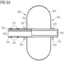
- Figure 5A further shows that the tube 200 can have different cross-sections along a longitudinal axis of the tube 200.
- the tube 200 may be formed between the opening 250 and the distal end tip 210 with a cross-section having only the gastric lumen 230. This allows a smaller outer diameter of the distal end of the tube 200, creating more space in particular in an area where the empty retaining element is disposed when folded.
- the tube 200 may be provided with indication elements 240, such as symbols 241 or tick marks of a scale. Such symbols 241 are provided on a portion of the tube 200 facing towards the proximal end of the tube, i.e. a portion that will lie outside of the body of the patient when the gastrostomy device 100 is placed in the patient's body cavity.
- the indication elements 240 may be arranged circumferentially and/or in a longitudinal direction of the tube 200 at any desired distance. In a circumferential direction, the indication elements 240 can be uniformly distributed, such as three indication elements every 120° (not shown in Figure 5A ).
- the symbols 241 can be spaced apart from each other in the longitudinal direction of the tube 200 by a predetermined distance.
- symbols 241 can be provided at equal intervals, such as 0.5 cm, 1 cm, 1.5cm, or any other distance required to form a scale indicating a distance to the retaining element 300 and, in particular, a distance to the surface 340 of the retaining element 300 abutting the stomach wall.
- the symbols 241 may surround the tube 200 entirely (forming rings on a surface of the tube 200 as illustrated in Figure 5A ) or may be subdivided in a circumferential direction.
- the indication elements 240 can be printed onto the surface of the tube 200 or may be integrated into the tube wall of tube 200.
- the retaining element 300 in an inflated state, can have a substantially ellipsoidal form. It is to be understood that the retaining element 300 does not need to have a perfectly symmetrical ellipsoidal form.
- the retaining element 300 may comprise one or more flat or plane surfaces 340, 345. It is particularly advantageous if a surface that will abut against the stomach wall of the patient has a flat or plane portion 340, since this provides good retaining properties. The retaining properties can be enhanced, if the flat or plane portion 340 is disposed substantially perpendicular to a longitudinal axis of the tube 200.
- the flat or plane surface 340 of Figure 5A may be bent inwardly, i.e. towards a center of the retaining element 300. This can be achieved by moving the proximal tubular extension 330 closer to the distal end of the tube 200 before adhering the proximal tubular extension 330 to the tube 200.
- the retaining element 300 may be fabricated as having a bulge that is maintained due to the form durability of the PUR- and PA-layers of the retaining element 300, where the proximal tubular extension 330 lies closer to a center of the retaining element 300.
- the retaining element 300 can be provided with a bulgy form on the opposite (distal) side, i.e. at surface 345.
- the distal tubular extension 320 may be adhered to the tube 200 resulting in the bulgy form of the retaining element 300 and/or the retaining element 300 may be fabricated with such bulgy form.
- the retaining element 300 can be provided with a flat or plane surface 345 on its distal side and the distal tubular extension 320 is brought closer to the proximal end of the tube 200 before adhering the distal tubular extension 320 to the tube 200.
- the flat or plane surface 345 can protrude further to a distal side of the gastrostomy device 100 than the distal end tip 210 of the tube 200.
- Such form of the retaining element 300 is illustrated in Figure 5C . This allows providing the distal end tip 210 closer to the center of the retaining element 300.
- distal side surface 345 of the retaining element 300 is not limited to the form illustrated in Figure 5C .
- the flat or plane surface 345 can instead be flush with the distal end tip 210 of the tube 200.
- the proximal side (surface 340) of the retaining element 300 can be formed corresponding to the distal side (surface 345) of the retaining element 300.
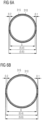
- a double layer tube may be formed as illustrated in Figures 6A and 6B .
- a double layer tube can be fabricated by coextrusion of PUR forming an inner layer 310 of the tube and PA forming an outer layer 315 of the tube.
- Figure 6A shows an exemplary tube having an outer diameter of approximately 5.6 mm and an inner diameter of approximately 5 mm.
- the thickness of the inner PUR-layer 310 can be between 0.1 mm and 0.4 mm, preferably 0.2 mm, and the thickness of the outer PA-layer 315 can be between 0.05 mm to 0.2 mm, preferably 0.1 mm.
- Such tube can be used to form a retaining element 300 that fits onto (can be coupled to) a tube 200 of size CH 10.
- the double layer tube may have an outer diameter of approximately 6.6 mm and an inner diameter of approximately 6 mm.
- the thickness of the inner PUR-layer 310 can be between 0.1 mm and 0.4 mm, preferably 0.2 mm, and the thickness of the outer PA-layer 315 can be between 0.05 mm to 0.2 mm, preferably 0.1 mm.
- Such tube can be used to form a retaining element 300 that fits onto (can be coupled to) a tube 200 of size CH 14.
- Such double layer tube is then expanded or widened to take the form of the retaining element 300, as shown in Figure 7 .
- the double-layered tube can be elongated or stretch formed before widening.
- the retaining element 300 can be taken out of a mold or tool. Any remaining parts of the double layer tube at one or both ends of the retaining element 300 can be cut to a desired length, thereby providing the proximal tubular extension 330 and/or the distal tubular extension 320.
- elongating the diameter of the double-layered tube decreases.
- varying diameters of the double-layer tube can be achieved.
- This allows forming tubular extensions 320, 330 that fit onto different portions of tube 200, such as portions 220, 225 ( Figure 5A ) having different diameters.
- both tubular extensions 320, 330 can have the same inner diameter, so that they fit onto a tube 200 having a continuous outer diameter.
- elongating the double-layered tube allows fabricating retaining elements 300 for tubes 200 of different sizes, e.g. CH 8 to CH 12, from the same double-layered tube, such as the double-layered tube illustrated in Figure 6A .
- the double-layered tube illustrated in Figure 6B may be used to fabricate retaining elements 300 for tubes 200 of sizes between CH 12 and CH 20. It is to be understood that a specific double-layered tube (having a specific diameter) can be employed only for a retaining element 300 for a certain tube size.
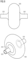
- Figure 8 schematically shows a side view and a perspective view of a retaining element 300 thus formed. Only one flat or plane surface 345 of the retaining element 300 is visible. It is to be understood that the retaining element can also be fabricated without a flat or plane surface.
- Figures 9A and 9B show cross-sections of gastrostomy tubes 200 of sizes CH10 and CH14, respectively.
- an outer diameter of the tube 200 can be approximately 3 mm and an inner diameter can be approximately 2 mm.
- the tube wall 245 thus formed creates a gastric lumen 230.
- a retainer lumen 235 Within the tube wall 245 can be a retainer lumen 235. Both lumens 230, 235 extend in a longitudinal direction of the tube 200, wherein the gastric lumen 230 extends to a distal end tip 210 of the tube 200 and the retainer lumen 235 is in fluid communication with an interior space of the retaining element 300. Such fluid communication can be achieved by an opening (not shown in Figure 9A ) through the tube wall 245 into the retainer lumen 235 (from an exterior side of the tube 200).
- the retainer lumen 235 can have a cross-section forming an ellipse.
- Such ellipse may have a minor axis that aligns with a radially direction of a cross-section of the tube 200, as shown in Figure 9A .
- the minor axis of the ellipse may have a length of approximately 0.4 mm, and a major axis of the ellipse may have a length of approximately 0.6 mm.
- the center of the ellipse may be about 1.1 mm from the center of the cross-section of the tube 200.
- the cross-section of the gastric lumen 230 has an indent.
- This indent may be formed by two curved sections moving towards the center of the tube 200, each having a radius of about 0.2 mm and an intermediate section with an opposite curvature with a radius of approximately 0.45 mm.
- This intermediate section can be substantially parallel to the corresponding part of the ellipse of the retainer lumen 235. Therefore, the indent into the gastric lumen 230, i.e. the interior surface of the tube wall 245 at the most indenting position, may be spaced apart from the center of the tube 200 by approximately 0.7 mm.
- an outer diameter of the (CH14) tube 200 can be approximately 4.2 mm and an inner diameter of approximately 3 mm.
- the cross-section of the gastric lumen 230 has an indent.
- This indent may be formed by two curved sections moving towards the center of the tube 200, each having a radius of about 0.3 mm and an intermediate section with an opposite curvature of a radius of approximately 0.65 mm being substantially parallel to the corresponding part of the ellipse of the retainer lumen 235. Therefore, the indent into the gastric lumen 230 may be closer to the center of the tube 200 than the remaining interior surface of the tube wall 245.
- indication elements 240 may be integrated into the tube wall 245.
- Figure 9B depicts indication elements 240 in the form of markers 242 may be arranged in a circumferential direction.
- the markers 242 can be uniformly distributed, such as three markers 242 every 120°.
- the markers 242 can have an approximately rectangular or elliptical cross-section having dimensions of approximately 0.8 mm and 0.3 mm.
- the distance between a marker 242 and an exterior surface of the tube wall 245 may be about 0.08 mm, while a distance between the marker 242 and an interior surface of the tube wall 245 (the surface of the gastric lumen 230) may be about 0.04 mm.
- the markers 242 may extend over the entire length of the tube 200 (in a longitudinal direction of the tube 200).
- symbols 241 can also be printed onto an exterior surface of the tube wall 245.
Landscapes
- Health & Medical Sciences (AREA)
- Life Sciences & Earth Sciences (AREA)
- Animal Behavior & Ethology (AREA)
- General Health & Medical Sciences (AREA)
- Public Health (AREA)
- Veterinary Medicine (AREA)
- Gastroenterology & Hepatology (AREA)
- Media Introduction/Drainage Providing Device (AREA)
Claims (14)
- Dispositif de gastrostomie (100), comprenant:un tube de gastrotomie (200); etun élément de retenue gonflable (300) accouplé au tube (200) au niveau d'une extrémité distale (205) du tube (200) ou proche de cette dernièrecaractérisé en ce que
l'élément de retenue (300) comprend une couche interne (310) constituée de polyuréthanne, PUR, et une couche externe (315) constituée de polyamide, PA. - Dispositif de gastrostomie (100) selon la revendication 1, dans lequel une partie (320, 330) de la couche interne de l'élément de retenue (330) est accouplée à une partie (220, 225) du tube (200).
- Dispositif de gastrostomie (100) selon la revendication 1 ou 2, dans lequel l'élément de retenue (300) est accouplé au tube (200) au niveau de deux parties (220, 225) du tube (200) espacées l'une de l'autre.
- Dispositif de gastrostomie (100) selon l'une quelconque des revendications 1 à 3, dans lequel l'élément de retenue (300) comprend au moins une extension tubulaire (320, 330) ayant une section transversale conçue pour protéger coaxialement le tube (200).
- Dispositif de gastrostomie (100) selon la revendication 4, dans lequel la couche externe (315) constituée de polyamide s'étend au moins partiellement sur l'au moins une extension tubulaire (320, 330).
- Dispositif de gastrostomie (100) selon l'une quelconque des revendications 1 à 5, dans lequel l'élément de retenue (300), lorsqu'il est gonflé, a une forme sensiblement ellipsoïdale.
- Dispositif de gastrostomie (100) selon l'une quelconque des revendications 1 à 6, dans lequel l'élément de retenue (300) a une partie plate (340) sensiblement perpendiculaire à un axe longitudinal du tube (200).
- Dispositif de gastrostomie (100) selon l'une quelconque des revendications 1 à 7, dans lequel une surface de l'élément de retenue (300), lorsqu'il est vide, a une zone sensiblement égale à une zone de la surface de l'élément de retenue (300), lorsqu'il est gonflé.
- Dispositif de gastrostomie (100) selon l'une quelconque des revendications 1 à 8, dans lequel le dispositif de gastrotomie (100) comprend en outre:
une gaine de protection (610) protégeant l'élément de retenue (300) lorsqu'il est vide, dans lequel l'élément de retenue (300), lorsqu'il est vide, est plié autour du tube (200). - Dispositif de gastrostomie (100) selon l'une quelconque des revendications 1 à 9, dans lequel le tube (200) comprend une lumière gastrique (230) s'étendant dans une direction longitudinale du tube (200) et une lumière de retenue (235) s'étendant dans une direction longitudinale du tube (200), dans lequel la lumière de retenue (235) est en communication fluidique avec un espace intérieur de l'élément de retenue (300), et dans lequel la lumière gastrique (230) s'étend vers une pointe d'extrémité distale (210) du tube (200) et est conçue pour laisser passer les aliments et/ou des médicaments et/ou du gaz.
- Dispositif de gastrostomie (100) selon la revendication 10, dans lequel la lumière de retenue (235) a une section transversale formant une ellipse, dans lequel un axe mineur de l'ellipse s'aligne avec une direction radiale d'une section transversale du tube (200).
- Dispositif de gastrostomie (100) selon l'une quelconque des revendications 1 à 11, dans lequel le tube (200) comprend des éléments d'indication (240) disposés circonférentiellement et/ou le long d'une direction longitudinale du tube (200).
- Dispositif de gastrostomie (100) selon la revendication 12, dans lequel au moins certains des éléments d'indication (240) sont visibles depuis l'extérieur du tube (200), et/ou dans lequel au moins certains éléments d'indication (240) sont intégrés dans une paroi (245) du tube (200), et/ou dans lequel au moins certains des éléments d'indication (240) comprennent un agent de contraste.
- Dispositif de gastrostomie (100) selon l'une quelconque des revendications 1 à 13, dans lequel au moins une partie du tube (200) est constituée de polyuréthanne, PUR.
Applications Claiming Priority (1)
| Application Number | Priority Date | Filing Date | Title |
|---|---|---|---|
| PCT/IB2017/000351 WO2018150219A1 (fr) | 2017-02-16 | 2017-02-16 | Dispositif de gastrostomie pourvu d'un élément de retenue amélioré |
Publications (2)
| Publication Number | Publication Date |
|---|---|
| EP3582744A1 EP3582744A1 (fr) | 2019-12-25 |
| EP3582744B1 true EP3582744B1 (fr) | 2023-05-24 |
Family
ID=58638898
Family Applications (1)
| Application Number | Title | Priority Date | Filing Date |
|---|---|---|---|
| EP17719902.3A Active EP3582744B1 (fr) | 2017-02-16 | 2017-02-16 | Dispositif de gastrostomie pourvu d'un élément de retenue amélioré |
Country Status (5)
| Country | Link |
|---|---|
| US (1) | US20200000681A1 (fr) |
| EP (1) | EP3582744B1 (fr) |
| CN (1) | CN110536671A (fr) |
| BR (1) | BR112019016907A2 (fr) |
| WO (1) | WO2018150219A1 (fr) |
Families Citing this family (5)
| Publication number | Priority date | Publication date | Assignee | Title |
|---|---|---|---|---|
| US20210298730A1 (en) * | 2020-03-30 | 2021-09-30 | Medtronic, Inc. | 3d printed splines on medical devices and methods to manufacture the same |
| EP4568636A2 (fr) | 2022-08-12 | 2025-06-18 | Luminoah, Inc. | Système de distribution de fluide habitronique |
| USD1033628S1 (en) | 2022-08-12 | 2024-07-02 | Luminoah, Inc. | Fluid delivery module |
| USD1029236S1 (en) | 2022-08-12 | 2024-05-28 | Luminoah, Inc. | Fluid pouch assembly |
| USD1029235S1 (en) | 2022-08-12 | 2024-05-28 | Luminoah, Inc. | Fluid delivery system |
Family Cites Families (16)
| Publication number | Priority date | Publication date | Assignee | Title |
|---|---|---|---|---|
| US5447497A (en) * | 1992-08-06 | 1995-09-05 | Scimed Life Systems, Inc | Balloon catheter having nonlinear compliance curve and method of using |
| EP1023913B1 (fr) * | 1997-10-08 | 2004-12-29 | Kaneka Corporation | Catheter a ballonnet et procede de fabrication |
| DE10131152B4 (de) * | 2001-04-30 | 2004-05-27 | Nutricia Healthcare S.A. | Medizinisches Ballon-Button-System |
| DE20303982U1 (de) * | 2003-03-13 | 2003-05-15 | REHAU AG + Co., 95111 Rehau | Katheter mit verbesserten Gleiteigenschaften |
| JP4988725B2 (ja) * | 2005-06-06 | 2012-08-01 | シー・アール・バード・インコーポレーテッド | バルーンチップを含む供給装置および製造方法 |
| US8307830B2 (en) * | 2006-09-29 | 2012-11-13 | Nellcor Puritan Bennett Llc | Endotracheal cuff and technique for using the same |
| WO2008051452A2 (fr) * | 2006-10-20 | 2008-05-02 | Boston Scientific Scimed, Inc. | Système de cathéter médical avec traverse de ballonnet |
| CA2709783C (fr) * | 2007-12-18 | 2014-08-12 | Sumitomo Bakelite Co., Ltd. | Tube guide avec ballonet pour ponction |
| US9211234B2 (en) * | 2010-09-27 | 2015-12-15 | Avent, Inc. | Configurable percutaneous endoscopic gastrostomy tube |
| US8177742B1 (en) * | 2010-12-23 | 2012-05-15 | Kimberly-Clark Wordwide, Inc. | Inflatable retention system for an enteral feeding device |
| US8632492B2 (en) * | 2011-01-31 | 2014-01-21 | Rebecca DeLegge | Enteral feeding tube and housing |
| JP5873281B2 (ja) * | 2011-09-29 | 2016-03-01 | 日本コヴィディエン株式会社 | 瘻孔カテーテル |
| CN103467878A (zh) * | 2013-08-12 | 2013-12-25 | 北京伏尔特技术有限公司 | 一种医用管材 |
| CN103656838A (zh) * | 2013-12-31 | 2014-03-26 | 易生科技(北京)有限公司 | 一种特殊球囊结构的导管 |
| CN104027883B (zh) * | 2014-06-30 | 2016-03-23 | 上海凯利泰医疗科技股份有限公司 | 一种可控弯的鼻腔专用球囊导管 |
| CN106178231A (zh) * | 2016-08-03 | 2016-12-07 | 武汉福脉医疗科技有限公司 | 医用双层耐高压球囊及其制备方法 |
-
2017
- 2017-02-16 EP EP17719902.3A patent/EP3582744B1/fr active Active
- 2017-02-16 US US16/486,228 patent/US20200000681A1/en not_active Abandoned
- 2017-02-16 WO PCT/IB2017/000351 patent/WO2018150219A1/fr not_active Ceased
- 2017-02-16 BR BR112019016907A patent/BR112019016907A2/pt not_active Application Discontinuation
- 2017-02-16 CN CN201780086638.3A patent/CN110536671A/zh active Pending
Also Published As
| Publication number | Publication date |
|---|---|
| BR112019016907A2 (pt) | 2020-04-14 |
| CN110536671A (zh) | 2019-12-03 |
| EP3582744A1 (fr) | 2019-12-25 |
| US20200000681A1 (en) | 2020-01-02 |
| WO2018150219A1 (fr) | 2018-08-23 |
Similar Documents
| Publication | Publication Date | Title |
|---|---|---|
| EP3582744B1 (fr) | Dispositif de gastrostomie pourvu d'un élément de retenue amélioré | |
| JP4527058B2 (ja) | 穿刺用バルーン | |
| US8486100B2 (en) | Guide tube having balloons for puncture | |
| EP1913926B1 (fr) | Système de catheter | |
| ES2302827T3 (es) | Procedimiento de fabricacion de cateter y cateter. | |
| US8518020B2 (en) | Safety urinary catheter | |
| JP2002360702A (ja) | カテーテルの製造方法およびそのカテーテル | |
| GB2559883A (en) | Urinary catheter | |
| US10561828B2 (en) | Treatment tool for endoscope | |
| US20150209239A1 (en) | Nasogastric tube | |
| US10653545B2 (en) | Sleeve tube and method of use | |
| MX2009002154A (es) | Cateter urinario interno con superficie de sellado prolongada. | |
| KR20190002514A (ko) | 커프붙이 튜브 | |
| US9999412B2 (en) | Fistula management device and method | |
| JP2006340914A (ja) | バルーンカテーテル | |
| RU2635652C2 (ru) | Усиленная конструкция концевого участка питающей трубки | |
| CA3073943A1 (fr) | Tube de manchon et procede d'utilisation | |
| WO2017201641A1 (fr) | Dispositif de masque laryngé | |
| JP7160633B2 (ja) | カテーテル | |
| US20150342834A1 (en) | Gastrostomy device with controlled shape silicone balloon | |
| WO2017201645A1 (fr) | Dispositif de masque laryngé |
Legal Events
| Date | Code | Title | Description |
|---|---|---|---|
| STAA | Information on the status of an ep patent application or granted ep patent |
Free format text: STATUS: UNKNOWN |
|
| STAA | Information on the status of an ep patent application or granted ep patent |
Free format text: STATUS: THE INTERNATIONAL PUBLICATION HAS BEEN MADE |
|
| PUAI | Public reference made under article 153(3) epc to a published international application that has entered the european phase |
Free format text: ORIGINAL CODE: 0009012 |
|
| STAA | Information on the status of an ep patent application or granted ep patent |
Free format text: STATUS: REQUEST FOR EXAMINATION WAS MADE |
|
| 17P | Request for examination filed |
Effective date: 20190916 |
|
| AK | Designated contracting states |
Kind code of ref document: A1 Designated state(s): AL AT BE BG CH CY CZ DE DK EE ES FI FR GB GR HR HU IE IS IT LI LT LU LV MC MK MT NL NO PL PT RO RS SE SI SK SM TR |
|
| AX | Request for extension of the european patent |
Extension state: BA ME |
|
| DAV | Request for validation of the european patent (deleted) | ||
| DAX | Request for extension of the european patent (deleted) | ||
| STAA | Information on the status of an ep patent application or granted ep patent |
Free format text: STATUS: EXAMINATION IS IN PROGRESS |
|
| 17Q | First examination report despatched |
Effective date: 20201201 |
|
| GRAP | Despatch of communication of intention to grant a patent |
Free format text: ORIGINAL CODE: EPIDOSNIGR1 |
|
| STAA | Information on the status of an ep patent application or granted ep patent |
Free format text: STATUS: GRANT OF PATENT IS INTENDED |
|
| INTG | Intention to grant announced |
Effective date: 20221220 |
|
| GRAS | Grant fee paid |
Free format text: ORIGINAL CODE: EPIDOSNIGR3 |
|
| GRAA | (expected) grant |
Free format text: ORIGINAL CODE: 0009210 |
|
| STAA | Information on the status of an ep patent application or granted ep patent |
Free format text: STATUS: THE PATENT HAS BEEN GRANTED |
|
| AK | Designated contracting states |
Kind code of ref document: B1 Designated state(s): AL AT BE BG CH CY CZ DE DK EE ES FI FR GB GR HR HU IE IS IT LI LT LU LV MC MK MT NL NO PL PT RO RS SE SI SK SM TR |
|
| REG | Reference to a national code |
Ref country code: GB Ref legal event code: FG4D |
|
| REG | Reference to a national code |
Ref country code: CH Ref legal event code: EP |
|
| REG | Reference to a national code |
Ref country code: DE Ref legal event code: R096 Ref document number: 602017068983 Country of ref document: DE |
|
| REG | Reference to a national code |
Ref country code: AT Ref legal event code: REF Ref document number: 1569107 Country of ref document: AT Kind code of ref document: T Effective date: 20230615 |
|
| REG | Reference to a national code |
Ref country code: IE Ref legal event code: FG4D |
|
| REG | Reference to a national code |
Ref country code: NL Ref legal event code: FP |
|
| REG | Reference to a national code |
Ref country code: LT Ref legal event code: MG9D |
|
| REG | Reference to a national code |
Ref country code: AT Ref legal event code: MK05 Ref document number: 1569107 Country of ref document: AT Kind code of ref document: T Effective date: 20230524 |
|
| PG25 | Lapsed in a contracting state [announced via postgrant information from national office to epo] |
Ref country code: SE Free format text: LAPSE BECAUSE OF FAILURE TO SUBMIT A TRANSLATION OF THE DESCRIPTION OR TO PAY THE FEE WITHIN THE PRESCRIBED TIME-LIMIT Effective date: 20230524 Ref country code: PT Free format text: LAPSE BECAUSE OF FAILURE TO SUBMIT A TRANSLATION OF THE DESCRIPTION OR TO PAY THE FEE WITHIN THE PRESCRIBED TIME-LIMIT Effective date: 20230925 Ref country code: NO Free format text: LAPSE BECAUSE OF FAILURE TO SUBMIT A TRANSLATION OF THE DESCRIPTION OR TO PAY THE FEE WITHIN THE PRESCRIBED TIME-LIMIT Effective date: 20230824 Ref country code: ES Free format text: LAPSE BECAUSE OF FAILURE TO SUBMIT A TRANSLATION OF THE DESCRIPTION OR TO PAY THE FEE WITHIN THE PRESCRIBED TIME-LIMIT Effective date: 20230524 Ref country code: AT Free format text: LAPSE BECAUSE OF FAILURE TO SUBMIT A TRANSLATION OF THE DESCRIPTION OR TO PAY THE FEE WITHIN THE PRESCRIBED TIME-LIMIT Effective date: 20230524 |
|
| PG25 | Lapsed in a contracting state [announced via postgrant information from national office to epo] |
Ref country code: RS Free format text: LAPSE BECAUSE OF FAILURE TO SUBMIT A TRANSLATION OF THE DESCRIPTION OR TO PAY THE FEE WITHIN THE PRESCRIBED TIME-LIMIT Effective date: 20230524 Ref country code: PL Free format text: LAPSE BECAUSE OF FAILURE TO SUBMIT A TRANSLATION OF THE DESCRIPTION OR TO PAY THE FEE WITHIN THE PRESCRIBED TIME-LIMIT Effective date: 20230524 Ref country code: LV Free format text: LAPSE BECAUSE OF FAILURE TO SUBMIT A TRANSLATION OF THE DESCRIPTION OR TO PAY THE FEE WITHIN THE PRESCRIBED TIME-LIMIT Effective date: 20230524 Ref country code: LT Free format text: LAPSE BECAUSE OF FAILURE TO SUBMIT A TRANSLATION OF THE DESCRIPTION OR TO PAY THE FEE WITHIN THE PRESCRIBED TIME-LIMIT Effective date: 20230524 Ref country code: IS Free format text: LAPSE BECAUSE OF FAILURE TO SUBMIT A TRANSLATION OF THE DESCRIPTION OR TO PAY THE FEE WITHIN THE PRESCRIBED TIME-LIMIT Effective date: 20230924 Ref country code: HR Free format text: LAPSE BECAUSE OF FAILURE TO SUBMIT A TRANSLATION OF THE DESCRIPTION OR TO PAY THE FEE WITHIN THE PRESCRIBED TIME-LIMIT Effective date: 20230524 Ref country code: GR Free format text: LAPSE BECAUSE OF FAILURE TO SUBMIT A TRANSLATION OF THE DESCRIPTION OR TO PAY THE FEE WITHIN THE PRESCRIBED TIME-LIMIT Effective date: 20230825 |
|
| PG25 | Lapsed in a contracting state [announced via postgrant information from national office to epo] |
Ref country code: FI Free format text: LAPSE BECAUSE OF FAILURE TO SUBMIT A TRANSLATION OF THE DESCRIPTION OR TO PAY THE FEE WITHIN THE PRESCRIBED TIME-LIMIT Effective date: 20230524 |
|
| PG25 | Lapsed in a contracting state [announced via postgrant information from national office to epo] |
Ref country code: SK Free format text: LAPSE BECAUSE OF FAILURE TO SUBMIT A TRANSLATION OF THE DESCRIPTION OR TO PAY THE FEE WITHIN THE PRESCRIBED TIME-LIMIT Effective date: 20230524 |
|
| PG25 | Lapsed in a contracting state [announced via postgrant information from national office to epo] |
Ref country code: SM Free format text: LAPSE BECAUSE OF FAILURE TO SUBMIT A TRANSLATION OF THE DESCRIPTION OR TO PAY THE FEE WITHIN THE PRESCRIBED TIME-LIMIT Effective date: 20230524 Ref country code: SK Free format text: LAPSE BECAUSE OF FAILURE TO SUBMIT A TRANSLATION OF THE DESCRIPTION OR TO PAY THE FEE WITHIN THE PRESCRIBED TIME-LIMIT Effective date: 20230524 Ref country code: RO Free format text: LAPSE BECAUSE OF FAILURE TO SUBMIT A TRANSLATION OF THE DESCRIPTION OR TO PAY THE FEE WITHIN THE PRESCRIBED TIME-LIMIT Effective date: 20230524 Ref country code: EE Free format text: LAPSE BECAUSE OF FAILURE TO SUBMIT A TRANSLATION OF THE DESCRIPTION OR TO PAY THE FEE WITHIN THE PRESCRIBED TIME-LIMIT Effective date: 20230524 Ref country code: DK Free format text: LAPSE BECAUSE OF FAILURE TO SUBMIT A TRANSLATION OF THE DESCRIPTION OR TO PAY THE FEE WITHIN THE PRESCRIBED TIME-LIMIT Effective date: 20230524 Ref country code: CZ Free format text: LAPSE BECAUSE OF FAILURE TO SUBMIT A TRANSLATION OF THE DESCRIPTION OR TO PAY THE FEE WITHIN THE PRESCRIBED TIME-LIMIT Effective date: 20230524 |
|
| REG | Reference to a national code |
Ref country code: DE Ref legal event code: R097 Ref document number: 602017068983 Country of ref document: DE |
|
| PLBE | No opposition filed within time limit |
Free format text: ORIGINAL CODE: 0009261 |
|
| STAA | Information on the status of an ep patent application or granted ep patent |
Free format text: STATUS: NO OPPOSITION FILED WITHIN TIME LIMIT |
|
| 26N | No opposition filed |
Effective date: 20240227 |
|
| PG25 | Lapsed in a contracting state [announced via postgrant information from national office to epo] |
Ref country code: SI Free format text: LAPSE BECAUSE OF FAILURE TO SUBMIT A TRANSLATION OF THE DESCRIPTION OR TO PAY THE FEE WITHIN THE PRESCRIBED TIME-LIMIT Effective date: 20230524 |
|
| PG25 | Lapsed in a contracting state [announced via postgrant information from national office to epo] |
Ref country code: SI Free format text: LAPSE BECAUSE OF FAILURE TO SUBMIT A TRANSLATION OF THE DESCRIPTION OR TO PAY THE FEE WITHIN THE PRESCRIBED TIME-LIMIT Effective date: 20230524 Ref country code: IT Free format text: LAPSE BECAUSE OF FAILURE TO SUBMIT A TRANSLATION OF THE DESCRIPTION OR TO PAY THE FEE WITHIN THE PRESCRIBED TIME-LIMIT Effective date: 20230524 |
|
| PG25 | Lapsed in a contracting state [announced via postgrant information from national office to epo] |
Ref country code: MC Free format text: LAPSE BECAUSE OF FAILURE TO SUBMIT A TRANSLATION OF THE DESCRIPTION OR TO PAY THE FEE WITHIN THE PRESCRIBED TIME-LIMIT Effective date: 20230524 |
|
| PG25 | Lapsed in a contracting state [announced via postgrant information from national office to epo] |
Ref country code: LU Free format text: LAPSE BECAUSE OF NON-PAYMENT OF DUE FEES Effective date: 20240216 |
|
| PG25 | Lapsed in a contracting state [announced via postgrant information from national office to epo] |
Ref country code: LU Free format text: LAPSE BECAUSE OF NON-PAYMENT OF DUE FEES Effective date: 20240216 |
|
| PG25 | Lapsed in a contracting state [announced via postgrant information from national office to epo] |
Ref country code: BG Free format text: LAPSE BECAUSE OF FAILURE TO SUBMIT A TRANSLATION OF THE DESCRIPTION OR TO PAY THE FEE WITHIN THE PRESCRIBED TIME-LIMIT Effective date: 20230524 |
|
| PG25 | Lapsed in a contracting state [announced via postgrant information from national office to epo] |
Ref country code: BG Free format text: LAPSE BECAUSE OF FAILURE TO SUBMIT A TRANSLATION OF THE DESCRIPTION OR TO PAY THE FEE WITHIN THE PRESCRIBED TIME-LIMIT Effective date: 20230524 |
|
| REG | Reference to a national code |
Ref country code: BE Ref legal event code: MM Effective date: 20240229 |
|
| PG25 | Lapsed in a contracting state [announced via postgrant information from national office to epo] |
Ref country code: BE Free format text: LAPSE BECAUSE OF NON-PAYMENT OF DUE FEES Effective date: 20240229 |
|
| PG25 | Lapsed in a contracting state [announced via postgrant information from national office to epo] |
Ref country code: BE Free format text: LAPSE BECAUSE OF NON-PAYMENT OF DUE FEES Effective date: 20240229 |
|
| PG25 | Lapsed in a contracting state [announced via postgrant information from national office to epo] |
Ref country code: CY Free format text: LAPSE BECAUSE OF FAILURE TO SUBMIT A TRANSLATION OF THE DESCRIPTION OR TO PAY THE FEE WITHIN THE PRESCRIBED TIME-LIMIT; INVALID AB INITIO Effective date: 20170216 |
|
| PG25 | Lapsed in a contracting state [announced via postgrant information from national office to epo] |
Ref country code: HU Free format text: LAPSE BECAUSE OF FAILURE TO SUBMIT A TRANSLATION OF THE DESCRIPTION OR TO PAY THE FEE WITHIN THE PRESCRIBED TIME-LIMIT; INVALID AB INITIO Effective date: 20170216 |
|
| PG25 | Lapsed in a contracting state [announced via postgrant information from national office to epo] |
Ref country code: TR Free format text: LAPSE BECAUSE OF FAILURE TO SUBMIT A TRANSLATION OF THE DESCRIPTION OR TO PAY THE FEE WITHIN THE PRESCRIBED TIME-LIMIT Effective date: 20230524 |
|
| REG | Reference to a national code |
Ref country code: CH Ref legal event code: U11 Free format text: ST27 STATUS EVENT CODE: U-0-0-U10-U11 (AS PROVIDED BY THE NATIONAL OFFICE) Effective date: 20260301 |
|
| PGFP | Annual fee paid to national office [announced via postgrant information from national office to epo] |
Ref country code: NL Payment date: 20260218 Year of fee payment: 10 |
|
| PGFP | Annual fee paid to national office [announced via postgrant information from national office to epo] |
Ref country code: GB Payment date: 20260219 Year of fee payment: 10 |
|
| PGFP | Annual fee paid to national office [announced via postgrant information from national office to epo] |
Ref country code: DE Payment date: 20260217 Year of fee payment: 10 Ref country code: IE Payment date: 20260218 Year of fee payment: 10 |
|
| PGFP | Annual fee paid to national office [announced via postgrant information from national office to epo] |
Ref country code: FR Payment date: 20260223 Year of fee payment: 10 |
|
| PGFP | Annual fee paid to national office [announced via postgrant information from national office to epo] |
Ref country code: CH Payment date: 20260301 Year of fee payment: 10 |