EP3582873B1 - Séparateur de gouttes à faible encombrement en hauteur - Google Patents
Séparateur de gouttes à faible encombrement en hauteur Download PDFInfo
- Publication number
- EP3582873B1 EP3582873B1 EP18721260.0A EP18721260A EP3582873B1 EP 3582873 B1 EP3582873 B1 EP 3582873B1 EP 18721260 A EP18721260 A EP 18721260A EP 3582873 B1 EP3582873 B1 EP 3582873B1
- Authority
- EP
- European Patent Office
- Prior art keywords
- droplet separator
- retaining plates
- plates
- separator according
- droplet
- Prior art date
- Legal status (The legal status is an assumption and is not a legal conclusion. Google has not performed a legal analysis and makes no representation as to the accuracy of the status listed.)
- Active
Links
Images


Classifications
-
- B—PERFORMING OPERATIONS; TRANSPORTING
- B01—PHYSICAL OR CHEMICAL PROCESSES OR APPARATUS IN GENERAL
- B01D—SEPARATION
- B01D45/00—Separating dispersed particles from gases or vapours by gravity, inertia, or centrifugal forces
- B01D45/04—Separating dispersed particles from gases or vapours by gravity, inertia, or centrifugal forces by utilising inertia
- B01D45/08—Separating dispersed particles from gases or vapours by gravity, inertia, or centrifugal forces by utilising inertia by impingement against baffle separators
Definitions
- the present invention relates to a droplet separator for a vertical flow channel, in particular a flue gas desulfurization system, with a droplet separator layer arranged horizontally or continuously inclined on one side with respect to the vertical flow channel, with a plurality of lamellar droplet separator profiles arranged parallel to one another.
- Droplet separators for a vertical flow channel which have a droplet separator layer or several droplet separator layers, which can be, for example, a coarse separator and a downstream fine separator. These droplet separator layers are roof-shaped or V-shaped and are laterally supported either directly or via a corresponding support structure on carriers of the flow channel. Such a droplet separator is, for example, from DE 20 2007 001 942 U1 known.
- droplet separators have a support rod which extends from one carrier to the other carrier and which serves to arrange spray pipes for cleaning the droplet separator. It is also known to fix the tip of a roof-shaped droplet separator layer on such a support rod.
- droplet separators which have horizontally designed or arranged droplet separator layers which are mounted on various supporting beams which extend over the cross section of a flow channel. It is also from the DE 20 2011 109 332 U1 known to hang roof-shaped droplet separator layers on such support beams.
- Such a droplet separator arrangement is also, for example, from FIG WO 2005/107921 A1 known.
- the roof-shaped or V-shaped droplet separators mentioned at the outset have the advantage that, due to their roof-shaped or V-shaped inclined droplet separator layers, which usually have a relatively large angle of attack, they enable good drainage of the separated liquid or the cleaning liquid.
- this liquid is discharged laterally downwards from the top of the roof along the lamellar profiles.
- V-shaped separators the discharge is down to the middle.
- a disadvantage of such a trained separator is the fact that, due to the relatively large The angle of incidence of the droplet separator layers have a relatively large overall height.
- the DE 10 2005 061 780 A1 discloses a vertically traversed droplet separator with lamellar droplet separator profiles arranged horizontally and parallel to one another, which form an entire horizontal droplet separator layer.
- the lamellar separators have end walls running transversely to the lamellae and intermediate walls which are also arranged transversely.
- the separation device is held on the side of the support beam and has additional support rods.
- a reduction in the angle of attack in the case of the roof-shaped or V-shaped separator layers described above has the advantage of a lower overall height, but is associated with greater difficulties in terms of construction, since this creates high horizontal forces.
- the present invention is based on the object of creating a droplet separator of the specified type which, with a simple construction, is characterized by a particularly low overall height.
- the invention turns away from the previous roof-shaped or V-shaped construction of the separator layers and instead proposes a separator layer that is arranged horizontally or continuously inclined over the entire span, ie from carrier device to carrier device of the flow channel.
- a separator layer that is arranged horizontally or continuously inclined over the entire span, ie from carrier device to carrier device of the flow channel.
- intermediate supports are provided, the corresponding droplet separator layer having at least one intermediate support over its span.
- This intermediate support is formed by an intermediate wall, which carries the lamellar droplet separator profiles of the droplet separator layer, and by a holding plate on which the intermediate wall is supported or on which the intermediate wall is attached.
- the at least one holding plate is in turn mounted on a support rod which extends above or below the droplet separator layer from one carrier device to the other carrier device and forms the actual support element for the droplet separator layer. If the droplet separator layer is located above the support rod, the holding plate mounted on the support rod forms a corresponding support for the at least one partition of the separator layer. If the separator layer is arranged below the support rod, it depends the retaining plate on the support rod and forms the suspension for the partition wall of the separator layer.
- the two end walls of the separator layer are also carried by corresponding holding plates or are suspended from these, wherein the support rod can extend through the holding plates.
- this layer therefore has two end walls and at least one partition that carries the individual lamellar droplet separator profiles, as well as three retaining plates that are assigned to the two end walls and the at least one partition, and at least one support rod, which carries the supported or suspended retaining plates.
- the lamellar droplet separator profiles preferably extend through corresponding slots in the at least one partition.
- the at least one droplet separator layer can be arranged horizontally or continuously inclined on one side from end wall to end wall.
- the at least one droplet separator layer has at least one support over its entire span, relatively large spans can be bridged.
- the flow cross-section is indeed slightly narrowed, but this narrowing is shown according to the invention in FIG Taken because the advantages achieved by this arrangement predominate.
- the solution according to the invention is based on a novel principle for load transfer. While in the roof-shaped or V-shaped constructions mentioned at the beginning, the support rods provided there only have the task of storing corresponding spray pipes for the cleaning system, and which have no support function for the separator layer over the free cross-sectional area, the support rod provided in the invention takes all the loads the separator layer, which are transferred to the support rod via the corresponding retaining plates. As a result, the bearing rod is subjected to bending stress. In contrast, in the case of the roof-shaped or V-shaped constructions, the load is transferred directly to the carrier devices arranged on both sides of the flow channel.
- a particularly preferred embodiment of the droplet separator designed according to the invention is characterized in that it is designed in two stages and has a droplet separator layer arranged above and below the support rod.
- the droplet separator layer arranged below the support rod can be a coarse separator and the droplet separator layer arranged above the support rod can be a fine separator.
- the retaining plates extend from the upper edge regions of the end walls and partition walls of the lower separator layer to the lower edge regions of the end walls and partition walls of the upper separator layer and are connected to the end walls and Partitions connected to one another in a suitable manner.
- the support rod preferably extends through corresponding openings in the holding plates and therefore forms an essentially central bearing device for them.
- the holding plates are therefore subjected to pressure through the upper separator layer, with support on the support rod.
- the lower separator layer puts the holding plates under tension, with the support rod forming the corresponding bearing.
- the fastening of the retaining plates to the respective end walls and intermediate walls of the separator layers can in principle be carried out in any way, for example by screwing, welding, soldering, plugging together.
- the retaining plates can be screwed to the walls of the lower separator layer, while they can be connected to the walls of the upper separator layer via plug connections.
- plug connections have the advantage of simple assembly and disassembly.
- web plates that extend transversely and connect them are arranged between the holding plates.
- These multi wall sheets extend therefore parallel to the longitudinal direction of the support rod and are connected in a suitable manner to the adjacent retaining plates, for example also via plug connections, so that simple and quick assembly and disassembly is possible.
- the web plates are mounted with their lower edge or their upper edge on the support rod.
- the web plates are therefore preferably arranged on the support rod.
- the web plates are preferably provided below the support rod.
- corresponding web plates can be arranged both above and below the support rod.
- the retaining plates and / or web plates have reinforcing webs. These reinforcement bars also serve to stabilize the support system.
- the reinforcement webs are preferably connected to the retaining plates and / or web plates via plug connections, so that they can be removed quickly when the system is dismantled.
- the partition walls and / or end walls have sections which are extended upwards or downwards for storage purposes, in particular of spray pipes. These sections can therefore, for example, have corresponding recesses in which Spray pipes or other storage elements are arranged.
- the retaining plates and / or web plates can also have openings for the passage of spray pipes or bearing elements, etc.
- the retaining plates arranged on the end walls preferably have outwardly extending flanges for supporting the support rod.
- These flanges can be designed as angled flanges and thus have an end wall extending parallel to the holding plate. Appropriate supports for this end wall can be provided.
- the parts of the support system can be connected to one another via plug connections.
- the retaining plates can therefore be fixed with the partition walls, end walls, web plates and / or with reinforcement webs via plug connections.
- plug connections have the great advantage that quick and easy assembly and disassembly of the support system is possible, for example, in order to be able to carry out maintenance work on the separator layers.
- the provided droplet separator layer can be arranged horizontally or at an angle of inclination or angle of inclination, which is preferably small in order to achieve a low overall height of the overall system.
- a small angle of inclination compared to a horizontal position is advantageous, since this allows the liquid to be drained off easily.
- an angle of inclination comes between > 0 ° and ⁇ 20 ° for use.
- the layers can have different angles of inclination. For example, a horizontally arranged position can be combined with a position with an angle of inclination between 0 ° and 20 °, an angle of inclination of 15 ° representing a preferred embodiment.
- the droplet separator designed according to the invention preferably has feed pipes for a cleaning liquid which run parallel to the holding plates and from which nozzle pipes branch off parallel to the lamellar droplet separator profiles.
- These feed pipes preferably extend through openings in the web plates and are supported by them.
- two feed pipes are arranged within the space between the outer holding plates.
- Such feed pipes can, however, also be arranged outside the outer holding plates, for example be supported there on corresponding flanges.
- spray pipes branch off parallel to the lamellar droplet separator profiles. With these spray pipes, the corresponding droplet separator layers are cleaned in a known manner from below / or from above.
- a special embodiment is characterized in that the droplet separator has at least one feed pipe which is arranged below the lowermost droplet separator layer and is carried by a holder extending downward from the lowermost droplet separator layer will.
- This holder preferably extends parallel to the lamellar droplet separator profiles and has an opening which receives the feed pipe running at right angles thereto.
- the support rod is arranged with its two end sections in box-shaped projections on the outside of the outer retaining plates, these box-shaped projections supporting the droplet separator in the installed state on corresponding support devices of a flow channel, in particular a flue gas desulfurization system.
- All parts of the droplet separator construction described here, apart from the support rod, are preferably made of a suitable plastic.
- the support rod can, for example, be a plastic-coated steel beam.
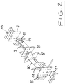
- the droplet separator shown is designed in two stages and designed for installation in a vertical flow channel of a flue gas desulfurization system.
- the droplet separator has a lower droplet separator layer 1 and an upper droplet separator layer 2, which are designed as coarse separators and fine separators and each consist of a large number of lamellar profiles arranged next to one another. These lamellar profiles are known and therefore do not need to be described in detail.
- the individual lamellar profiles 16 are welded to end walls 3, 4 which extend transversely to the lamellar profiles 16 and extend through the slots of two intermediate walls 5, 6.
- the lower droplet separator layer 1 is arranged at an angle of inclination of 10 °, while the upper droplet separator layer 2 has an angle of inclination of 15 ° to the horizontal.
- a special support structure is used for mounting the droplet separator on support devices of the flow channel, for example on its side walls.
- the main element of this support structure is a support rod 9 which transfers the corresponding load of the upper and lower droplet separator layers 1, 2 to the lateral support devices of the flow channel.
- This support rod 9 extends through a total of four holding plates 8, which extend transversely to the support rod 9 and are arranged in a vertical extension of the end walls 3, 4 and intermediate walls 5, 6 of the separator layers 1, 2.
- the retaining plates 8 each have an approximately central opening through which the support rod 9 extends so that the upper droplet separator layer 2 can be supported on the support rod 9 via the upper area of the retaining plates 8, while the other droplet separator layer 1 over the lower area of the retaining plates 8 is suspended from the support rod 9.
- the end walls 3 and intermediate walls 5 of the lower droplet separator layer 1 are screwed to the holding plates 8 in their upper edge area.
- the end walls 4 and intermediate walls 6 of the upper droplet separator layer 2 are connected with their lower edge regions to the holding plates 8 via suitable plug connections.
- web plates 10 are arranged above and below the support rod 9, which each extend between two retaining plates and connect them to one another. This can also be done by means of suitable plug connections. Furthermore, the holding plates 8 Stiffening webs 11 which are attached to the retaining plates by plug connections.
- an intermediate wall 5 has a downwardly extending section 7 which is provided with a suitable recess for receiving a nozzle pipe for cleaning the separator.
- Such spray pipes can also extend through suitable holes in the web plates 10, as shown for example at 14.
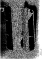
- Figure 3 shows the separator of the Figures 1 and 2 in the extended state of the two separator layers 1, 2 and the supporting structure arranged between them. Only the end walls 3 and intermediate walls 5 of the lower separator layer 1 are screwed to the holding plates 8 of the supporting structure, while all other connections are plug connections.
- one element has a hook that is guided through an opening in the other element.
- the web plate 10 has such a hook 12 on the end face, which is guided through a slot in the associated holding plate 8.
- a locking of the two elements with one another is then achieved by moving the web plate 10 downwards.
- the web plate 10 is raised, after which the hook 12 can be removed from the slot opening.
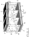
- Figure 4 shows an overall view of the two-stage separator with supporting structure, some spray pipes 15 being shown here in detail.
- FIG Figure 5 shows a further embodiment of a two-stage droplet separator. This differs from the embodiment of Figure 4 essentially only through the design of the spray system. While in the embodiment of Figure 4 a feed pipe 15 for the cleaning liquid for the spraying system is arranged on the outside of the holding plate 8 on the left in the figure, are in the embodiment of FIG Figure 5 two feed pipes 15 (not shown) are provided within the space between the outer holding plates 8. Here, too, the feed pipes 15 extend parallel to the holding plates 8 through corresponding openings 14 in the web plates 10. In this case, a web plate 10 is also arranged below the support rod 9 and a web plate 10 is arranged above the support rod. In the middle, ie between the two middle retaining plates 8, there is no web plate.
- spray pipes 20 branch off at right angles, which run parallel to the lamellar droplet separator profiles 16.
- the spray pipes 20 act on the upper and lower droplet separator layers 2, 1 with a corresponding one Cleaning liquid which is supplied via the supply pipes 15.
- the droplet separator has a further feed pipe 15 (also not shown) which is arranged below the lower droplet separator layer 1.
- This feed pipe 15 is carried by a holder 22 extending downward from the lower droplet separator layer 1.
- this holder 22 is designed as a triangular plate-shaped element which has an opening 21 for receiving the feed pipe 15.
- a spray pipe 20 branches off at right angles, with which the underside of the lower droplet separator layer 1 is sprayed.
- This nozzle 20 is carried by a further holder 23 extending downwards.
- the support rod 9 is mounted with its end sections on both sides in box-shaped lugs 24 which are arranged on the outer sides of the outer retaining plates 8. With these box-shaped extensions 24, the droplet separator is mounted in the installed state on corresponding support devices of a flow channel, in particular of a flue gas desulfurization system.
Landscapes
- Chemical & Material Sciences (AREA)
- Chemical Kinetics & Catalysis (AREA)
- Treating Waste Gases (AREA)
- Gas Separation By Absorption (AREA)
- Separating Particles In Gases By Inertia (AREA)
- Filtration Of Liquid (AREA)
Claims (14)
- Séparateur de gouttes pour un canal d'écoulement vertical, en particulier d'une installation de désulfurisation des gaz de fumée, avec une couche de séparateur de gouttes (1, 2) disposée horizontalement par rapport au canal d'écoulement vertical ou de façon inclinée en continu vers un côté, avec une pluralité de profilés de séparateur de gouttes à lamelles (16) disposés parallèlement les uns aux autres, lesquels sont pourvus de parois terminales (3, 4) s'étendant transversalement à ceux-ci et au moins une paroi intermédiaire (5, 6) s'étendant transversalement à ceux-ci,- une barre de support (9) disposée au-dessus ou en dessous de la couche de séparateur de gouttes (1, 2), laquelle est formée sur des dispositifs de support bilatéraux du canal d'écoulement vertical pour le montage côté extrémité, et- des plaques de maintien (8) disposées sur les parois terminales et intermédiaires (3, 4, 5, 6), approximativement dans le prolongement vertical de celles-ci, à travers lesquelles s'étend la barre de support (9) et lesquelles s'appuient sur celle-ci ou sont accrochées à celle-ci,dans lequel des plaques de traverse (10) s'étendant transversalement aux plaques de maintien (8) sont disposées entre celles-ci tout en les reliant et sont montées sur la barre de support (9) avec leur bord inférieur ou leur bord supérieur, etdans lequel les plaques de maintien (8) et/ou les plaques de traverse (10) possèdent des ouvertures (14) pour le passage de tuyaux de pulvérisation.
- Séparateur de gouttes selon la revendication 1, caractérisé en ce qu'il est conçu avec deux étages et présente des couches de séparateur de gouttes (1, 2) disposées au-dessus et en dessous de la barre de support (9).
- Séparateur de gouttes selon la revendication 1 ou 2, caractérisé en ce que les plaques de maintien (8) sont vissées avec les parois terminales (3) et les parois intermédiaires (5).
- Séparateur de gouttes selon l'une des revendications précédentes, caractérisé en ce que les plaques de maintien (8) et/ou les plaques de traverse (10) présentent des traverses de renforcement (11).
- Séparateur de gouttes selon l'une des revendications précédentes, caractérisé en ce que les parois intermédiaires (5) et/ou les parois terminales (3) présentent des sections (7) prolongées vers le haut ou vers le bas et destinées au montage, en particulier de tuyaux de pulvérisation.
- Séparateur de gouttes selon l'une des revendications précédentes, caractérisé en ce que les plaques de maintien (8) disposées sur les parois terminales (3, 4) possèdent des brides (13) s'étendant vers l'extérieur pour l'appui de la barre de support (9).
- Séparateur de gouttes selon l'une des revendications 4 à 6, caractérisé en ce que les plaques de maintien (8) sont reliées l'une à l'autre aux parois intermédiaires (5, 6), aux parois terminales (3, 4), aux plaques de traverse (10) et/ou aux traverses de renforcement (11) par des raccords enfichables.
- Séparateur de gouttes selon l'une des revendications 2 à 7, caractérisé en ce que les deux couches de séparateur de gouttes (1, 2) présentent des inclinaisons différentes.
- Séparateur de gouttes selon l'une des revendications précédentes, caractérisé en ce que la couche de séparateur de gouttes (1, 2) présente un angle d'inclinaison > 0° et ≤ 20°.
- Séparateur de gouttes selon l'une des revendications précédentes, caractérisé en ce que les profilés de séparateur de gouttes à lamelles s'étendent à travers des fentes dans l'au moins une paroi intermédiaire (5, 6).
- Séparateur de gouttes selon l'une des revendications précédentes, caractérisé en ce qu'il présente des tuyaux d'alimentation (15) s'étendant parallèlement aux plaques de maintien (8) pour un liquide de nettoyage, à partir desquels des tuyaux de pulvérisation (20) bifurquent parallèlement aux profilés de séparateur de gouttes à lamelles (16).
- Séparateur de gouttes selon la revendication 11, caractérisé en ce que deux tuyaux d'alimentation (15) sont disposés dans l'espace entre les plaques de maintien extérieures (8).
- Séparateur de gouttes selon la revendication 11, caractérisé en ce qu'il présente au moins un tuyau d'alimentation (21) disposé sous la couche de séparateur de gouttes la plus inférieure (1) et porté par une monture (22) s'étendant vers le bas à partir de la couche de séparateur de gouttes la plus inférieure (1).
- Séparateur de gouttes selon l'une des revendications précédentes, caractérisé en ce que la barre de support (9) est disposée avec ses deux sections d'extrémité dans des embouts en forme de boîtiers (24) sur les côtés extérieurs des plaques de maintien extérieures (8), lesquels servent au montage du séparateur de gouttes.
Priority Applications (1)
| Application Number | Priority Date | Filing Date | Title |
|---|---|---|---|
| PL18721260T PL3582873T3 (pl) | 2017-02-14 | 2018-02-10 | Odkraplacz o małej wysokości konstrukcyjnej |
Applications Claiming Priority (2)
| Application Number | Priority Date | Filing Date | Title |
|---|---|---|---|
| DE102017001415.9A DE102017001415A1 (de) | 2017-02-14 | 2017-02-14 | Tropfenabscheider mit geringer Bauhöhe |
| PCT/DE2018/000028 WO2018149432A1 (fr) | 2017-02-14 | 2018-02-10 | Séparateur de gouttes à faible encombrement en hauteur |
Publications (2)
| Publication Number | Publication Date |
|---|---|
| EP3582873A1 EP3582873A1 (fr) | 2019-12-25 |
| EP3582873B1 true EP3582873B1 (fr) | 2021-09-22 |
Family
ID=62091617
Family Applications (1)
| Application Number | Title | Priority Date | Filing Date |
|---|---|---|---|
| EP18721260.0A Active EP3582873B1 (fr) | 2017-02-14 | 2018-02-10 | Séparateur de gouttes à faible encombrement en hauteur |
Country Status (5)
| Country | Link |
|---|---|
| EP (1) | EP3582873B1 (fr) |
| CN (1) | CN110392602B (fr) |
| DE (1) | DE102017001415A1 (fr) |
| PL (1) | PL3582873T3 (fr) |
| WO (1) | WO2018149432A1 (fr) |
Families Citing this family (1)
| Publication number | Priority date | Publication date | Assignee | Title |
|---|---|---|---|---|
| DE102018133150A1 (de) * | 2018-12-20 | 2020-06-25 | Rvt Process Equipment Gmbh | Tropfenabscheider mit neuer Verbindungsstruktur |
Family Cites Families (10)
| Publication number | Priority date | Publication date | Assignee | Title |
|---|---|---|---|---|
| DE202004021688U1 (de) * | 2004-05-04 | 2010-04-22 | Munters Euroform Gmbh | Tropfenabscheideranordnung |
| DE102005061780A1 (de) * | 2005-12-23 | 2007-06-28 | Rea Plastik Tech Gmbh | Stützkonstruktion für die Bedüsungsanlage eines Tropfenabscheidersystem |
| DE102006011185A1 (de) * | 2006-03-10 | 2007-09-13 | Munters Euroform Gmbh | Tropfenabscheideranordnung |
| DE102006011152B4 (de) * | 2006-03-10 | 2016-12-15 | Munters Euroform Gmbh | Tropfenabscheideranordnung |
| DE202007001942U1 (de) | 2007-02-10 | 2007-08-16 | Munters Euroform Gmbh | Tropfenabscheider für Gaswäscher |
| MX337339B (es) * | 2010-09-30 | 2016-02-26 | Sulzer Chemtech Ag | Separador de gotas. |
| DE202011106925U1 (de) * | 2011-10-18 | 2011-12-13 | Munters Euroform Gmbh | Tropfenabscheiderpaket mit verrastbaren Halteleisten |
| DE202011109332U1 (de) | 2011-12-21 | 2012-10-08 | Rea Plastik Tech Gmbh | Austauschtropfenabscheider in Dachform für einen sehr flachen Rauchgasentschwefelungsanlagenturm |
| CN204502709U (zh) * | 2015-01-24 | 2015-07-29 | 宏电建设集团有限公司 | 一种脱硫塔 |
| CN105983287A (zh) * | 2015-01-27 | 2016-10-05 | 德梅斯特(上海)环保科技有限公司 | 一种高效除尘除雾一体化系统 |
-
2017
- 2017-02-14 DE DE102017001415.9A patent/DE102017001415A1/de not_active Withdrawn
-
2018
- 2018-02-10 WO PCT/DE2018/000028 patent/WO2018149432A1/fr not_active Ceased
- 2018-02-10 PL PL18721260T patent/PL3582873T3/pl unknown
- 2018-02-10 EP EP18721260.0A patent/EP3582873B1/fr active Active
- 2018-02-10 CN CN201880011781.0A patent/CN110392602B/zh active Active
Also Published As
| Publication number | Publication date |
|---|---|
| CN110392602A (zh) | 2019-10-29 |
| EP3582873A1 (fr) | 2019-12-25 |
| DE102017001415A1 (de) | 2018-08-16 |
| PL3582873T3 (pl) | 2022-04-04 |
| WO2018149432A1 (fr) | 2018-08-23 |
| CN110392602B (zh) | 2022-01-04 |
Similar Documents
| Publication | Publication Date | Title |
|---|---|---|
| EP2090744B1 (fr) | Chariot de transport | |
| DE2642531A1 (de) | Fahrzeugkasten | |
| EP1742718B1 (fr) | Systeme de pare-gouttes | |
| EP2125150A1 (fr) | Dispositif de dépôt de gouttes pour dispositif de lavage de gaz | |
| EP1544377B1 (fr) | Element de coffrage pour murs courbes | |
| EP3140474B1 (fr) | Pompe à béton mobile | |
| WO2018149432A1 (fr) | Séparateur de gouttes à faible encombrement en hauteur | |
| DE202008012407U1 (de) | Freitragende Stahlhalle | |
| EP3650616A1 (fr) | Toit de protection contre les intempéries de textile tendu pourvu de bordure d'appui sur le textile | |
| EP3582874B1 (fr) | Séparateur de gouttes comprenant des liaisons par enfichage | |
| EP1545743B1 (fr) | Epurateur des gaz de fumees comportant une construction support destinee a des tubes de pulverisation | |
| WO2014111401A1 (fr) | Cadre d'appui à plateau grillagé pour une étagère | |
| DE202022105414U1 (de) | Tragkonstruktionsmontagesystem für Photovoltaik-Module | |
| EP1911502B1 (fr) | Arrangement de separateurs de gouttelettes | |
| AT526675B1 (de) | Fahrzeugunterstand | |
| DE102006011152B4 (de) | Tropfenabscheideranordnung | |
| DE102009001275B4 (de) | Regalsystem | |
| DE69004235T2 (de) | Viadukt für Eisenbahngleise. | |
| DE8411168U1 (de) | Haengegeruest fuer arbeiten an bruecken od.dgl. | |
| DE19640074C1 (de) | Waschturm für eine Rauchgasentschwefelungsanlage | |
| EP2250458B1 (fr) | Dispositif de refroidissement de retour d'eau de refroidissement | |
| DE29622980U1 (de) | Tragkonstruktion für Bedüsungsrohre bei Gaswäschern | |
| WO2025056609A1 (fr) | Dispositif pour accueillir une pièce et dispositif de découpe au laser ou au plasma | |
| DE29504642U1 (de) | Planierstange für Verkokungsöfen | |
| DE202006005371U1 (de) | Boden, insbesondere für Räume an Bord von Schiffen |
Legal Events
| Date | Code | Title | Description |
|---|---|---|---|
| STAA | Information on the status of an ep patent application or granted ep patent |
Free format text: STATUS: UNKNOWN |
|
| STAA | Information on the status of an ep patent application or granted ep patent |
Free format text: STATUS: THE INTERNATIONAL PUBLICATION HAS BEEN MADE |
|
| PUAI | Public reference made under article 153(3) epc to a published international application that has entered the european phase |
Free format text: ORIGINAL CODE: 0009012 |
|
| STAA | Information on the status of an ep patent application or granted ep patent |
Free format text: STATUS: REQUEST FOR EXAMINATION WAS MADE |
|
| 17P | Request for examination filed |
Effective date: 20190902 |
|
| AK | Designated contracting states |
Kind code of ref document: A1 Designated state(s): AL AT BE BG CH CY CZ DE DK EE ES FI FR GB GR HR HU IE IS IT LI LT LU LV MC MK MT NL NO PL PT RO RS SE SI SK SM TR |
|
| AX | Request for extension of the european patent |
Extension state: BA ME |
|
| DAV | Request for validation of the european patent (deleted) | ||
| DAX | Request for extension of the european patent (deleted) | ||
| STAA | Information on the status of an ep patent application or granted ep patent |
Free format text: STATUS: EXAMINATION IS IN PROGRESS |
|
| 17Q | First examination report despatched |
Effective date: 20201012 |
|
| GRAP | Despatch of communication of intention to grant a patent |
Free format text: ORIGINAL CODE: EPIDOSNIGR1 |
|
| STAA | Information on the status of an ep patent application or granted ep patent |
Free format text: STATUS: GRANT OF PATENT IS INTENDED |
|
| INTG | Intention to grant announced |
Effective date: 20210512 |
|
| GRAS | Grant fee paid |
Free format text: ORIGINAL CODE: EPIDOSNIGR3 |
|
| GRAA | (expected) grant |
Free format text: ORIGINAL CODE: 0009210 |
|
| STAA | Information on the status of an ep patent application or granted ep patent |
Free format text: STATUS: THE PATENT HAS BEEN GRANTED |
|
| AK | Designated contracting states |
Kind code of ref document: B1 Designated state(s): AL AT BE BG CH CY CZ DE DK EE ES FI FR GB GR HR HU IE IS IT LI LT LU LV MC MK MT NL NO PL PT RO RS SE SI SK SM TR |
|
| REG | Reference to a national code |
Ref country code: GB Ref legal event code: FG4D Free format text: NOT ENGLISH |
|
| REG | Reference to a national code |
Ref country code: DE Ref legal event code: R096 Ref document number: 502018007169 Country of ref document: DE |
|
| REG | Reference to a national code |
Ref country code: IE Ref legal event code: FG4D Free format text: LANGUAGE OF EP DOCUMENT: GERMAN |
|
| REG | Reference to a national code |
Ref country code: CH Ref legal event code: EP Ref country code: AT Ref legal event code: REF Ref document number: 1431860 Country of ref document: AT Kind code of ref document: T Effective date: 20211015 |
|
| REG | Reference to a national code |
Ref country code: LT Ref legal event code: MG9D |
|
| REG | Reference to a national code |
Ref country code: NL Ref legal event code: MP Effective date: 20210922 |
|
| PG25 | Lapsed in a contracting state [announced via postgrant information from national office to epo] |
Ref country code: FI Free format text: LAPSE BECAUSE OF FAILURE TO SUBMIT A TRANSLATION OF THE DESCRIPTION OR TO PAY THE FEE WITHIN THE PRESCRIBED TIME-LIMIT Effective date: 20210922 Ref country code: HR Free format text: LAPSE BECAUSE OF FAILURE TO SUBMIT A TRANSLATION OF THE DESCRIPTION OR TO PAY THE FEE WITHIN THE PRESCRIBED TIME-LIMIT Effective date: 20210922 Ref country code: RS Free format text: LAPSE BECAUSE OF FAILURE TO SUBMIT A TRANSLATION OF THE DESCRIPTION OR TO PAY THE FEE WITHIN THE PRESCRIBED TIME-LIMIT Effective date: 20210922 Ref country code: SE Free format text: LAPSE BECAUSE OF FAILURE TO SUBMIT A TRANSLATION OF THE DESCRIPTION OR TO PAY THE FEE WITHIN THE PRESCRIBED TIME-LIMIT Effective date: 20210922 Ref country code: NO Free format text: LAPSE BECAUSE OF FAILURE TO SUBMIT A TRANSLATION OF THE DESCRIPTION OR TO PAY THE FEE WITHIN THE PRESCRIBED TIME-LIMIT Effective date: 20211222 Ref country code: LT Free format text: LAPSE BECAUSE OF FAILURE TO SUBMIT A TRANSLATION OF THE DESCRIPTION OR TO PAY THE FEE WITHIN THE PRESCRIBED TIME-LIMIT Effective date: 20210922 Ref country code: BG Free format text: LAPSE BECAUSE OF FAILURE TO SUBMIT A TRANSLATION OF THE DESCRIPTION OR TO PAY THE FEE WITHIN THE PRESCRIBED TIME-LIMIT Effective date: 20211222 |
|
| PG25 | Lapsed in a contracting state [announced via postgrant information from national office to epo] |
Ref country code: LV Free format text: LAPSE BECAUSE OF FAILURE TO SUBMIT A TRANSLATION OF THE DESCRIPTION OR TO PAY THE FEE WITHIN THE PRESCRIBED TIME-LIMIT Effective date: 20210922 Ref country code: GR Free format text: LAPSE BECAUSE OF FAILURE TO SUBMIT A TRANSLATION OF THE DESCRIPTION OR TO PAY THE FEE WITHIN THE PRESCRIBED TIME-LIMIT Effective date: 20211223 |
|
| PG25 | Lapsed in a contracting state [announced via postgrant information from national office to epo] |
Ref country code: IS Free format text: LAPSE BECAUSE OF FAILURE TO SUBMIT A TRANSLATION OF THE DESCRIPTION OR TO PAY THE FEE WITHIN THE PRESCRIBED TIME-LIMIT Effective date: 20220122 Ref country code: SK Free format text: LAPSE BECAUSE OF FAILURE TO SUBMIT A TRANSLATION OF THE DESCRIPTION OR TO PAY THE FEE WITHIN THE PRESCRIBED TIME-LIMIT Effective date: 20210922 Ref country code: RO Free format text: LAPSE BECAUSE OF FAILURE TO SUBMIT A TRANSLATION OF THE DESCRIPTION OR TO PAY THE FEE WITHIN THE PRESCRIBED TIME-LIMIT Effective date: 20210922 Ref country code: PT Free format text: LAPSE BECAUSE OF FAILURE TO SUBMIT A TRANSLATION OF THE DESCRIPTION OR TO PAY THE FEE WITHIN THE PRESCRIBED TIME-LIMIT Effective date: 20220124 Ref country code: NL Free format text: LAPSE BECAUSE OF FAILURE TO SUBMIT A TRANSLATION OF THE DESCRIPTION OR TO PAY THE FEE WITHIN THE PRESCRIBED TIME-LIMIT Effective date: 20210922 Ref country code: ES Free format text: LAPSE BECAUSE OF FAILURE TO SUBMIT A TRANSLATION OF THE DESCRIPTION OR TO PAY THE FEE WITHIN THE PRESCRIBED TIME-LIMIT Effective date: 20210922 Ref country code: EE Free format text: LAPSE BECAUSE OF FAILURE TO SUBMIT A TRANSLATION OF THE DESCRIPTION OR TO PAY THE FEE WITHIN THE PRESCRIBED TIME-LIMIT Effective date: 20210922 Ref country code: AL Free format text: LAPSE BECAUSE OF FAILURE TO SUBMIT A TRANSLATION OF THE DESCRIPTION OR TO PAY THE FEE WITHIN THE PRESCRIBED TIME-LIMIT Effective date: 20210922 |
|
| REG | Reference to a national code |
Ref country code: DE Ref legal event code: R097 Ref document number: 502018007169 Country of ref document: DE |
|
| PG25 | Lapsed in a contracting state [announced via postgrant information from national office to epo] |
Ref country code: DK Free format text: LAPSE BECAUSE OF FAILURE TO SUBMIT A TRANSLATION OF THE DESCRIPTION OR TO PAY THE FEE WITHIN THE PRESCRIBED TIME-LIMIT Effective date: 20210922 |
|
| PLBE | No opposition filed within time limit |
Free format text: ORIGINAL CODE: 0009261 |
|
| STAA | Information on the status of an ep patent application or granted ep patent |
Free format text: STATUS: NO OPPOSITION FILED WITHIN TIME LIMIT |
|
| 26N | No opposition filed |
Effective date: 20220623 |
|
| PG25 | Lapsed in a contracting state [announced via postgrant information from national office to epo] |
Ref country code: MC Free format text: LAPSE BECAUSE OF FAILURE TO SUBMIT A TRANSLATION OF THE DESCRIPTION OR TO PAY THE FEE WITHIN THE PRESCRIBED TIME-LIMIT Effective date: 20210922 |
|
| REG | Reference to a national code |
Ref country code: CH Ref legal event code: PL |
|
| REG | Reference to a national code |
Ref country code: BE Ref legal event code: MM Effective date: 20220228 |
|
| GBPC | Gb: european patent ceased through non-payment of renewal fee |
Effective date: 20220210 |
|
| PG25 | Lapsed in a contracting state [announced via postgrant information from national office to epo] |
Ref country code: LU Free format text: LAPSE BECAUSE OF NON-PAYMENT OF DUE FEES Effective date: 20220210 |
|
| PG25 | Lapsed in a contracting state [announced via postgrant information from national office to epo] |
Ref country code: SI Free format text: LAPSE BECAUSE OF FAILURE TO SUBMIT A TRANSLATION OF THE DESCRIPTION OR TO PAY THE FEE WITHIN THE PRESCRIBED TIME-LIMIT Effective date: 20210922 |
|
| PG25 | Lapsed in a contracting state [announced via postgrant information from national office to epo] |
Ref country code: FR Free format text: LAPSE BECAUSE OF NON-PAYMENT OF DUE FEES Effective date: 20220228 |
|
| PG25 | Lapsed in a contracting state [announced via postgrant information from national office to epo] |
Ref country code: LI Free format text: LAPSE BECAUSE OF NON-PAYMENT OF DUE FEES Effective date: 20220228 Ref country code: IT Free format text: LAPSE BECAUSE OF FAILURE TO SUBMIT A TRANSLATION OF THE DESCRIPTION OR TO PAY THE FEE WITHIN THE PRESCRIBED TIME-LIMIT Effective date: 20210922 Ref country code: IE Free format text: LAPSE BECAUSE OF NON-PAYMENT OF DUE FEES Effective date: 20220210 Ref country code: GB Free format text: LAPSE BECAUSE OF NON-PAYMENT OF DUE FEES Effective date: 20220210 Ref country code: CH Free format text: LAPSE BECAUSE OF NON-PAYMENT OF DUE FEES Effective date: 20220228 |
|
| PG25 | Lapsed in a contracting state [announced via postgrant information from national office to epo] |
Ref country code: BE Free format text: LAPSE BECAUSE OF NON-PAYMENT OF DUE FEES Effective date: 20220228 |
|
| REG | Reference to a national code |
Ref country code: AT Ref legal event code: MM01 Ref document number: 1431860 Country of ref document: AT Kind code of ref document: T Effective date: 20230210 |
|
| PG25 | Lapsed in a contracting state [announced via postgrant information from national office to epo] |
Ref country code: AT Free format text: LAPSE BECAUSE OF NON-PAYMENT OF DUE FEES Effective date: 20230210 |
|
| PG25 | Lapsed in a contracting state [announced via postgrant information from national office to epo] |
Ref country code: SM Free format text: LAPSE BECAUSE OF FAILURE TO SUBMIT A TRANSLATION OF THE DESCRIPTION OR TO PAY THE FEE WITHIN THE PRESCRIBED TIME-LIMIT Effective date: 20210922 Ref country code: MK Free format text: LAPSE BECAUSE OF FAILURE TO SUBMIT A TRANSLATION OF THE DESCRIPTION OR TO PAY THE FEE WITHIN THE PRESCRIBED TIME-LIMIT Effective date: 20210922 Ref country code: CY Free format text: LAPSE BECAUSE OF FAILURE TO SUBMIT A TRANSLATION OF THE DESCRIPTION OR TO PAY THE FEE WITHIN THE PRESCRIBED TIME-LIMIT Effective date: 20210922 Ref country code: AT Free format text: LAPSE BECAUSE OF NON-PAYMENT OF DUE FEES Effective date: 20230210 |
|
| PG25 | Lapsed in a contracting state [announced via postgrant information from national office to epo] |
Ref country code: HU Free format text: LAPSE BECAUSE OF FAILURE TO SUBMIT A TRANSLATION OF THE DESCRIPTION OR TO PAY THE FEE WITHIN THE PRESCRIBED TIME-LIMIT; INVALID AB INITIO Effective date: 20180210 |
|
| PG25 | Lapsed in a contracting state [announced via postgrant information from national office to epo] |
Ref country code: TR Free format text: LAPSE BECAUSE OF FAILURE TO SUBMIT A TRANSLATION OF THE DESCRIPTION OR TO PAY THE FEE WITHIN THE PRESCRIBED TIME-LIMIT Effective date: 20210922 |
|
| PG25 | Lapsed in a contracting state [announced via postgrant information from national office to epo] |
Ref country code: MT Free format text: LAPSE BECAUSE OF FAILURE TO SUBMIT A TRANSLATION OF THE DESCRIPTION OR TO PAY THE FEE WITHIN THE PRESCRIBED TIME-LIMIT Effective date: 20210922 |
|
| REG | Reference to a national code |
Ref country code: DE Ref legal event code: R082 Ref document number: 502018007169 Country of ref document: DE Representative=s name: WSL PATENTANWAELTE PARTNERSCHAFT MBB, DE |
|
| PGFP | Annual fee paid to national office [announced via postgrant information from national office to epo] |
Ref country code: CZ Payment date: 20251211 Year of fee payment: 9 |
|
| PGFP | Annual fee paid to national office [announced via postgrant information from national office to epo] |
Ref country code: DE Payment date: 20260129 Year of fee payment: 9 |
|
| PGFP | Annual fee paid to national office [announced via postgrant information from national office to epo] |
Ref country code: AT Payment date: 20260410 Year of fee payment: 5 |
|
| PGFP | Annual fee paid to national office [announced via postgrant information from national office to epo] |
Ref country code: PL Payment date: 20260121 Year of fee payment: 9 |