EP3582951B1 - Flux de chaleur de machine de fabrication additive - Google Patents
Flux de chaleur de machine de fabrication additive Download PDFInfo
- Publication number
- EP3582951B1 EP3582951B1 EP17906197.3A EP17906197A EP3582951B1 EP 3582951 B1 EP3582951 B1 EP 3582951B1 EP 17906197 A EP17906197 A EP 17906197A EP 3582951 B1 EP3582951 B1 EP 3582951B1
- Authority
- EP
- European Patent Office
- Prior art keywords
- source
- fusing
- build
- thermic
- uniform heat
- Prior art date
- Legal status (The legal status is an assumption and is not a legal conclusion. Google has not performed a legal analysis and makes no representation as to the accuracy of the status listed.)
- Active
Links
Images


Classifications
-
- B—PERFORMING OPERATIONS; TRANSPORTING
- B29—WORKING OF PLASTICS; WORKING OF SUBSTANCES IN A PLASTIC STATE IN GENERAL
- B29C—SHAPING OR JOINING OF PLASTICS; SHAPING OF MATERIAL IN A PLASTIC STATE, NOT OTHERWISE PROVIDED FOR; AFTER-TREATMENT OF THE SHAPED PRODUCTS, e.g. REPAIRING
- B29C64/00—Additive manufacturing, i.e. manufacturing of three-dimensional [3D] objects by additive deposition, additive agglomeration or additive layering, e.g. by 3D printing, stereolithography or selective laser sintering
- B29C64/20—Apparatus for additive manufacturing; Details thereof or accessories therefor
- B29C64/295—Heating elements
-
- B—PERFORMING OPERATIONS; TRANSPORTING
- B22—CASTING; POWDER METALLURGY
- B22F—WORKING METALLIC POWDER; MANUFACTURE OF ARTICLES FROM METALLIC POWDER; MAKING METALLIC POWDER; APPARATUS OR DEVICES SPECIALLY ADAPTED FOR METALLIC POWDER
- B22F10/00—Additive manufacturing of workpieces or articles from metallic powder
- B22F10/10—Formation of a green body
- B22F10/14—Formation of a green body by jetting of binder onto a bed of metal powder
-
- B—PERFORMING OPERATIONS; TRANSPORTING
- B22—CASTING; POWDER METALLURGY
- B22F—WORKING METALLIC POWDER; MANUFACTURE OF ARTICLES FROM METALLIC POWDER; MAKING METALLIC POWDER; APPARATUS OR DEVICES SPECIALLY ADAPTED FOR METALLIC POWDER
- B22F12/00—Apparatus or devices specially adapted for additive manufacturing; Auxiliary means for additive manufacturing; Combinations of additive manufacturing apparatus or devices with other processing apparatus or devices
- B22F12/10—Auxiliary heating means
- B22F12/13—Auxiliary heating means to preheat the material
-
- B—PERFORMING OPERATIONS; TRANSPORTING
- B22—CASTING; POWDER METALLURGY
- B22F—WORKING METALLIC POWDER; MANUFACTURE OF ARTICLES FROM METALLIC POWDER; MAKING METALLIC POWDER; APPARATUS OR DEVICES SPECIALLY ADAPTED FOR METALLIC POWDER
- B22F12/00—Apparatus or devices specially adapted for additive manufacturing; Auxiliary means for additive manufacturing; Combinations of additive manufacturing apparatus or devices with other processing apparatus or devices
- B22F12/40—Radiation means
- B22F12/44—Radiation means characterised by the configuration of the radiation means
- B22F12/45—Two or more
-
- B—PERFORMING OPERATIONS; TRANSPORTING
- B22—CASTING; POWDER METALLURGY
- B22F—WORKING METALLIC POWDER; MANUFACTURE OF ARTICLES FROM METALLIC POWDER; MAKING METALLIC POWDER; APPARATUS OR DEVICES SPECIALLY ADAPTED FOR METALLIC POWDER
- B22F12/00—Apparatus or devices specially adapted for additive manufacturing; Auxiliary means for additive manufacturing; Combinations of additive manufacturing apparatus or devices with other processing apparatus or devices
- B22F12/40—Radiation means
- B22F12/46—Radiation means with translatory movement
- B22F12/47—Radiation means with translatory movement parallel to the deposition plane
-
- B—PERFORMING OPERATIONS; TRANSPORTING
- B29—WORKING OF PLASTICS; WORKING OF SUBSTANCES IN A PLASTIC STATE IN GENERAL
- B29C—SHAPING OR JOINING OF PLASTICS; SHAPING OF MATERIAL IN A PLASTIC STATE, NOT OTHERWISE PROVIDED FOR; AFTER-TREATMENT OF THE SHAPED PRODUCTS, e.g. REPAIRING
- B29C64/00—Additive manufacturing, i.e. manufacturing of three-dimensional [3D] objects by additive deposition, additive agglomeration or additive layering, e.g. by 3D printing, stereolithography or selective laser sintering
- B29C64/10—Processes of additive manufacturing
- B29C64/141—Processes of additive manufacturing using only solid materials
- B29C64/153—Processes of additive manufacturing using only solid materials using layers of powder being selectively joined, e.g. by selective laser sintering or melting
-
- B—PERFORMING OPERATIONS; TRANSPORTING
- B29—WORKING OF PLASTICS; WORKING OF SUBSTANCES IN A PLASTIC STATE IN GENERAL
- B29C—SHAPING OR JOINING OF PLASTICS; SHAPING OF MATERIAL IN A PLASTIC STATE, NOT OTHERWISE PROVIDED FOR; AFTER-TREATMENT OF THE SHAPED PRODUCTS, e.g. REPAIRING
- B29C64/00—Additive manufacturing, i.e. manufacturing of three-dimensional [3D] objects by additive deposition, additive agglomeration or additive layering, e.g. by 3D printing, stereolithography or selective laser sintering
- B29C64/10—Processes of additive manufacturing
- B29C64/165—Processes of additive manufacturing using a combination of solid and fluid materials, e.g. a powder selectively bound by a liquid binder, catalyst, inhibitor or energy absorber
-
- B—PERFORMING OPERATIONS; TRANSPORTING
- B22—CASTING; POWDER METALLURGY
- B22F—WORKING METALLIC POWDER; MANUFACTURE OF ARTICLES FROM METALLIC POWDER; MAKING METALLIC POWDER; APPARATUS OR DEVICES SPECIALLY ADAPTED FOR METALLIC POWDER
- B22F12/00—Apparatus or devices specially adapted for additive manufacturing; Auxiliary means for additive manufacturing; Combinations of additive manufacturing apparatus or devices with other processing apparatus or devices
- B22F12/40—Radiation means
- B22F12/44—Radiation means characterised by the configuration of the radiation means
-
- B—PERFORMING OPERATIONS; TRANSPORTING
- B33—ADDITIVE MANUFACTURING TECHNOLOGY
- B33Y—ADDITIVE MANUFACTURING, i.e. MANUFACTURING OF THREE-DIMENSIONAL [3D] OBJECTS BY ADDITIVE DEPOSITION, ADDITIVE AGGLOMERATION OR ADDITIVE LAYERING, e.g. BY 3D PRINTING, STEREOLITHOGRAPHY OR SELECTIVE LASER SINTERING
- B33Y10/00—Processes of additive manufacturing
-
- B—PERFORMING OPERATIONS; TRANSPORTING
- B33—ADDITIVE MANUFACTURING TECHNOLOGY
- B33Y—ADDITIVE MANUFACTURING, i.e. MANUFACTURING OF THREE-DIMENSIONAL [3D] OBJECTS BY ADDITIVE DEPOSITION, ADDITIVE AGGLOMERATION OR ADDITIVE LAYERING, e.g. BY 3D PRINTING, STEREOLITHOGRAPHY OR SELECTIVE LASER SINTERING
- B33Y30/00—Apparatus for additive manufacturing; Details thereof or accessories therefor
Definitions
- Additive manufacturing machines produce 3D objects by building up layers of material. Some additive manufacturing machines are commonly referred to as "3D printers”. 3D printers and other additive manufacturing machines make it possible to convert a CAD (computer aided design) model or other digital representation of an object into the physical object.
- the model data may be processed into slices each defining that part of a layer or layers of build material to be formed into the object.
- WO2015/106838 describes a system for generating a three-dimensional object.
- the system includes a pair of energy sources that may be operated at different energy intensities.
- EP2739457 describes an apparatus for selectively combine particulate material.
- the apparatus includes a source of radiation comprising elongate lamps that overlap one another along their lengths.
- US2012017829 describes a particle sintering system employing a light blocker, such as a coating, aperture, or shutter, to block stray light from a light source reaching portions of a workpiece that are not to be sintered.
- the light blocked portion is defined solely in the direction of travel of the workpiece, which is perpendicular to the orientation of the light source.
- thermic energy is used to fuse together the particles in a powdered build material to form a solid object.
- Thermic energy to fuse the build material may be generated, for example, by applying a liquid fusing agent to a thin layer of powdered build material in a pattern based on the object slice and then exposing the patterned area to fusing energy.
- Fusing energy absorbing components in the fusing agent absorb fusing energy to help sinter, melt or otherwise fuse the build material. The process is repeated layer by layer and slice by slice to complete the object.
- FIG. 1 is a schematic side view of an example fusing apparatus 10 for an additive manufacturing machine in accordance with aspects of the present disclosure.
- Fusing apparatus 10 includes a build chamber 12, a carriage 14, and a thermic source 16.
- Build chamber 12 can contain a build material 18 and a fusing agent 20.
- Thermic source 16 is mounted to carriage 14 and is movable bi-directionally along an x-axis with carriage 14, as indicated by arrow 22.
- Carriage 14 can be moved across build chamber 12 bi-directionally along the x-axis at a uniform velocity in each direction during a build process of a three dimensional object, as described further below.
- Thermic source 16 includes a warming source 24 and a fusing source 26.
- Warming source 24 and fusing source 26 of thermic source 16 each extend longitudinally in a y-axial direction orthogonal to the x-axis.
- Thermic source 16 including warming source 24 having a lower color temperature than a color temperature of fusing source 26 can aid in control for heating and fusing of build material.
- warming source 24 has an 1800 degree Kelvin color temperature and fusing source 26 has a 2700 degree Kelvin color temperature.
- fusing source 26 has a spectral power distribution favorably absorbed by build material and a greater amount of the thermic energy emitted by warming source 24 is absorbed than that of the higher color temperature fusing source 26.
- the higher color fusing source 26 of 2700 degree Kelvin color temperature has a spectral power distribution favorably absorbed by fusing agent 20 applied to build material 18.
- Other color temperatures can also be suitable.
- Fusing source 26 can be a color temperature sufficiently high to heat fusing agent 20 and build material 18 to selectively fuse build the build material 18.
- Warming source 24 can be of lower color temperature to selectively heat build material 18 without fusing the build material.
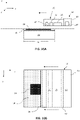
- FIGS 2A-2C are schematic bottom views of example fusing apparatuses 10a-10c of an additive manufacturing machine in accordance with aspects of the present disclosure.
- Figures 3A-3B are graphical representations of heat flux generated by example fusing apparatuses 10a-10c of Figures 2A-2C in accordance with aspects of the present disclosure.
- warming and fusing sources 24, 26 each include lamps.
- Fusing source 26 can include any suitable number and type of lamps to heat and irradiate build material.
- each of the warming and fusing sources 24, 26 includes quartz infrared halogen lamps with each of the quartz infrared halogen lamps having a segmented filament.
- Fusing source 26 can include a series of thermal lamps each being longitudinally arranged in parallel with major axes disposed along the y-axis.
- warming source 24 can include a series of thermal lamps each being longitudinally arranged in parallel with major axes disposed along the y-axis.
- warming source 24a and fusing source 26a each emit a uniform heat flux along respective major axes to provide a substantially uniform heat flux density in the build chamber.
- warming and fusing sources 24a, 26a each includes quartz infrared halogen lamps with each of the quartz infrared halogen lamps having a segmented filament spaced at a distance normal from build material such that the heat flux on build material is uniform.
- the uniform heat flux emitted by warming and fusing sources 24a, 26a creates a substantially uniform heat distribution 28 along the longitudinal major axis.
- a build zone 30 can be positioned along the longitudinal y-axis within the uniform heat flux distribution area.
- fusing source 26 includes a lamp having a first higher coil density at opposing end sections of the filament than a second coil density along a central portion in order to emit increased power at the end sections to offset thermal conduction to walls of build chamber.
- a lamp axis profile for fusing source 26 includes increased power at opposing ends of the lamp filament to counteract conductive and convective losses within the build chamber.
- a peak to center variation is produced using increased power at opposing ends of the lamp filament of fusing lamps.
- lamps of either one or both of warming source 24b and fusing source 26b can each emit non-uniform heat flux along the longitudinal major axes to form a non-uniform heat distribution.
- the non-uniform heat flux of warming and fusing sources 24b, 26b can be modified along the longitudinal major axes to deliver a uniform heat distribution 29 to the build material in build zone 30 during the build process.
- the non-uniform heat flux of warming and fusing sources 24b, 26b in combination with a flux modifier 32 can be employed to deliver a uniform heat distribution.
- flux modifier 32 such one or multiple of a reflector, a field stop, a lens, a reflective filter, and an absorptive filter can be employed.
- Flux modifier 32 can modify a portion of the heat distribution emitted from the series of non-uniform heat sources to correct the heat flux into a substantially uniform heat flux density.
- dashed line 31 indicates the uncorrected heat distribution emitted from the series of non-uniform heat sources and solid line 29 indicates the correct heat flux density.
- a build zone 30 can be positioned along the longitudinal y-axis within the uniform heat flux distribution area.
- the lamps of either one or both of warming source 24c and fusing source 26c can emit non-uniform heat flux along the major axes.
- lamps of warming and fusing sources 24, 26 can be arranged in a longitudinally overlapping pattern along the major axis of warming source 24 to form a first and a second longitudinally uniform heat fluxes, respectively.
- lamps can be colder at end regions than at middle regions.
- Adjacent lamps can be arranged by longitudinally overlapping roll off, or colder, end regions with radiant energy of overlapping cold ends being additive such that the total energy transfer in the overlapped end regions being equivalent to the energy transfer from the warmer non-overlapping middle regions.
- FIG 4 is a flow chart of an example method 40 of operating an additive manufacturing machine in accordance with aspects of the present disclosure.
- thermal energy is generated with a thermic source including a warming source and a fusing source.
- Each of the warming and fusing sources have a major axis longitudinally extending in a y-axial direction above a build zone.
- Build zone can contain a build material and a fusing agent.
- thermic source is moved in an x-axial direction orthogonal to the y-axial direction over the build zone at a constant velocity.
- a first substantially uniform heat flux from the warming source and a second substantially uniform heat flux from the fusing source is delivered to cause portions of the build material that the fusing agent is disposed on to form a layer of a three dimensional object.
- thermic energy is continuously generating from the thermic source during a build process of the three dimensional object.
- FIG. 5 is a flow chart of another example method 50 of operating an additive manufacturing machine in accordance with aspects of the present disclosure.
- thermal energy is generated with a thermic source comprising of two lamp sources disposed in an x-axial direction from one another. Each of the two lamp sources emits thermic energy along a major axis extending in a y-axial direction.
- a first and second uniform heat distribution is produced across the major axis of each of the two lamp sources, respectively.
- the thermic source is translated in the x-axial direction over a build zone.
- the thermic source is translated at a constant velocity to deliver a substantially uniform heat flux from the thermic source to the build material and the fusing agent on the build zone.
- thermic energy is continuously emitted from the thermic source during a build process of build material and the fusing agent.
- Figure 6 illustrates one example of additive manufacturing machine 100 including fusing apparatus 10.
- additive manufacturing machine 100 includes a dispensing assembly 60 and a controller 62.
- Fusing assembly 10 and dispensing assembly 60 are movable along the x-axis over build chamber 12.
- Dispensing assembly 60 includes a printhead 64 (or other suitable liquid dispensing assemblies) mounted to a dispensing carriage 66 to selectively dispense fusing agent 20 and other liquid agents, if used.
- Build chamber 12 can contain build material 18 and fusing agent 20 as layers are formed.
- Build chamber 12 can be any suitable structure to support or contain build material 18 in build zone 30 for fusing, including underlying layers of build material 18 and in-process slice and other object structures.
- build chamber 12 can include a surface of a platform that can be moved vertically along the y-axis to accommodate the layering process.
- build zone 30 can be formed on an underlying build structure within build chamber 12 including unfused and fused build material forming an object slice.
- Controller 62 can operations of additive manufacturing machine 100.
- FIGS 7A-10B are side and top schematic views illustrating an example sequence of a four pass fusing cycle using fusing apparatus 10 of an additive manufacturing machine. Each pass includes multiple operations that can occur simultaneously during the respective pass.
- Fusing apparatus 10 and dispensing assembly 60 move bi-directionally over build zone 30 within build chamber 12 along the same line of motion so that carriages 14, 66 can follow each other across build zone 30.
- a dual carriage fusing system in which carriages 14, 66 move along the same line of motion helps enable faster slew speeds and overlapping functions in each pass.
- the direction of movement of the passes, in accordance with one example, is indicated by arrows in Figures 7A-10B .
- Carriages 14, 66 of fusing apparatus 10 and dispensing assembly 60 can move completely and entirely across build zone 30 and can be positioned on either side of build zone 30.
- a roller 68 of fuser carriage 14 spreads build material 18 to form layers over build zone 30.
- Dispenser carriage 66 carries agent dispenser 64 to dispense fusing agent 20 on to each layer of build material 18.
- Thermic source 16 carried by carriage 14 heats and irradiates layered build material 18 and fusing agent 20.
- Thermic source 16 is spaced a normal vector distance from build material 18 during the build process.
- Second pass is illustrated in Figures 8A and 8B .
- warming lamp 24 is on to heat the new layer of build material 18 in advance of dispenser carriage 66, which follows fuser carriage 14 over build zone 30 to dispense fusing and/or detailing agents on to the heated build material 18 in a pattern based on a next object slice.
- Roller 68 can complete spreading build material 18 that may not be completely spread during first pass, in advance of warming lamp 24 and dispenser carriage 66.
- Third pass is illustrated in Figures 9A and 9B .
- Third pass is a fusing pass.
- dispenser carriage 66 moves back over build zone 30, from left to right, to dispense fusing and/or detailing agents 20 on to build material 18, followed by fuser carriage 14 with fusing lamp 26 on to expose patterned build material to fusing energy.
- the four pass process may be repeated for successive layers of build material as the object is manufactured layer by layer and slice by slice.
- each pass is performed at a slew speed of 22-25 inches per second (ips).
- the slew speed can vary depending on the type of build material employed. Moving fusing system over build zone at a constant uniform velocity during each pass aids in providing uniformity of heat flux density on build material.
Landscapes
- Engineering & Computer Science (AREA)
- Chemical & Material Sciences (AREA)
- Materials Engineering (AREA)
- Manufacturing & Machinery (AREA)
- Mechanical Engineering (AREA)
- Physics & Mathematics (AREA)
- Optics & Photonics (AREA)
- Health & Medical Sciences (AREA)
- General Health & Medical Sciences (AREA)
- Toxicology (AREA)
- Powder Metallurgy (AREA)
Claims (7)
- Procédé de fonctionnement d'une machine de fabrication additive, comprenant :la génération de l'énergie thermique avec une source thermique comportant une source de réchauffement et une source de fusion, chacune des sources de réchauffement et de fusion ayant un axe principal s'étendant longitudinalement dans une direction axiale y au-dessus d'une zone de construction, la zone de construction devant contenir un matériau de construction et un agent de fusion ;le déplacement de la source thermique dans une direction axiale x orthogonale vers la direction axiale y sur la zone de construction à une vitesse constante ;la distribution d'un premier flux thermique sensiblement uniforme à partir de la source de réchauffement et d'un second flux thermique sensiblement uniforme à partir de la source de fusion pour amener des parties du matériau de construction sur lesquelles l'agent de fusion est disposé à former une couche d'un objet tridimensionnel, la distribution du premier et du second flux thermiques sensiblement uniformes comprenant :l'émission d'un flux de chaleur non uniforme le long de l'axe principal de chacune des sources de réchauffement et de fusion, etla modification, à l'aide d'un modificateur de flux, d'une partie du flux de chaleur non uniforme le long de l'axe principal de chacune des sources de réchauffement et de fusion, pour fournir les premier et second flux de chaleur sensiblement uniformes au matériau de construction pendant le processus de construction ; etla génération en continu d'énergie thermique à partir de la source thermique pendant un processus de construction de l'objet tridimensionnel.
- Procédé selon la revendication 1, dans lequel le modificateur de flux comprend un réflecteur et/ou un diaphragme de champ et/ou une lentille et/ou un filtre réfléchissant et/ou un filtre absorbant.
- Procédé de fonctionnement d'une machine de fabrication additive, comprenant :la génération de l'énergie thermique avec une source thermique comportant une source de réchauffement et une source de fusion, chacune des sources de réchauffement et de fusion ayant un axe principal s'étendant longitudinalement dans une direction axiale y au-dessus d'une zone de construction, la zone de construction devant contenir un matériau de construction et un agent de fusion, chacune des sources de réchauffement et de fusion comportant des lampes halogènes infrarouges à quartz, chacune des lampes halogènes infrarouges à quartz ayant un filament segmenté ayant une première densité de bobine au niveau des sections d'extrémité opposées et une seconde densité de bobine au niveau d'une section centrale s'étendant entre les sections d'extrémité opposées, la première densité de bobine étant supérieure à la seconde densité de bobine ;le déplacement de la source thermique dans une direction axiale x orthogonale vers la direction axiale y sur la zone de construction à une vitesse constante ;la distribution d'un premier flux thermique sensiblement uniforme à partir de la source de réchauffement et d'un second flux thermique sensiblement uniforme à partir de la source de fusion pour amener des parties du matériau de construction sur lesquelles l'agent de fusion est disposé à former une couche d'un objet tridimensionnel ; etla génération en continu d'énergie thermique à partir de la source thermique pendant un processus de construction de l'objet tridimensionnel.
- Procédé selon la revendication 1 ou la revendication 3, dans lequel la source de réchauffement doit chauffer le matériau de construction dans des emplacements où l'agent de fusion est absent et la source de fusion doit chauffer les parties du matériau de construction dans des emplacements sur lesquels l'agent de fusion est disposé pour amener à construire le matériau de fusion.
- Appareil de fusion (10) pour une machine de fabrication additive, comprenant :un chariot (14) à déplacer à travers une chambre de construction (12) dans les deux sens le long d'un axe x à une vitesse uniforme dans chaque direction pendant un processus de construction ; etune source thermique (16) montée sur le chariot, la source thermique pouvant se déplacer avec le chariot dans la direction axiale x, la source thermique comprenant une source de réchauffement (24) et une source de fusion (26), la source de fusion comportant une série de sources de chaleur non uniformes s'étendant chacune longitudinalement dans une direction axiale y orthogonale à l'axe x formant une densité de flux thermique sensiblement uniforme dans la direction axiale y ;la source thermique étant une lampe halogène infrarouge à quartz, et la lampe halogène infrarouge à quartz comportant un filament segmenté ayant une première densité de bobine au niveau des sections d'extrémité opposées et une seconde densité de bobine au niveau d'une section centrale s'étendant entre les sections d'extrémité opposées, la première densité de bobine étant supérieure à la seconde densité de bobine.
- Appareil de fusion (10) pour une machine de fabrication additive, comprenant :un chariot (14) à déplacer à travers une chambre de construction (12) dans les deux sens le long d'un axe x à une vitesse uniforme dans chaque direction pendant un processus de construction ;une source thermique (16) montée sur le chariot, la source thermique pouvant se déplacer avec le chariot dans la direction axiale x, la source thermique comprenant une source de réchauffement (24) et une source de fusion (26), la source de fusion comportant une série de sources de chaleur non uniformes s'étendant chacune longitudinalement dans une direction axiale y orthogonale à l'axe x formant une densité de flux thermique sensiblement uniforme dans la direction axiale y ; etun modificateur de flux (32) pour modifier une partie d'un flux thermique émis, le long de la direction axiale y, à partir de la série de sources de chaleur non uniformes en densité de flux thermique sensiblement uniforme.
- Appareil de fusion (10) selon la revendication 6, dans lequel le modificateur de flux comprend :
un réflecteur et/ou un diaphragme de champ et/ou une lentille et/ou un filtre réfléchissant et/ou un filtre absorbant afin de modifier la partie du flux thermique émise par la série de sources de chaleur non uniformes en densité de flux thermique sensiblement uniforme.
Applications Claiming Priority (1)
| Application Number | Priority Date | Filing Date | Title |
|---|---|---|---|
| PCT/US2017/028845 WO2018194656A1 (fr) | 2017-04-21 | 2017-04-21 | Flux de chaleur de machine de fabrication additive |
Publications (3)
| Publication Number | Publication Date |
|---|---|
| EP3582951A1 EP3582951A1 (fr) | 2019-12-25 |
| EP3582951A4 EP3582951A4 (fr) | 2020-11-04 |
| EP3582951B1 true EP3582951B1 (fr) | 2022-06-22 |
Family
ID=63855976
Family Applications (1)
| Application Number | Title | Priority Date | Filing Date |
|---|---|---|---|
| EP17906197.3A Active EP3582951B1 (fr) | 2017-04-21 | 2017-04-21 | Flux de chaleur de machine de fabrication additive |
Country Status (4)
| Country | Link |
|---|---|
| US (1) | US11254055B2 (fr) |
| EP (1) | EP3582951B1 (fr) |
| CN (1) | CN110573325A (fr) |
| WO (1) | WO2018194656A1 (fr) |
Families Citing this family (4)
| Publication number | Priority date | Publication date | Assignee | Title |
|---|---|---|---|---|
| EP3582951B1 (fr) | 2017-04-21 | 2022-06-22 | Hewlett-Packard Development Company, L.P. | Flux de chaleur de machine de fabrication additive |
| US11440252B2 (en) | 2018-07-26 | 2022-09-13 | Essentium, Inc. | High speed extrusion 3D printer nozzle |
| US11065811B2 (en) | 2019-03-20 | 2021-07-20 | Essentium, Inc. | Three-dimensional printer head including an automatic touchdown apparatus |
| US20250153436A1 (en) * | 2022-02-02 | 2025-05-15 | Hewlett-Packard Development Company, L.P. | Additive manufacturing with fusing and warming energy sources |
Citations (5)
| Publication number | Priority date | Publication date | Assignee | Title |
|---|---|---|---|---|
| US5740314A (en) | 1995-08-25 | 1998-04-14 | Edison Welding Institute | IR heating lamp array with reflectors modified by removal of segments thereof |
| WO2007114895A2 (fr) | 2006-04-06 | 2007-10-11 | Z Corporation | production d'éléments tridimensionnels au moyen de radiations électromagnétiques |
| DE102013004940A1 (de) | 2012-10-15 | 2014-04-17 | Voxeljet Ag | Verfahren und Vorrichtung zum Herstellen von dreidimensionalen Modellen mit temperiertem Druckkopf |
| WO2015106832A1 (fr) | 2014-01-16 | 2015-07-23 | Hewlett-Packard Development Company, L.P. | Génération d'un objet tridimensionnel |
| WO2018194656A1 (fr) | 2017-04-21 | 2018-10-25 | Hewlett-Packard Development Company, L.P. | Flux de chaleur de machine de fabrication additive |
Family Cites Families (26)
| Publication number | Priority date | Publication date | Assignee | Title |
|---|---|---|---|---|
| JP3308732B2 (ja) | 1994-11-02 | 2002-07-29 | キヤノン株式会社 | 定着器制御装置 |
| US7027887B2 (en) | 2002-07-03 | 2006-04-11 | Theries, Llc | Apparatus, systems and methods for use in three-dimensional printing |
| GB0317387D0 (en) * | 2003-07-25 | 2003-08-27 | Univ Loughborough | Method and apparatus for combining particulate material |
| US20050242473A1 (en) | 2004-04-28 | 2005-11-03 | 3D Systems, Inc. | Uniform thermal distribution imaging |
| WO2007039450A1 (fr) | 2005-09-20 | 2007-04-12 | Pts Software Bv | Appareil destiné à la fabrication d’un article tridimensionnel et procédé de fabrication de cet article |
| DE102007024469B4 (de) | 2007-05-25 | 2009-04-23 | Eos Gmbh Electro Optical Systems | Verfahren zum schichtweisen Herstellen eines dreidimensionalen Objekts |
| US20120017829A1 (en) | 2010-07-21 | 2012-01-26 | Xenon Corporation | Reduction of stray light during sinterinig |
| GB2493398B (en) * | 2011-08-05 | 2016-07-27 | Univ Loughborough | Methods and apparatus for selectively combining particulate material |
| US8646877B2 (en) | 2011-09-29 | 2014-02-11 | Xerox Corporation | Pre-treatment methods, apparatus, and systems for contact leveling radiation curable gel inks |
| US10518490B2 (en) * | 2013-03-14 | 2019-12-31 | Board Of Regents, The University Of Texas System | Methods and systems for embedding filaments in 3D structures, structural components, and structural electronic, electromagnetic and electromechanical components/devices |
| JP5672289B2 (ja) | 2012-10-18 | 2015-02-18 | カシオ計算機株式会社 | 立体画像形成装置及び立体画像形成方法 |
| CN103030120B (zh) | 2012-12-29 | 2014-07-16 | 河北工业大学 | 硼碳氮纳米管的制备方法 |
| WO2014144630A1 (fr) | 2013-03-15 | 2014-09-18 | Matterfab Corp. | Cartouche pour un appareil de fabrication additive et procédé |
| DE102013109162A1 (de) * | 2013-08-23 | 2015-02-26 | Fit Fruth Innovative Technologien Gmbh | Vorrichtung zum Herstellen dreidimensionaler Objekte |
| CN115723335A (zh) * | 2013-10-17 | 2023-03-03 | Xjet有限公司 | 用于三维(3d)打印的支撑物油墨 |
| US20150165681A1 (en) | 2013-12-18 | 2015-06-18 | Board Of Regents, The University Of Texas System | Real-time process control for additive manufacturing |
| US20170203513A1 (en) * | 2014-01-16 | 2017-07-20 | Hewlett-Packard Development Company, L.P. | Generating a three-dimensional object |
| TW201607740A (zh) | 2014-07-10 | 2016-03-01 | 惠普發展公司有限責任合夥企業 | 產生三維物件之技術 |
| US20160067929A1 (en) | 2014-09-09 | 2016-03-10 | Ricoh Company, Ltd. | Apparatus for fabricating three-dimensional object |
| WO2016048348A1 (fr) | 2014-09-26 | 2016-03-31 | Hewlett-Packard Development Company, L.P. | Dispositif d'éclairage pour procédé de fabrication additive |
| DE102015006533A1 (de) * | 2014-12-22 | 2016-06-23 | Voxeljet Ag | Verfahren und Vorrichtung zum Herstellen von 3D-Formteilen mit Schichtaufbautechnik |
| EP3250363B1 (fr) | 2015-01-30 | 2020-07-15 | Hewlett-Packard Development Company, L.P. | Génération d'objets en 3d |
| US9855704B2 (en) | 2015-02-27 | 2018-01-02 | Technology Research Association For Future Additive Manufacturing | Powder recoater |
| CN107530968A (zh) * | 2015-07-30 | 2018-01-02 | 惠普发展公司有限责任合伙企业 | 用于3d打印的受控加热 |
| CN106270877B (zh) | 2016-09-28 | 2019-11-15 | 深圳市艾贝特电子科技有限公司 | 基于fpc金手指激光锡焊装置及焊接方法 |
| WO2018109735A2 (fr) * | 2016-12-18 | 2018-06-21 | Csir | Préchauffage de matériau dans un appareil de fabrication additive |
-
2017
- 2017-04-21 EP EP17906197.3A patent/EP3582951B1/fr active Active
- 2017-04-21 CN CN201780089694.2A patent/CN110573325A/zh active Pending
- 2017-04-21 US US16/075,920 patent/US11254055B2/en active Active
- 2017-04-21 WO PCT/US2017/028845 patent/WO2018194656A1/fr not_active Ceased
Patent Citations (5)
| Publication number | Priority date | Publication date | Assignee | Title |
|---|---|---|---|---|
| US5740314A (en) | 1995-08-25 | 1998-04-14 | Edison Welding Institute | IR heating lamp array with reflectors modified by removal of segments thereof |
| WO2007114895A2 (fr) | 2006-04-06 | 2007-10-11 | Z Corporation | production d'éléments tridimensionnels au moyen de radiations électromagnétiques |
| DE102013004940A1 (de) | 2012-10-15 | 2014-04-17 | Voxeljet Ag | Verfahren und Vorrichtung zum Herstellen von dreidimensionalen Modellen mit temperiertem Druckkopf |
| WO2015106832A1 (fr) | 2014-01-16 | 2015-07-23 | Hewlett-Packard Development Company, L.P. | Génération d'un objet tridimensionnel |
| WO2018194656A1 (fr) | 2017-04-21 | 2018-10-25 | Hewlett-Packard Development Company, L.P. | Flux de chaleur de machine de fabrication additive |
Also Published As
| Publication number | Publication date |
|---|---|
| US11254055B2 (en) | 2022-02-22 |
| EP3582951A4 (fr) | 2020-11-04 |
| CN110573325A (zh) | 2019-12-13 |
| US20210213682A1 (en) | 2021-07-15 |
| WO2018194656A1 (fr) | 2018-10-25 |
| EP3582951A1 (fr) | 2019-12-25 |
Similar Documents
| Publication | Publication Date | Title |
|---|---|---|
| US11305487B2 (en) | Additive manufacturing roller within radiative heat transfer area | |
| EP3582951B1 (fr) | Flux de chaleur de machine de fabrication additive | |
| US11654626B2 (en) | Additive manufacturing | |
| CN105764673B (zh) | 用于制造三维物体的设备 | |
| JP6460554B2 (ja) | 3d物体の生成 | |
| EP3318389B1 (fr) | Systèmes et procédés de régulation thermique de fabrication d'additifs | |
| KR102129723B1 (ko) | 융해 이전의 온도 제어 기법 | |
| EP3558636B1 (fr) | Procédé de contrôle de trajectoires de panache dans la fabrication additive | |
| TW201838793A (zh) | 具有能量束與燈陣列之積層製造 | |
| EP3558637B1 (fr) | Procédé d'évitement d'interférence de panaches en fabrication additive | |
| CN108248024A (zh) | 用于三维物体的生产性制造的方法和装置 | |
| US11383434B2 (en) | Fusing three-dimensional (3D) object layers | |
| CN109072601B (zh) | 在增材制造中控制加热 | |
| GB2550338A (en) | Reflector and additive manufacturing system | |
| US20210206079A1 (en) | Additive manufacturing machine optical filter | |
| EP3565704B1 (fr) | Fabrication additive | |
| CN110325345B (zh) | 增材制造 | |
| US20200353686A1 (en) | Lighting assembly for additive manufacturing | |
| WO2019125406A1 (fr) | Chauffage variable en fabrication additive | |
| EP3911496B1 (fr) | Commande de rouleau pour imprimante 3d | |
| US11181244B2 (en) | Lighting assembly |
Legal Events
| Date | Code | Title | Description |
|---|---|---|---|
| STAA | Information on the status of an ep patent application or granted ep patent |
Free format text: STATUS: THE INTERNATIONAL PUBLICATION HAS BEEN MADE |
|
| PUAI | Public reference made under article 153(3) epc to a published international application that has entered the european phase |
Free format text: ORIGINAL CODE: 0009012 |
|
| STAA | Information on the status of an ep patent application or granted ep patent |
Free format text: STATUS: REQUEST FOR EXAMINATION WAS MADE |
|
| 17P | Request for examination filed |
Effective date: 20190918 |
|
| AK | Designated contracting states |
Kind code of ref document: A1 Designated state(s): AL AT BE BG CH CY CZ DE DK EE ES FI FR GB GR HR HU IE IS IT LI LT LU LV MC MK MT NL NO PL PT RO RS SE SI SK SM TR |
|
| AX | Request for extension of the european patent |
Extension state: BA ME |
|
| DAV | Request for validation of the european patent (deleted) | ||
| DAX | Request for extension of the european patent (deleted) | ||
| A4 | Supplementary search report drawn up and despatched |
Effective date: 20201005 |
|
| RIC1 | Information provided on ipc code assigned before grant |
Ipc: B33Y 10/00 20150101ALI20200929BHEP Ipc: B33Y 30/00 20150101ALI20200929BHEP Ipc: B22F 3/105 20060101ALI20200929BHEP Ipc: B29C 64/153 20170101ALI20200929BHEP Ipc: B29C 64/295 20170101AFI20200929BHEP Ipc: B29C 64/129 20170101ALI20200929BHEP Ipc: B29C 64/10 20170101ALI20200929BHEP Ipc: B29C 64/165 20170101ALI20200929BHEP |
|
| REG | Reference to a national code |
Ref country code: DE Ref legal event code: R079 Ref document number: 602017058887 Country of ref document: DE Free format text: PREVIOUS MAIN CLASS: B29C0064295000 Ipc: B29C0064165000 |
|
| GRAP | Despatch of communication of intention to grant a patent |
Free format text: ORIGINAL CODE: EPIDOSNIGR1 |
|
| STAA | Information on the status of an ep patent application or granted ep patent |
Free format text: STATUS: GRANT OF PATENT IS INTENDED |
|
| RIC1 | Information provided on ipc code assigned before grant |
Ipc: B33Y 30/00 20150101ALI20220113BHEP Ipc: B33Y 10/00 20150101ALI20220113BHEP Ipc: B22F 12/45 20210101ALI20220113BHEP Ipc: B22F 12/44 20210101ALI20220113BHEP Ipc: B22F 12/13 20210101ALI20220113BHEP Ipc: B29C 64/295 20170101ALI20220113BHEP Ipc: B22F 10/14 20210101ALI20220113BHEP Ipc: B29C 64/153 20170101ALI20220113BHEP Ipc: B29C 64/165 20170101AFI20220113BHEP |
|
| INTG | Intention to grant announced |
Effective date: 20220210 |
|
| GRAS | Grant fee paid |
Free format text: ORIGINAL CODE: EPIDOSNIGR3 |
|
| GRAA | (expected) grant |
Free format text: ORIGINAL CODE: 0009210 |
|
| STAA | Information on the status of an ep patent application or granted ep patent |
Free format text: STATUS: THE PATENT HAS BEEN GRANTED |
|
| AK | Designated contracting states |
Kind code of ref document: B1 Designated state(s): AL AT BE BG CH CY CZ DE DK EE ES FI FR GB GR HR HU IE IS IT LI LT LU LV MC MK MT NL NO PL PT RO RS SE SI SK SM TR |
|
| REG | Reference to a national code |
Ref country code: GB Ref legal event code: FG4D |
|
| REG | Reference to a national code |
Ref country code: CH Ref legal event code: EP |
|
| REG | Reference to a national code |
Ref country code: DE Ref legal event code: R096 Ref document number: 602017058887 Country of ref document: DE |
|
| REG | Reference to a national code |
Ref country code: AT Ref legal event code: REF Ref document number: 1499507 Country of ref document: AT Kind code of ref document: T Effective date: 20220715 |
|
| REG | Reference to a national code |
Ref country code: IE Ref legal event code: FG4D |
|
| REG | Reference to a national code |
Ref country code: LT Ref legal event code: MG9D |
|
| REG | Reference to a national code |
Ref country code: NL Ref legal event code: MP Effective date: 20220622 |
|
| PG25 | Lapsed in a contracting state [announced via postgrant information from national office to epo] |
Ref country code: SE Free format text: LAPSE BECAUSE OF FAILURE TO SUBMIT A TRANSLATION OF THE DESCRIPTION OR TO PAY THE FEE WITHIN THE PRESCRIBED TIME-LIMIT Effective date: 20220622 Ref country code: NO Free format text: LAPSE BECAUSE OF FAILURE TO SUBMIT A TRANSLATION OF THE DESCRIPTION OR TO PAY THE FEE WITHIN THE PRESCRIBED TIME-LIMIT Effective date: 20220922 Ref country code: LT Free format text: LAPSE BECAUSE OF FAILURE TO SUBMIT A TRANSLATION OF THE DESCRIPTION OR TO PAY THE FEE WITHIN THE PRESCRIBED TIME-LIMIT Effective date: 20220622 Ref country code: HR Free format text: LAPSE BECAUSE OF FAILURE TO SUBMIT A TRANSLATION OF THE DESCRIPTION OR TO PAY THE FEE WITHIN THE PRESCRIBED TIME-LIMIT Effective date: 20220622 Ref country code: GR Free format text: LAPSE BECAUSE OF FAILURE TO SUBMIT A TRANSLATION OF THE DESCRIPTION OR TO PAY THE FEE WITHIN THE PRESCRIBED TIME-LIMIT Effective date: 20220923 Ref country code: FI Free format text: LAPSE BECAUSE OF FAILURE TO SUBMIT A TRANSLATION OF THE DESCRIPTION OR TO PAY THE FEE WITHIN THE PRESCRIBED TIME-LIMIT Effective date: 20220622 Ref country code: BG Free format text: LAPSE BECAUSE OF FAILURE TO SUBMIT A TRANSLATION OF THE DESCRIPTION OR TO PAY THE FEE WITHIN THE PRESCRIBED TIME-LIMIT Effective date: 20220922 |
|
| REG | Reference to a national code |
Ref country code: AT Ref legal event code: MK05 Ref document number: 1499507 Country of ref document: AT Kind code of ref document: T Effective date: 20220622 |
|
| PG25 | Lapsed in a contracting state [announced via postgrant information from national office to epo] |
Ref country code: RS Free format text: LAPSE BECAUSE OF FAILURE TO SUBMIT A TRANSLATION OF THE DESCRIPTION OR TO PAY THE FEE WITHIN THE PRESCRIBED TIME-LIMIT Effective date: 20220622 Ref country code: LV Free format text: LAPSE BECAUSE OF FAILURE TO SUBMIT A TRANSLATION OF THE DESCRIPTION OR TO PAY THE FEE WITHIN THE PRESCRIBED TIME-LIMIT Effective date: 20220622 |
|
| PG25 | Lapsed in a contracting state [announced via postgrant information from national office to epo] |
Ref country code: NL Free format text: LAPSE BECAUSE OF FAILURE TO SUBMIT A TRANSLATION OF THE DESCRIPTION OR TO PAY THE FEE WITHIN THE PRESCRIBED TIME-LIMIT Effective date: 20220622 |
|
| PG25 | Lapsed in a contracting state [announced via postgrant information from national office to epo] |
Ref country code: SM Free format text: LAPSE BECAUSE OF FAILURE TO SUBMIT A TRANSLATION OF THE DESCRIPTION OR TO PAY THE FEE WITHIN THE PRESCRIBED TIME-LIMIT Effective date: 20220622 Ref country code: SK Free format text: LAPSE BECAUSE OF FAILURE TO SUBMIT A TRANSLATION OF THE DESCRIPTION OR TO PAY THE FEE WITHIN THE PRESCRIBED TIME-LIMIT Effective date: 20220622 Ref country code: RO Free format text: LAPSE BECAUSE OF FAILURE TO SUBMIT A TRANSLATION OF THE DESCRIPTION OR TO PAY THE FEE WITHIN THE PRESCRIBED TIME-LIMIT Effective date: 20220622 Ref country code: PT Free format text: LAPSE BECAUSE OF FAILURE TO SUBMIT A TRANSLATION OF THE DESCRIPTION OR TO PAY THE FEE WITHIN THE PRESCRIBED TIME-LIMIT Effective date: 20221024 Ref country code: ES Free format text: LAPSE BECAUSE OF FAILURE TO SUBMIT A TRANSLATION OF THE DESCRIPTION OR TO PAY THE FEE WITHIN THE PRESCRIBED TIME-LIMIT Effective date: 20220622 Ref country code: EE Free format text: LAPSE BECAUSE OF FAILURE TO SUBMIT A TRANSLATION OF THE DESCRIPTION OR TO PAY THE FEE WITHIN THE PRESCRIBED TIME-LIMIT Effective date: 20220622 Ref country code: CZ Free format text: LAPSE BECAUSE OF FAILURE TO SUBMIT A TRANSLATION OF THE DESCRIPTION OR TO PAY THE FEE WITHIN THE PRESCRIBED TIME-LIMIT Effective date: 20220622 Ref country code: AT Free format text: LAPSE BECAUSE OF FAILURE TO SUBMIT A TRANSLATION OF THE DESCRIPTION OR TO PAY THE FEE WITHIN THE PRESCRIBED TIME-LIMIT Effective date: 20220622 |
|
| PG25 | Lapsed in a contracting state [announced via postgrant information from national office to epo] |
Ref country code: PL Free format text: LAPSE BECAUSE OF FAILURE TO SUBMIT A TRANSLATION OF THE DESCRIPTION OR TO PAY THE FEE WITHIN THE PRESCRIBED TIME-LIMIT Effective date: 20220622 Ref country code: IS Free format text: LAPSE BECAUSE OF FAILURE TO SUBMIT A TRANSLATION OF THE DESCRIPTION OR TO PAY THE FEE WITHIN THE PRESCRIBED TIME-LIMIT Effective date: 20221022 |
|
| REG | Reference to a national code |
Ref country code: DE Ref legal event code: R026 Ref document number: 602017058887 Country of ref document: DE |
|
| PLBI | Opposition filed |
Free format text: ORIGINAL CODE: 0009260 |
|
| PG25 | Lapsed in a contracting state [announced via postgrant information from national office to epo] |
Ref country code: AL Free format text: LAPSE BECAUSE OF FAILURE TO SUBMIT A TRANSLATION OF THE DESCRIPTION OR TO PAY THE FEE WITHIN THE PRESCRIBED TIME-LIMIT Effective date: 20220622 |
|
| PLAX | Notice of opposition and request to file observation + time limit sent |
Free format text: ORIGINAL CODE: EPIDOSNOBS2 |
|
| 26 | Opposition filed |
Opponent name: VOXELJET AG Effective date: 20230322 |
|
| PG25 | Lapsed in a contracting state [announced via postgrant information from national office to epo] |
Ref country code: DK Free format text: LAPSE BECAUSE OF FAILURE TO SUBMIT A TRANSLATION OF THE DESCRIPTION OR TO PAY THE FEE WITHIN THE PRESCRIBED TIME-LIMIT Effective date: 20220622 |
|
| PLBB | Reply of patent proprietor to notice(s) of opposition received |
Free format text: ORIGINAL CODE: EPIDOSNOBS3 |
|
| PG25 | Lapsed in a contracting state [announced via postgrant information from national office to epo] |
Ref country code: SI Free format text: LAPSE BECAUSE OF FAILURE TO SUBMIT A TRANSLATION OF THE DESCRIPTION OR TO PAY THE FEE WITHIN THE PRESCRIBED TIME-LIMIT Effective date: 20220622 |
|
| REG | Reference to a national code |
Ref country code: CH Ref legal event code: PL |
|
| PG25 | Lapsed in a contracting state [announced via postgrant information from national office to epo] |
Ref country code: LU Free format text: LAPSE BECAUSE OF NON-PAYMENT OF DUE FEES Effective date: 20230421 |
|
| REG | Reference to a national code |
Ref country code: BE Ref legal event code: MM Effective date: 20230430 |
|
| PG25 | Lapsed in a contracting state [announced via postgrant information from national office to epo] |
Ref country code: MC Free format text: LAPSE BECAUSE OF FAILURE TO SUBMIT A TRANSLATION OF THE DESCRIPTION OR TO PAY THE FEE WITHIN THE PRESCRIBED TIME-LIMIT Effective date: 20220622 |
|
| PG25 | Lapsed in a contracting state [announced via postgrant information from national office to epo] |
Ref country code: MC Free format text: LAPSE BECAUSE OF FAILURE TO SUBMIT A TRANSLATION OF THE DESCRIPTION OR TO PAY THE FEE WITHIN THE PRESCRIBED TIME-LIMIT Effective date: 20220622 Ref country code: LI Free format text: LAPSE BECAUSE OF NON-PAYMENT OF DUE FEES Effective date: 20230430 Ref country code: IT Free format text: LAPSE BECAUSE OF FAILURE TO SUBMIT A TRANSLATION OF THE DESCRIPTION OR TO PAY THE FEE WITHIN THE PRESCRIBED TIME-LIMIT Effective date: 20220622 Ref country code: CH Free format text: LAPSE BECAUSE OF NON-PAYMENT OF DUE FEES Effective date: 20230430 |
|
| REG | Reference to a national code |
Ref country code: IE Ref legal event code: MM4A |
|
| PG25 | Lapsed in a contracting state [announced via postgrant information from national office to epo] |
Ref country code: BE Free format text: LAPSE BECAUSE OF NON-PAYMENT OF DUE FEES Effective date: 20230430 |
|
| PG25 | Lapsed in a contracting state [announced via postgrant information from national office to epo] |
Ref country code: IE Free format text: LAPSE BECAUSE OF NON-PAYMENT OF DUE FEES Effective date: 20230421 |
|
| PG25 | Lapsed in a contracting state [announced via postgrant information from national office to epo] |
Ref country code: IE Free format text: LAPSE BECAUSE OF NON-PAYMENT OF DUE FEES Effective date: 20230421 |
|
| PG25 | Lapsed in a contracting state [announced via postgrant information from national office to epo] |
Ref country code: BG Free format text: LAPSE BECAUSE OF FAILURE TO SUBMIT A TRANSLATION OF THE DESCRIPTION OR TO PAY THE FEE WITHIN THE PRESCRIBED TIME-LIMIT Effective date: 20220622 |
|
| PG25 | Lapsed in a contracting state [announced via postgrant information from national office to epo] |
Ref country code: BG Free format text: LAPSE BECAUSE OF FAILURE TO SUBMIT A TRANSLATION OF THE DESCRIPTION OR TO PAY THE FEE WITHIN THE PRESCRIBED TIME-LIMIT Effective date: 20220622 |
|
| REG | Reference to a national code |
Ref country code: DE Ref legal event code: R081 Ref document number: 602017058887 Country of ref document: DE Owner name: PERIDOT PRINT LLC, PALO ALTO, US Free format text: FORMER OWNER: HEWLETT-PACKARD DEVELOPMENT COMPANY, L.P., SPRING, TX, US Ref country code: GB Ref legal event code: 732E Free format text: REGISTERED BETWEEN 20250410 AND 20250416 |
|
| REG | Reference to a national code |
Ref country code: DE Ref legal event code: R082 Ref document number: 602017058887 Country of ref document: DE Representative=s name: NOVAGRAAF BREVETS, FR |
|
| PGFP | Annual fee paid to national office [announced via postgrant information from national office to epo] |
Ref country code: DE Payment date: 20250319 Year of fee payment: 9 |
|
| PG25 | Lapsed in a contracting state [announced via postgrant information from national office to epo] |
Ref country code: CY Free format text: LAPSE BECAUSE OF FAILURE TO SUBMIT A TRANSLATION OF THE DESCRIPTION OR TO PAY THE FEE WITHIN THE PRESCRIBED TIME-LIMIT; INVALID AB INITIO Effective date: 20170421 |
|
| PG25 | Lapsed in a contracting state [announced via postgrant information from national office to epo] |
Ref country code: HU Free format text: LAPSE BECAUSE OF FAILURE TO SUBMIT A TRANSLATION OF THE DESCRIPTION OR TO PAY THE FEE WITHIN THE PRESCRIBED TIME-LIMIT; INVALID AB INITIO Effective date: 20170421 |
|
| PLCK | Communication despatched that opposition was rejected |
Free format text: ORIGINAL CODE: EPIDOSNREJ1 |
|
| APAH | Appeal reference modified |
Free format text: ORIGINAL CODE: EPIDOSCREFNO |
|
| APBP | Date of receipt of notice of appeal recorded |
Free format text: ORIGINAL CODE: EPIDOSNNOA2O |
|
| PG25 | Lapsed in a contracting state [announced via postgrant information from national office to epo] |
Ref country code: TR Free format text: LAPSE BECAUSE OF FAILURE TO SUBMIT A TRANSLATION OF THE DESCRIPTION OR TO PAY THE FEE WITHIN THE PRESCRIBED TIME-LIMIT Effective date: 20220622 |
|
| APBQ | Date of receipt of statement of grounds of appeal recorded |
Free format text: ORIGINAL CODE: EPIDOSNNOA3O |
|
| APAH | Appeal reference modified |
Free format text: ORIGINAL CODE: EPIDOSCREFNO |
|
| PGFP | Annual fee paid to national office [announced via postgrant information from national office to epo] |
Ref country code: GB Payment date: 20260319 Year of fee payment: 10 |
|
| PGFP | Annual fee paid to national office [announced via postgrant information from national office to epo] |
Ref country code: FR Payment date: 20260320 Year of fee payment: 10 |