EP3583245B1 - Herstellung von gasdiffusionselektroden mit ionentransport-harzen zur elektrochemischen reduktion von co2 zu chemischen wertstoffen - Google Patents
Herstellung von gasdiffusionselektroden mit ionentransport-harzen zur elektrochemischen reduktion von co2 zu chemischen wertstoffen Download PDFInfo
- Publication number
- EP3583245B1 EP3583245B1 EP18714125.4A EP18714125A EP3583245B1 EP 3583245 B1 EP3583245 B1 EP 3583245B1 EP 18714125 A EP18714125 A EP 18714125A EP 3583245 B1 EP3583245 B1 EP 3583245B1
- Authority
- EP
- European Patent Office
- Prior art keywords
- binder
- gas diffusion
- exchange material
- layer
- metal
- Prior art date
- Legal status (The legal status is an assumption and is not a legal conclusion. Google has not performed a legal analysis and makes no representation as to the accuracy of the status listed.)
- Active
Links
Images




Classifications
-
- C—CHEMISTRY; METALLURGY
- C25—ELECTROLYTIC OR ELECTROPHORETIC PROCESSES; APPARATUS THEREFOR
- C25B—ELECTROLYTIC OR ELECTROPHORETIC PROCESSES FOR THE PRODUCTION OF COMPOUNDS OR NON-METALS; APPARATUS THEREFOR
- C25B3/00—Electrolytic production of organic compounds
- C25B3/20—Processes
- C25B3/25—Reduction
-
- C—CHEMISTRY; METALLURGY
- C25—ELECTROLYTIC OR ELECTROPHORETIC PROCESSES; APPARATUS THEREFOR
- C25B—ELECTROLYTIC OR ELECTROPHORETIC PROCESSES FOR THE PRODUCTION OF COMPOUNDS OR NON-METALS; APPARATUS THEREFOR
- C25B11/00—Electrodes; Manufacture thereof not otherwise provided for
- C25B11/02—Electrodes; Manufacture thereof not otherwise provided for characterised by shape or form
- C25B11/03—Electrodes; Manufacture thereof not otherwise provided for characterised by shape or form perforated or foraminous
- C25B11/031—Porous electrodes
-
- B—PERFORMING OPERATIONS; TRANSPORTING
- B01—PHYSICAL OR CHEMICAL PROCESSES OR APPARATUS IN GENERAL
- B01D—SEPARATION
- B01D53/00—Separation of gases or vapours; Recovering vapours of volatile solvents from gases; Chemical or biological purification of waste gases, e.g. engine exhaust gases, smoke, fumes, flue gases, aerosols
- B01D53/32—Separation of gases or vapours; Recovering vapours of volatile solvents from gases; Chemical or biological purification of waste gases, e.g. engine exhaust gases, smoke, fumes, flue gases, aerosols by electrical effects other than those provided for in group B01D61/00
- B01D53/326—Separation of gases or vapours; Recovering vapours of volatile solvents from gases; Chemical or biological purification of waste gases, e.g. engine exhaust gases, smoke, fumes, flue gases, aerosols by electrical effects other than those provided for in group B01D61/00 in electrochemical cells
-
- C—CHEMISTRY; METALLURGY
- C01—INORGANIC CHEMISTRY
- C01B—NON-METALLIC ELEMENTS; COMPOUNDS THEREOF; METALLOIDS OR COMPOUNDS THEREOF NOT COVERED BY SUBCLASS C01C
- C01B3/00—Hydrogen; Gaseous mixtures containing hydrogen; Separation of hydrogen from mixtures containing it; Purification of hydrogen; Reversible storage of hydrogen
- C01B3/50—Separation of hydrogen or hydrogen-containing gases from gaseous mixtures, e.g. purification
-
- C—CHEMISTRY; METALLURGY
- C25—ELECTROLYTIC OR ELECTROPHORETIC PROCESSES; APPARATUS THEREFOR
- C25B—ELECTROLYTIC OR ELECTROPHORETIC PROCESSES FOR THE PRODUCTION OF COMPOUNDS OR NON-METALS; APPARATUS THEREFOR
- C25B1/00—Electrolytic production of inorganic compounds or non-metals
- C25B1/01—Products
-
- C—CHEMISTRY; METALLURGY
- C25—ELECTROLYTIC OR ELECTROPHORETIC PROCESSES; APPARATUS THEREFOR
- C25B—ELECTROLYTIC OR ELECTROPHORETIC PROCESSES FOR THE PRODUCTION OF COMPOUNDS OR NON-METALS; APPARATUS THEREFOR
- C25B1/00—Electrolytic production of inorganic compounds or non-metals
- C25B1/01—Products
- C25B1/23—Carbon monoxide or syngas
-
- C—CHEMISTRY; METALLURGY
- C25—ELECTROLYTIC OR ELECTROPHORETIC PROCESSES; APPARATUS THEREFOR
- C25B—ELECTROLYTIC OR ELECTROPHORETIC PROCESSES FOR THE PRODUCTION OF COMPOUNDS OR NON-METALS; APPARATUS THEREFOR
- C25B11/00—Electrodes; Manufacture thereof not otherwise provided for
- C25B11/02—Electrodes; Manufacture thereof not otherwise provided for characterised by shape or form
- C25B11/03—Electrodes; Manufacture thereof not otherwise provided for characterised by shape or form perforated or foraminous
- C25B11/031—Porous electrodes
- C25B11/032—Gas diffusion electrodes
-
- C—CHEMISTRY; METALLURGY
- C25—ELECTROLYTIC OR ELECTROPHORETIC PROCESSES; APPARATUS THEREFOR
- C25B—ELECTROLYTIC OR ELECTROPHORETIC PROCESSES FOR THE PRODUCTION OF COMPOUNDS OR NON-METALS; APPARATUS THEREFOR
- C25B11/00—Electrodes; Manufacture thereof not otherwise provided for
- C25B11/04—Electrodes; Manufacture thereof not otherwise provided for characterised by the material
- C25B11/042—Electrodes formed of a single material
-
- C—CHEMISTRY; METALLURGY
- C25—ELECTROLYTIC OR ELECTROPHORETIC PROCESSES; APPARATUS THEREFOR
- C25B—ELECTROLYTIC OR ELECTROPHORETIC PROCESSES FOR THE PRODUCTION OF COMPOUNDS OR NON-METALS; APPARATUS THEREFOR
- C25B11/00—Electrodes; Manufacture thereof not otherwise provided for
- C25B11/04—Electrodes; Manufacture thereof not otherwise provided for characterised by the material
- C25B11/051—Electrodes formed of electrocatalysts on a substrate or carrier
- C25B11/052—Electrodes comprising one or more electrocatalytic coatings on a substrate
- C25B11/053—Electrodes comprising one or more electrocatalytic coatings on a substrate characterised by multilayer electrocatalytic coatings
-
- C—CHEMISTRY; METALLURGY
- C25—ELECTROLYTIC OR ELECTROPHORETIC PROCESSES; APPARATUS THEREFOR
- C25B—ELECTROLYTIC OR ELECTROPHORETIC PROCESSES FOR THE PRODUCTION OF COMPOUNDS OR NON-METALS; APPARATUS THEREFOR
- C25B11/00—Electrodes; Manufacture thereof not otherwise provided for
- C25B11/04—Electrodes; Manufacture thereof not otherwise provided for characterised by the material
- C25B11/051—Electrodes formed of electrocatalysts on a substrate or carrier
- C25B11/073—Electrodes formed of electrocatalysts on a substrate or carrier characterised by the electrocatalyst material
- C25B11/091—Electrodes formed of electrocatalysts on a substrate or carrier characterised by the electrocatalyst material consisting of at least one catalytic element and at least one catalytic compound; consisting of two or more catalytic elements or catalytic compounds
- C25B11/095—Electrodes formed of electrocatalysts on a substrate or carrier characterised by the electrocatalyst material consisting of at least one catalytic element and at least one catalytic compound; consisting of two or more catalytic elements or catalytic compounds at least one of the compounds being organic
-
- C—CHEMISTRY; METALLURGY
- C25—ELECTROLYTIC OR ELECTROPHORETIC PROCESSES; APPARATUS THEREFOR
- C25B—ELECTROLYTIC OR ELECTROPHORETIC PROCESSES FOR THE PRODUCTION OF COMPOUNDS OR NON-METALS; APPARATUS THEREFOR
- C25B3/00—Electrolytic production of organic compounds
- C25B3/01—Products
-
- C—CHEMISTRY; METALLURGY
- C25—ELECTROLYTIC OR ELECTROPHORETIC PROCESSES; APPARATUS THEREFOR
- C25B—ELECTROLYTIC OR ELECTROPHORETIC PROCESSES FOR THE PRODUCTION OF COMPOUNDS OR NON-METALS; APPARATUS THEREFOR
- C25B3/00—Electrolytic production of organic compounds
- C25B3/01—Products
- C25B3/03—Acyclic or carbocyclic hydrocarbons
-
- C—CHEMISTRY; METALLURGY
- C25—ELECTROLYTIC OR ELECTROPHORETIC PROCESSES; APPARATUS THEREFOR
- C25B—ELECTROLYTIC OR ELECTROPHORETIC PROCESSES FOR THE PRODUCTION OF COMPOUNDS OR NON-METALS; APPARATUS THEREFOR
- C25B3/00—Electrolytic production of organic compounds
- C25B3/01—Products
- C25B3/07—Oxygen containing compounds
-
- C—CHEMISTRY; METALLURGY
- C25—ELECTROLYTIC OR ELECTROPHORETIC PROCESSES; APPARATUS THEREFOR
- C25B—ELECTROLYTIC OR ELECTROPHORETIC PROCESSES FOR THE PRODUCTION OF COMPOUNDS OR NON-METALS; APPARATUS THEREFOR
- C25B9/00—Cells or assemblies of cells; Constructional parts of cells; Assemblies of constructional parts, e.g. electrode-diaphragm assemblies; Process-related cell features
-
- C—CHEMISTRY; METALLURGY
- C25—ELECTROLYTIC OR ELECTROPHORETIC PROCESSES; APPARATUS THEREFOR
- C25B—ELECTROLYTIC OR ELECTROPHORETIC PROCESSES FOR THE PRODUCTION OF COMPOUNDS OR NON-METALS; APPARATUS THEREFOR
- C25B9/00—Cells or assemblies of cells; Constructional parts of cells; Assemblies of constructional parts, e.g. electrode-diaphragm assemblies; Process-related cell features
- C25B9/17—Cells comprising dimensionally-stable non-movable electrodes; Assemblies of constructional parts thereof
- C25B9/19—Cells comprising dimensionally-stable non-movable electrodes; Assemblies of constructional parts thereof with diaphragms
-
- C—CHEMISTRY; METALLURGY
- C25—ELECTROLYTIC OR ELECTROPHORETIC PROCESSES; APPARATUS THEREFOR
- C25B—ELECTROLYTIC OR ELECTROPHORETIC PROCESSES FOR THE PRODUCTION OF COMPOUNDS OR NON-METALS; APPARATUS THEREFOR
- C25B9/00—Cells or assemblies of cells; Constructional parts of cells; Assemblies of constructional parts, e.g. electrode-diaphragm assemblies; Process-related cell features
- C25B9/17—Cells comprising dimensionally-stable non-movable electrodes; Assemblies of constructional parts thereof
- C25B9/19—Cells comprising dimensionally-stable non-movable electrodes; Assemblies of constructional parts thereof with diaphragms
- C25B9/23—Cells comprising dimensionally-stable non-movable electrodes; Assemblies of constructional parts thereof with diaphragms comprising ion-exchange membranes in or on which electrode material is embedded
Definitions
- the present invention relates to an electrolysis cell, comprising a gas diffusion electrode, comprising a metal M, which is selected from Ag, Au, Cu, Pd and mixtures and / or alloys and / or salts thereof, and at least one binder, as cathode, wherein the gas diffusion electrode comprises hydrophilic and hydrophobic pores and / or channels, the pores and / or channels of the gas diffusion electrode at least partially containing an ion exchange material, a method for their production, their use in the reduction of CO 2 and / or CO, and an electrolysis system, which includes this electrolytic cell.
- a gas diffusion electrode comprising a metal M, which is selected from Ag, Au, Cu, Pd and mixtures and / or alloys and / or salts thereof, and at least one binder, as cathode
- the gas diffusion electrode comprises hydrophilic and hydrophobic pores and / or channels, the pores and / or channels of the gas diffusion electrode at least partially containing an ion exchange material, a method for their production,
- Carbon dioxide is one of the so-called greenhouse gases, the negative effects of which on the atmosphere and the climate are being discussed. It is a technical challenge to produce valuable products from CO 2. Since carbon dioxide is thermodynamically very low, it can only be reduced to recyclable products with difficulty, which has so far left the actual recycling of carbon dioxide in theory or in the academic world.
- a natural breakdown of carbon dioxide occurs, for example, through photosynthesis.
- carbon dioxide is converted into carbohydrates in a process that is broken down into many sub-steps in terms of time and space. This process cannot simply be adapted on a large scale.
- a copy of the natural photosynthesis process with large-scale photocatalysis has so far not been sufficiently efficient.
- Electrolysis cells suitable for the electrochemical reduction of carbon dioxide usually consist of at least one cathode and one anode compartment, whereby a gas compartment, etc. can also be present, for example.
- the cathode is ideally designed as a porous gas diffusion electrode, which is usually made of a mixture of an inorganic metal catalyst (e.g. Ag, Au, Cu, Pb, etc.) and an organic binder (e.g.
- PTFE polytetrafluoroethylene
- PVDF polyvinylenedifluoride
- PFA perfluoroalkoxy polymers
- FEP fluorinated ethylene-propylene copolymers
- PFSA perfluorosulfonic acid polymers
- hydrophilic materials such as polysulfones, for example polyphenylsulfones, polyimides, polybenzoxazoles or polyether ketones or generally polymers that are electrochemically stable in the electrolyte, such as polymerized "ionic liquids", or organic conductors such as PEDOT: PSS or PANI (champhersulfonic acid-sorted polyaniline) can also be used.
- the prepared electrodes are characterized by high pore connectivity and a wide pore radius distribution.
- silver / silver oxide / PTFE-based gas diffusion electrodes have recently been used on an industrial scale for the production of caustic soda in the existing chlor-alkali electrolysis process (oxygen-consuming electrodes).
- the efficiency of the chlor-alkali electrolysis process can be increased by 30-40% compared to conventional electrodes.
- the method of embedding the catalyst with PTFE is known from a large number of publications and patents.
- the "dry process" methodology is based on a roller calendering process of PTFE / catalyst powders.
- the corresponding technology can be traced back to a patent from 1988, EP0297377A2 , wherein Mn 2 O 3 -based electrodes were manufactured for batteries.
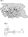
- the DE10148599 A1 and EP0115845B1 describe a similar process in which the powder mixture is first extruded into a skin or film, which is pressed onto the net in a further step, as in, for example Fig. 8 is shown schematically, the catalyst material 6 being placed on the mesh 7 in a two-stage calendering process and being calendered to form the gas diffusion electrode GDE.
- the EP2410079A2 describes the one-step process for the production of a silver-based oxygen-consuming electrode with the addition of metal oxide additives such as TiO 2 , Fe 3 O 4 , Fe 2 O 3 , NiO 2 , Y 2 O 3 , Mn 2 O 3 , Mn 5 O 8 , WO 3 , CeO 2 , Spinels such as CoAl 2 O 4 , Co (AlCr) 2 O 4 , inverse spinels such as (Co, Ni Zn) 2 (Ti, Al) O 4 , and perovskites such as LaNiO 3 , ZnFe 2 O 4 .
- metal oxide additives such as TiO 2 , Fe 3 O 4 , Fe 2 O 3 , NiO 2 , Y 2 O 3 , Mn 2 O 3 , Mn 5 O 8 , WO 3 , CeO 2 , Spinels such as CoAl 2 O 4 , Co (AlCr) 2 O 4 , inverse spinels such as (Co,
- Catalysts which can be used alternatively for the oxygen-consuming electrodes, such as noble metals, e.g. Pt, Rh, Ir, Re, Pd, noble metal alloys, e.g. Pt-Ru, compounds containing noble metals, e.g. sulphides and oxides containing noble metals, and Chevrel phases, e.g. Mo 4 Ru 2 Se 8 or Mo 4 Ru 2 S 8 , which can also contain Pt, Rh, Re, Pd, etc.
- noble metals e.g. Pt, Rh, Ir, Re, Pd
- noble metal alloys e.g. Pt-Ru
- compounds containing noble metals e.g. sulphides and oxides containing noble metals
- Chevrel phases e.g. Mo 4 Ru 2 Se 8 or Mo 4 Ru 2 S 8 , which can also contain Pt, Rh, Re, Pd, etc.
- Known Cu-based gas diffusion electrodes for generating hydrocarbons on the basis of CO 2 are, for example, in the work by R. Cook [J. Electrochem. Soc., Vol. 137, No. 2, 1990 ], where a wet chemical process based on a PTFE 30B (suspension) / Cu (OAc) 2 / Vulkan XC 72 mixture is mentioned.
- the method describes how a hydrophobic conductive gas transport layer is applied using three coating cycles and a catalyst-containing layer is applied using three additional coatings. After each layer application, there is a drying phase (325 ° C) followed by a static pressing process (1000-5000 psi).
- the calendering methods described lead to highly porous single-layer electrodes, which are characterized by low flow resistances or low bubble formation points of approx. 5-20 mbar. Due to the high porosity (50-70%) or the large pore opening radii, which are caused by such a manufacturing method, the electrodes prepared accordingly have very narrow operating times within the CO 2 electrolysis in aqueous electrolytes.
- Electrodes with small bubble formation points react relatively strongly to pressure fluctuations, so that a regulation of the differential pressure (back pressure of the CO 2 behind the electrode) by a differential pressure regulator in a technical application is complicated, as for example in DE102013011298A1 to see, whereby a more complicated control loop with the control parameters: gas composition, pressure and volume flow may be required.
- Polyvinylbenzyl structures are mainly used as the polymer backbone. Copolymers of vinylbenzyl chloride and styrene are also described, poly (4-VBC-co-St). In addition, poly (2,6-dimethyl-1,4-phenylene oxide) is also mentioned.
- the anode and cathode are in direct contact with the membrane. The electrodes are made on the basis of catalyst-coated carbon paper (GDL) (Sigracet 35 BC). It is not an all-catalyst gas diffusion electrode. Reproduction experiments led to stability problems of the ionomer on the anode side.
- the electrodes used in the processes described are based exclusively on catalyst-coated carbon fiber GDL structures that originate from the development field of fuel cells and are usually not suitable for industrially operated electrolysis processes due to their low mechanical stability. Another disadvantage is common the soot or. Coal component, which mostly contains impurities in transition metals such as Ni, Fe, and thus the undesired formation of hydrogen is increased. The adhesion of the catalyst particles to the GDL structure is also usually insufficient, so that a significant catalyst loss occurs when the system is operated for several 100-1000 hours. A similar problem can also be observed with the renewal of membranes, since a large part of the catalyst can be lost when the GDL and membrane are separated. Gas diffusion electrodes, which are constructed according to the all-catalyst concept, have essential advantages over these methods. The applicability of the ionic connection of such electrodes to a membrane is not yet known.
- Anion-exchange membranes are known from other fields of application, such as electrodialysis, for example, but they are not catalyst-modified.
- the use of ion exchange resins in electrolysis cells is known from the field of exchanger regeneration by means of electrodeionization (EDI).
- EDI electrodeionization
- these processes differ fundamentally from the electrochemical reduction of CO 2 .
- the US 2017/012334 A1 discloses an air electrode for a metal-air battery, the air electrode comprising a separator made of a hydroxide-ion conductive inorganic solid electrolyte which is a dense ceramic material.
- gas diffusion electrodes within the electroreduction of CO 2 in aqueous electrolyte solutions is usually possible in a relatively narrow process window over a longer period of> 1000 hours.
- the anode compartment and cathode compartment are typically kept separate from one another in a CO 2 electrolyser with a cation-anion-selective membrane or a diaphragm. This prevents the gaseous valuable substances formed on the cathode and anode from mixing.
- the membranes used are practically impermeable to gases, they must be permeable to ionic charge carriers. Since the membranes commonly used are chemically solid acids, the charge transport can usually only be carried out by positively charged species such as protons or electrolyte cations (e.g.
- the missing cations in the anolyte are replaced by protons generated at the anode. This usually leads either to the evolution of acid in the anolyte, which leads to a drop in the pH, or in the case of, for example, hydroxide or carbonate electrolytes, to the neutralization of the anions. In the former case, the anolyte could be converted into pure water.
- Another problem is the migration of salts into the porous electrode itself. The electrode is not Even ion-conductive, the electrochemically active centers can only be linked to water and ion transport by partially penetrating the electrode with the liquid electrolyte.
- a known cause for the penetration of electrolyte into the pores of the electrode is the hydrostatic pressure of the water column in the electrolyte gap, which limits the technical height of the electrolytic cells.
- an increasing salt crystallization of hydrogen carbonates can be observed in the area of the side facing away from the electrolyte, which in a borderline case can lead to pore clogging, so that an undesired undersupply of the catalyst with CO 2 occurs.
- a strong penetration of the aqueous medium through the pores can be observed, which leads to a Flooding of the pore system and also contributes to a CO 2 undersupply of the catalyst.
- a stable operating state can be achieved by avoiding the borderline cases mentioned.
- One aim of the present invention is therefore to produce gas diffusion electrodes with increased bubble points and wetting pressures in order to widen the operating window of the gas diffusion electrodes and to prevent salinization or the passage of electrolyte.
- the inventors found that in cell structures with an electrolyte gap between the cathode and the membrane / diaphragm, salt precipitations occur in the gas diffusion electrode during CO 2 operation, especially at higher operating temperatures, which lead to the failure of the GDE.
- the inventors have found that in the case of cell structures without an electrolyte gap or when using an M / DEA (membrane / diaphragm electrode assembly) with a gas diffusion electrode as the cathode, it also leads to strong salt formation / excretion in electrolysis in the area of the interface between the gas diffusion electrode (Cathode) and the separator membrane / diaphragm can come, so that a stable electrolysis operation is not guaranteed. Salt formation / precipitation is also independent of whether the anode is located directly on the membrane or whether a separate electrolyte gap has been provided in the cell.
- M / DEA membrane / diaphragm electrode assembly
- anion exchange materials are used as a binder material or additive in the context of the present invention, for example to quickly dissipate or partially buffer the OH - ions so that the reaction with CO 2 and the associated formation of hydrogen carbonates can be reduced or the anion exchange resins HCO 3 - conduct themselves. Since anion exchangers contain cationic functionalities, counterions are already intrinsically present to compensate for the charge to the hydrogen carbonate ions formed, and penetration of cations into the electrode is no longer necessary. Rather, anions can be transported or displaced from the electrode.
- the anion exchange resins thus also provide a path on which, for example, hydroxide or hydrogen carbonate anions can be transported away from the cathode in the direction of the electric field, so that no further cations from the electrolyte have to be used for charge compensation, which in turn lead to crystallization of salts and thus can cause a blockade of the GDE.
- an integrated anion exchanger represents a blockade for cations, which can also counteract salt excretion. It is irrelevant here whether the electrode is completely permeated with the anion exchanger.
- the anion transport functionality in the direction of the electrolyte or in the active area of the GDE is important.
- an electrolysis cell comprising a gas diffusion electrode, comprising a metal M selected from Ag, Au, Cu, Pd, and mixtures and / or alloys and / or salts thereof, and at least one binder, as cathode, wherein the gas diffusion electrode comprises hydrophilic and hydrophobic pores and / or channels, the pores and / or channels of the gas diffusion electrode at least partially containing an ion exchange material, the ion exchange material being an anion exchange material, the anion exchange material not containing imidazolium, pyridinium and ⁇ -hydrogen containing groups.
- an ion transport material is at least partially applied to the surface of the gas diffusion electrode.
- the present invention also relates to an electrolysis system comprising the electrolysis cell according to the invention.
- a method for the electrolysis of CO 2 and / or CO is also disclosed, the electrolysis cell according to the invention being used, as well as the use of the electrolysis cell according to the invention in the electrolysis of CO 2 and / or CO.
- hydrophobic is understood to be water-repellent. According to the invention, hydrophobic pores and / or channels are therefore those which repel water. In particular, according to the invention, hydrophobic properties are associated with substances or molecules with non-polar groups.
- hydrophilic is understood to mean the ability to interact with water and other polar substances.
- the present invention relates to an electrolysis cell comprising a gas diffusion electrode comprising a metal M selected from Ag, Au, Cu, Pd and mixtures and / or alloys and / or salts thereof, and at least one binder, as cathode , the gas diffusion electrode comprising hydrophilic and hydrophobic pores and / or channels, the pores and / or channels of the gas diffusion electrode at least partially containing an ion exchange material, the ion exchange material being an anion exchange material, the anion exchange material not containing any imidazolium, pyridinium or ⁇ - Has hydrogen-containing groups.
- a gas diffusion electrode comprising a metal M selected from Ag, Au, Cu, Pd and mixtures and / or alloys and / or salts thereof, and at least one binder, as cathode
- the gas diffusion electrode comprising hydrophilic and hydrophobic pores and / or channels, the pores and / or channels of the gas diffusion electrode at least partially containing an ion exchange material, the ion exchange
- a gas diffusion electrode comprising a metal M selected from Ag, Au, Cu, Pd and mixtures and / or alloys and / or salts thereof, and at least one binder, the gas diffusion electrode having hydrophilic and hydrophobic pores and / or channels, the pores and / or channels of the gas diffusion electrode at least partially containing an ion transport material and / or at least partially applying an ion transport material to the surface of the gas diffusion electrode.
- the ion transport material can be contained at least partially in the pores and / or channels of the gas diffusion electrode.
- the ion exchange material can be at least partially contained in the pores and / or channels of the gas diffusion electrode and on the surface be applied at least partially to the gas diffusion electrode.
- the metal M can serve both as a catalyst and as an electron conductor in the gas diffusion electrode.
- the metal M is selected from Cu, Ag, Au, Pd, as well as mixtures and / or alloys and / or salts thereof.
- the metal M is preferably selected from Cu, Ag and mixtures and / or alloys and / or salts thereof, in particular Ag and / or alloys and / or salts thereof.
- the salts of the metal M represent, for example, charged compounds of the metal M in which the metal M is present as a cation, preferably as M + and / or M 2+ (in particular Cu 2+ and / or Pd 2+ ), in particular M + , and which contribute to the catalytic reduction.
- the counter ions in these salts are not particularly limited.
- the proportion of metal M in the gas diffusion electrode is not particularly limited and can be between 30 and 99.8% by weight, based on the weight of the gas diffusion electrode, preferably 40% by weight or more and 96% by weight or less, more preferably 50 % By weight or more and 92% by weight or less, more preferably 65% by weight or more and 85% by weight or less.
- the metal M in the gas diffusion electrode can be present both as elemental metal M and in cationic form, preferably as M + and / or M 2+ (in particular Cu and / or Pd), particularly preferably M + .
- the at least one binder contained in the gas diffusion electrode is not particularly limited, and two or more different binders can also be used in different layers of the electrode.
- the binder or the binder for the gas diffusion electrode, if present, is not particularly limited, and includes, for example, a hydrophilic and / or hydrophobic polymer, for example a hydrophobic polymer.
- the at least one binder can be an organic binder, for example selected from PTFE (polytetrafluoroethylene), PVDF (polyvinylenedifluoride), PFA (perfluoroalkoxy polymers), FEP (fluorinated ethylene-propylene copolymers), PFSA (perfluorosulfonic acid polymers), and mixtures thereof , especially PTFE.
- PTFE polytetrafluoroethylene
- PVDF polyvinylenedifluoride
- PFA perfluoroalkoxy polymers
- FEP fluorinated ethylene-propylene copolymers
- PFSA perfluorosulfonic acid polymers
- hydrophilic materials such as polysulfones, ie polyphenyl sulfones, polyimides, polybenzoxazoles or polyether ketones or generally polymers that are electrochemically stable in the electrolyte, such as polymerized "ionic liquids", or organic conductors such as PEDOT: PSS or PANI (champhersulfonic acid-sorted polyaniline) can also be used In this way, a suitable setting of the hydrophobic pores or channels can be achieved.
- PTFE particles with a particle diameter between 0.01 and 95 ⁇ m, preferably between 0.05 and 70 ⁇ m, more preferably between 0.1, can be used to produce the gas diffusion electrode and 40 ⁇ m, for example 0.3 to 20 ⁇ m, for example 0.5 to 20 ⁇ m, for example about 0.5 ⁇ m.
- Suitable PTFE powders include, for example, Dyneon® TF 9205 and Dyneon TF 1750.
- Suitable binder particles for example PTFE particles, can for example be approximately spherical, for example spherical, and can for example by emulsion poly merization can be established. According to certain embodiments, the binder particles are free of surfactants.
- the particle size can for example be determined according to ISO 13321 or D4894-98a and can for example correspond to the manufacturer's specifications (eg TF 9205: mean particle size 8 ⁇ m according to ISO 13321; TF 1750: mean particle size 25 ⁇ m according to ASTM D4894-98a).
- the binder can, for example, in a proportion of 0.1 to 50% by weight, for example when using a hydrophilic ion transport material, for example 0.1 to 30% by weight, preferably from 0.1 to 25% by weight, for example 0.1 to 20% by weight more preferably of 3 to 20% by weight, more preferably 3 to 10% by weight, even more preferably 5 to 10% by weight, based on the gas diffusion electrode.
- the binder has a strongly pronounced shear-thinning behavior, so that fiber formation takes place during the mixing process.
- fibers formed during manufacture should wrap around the particles without completely enclosing the surface.
- the optimal mixing time can be determined, for example, by direct visualization of the fiber formation in the scanning electron microscope.
- the at least one binder is stable at a pH of 7 and more, preferably in a strongly basic environment, for example at a pH of 9 and more, for example 10 and more.
- the metal M, the at least one binder and the anion exchange material, such as an anion exchange resin can be distributed essentially homogeneously.
- the ion exchange material is an anion transport material, for example an anion exchange resin, the anion exchange material not having any groups containing imidazolium, pyridinium and ⁇ -hydrogen.
- the ion exchange material also has a cation blocker function, that is to say it can prevent or at least reduce the penetration of cations into the gas diffusion electrode.
- an anion exchange material with firmly bound cations can represent a blockade for mobile cations through Coulomb repulsion, which can additionally counteract salt excretion, in particular within the gas diffusion electrode. It is irrelevant whether the gas diffusion electrode is completely connected to the anion exchanger is interspersed.
- the anion transport functionality in the direction of the electrolyte or in the active area of the GDE is important.
- the anion exchange material is thus at least partially on a side of the gas diffusion electrode facing an electrolyte, in particular at least partially in the pores and / or channels of the gas diffusion electrode which face an electrolyte, for example a side which is arranged opposite a gas side of the gas diffusion electrode , on which a gas such as CO 2 and / or CO is fed in or bypassed.
- a cation transport e.g. a cation exchange functionality
- a cation transport can be disadvantageous here, as it can promote hydrogen formation on the one hand, and can provide paths for cations in the electrolyte on the other hand, which can lead to salt excretion.
- anion transport by means of an anion exchange material in particular at least partially in pores and / or channels of the gas diffusion electrode, in particular on a side of the gas diffusion electrode facing an electrolyte, are illustrated below.
- an anion transport additive is not absolutely necessary for the operation of a GDE, for example an oxygen-consuming cathode, up to high current densities, for example above 500 mA / cm 2.
- Fig. 24 the basic state of a GDE, for example an oxygen-consuming cathode or a GDE for converting CO 2 and / or CO, is shown without applied voltage.
- the electrolyte 45 can here penetrate the porous catalyst, here an exemplary silver catalyst Ag, with PTFE being used here as a binding material, for example.
- All cations (eg K + ) are balanced by anions (eg HCO 3 - or SO 4 2- ), with mobile cations 51 and mobile anions 52 being shown here by way of example.
- hydroxide ions produced by way of example should now diffuse out of the gas diffusion electrode.
- the diffusion of cations should be suppressed, as otherwise salt crystallization can occur.
- the same electrode can also be used to reduce CO 2 to CO, for example.
- Analogous to the reduction of oxygen two hydroxide ions are formed during the reduction of CO 2. 2e - + CO 2 + H 2 O ⁇ 2 OH- + CO
- the CO formed diffuses out of the electrode and can be discharged with the electrolyte and / or the gas flow.
- the resulting hydroxide ions can also be transported out of the electrode by the Grotthus mechanism. This reaction is sufficient up to a certain current density (eg ⁇ 150 mA / cm 2 ) and low temperature (eg ⁇ 30 ° C) to ensure stable operation.
- Fig. 26 shows an example of the electrochemical reduction of CO 2 to CO with applied voltage with the hydroxide transport through the Grotthus mechanism.
- the equilibrium is unfavorably on the side of the hydrogen carbonate, which can no longer be generated via tunnel processes, but has to be carried out of the electrode via real transport processes, as in Fig. 27 where the summary of the chemical equilibria in the exemplary gas diffusion electrode is shown.
- the migration of cations can lead to salt excretion in the GDE or at least to the formation of permeate on the side of the GDE facing away from the electrolyte.
- the anion exchange material can be introduced into the GDE with any anion. Either it can then be exchanged for OH - or HCO 3 - before installation, for example, or an exchange can take place spontaneously during operation due to the differences in concentration to the electrolyte.
- Fig. 28 an exemplary GDE is shown, the anion exchange material 54 and catalyst, e.g. catalyst particles, eg Ag, provided with an existing binder (here, for example, PTFE) is homogeneously distributed.
- the anion exchange material contains a large number of localized positive charges 55, which can be compensated for by counter ions, for example OH - or HCO 3 -. This creates an anion path along which the anions can move. If an additional ion arises at one point in the GDE due to the electroreduction, which is not compensated at least in statu nascendi , this pushes an anion out at the phase boundary of the GDE through a hopping mechanism.
- the anion exchange material comprises polar groups such as ROR, RCOO - , R-NR 3 + , R-NH 2 , RPO 3 2- , ROH, where R is any radical, for example an organic radical.
- R is any radical, for example an organic radical.
- ion exchange resins with polar Functionalities ROR, RCOO - , R-NR 3 + , R-NH 2 , RPO 3 2- , ROH
- ROR, RCOO - , R-NR 3 + , R-NH 2 , RPO 3 2- , ROH increase the proportions of the hydrophilic areas of the electrode, whereby the electrolyte transport through the electrode can be increased.
- the dilution effect achieved can also counteract supersaturation or salt crystallization, but it should be avoided that they completely flood.
- a multilayer for example a 2-layer structure
- at least one layer does not essentially comprise the ion exchange material, for example one which faces a gas during operation, for example is therefore located on a carrier, in which case no chemical reaction should then preferably take place in this layer, which can be ensured, for example, by setting the gas pressure and / or supplying electrolyte during operation.
- the anion exchange material is stable at a pH greater than 7. According to certain embodiments, the anion exchange material is stable in a strongly basic environment, for example at a pH of 9 and more, for example 10 and more.
- the anion exchanger material is in an amount of 0.1 to 50% by weight, preferably 0.1 to 40% by weight, preferably 3 to 35% by weight, more preferably 5 to 30% by weight, even more preferably 10 Up to 25% by weight, based on the gas diffusion electrode and / or based on the layer, for example a catalyst layer in which it is contained.
- a hydrophilic or predominantly hydrophilic (eg more hydrophilic than hydrophobic areas) anion exchange material, for example anion exchange resin is preferably in an amount of 0.1 to 20% by weight, preferably 1 to 18% by weight, based on the gas diffusion electrode and / or based on the layer, for example a catalyst layer, in which it is contained.
- anion exchange materials also include hydrophobic variants of "anion exchange resins" which, as such, can usually no longer be used in aqueous media. For such, a higher amount is correspondingly possible in the gas diffusion electrode, as indicated above. If the anion exchange material is sufficiently hydrophobic, it can also act as a binder at the same time, which is preferred. The proportion of binder can then also be reduced accordingly.
- an amount of a hydrophilic or predominantly hydrophilic ion exchange material in a gas diffusion electrode is less than an amount of hydrophobic binder, and / or there is at least one layer which contains a greater amount of hydrophobic binder than of hydrophilic or predominantly hydrophilic ion exchange material.
- An undesirable penetration with electrolyte can be obtained, for example, if an amount of hydrophilic or predominantly hydrophilic anion exchange resin used exceeds the amount of hydrophobic binder used beyond the GDE.
- a ratio of more than 20% by weight of hydrophilic or predominantly hydrophilic resin to 7% by weight of PTFE has been identified as problematic.
- Such high contents of exchange resin can be achieved, for example, within the catalyst layer in the case of a two-layer GDE with an essentially hydrophobic base layer made of, for example,> 10% by weight PTFE, without a complete flow being achieved.
- the anion exchange material is added in the form of powder during production, the powder for example having a particle size of 0.1 to 100 ⁇ m, for example 1 to 50 ⁇ m, for example 1 to 20 ⁇ m or 1 to 10 ⁇ m , wherein the powder can also be macroporous, ie aggregated from the above-mentioned particles.
- the particle size can be determined, for example, microscopically by means of image analysis, laser diffraction and / or dynamic light scattering.
- a microemulsion can also be used for impregnation with ion exchange material, in which the ion exchange material can have particle sizes of 0.01 to 10 ⁇ m, e.g. 0.05 to 5 ⁇ m, e.g. 0.1 to 1 ⁇ m.
- the particle size can be determined, for example, microscopically by means of image analysis, laser diffraction and / or dynamic light scattering.
- the anion exchange material is preferably an ion transport polymer, for example also an ion exchange polymer, the polymer structure of the anion exchange material optionally also being may be partially or fully fluorinated.
- the polymer backbone of the anion exchange material is not particularly limited and can, for example, be based on a polymer or copolymer based on, for example, styrene.
- the polymer backbone can be built up, for example, from divinylbenzene-styrene copolymers which have functionalized side chains or are directly functionalized.
- the polymer backbones of the ion transport material are hydrophobic polymer structures based on PTFE (polytetrafluoroethylene), PVDF (polyvinylenedifluoride), PFA (perfluoroalkoxy polymers), FEP (fluorinated ethylene-propylene copolymers), PFSA (perfluorosulfonic acid Polymers), and mixtures thereof, in particular PTFE, possible.
- PTFE polytetrafluoroethylene
- PVDF polyvinylenedifluoride
- PFA perfluoroalkoxy polymers
- FEP fluorinated ethylene-propylene copolymers
- PFSA perfluorosulfonic acid Polymers
- the polymer backbone of the anion exchange material can serve to adjust the hydrophilic / hydrophobic properties of the gas diffusion electrode.
- hydrophilic materials such as polysulfones, e.g. polyphenyl sulfones, polyimides, polybenzoxazoles or polyether ketones or, in general, polymers that are electrochemically stable in the electrolyte, such as, for example, polymerized "ionic liquids".
- Suitable functional groups for ion transport which are also described below by way of example, can be inserted for all of the polymer backbones mentioned, for example by replacing functional groups present there with suitable leaving groups.
- the anion exchange material for example ion exchange polymer
- polar ion exchange resins in the catalyst layer leads to a noticeable increase in the hydrophilic properties of the gas diffusion electrode, so that the overall hydrophilicity can be adjusted.
- an electrolysis cell in an electrolysis cell according to the invention this is preferably in direct contact with an anion exchange membrane and / or an anion exchange diaphragm on the side facing the anode.
- All-catalyst electrodes with only one layer with ionic conductivity are preferably used in direct contact with an anion exchange membrane and / or an anion exchange diaphragm.
- no contact with a membrane and / or a diaphragm is provided here, that is to say a gap.
- the anion exchange material for example an ion exchange polymer or anion exchange resin, can comprise various functional groups for ion exchange, which can be the same or different, for example tertiary amine groups, alkylammonium groups and / or phosphonium groups. According to certain embodiments, the anion exchange material has quaternary alkyl ammonium groups.
- alkyl radicals in the alkylammonium groups are not particularly restricted and can be, for example, substituted and / or unsubstituted, linear and / or branched alkyl radicals with 1 to 40 carbon atoms, for example 1 to 20 carbon atoms, for example substituted or unsubstituted methyl , Ethyl, propyl, isopropyl, butyl, isobutyl, tert-butyl radicals, etc., especially methyl radicals.
- substituents are F and Cl, preferably F; OH, etc., preferably OH and / or F, are suitable.
- the anion exchanger material has quaternary alkylammonium groups, preferably unsubstituted ones Tetraalkylammonium groups, in particular tetramethylammonium groups, and / or dialkylethanolammonium groups in which the alkyl groups are not substituted, for example dimethylethanolammonium groups.
- the anion exchange material does not include trialkylethanol groups.
- the anion exchange material has no imidazolium, pyridinium and / or ⁇ -hydrogen-containing groups, since the chemical stability under electrolysis conditions may not be sufficient.
- Suitable ion transport polymers for example ion exchange polymers, include, especially for the electrochemical reduction of CO 2 , basic or strongly basic ion exchange resins of type I (with tetraalkylammonium groups) and / or type II (with dimethylethanolammonium groups).
- ion exchange polymers include, especially for the electrochemical reduction of CO 2 , basic or strongly basic ion exchange resins of type I (with tetraalkylammonium groups) and / or type II (with dimethylethanolammonium groups).
- Commercially available and suitable anion exchange materials are shown by way of example in Table 2 below.
- Table 2 Examples of suitable commercially available anion exchange resins Exchange resin Resin type matrix functional group DOWEX Monosphere 550A strongly basic Styrene DVB GEL Tetraalkylammonium DOWEX Monosphere 700A strongly basic Styrene DVB GEL Tetraalkylammonium DOWEX Monosphere MP-725A strongly basic Styrene DVB macroporous Tetraalkylammonium DOWEX SBR-C strongly basic Styrene DVB Tetraalkylammonium DOWEX SBR-LC NG strongly basic Styrene DVB Tetraalkylammonium Lewatit Monoplus M500 strongly basic Styrene DVB GEL Tetraalkylammonium Lewatit Monoplus Mp500 strongly basic Styrene DVB macroporous Tetraalkylammonium Lewatit Monoplus Mp500 OH strongly basic Styrene DVB macroporous Tetraalkylammonium Lewatit Monoplus Mp500 KR strongly basic Styrene DVB
- ionomers can also be used as anion exchange materials, which can be used, for example, in the form of a dispersion during production.
- the ionomers can also be based on quaternary ammonium functionalities.
- Known ionomers are available here, for example, from Tokuyama, type AS 4, which is also based on quaternary ammonium functionalities.
- the ionomers here for example, have a lower molecular weight than the resins, but are essentially chemically similar. As a result of the lower molecular weight, the lower molecular weight ionomers are usually also more readily soluble than the corresponding resins.
- the anion exchange material such as an anion exchange resin
- the anion exchange material is at least partially fluorinated.
- the anion exchange material has side chains which are fluorinated, are at least partially fluorinated, for example are completely fluorinated.
- the anion exchange material furthermore has OH groups and / or NH 2 groups.
- the ion transport material for example an ion exchange resin, can thereby itself be co-catalytically active in that CO 2 is actively bound by R-NH 2 or R-OH functions.
- the anion exchange material is not chemically changed during the production process, for example by the mixing process and / or the presence of the metal M, for example as a catalyst. However, it can be deformed mechanically, for example into fibers.
- the electrode is a gas diffusion electrode.
- the gas diffusion electrode is not particularly limited in terms of its design, as long as it is in the case of gas diffusion electrodes Usually three physical states - solid, liquid and gaseous - can be in contact with one another and the solid of the electrode has at least one electron-conducting catalyst which can catalyze an electrochemical reaction between the liquid and the gaseous phase.
- the gas diffusion electrodes can be operated in a flow-by as well as a flow-through configuration, that is, a gas flows behind or flows through them, but preferably flows behind them. It is also not excluded that a gas diffusion electrode is not completely porous, but only has a structure on the surface through which a gas can diffuse, for example a micro- and / or nanostructuring.
- hydrophobic channels and / or pores or areas and possibly hydrophilic channels and / or pores or areas in the gas diffusion electrode (GDE) on the electrolyte side it being possible for catalyst centers to be located in the hydrophilic areas.
- GDE gas diffusion electrode
- the gas diffusion electrode can comprise at least two sides, one with hydrophilic and possibly hydrophobic areas and one with hydrophobic areas.
- Particularly active catalyst centers are in a GDE in the three-phase area liquid, solid, gaseous.
- An ideal GDE thus has a maximum penetration of the bulk material with hydrophilic and hydrophobic channels and / or pores in order to obtain as many three-phase regions as possible for active catalyst centers.
- the gas diffusion electrode comprises or consists of metal M, the anion exchange material, and the binder.
- Fig. 7 illustrates the relationships between hydrophilic and hydrophobic areas of a GDE with two layers, one can achieve good three-phase relationship liquid, solid, gaseous.
- the electrode on the electrolyte side E there are hydrophobic channels or areas 1 and hydrophilic channels or areas 2, it being possible for catalyst centers 3 of low activity which can be provided by the compound of the metal M to be located in the hydrophilic areas 2.
- catalyst centers 3 of low activity which can be provided by the compound of the metal M to be located in the hydrophilic areas 2.
- there are inactive catalyst centers 5 on the side of the gas G which have no access to the electrolyte.
- Particularly active catalyst centers 4 are liquid, solid, gaseous in the three-phase region.
- An ideal GDE can thus have a maximum penetration of the bulk material with hydrophilic and hydrophobic channels in order to obtain as many three-phase regions as possible for active catalyst centers.
- gas diffusion electrodes with only one layer are also included, as long as the gas diffusion electrode comprises the metal M, the at least one binder and the at least one anion exchange material.
- the hydrophilic and hydrophobic areas e.g. pores and / or channels, can then also be present in one layer, so that predominantly hydrophilic and predominantly hydrophobic areas can arise in the layer.
- the explanation of the catalyst centers is then analogous to the two-layer structure shown as an example.
- the ion transport material can be in both layers. However, the side facing the electrolyte is particularly preferred.
- an anion exchange material advantageously transports anions, preferably generated in the GDE, away from the gas side and in the direction of the electrolyte, while the anion exchange material can also prevent the cations of the electrolyte from penetrating the GDE.
- the gas diffusion electrode has pores and / or channels with a diameter of 10 nm to 100 ⁇ m, preferably from 50 nm to 50 ⁇ m, more preferably from 100 nm to 10 ⁇ m, which can be demonstrated, for example, by scanning electron microscopy, possibly after previous cutting GDE, can be determined.
- the catalyst of the present GDE which comprises the metal M and cations thereof, preferably M + and / or M 2+ (the latter in particular for Pd and / or Cu), in particular M + , can also have dendritic structures with a fine structure, for example a spacing between two dendrites, with a size of 1 to 100 nm, preferably 2 to 20 nm, more preferably 3 to 10 nm.
- the electrode according to the invention can also comprise further components, for example a substrate or a carrier to which the metal M, the at least one binder and optionally the anion exchange material can be applied.
- a substrate or a carrier to which the metal M, the at least one binder and optionally the anion exchange material can be applied.
- the anion exchange material it can also be the case that a first layer is applied to the carrier which does not have any anion exchange material, the anion exchange material then being contained in a second, third, etc. layer.
- the carrier is not particularly restricted and can include, for example, a metal such as silver, platinum, nickel, lead, titanium, nickel, iron, manganese, copper or chromium or their alloys such as stainless steels and / or at least one non-metal such as carbon , Si, boron nitride (BN), boron-doped diamond, etc., and / or at least one conductive oxide such as indium tin oxide (ITO), aluminum zinc oxide (AZO) or fluorinated tin oxide (FTO) - for example for the production of photoelectrodes, and / or at least one polymer based on polyacetylene, polyethoxythiophene, polyaniline or polypyrrole, such as in polymer-based electrodes.
- a metal such as silver, platinum, nickel, lead, titanium, nickel, iron, manganese, copper or chromium or their alloys such as stainless steels and / or at least one non-metal such as carbon , Si,
- Non-conductive supports such as polymer networks are possible, for example, if the conductivity of the catalyst layer is sufficient. Larger if there is sufficient conductivity 0.01 m / ohm ⁇ mm 2 and correspondingly resolved rear-side contacting of the electrode, for example by means of a titanium expanded metal grid, polymer supports or nets are also possible.
- the carrier can essentially be formed by the metal M, optionally with at least one binder.
- a preferred carrier is a mesh with a mesh size w of 0.3 mm ⁇ w ⁇ 2.0 mm, preferably 0.5 mm ⁇ w ⁇ 1.4 mm and a wire diameter x of 0.05 mm ⁇ x ⁇ 0.5 mm, preferably 0.1 mm x 0.25 mm.
- the first layer can also contain further promoters which, in cooperation with the metal M, improve the catalytic activity of the GDE.
- the first layer contains at least one metal oxide which preferably has a lower reduction potential than the evolution of ethylene, preferably ZrO 2 , Al 2 O 3 , CeO 2 , Ce 2 O 3 , ZnO 2 , MgO; and / or at least one metal-rich (based on M), for example copper-rich and / or silver-rich, intermetallic phase, for example a Cu-rich phase, which is selected from the group of binary systems Cu-Al, Cu-Zr, Cu-Y, Cu-Hf, Cu-Ce, Cu-Mg and the ternary systems Cu-Y-Al, Cu-Hf-Al, Cu-Zr-Al, Cu-Al-Mg, Cu-Al-Ce with Cu contents> 60 At .-%, and or a corresponding Ag-rich phase such as Ag-Al, Ag-Zr,
- Suitable promoters are also compounds of the metal M which have a solubility in water at 25 ° C. and normal pressure of less than 0.1 mol / l, preferably less than 0.05 mol / L, more preferably less than 0.01 mol / L, even more preferably less than 0.0001 mol / L, particularly preferably less than 1 * 10 -10 mol / L, for example less than 1 * 10 -20 mol / L.
- Such solubilities of compounds of the metal M can be taken, for example, from product data sheets and / or in a simple manner with simple experiments, e.g. placing a fixed amount of the compound of the metal M in a certain volume of water, e.g. distilled, double-distilled or triple-distilled water at 25 ° C and normal pressure and measurement of the concentration of ions released from the compound over the time until an approximately constant value has been reached, and are therefore easily accessible to the person skilled in the art.
- the compound of the metal M which has a solubility in water at 25 ° C. and atmospheric pressure of less than 0.1 mol / L, can have a formula which is selected from M 1-x X, M 2-y Y, M 2-y Y ' w and M 3-z Z, where 0 x 0.5; 0 ⁇ y ⁇ 1; 0 ⁇ z ⁇ 1.5; preferably 0 x 0.4; 0 ⁇ y ⁇ 0.8; 0 z 1.2; more preferably 0 x 0.3; 0 ⁇ y ⁇ 0.6; 0 ⁇ z ⁇ 0.9; X is selected from Cl, Br, Br 3 , I, I 3 , P 3 , As 3 , As 5 , AS 7 , Sb 3 , Sb 5 , Sb 7 , and mixtures thereof, for example Cl, Br, Br 3 , I , I 3 , P 3 , and mixtures thereof; Y is selected from S, S, Te, and mixtures thereof; Y 'is selected from S, Se, Te and mixtures thereof,
- Z is selected from P, As, Sb, Bi, P 3 , As 3 , As 5 , AS 7 , Sb 3 , Sb 5 , Sb 7 , and mixtures thereof, e.g., P, As, Sb, Bi, and mixtures thereof ; and / or is selected from molybdates, tungstates, selenates, arsenates, vanadates, chromates, manganates, niobates of the metal M and thio and / or seleno derivatives of molybdates, tungstates, selenates, arsenates, vanadates, chromates, manganates, niobates of the Metal M; and / or compounds of the formula M a X b Y c Z d , where a 2, for example a; 3; 0 b 4, for example 0 b 3, for example 0 b 2, for example 0 b 1; 0 ⁇ c
- X is selected from Cl, Br, Br 3 , I, I 3 , P 3 , As 3 , As 5 , AS 7 , Sb 3 , Sb 5 , Sb 7 , and mixtures thereof, for example Cl, Br, Br 3 , I , I 3 , P 3 , and mixtures thereof;
- Y selected is made up of S, S, Te, and mixtures thereof;
- Z is selected from P, As, Sb, Bi, P 3 , As 3 , As 5 , AS 7 , Sb 3 , Sb 5 , Sb 7 , and mixtures thereof, wherein at least two of b and c are not 0 at the same time.
- the compound of the metal M which has a solubility in water at 25 ° C. and normal pressure of less than 0.1 mol / L, does not have to be stoichiometric here either and can also have mixed phases.
- Ternary, quaternary, etc. compounds such as, for example, Ag 3 SbS 3 , pyrargyrite, or Ag 3 AsS 3 , xanthoconite are also included.
- the compound of the metal M which has a solubility in water at 25 ° C. and atmospheric pressure of less than 0.1 mol / L, is a compound of the formula Ia: M 1-x X, where 0 x 0 , 5; preferably 0 x 0.4; more preferably 0 x 0.3 and X is selected from Cl, Br, Br 3 , I, I 3 , P 3 , As 3 , As 5 , AS 7 , Sb 3 , Sb 5 , Sb 7 , and mixtures thereof , e.g. Cl, Br, Br 3 , I, I 3 , P 3 , and mixtures thereof, e.g. also mixtures of Cl, Br, I, e.g.
- the latter compounds of silver in particular are partially photosensitive. However, this is usually irrelevant for operation, since the electrodes in the electrolyser are not exposed to daylight.
- the compound Ia are, for example, AgCl, AgBr, AgI, AgP 3 , CuCl, CuBr, CuI, AuCl, AuBr, AuI.
- the compound of the metal M which has a solubility in water at 25 ° C. and normal pressure of less than 0.1 mol / L, is a chalcogen-based compound of the formula Ib: M 2-y Y, or I *: M 2-y Y ' w , where 0 ⁇ y ⁇ 1; preferably 0 y 0.8; more preferably 0 y 0.6; Y is selected from S, S, Te, and mixtures thereof; Y 'is selected from S, Se, Te and mixtures thereof, for example S, Se and mixtures thereof, for example S, Se; and w ⁇ 2, preferably w ⁇ 10, e.g. w ⁇ 5, e.g.
- the polymeric or oligomeric anions of sulfur or selenium are Y ' w 2 -. These compounds are partially semiconducting, so that an electrical coupling to the silver catalyst can be guaranteed.
- Substoichiometric compounds with 0 ⁇ y ⁇ 1; preferably 0 ⁇ y 0.8; more preferably 0 ⁇ y 0.6; e.g. 0 ⁇ x ⁇ 0.4; 0 ⁇ x ⁇ 0.2; 0 ⁇ x 0.1 are also suitable.
- y 0.
- Examples of the compound of the formula Ib are, for example, Ag 2 S, Ag 2 Se, Ag 2 Te, Cu 2 S, Cu 2 Se, Cu 2 Te, Au 2 S, and examples of the compound of the formula I'b e.g. Ag 2 (S 2 ), Ag 2 (Se 2 ), Cu 2 (S 2 ), Cu 2 (Se 2 ), etc.
- the compound of the metal M which has a solubility in water at 25 ° C. and atmospheric pressure of less than 0.1 mol / L, is a compound of the formula Ic: M 3-z Z, where 0 z 1 1 , 5; preferably 0 z 1.2; more preferably 0 z 0.9; and Z is selected from P, As, Sb, Bi, P 3 , As 3 , As 5 , AS 7 , Sb 3 , Sb 5 , Sb 7 , and mixtures thereof, e.g.
- These connections are partially semiconducting or metallically conductive, so that an electrical coupling to the silver catalyst can be guaranteed.
- Substoichiometric compounds with 0 ⁇ z ⁇ 1.5; preferably 0 ⁇ z 1.2; more preferably 0 ⁇ z 0.9; for example 0 ⁇ x;0.6; 0 ⁇ x ⁇ 0.4; 0 ⁇ x ⁇ 0.2; 0 ⁇ x 0.1 are also suitable.
- z 0.
- Examples of the compound of the formula Ic are, for example, Ag 3 P, Ag 3 As, Ag 3 Sb, Ag 3 Bi, Cu 3 P, Cu 3 As, Cu 3 Sb, Cu 3 Bi.
- compounds of the metal M which have a solubility in water at 25 ° C. and normal pressure of less than 0.1 mol / L with heavy anions such as molybdate, tungstate, arsenate, selenate, vanadate, chromate, manganate are also included niobate or thio and / or seleno derivatives thereof in various oxidation states.
- heavy anions such as molybdate, tungstate, arsenate, selenate, vanadate, chromate, manganate
- These anions can also be present in polymer form in the form of polyoxometalates. These are then mainly used in the form of their silver salts.
- mineral compounds of the metal M for example of the formula M a X b Y c Z d , where a horizoni 2, for example a 3; 0 b 4, for example 0 b 3, for example 0 b 2, for example 0 b 1; 0 ⁇ c ⁇ 8, e.g. 0 ⁇ c ⁇ 6, e.g. 0 ⁇ c ⁇ 5, e.g. 0 ⁇ c ⁇ 4, e.g. 0 ⁇ c ⁇ 3, e.g. 0 ⁇ c ⁇ 2, e.g. 0 ⁇ c ⁇ 1; 0 ⁇ 4, e.g. 0 ⁇ d ⁇ 3, e.g. 0 ⁇ d ⁇ 2, e.g.
- X is selected from Cl, Br, Br 3 , I, I 3 , P 3 , As 3 , As 5 , AS 7 , Sb 3 , Sb 5 , Sb 7 , and mixtures thereof, for example Cl, Br, Br 3 , I , I 3 , P 3 , and mixtures thereof;
- Y is selected from S, S, Te, and mixtures thereof;
- Z is selected from P, As, Sb, Bi, P 3 , As 3 , As 5 , AS 7 , Sb 3 , Sb 5 , Sb 7 , and mixtures thereof, e.g., P, As, Sb, Bi, and mixtures thereof , where at least two of b and c are not 0 at the same time, for example Ag 3 SbS 3 , pyrargyrite, or Ag 3 AsS 3 , xanthoconite.
- the compounds of the metal M mentioned in the context of the invention which have a solubility in water at 25 ° C. and atmospheric pressure of less than 0.1 mol / L, can occur in different modifications which can differ in their crystal structure.
- the following ternary compounds are also known, for example: Ag 3 SbS 3 , pyrargyrite, Ag 3 AsS 3 , xanthoconite, which can be used in gas diffusion electrodes according to the invention.
- Preferred promoters here are metal oxides and / or compounds of the metal M which have a solubility in water at 25 ° C. and normal pressure of less than 0.1 mol / l.
- the metal oxide used and / or the compound of the metal M which has a solubility in water at 25 ° C and normal pressure of less than 0.1 mol / L is, according to certain embodiments, water-insoluble, so that aqueous electrolytes can be used in an electrolysis using the gas diffusion electrode according to the invention.
- the redox potential of the metal oxide is lower than that of the evolution of ethylene, it can be ensured that ethylene can be produced from CO 2 by means of the GDE according to the invention.
- the oxides should also not be reduced in the event of a carbon dioxide reduction. Nickel and iron, for example, are unsuitable because hydrogen is formed here.
- the metal oxides are preferably not inert, but should preferably represent hydrophilic reaction centers which can serve to provide protons.
- the promoters in particular the metal oxide and / or the compound of the metal M, which has a solubility in water at 25 ° C. and normal pressure of less than 0.1 mol / L, can promote the function and production of long-term stable electrocatalysts by Stabilize catalytically active metal (M) nanostructures, eg of Cu and / or Ag.
- M catalytically active metal
- the structural promoters can reduce the high surface mobility of the nanostructures and thus their tendency to sinter.
- metal oxide-metal M catalyst structures which are produced as follows, metal oxides of the metal M being used in the production.
- LDHs Layered double hydroxides
- the corresponding precursors can be added by co-dosing a Metal salt solution and a basic carbonate solution pH controlled precipitated.
- a special feature of these materials is the presence of particularly fine metal M crystallites with a size of 4-10 nm, which can be structurally stabilized by an oxide of the metal M present.
- the metal oxide Due to its high specific surface, the metal oxide can lead to better distribution of the catalyst metal M; highly dispersed metal centers can be stabilized by the metal oxide; a gas such as CO 2 chemisorption can be enhanced by the metal oxide; Metal oxides of the metal M, for example Cu, Ag, can be stabilized.
- oxide precursors and activated precursors can also be mixed in some cases.
- the finished calendered electrode is subjected to a subsequent calcination / thermal treatment before the electrochemical activation is carried out.
- Another possibility for producing suitable electrocatalysts is based on the approach of producing intermetallic phases rich in metal M, such as Cu 5 Zr, CU 10 Zr 7 , Cu 51 Zr 14 , Ag 5 Zr, Ag 10 Zr 7 , Ag 51 Zr 14 , which suffice the melt can be produced.
- Corresponding ingots can subsequently be ground and completely or partially calcined in an O 2 / argon gas stream and converted into the oxide form.
- phases rich in metal M are binary systems Cu-Al, Cu-Zr, Cu-Y, Cu-Hf, Cu-Ce, Cu-Mg and corresponding ternary systems with metal M contents> 60at%: CuYAl, CuHfAl, CuZrAl , CuAlMg, CuAlCe and or corresponding Ag-rich phases such as Ag-Al, Ag-Zr, Ag-Y, Ag-Hf, Ag-Ce, Ag-Mg, Ag-Y-Al, Ag-Hf-Al, Ag- Zr-Al, Ag-Al-Mg, Ag-Al-Ce with Ag contents ⁇ 60 at .-%.
- Copper-rich phases, for example, are off E. Kneller, Y.
- the proportion of metal M, for example Cu, Ag is preferably greater than 40 at.%, More preferably greater than 50 at.%, Particularly preferably greater than 60 at.%.
- the intermetallic phases also contain non-metal elements such as oxygen, nitrogen, sulfur, selenium and / or phosphorus, for example oxides, sulfides, selenides, nitrides and / or phosphides, arsenides, antimonides, bismuthides. According to certain embodiments, the intermetallic phases are partially oxidized.
- the following copper-containing perovskite structures and / or defect perovskites and / or perovskite-related compounds can be used for electrocatalysts, in particular for the formation of CO or hydrocarbons: YBa 2 Cu 3 O 7-, ⁇ , where 0 ⁇ ⁇ 1, CaCu 3 Ti 4 O 12 , La 1 , 85 Sr 0.15 , CuO 3.930 Cl 0.053 , (La, Sr) 2 CuO 4 , AgTaO 3 or lithium-modified Ag 1-x Li x NbO 3 . Furthermore, it is not ruled out that mixtures of these materials can be used for electrode preparation or that subsequent calcination or activation steps can be carried out as required.
- the inventors have also found that particularly active and CO or C 2 H 4 -selective gas diffusion electrodes for CO 2 and / or CO electrolysis should meet a large number of parameters that are advantageous for selective product formation.
- invention-specific properties of certain embodiments of an electrode according to the invention are shown.
- specific embodiments of the catalyst are advantageous in order that the electrode can selectively form products.
- all the particles contained should be part of the three-phase boundary in order to be able to achieve high current densities.
- the pore system should, in particular for copper, have sufficient absorption of intermediate products in order to ensure further reaction or dimerization / oligomerization.
- the gas diffusion electrode comprises a carrier, preferably in the form of a flat structure, and a layer comprising the metal M, the ion exchange material and at least one binder, the layer comprising hydrophilic and hydrophobic pores and / or channels, the proportion by weight of the ion exchange material in the layer being preferably greater than the proportion by weight of the binder.
- the gas diffusion electrode comprises a carrier, preferably in the form of a flat structure, a first layer comprising the metal M, the ion exchange material and optionally at least one binder, the first layer comprising hydrophilic and optionally hydrophobic pores and / or channels, and furthermore a second layer comprising the metal M and at least one binder, the second layer being on the carrier and the first layer on the second layer, the content of binder in the first layer being preferred is smaller than in the second layer, wherein the second layer comprises hydrophobic pores and / or channels, more preferably wherein the second layer 3 - 30 wt.% binder, preferably 4 - 28 wt.% binder, more preferably 5 - 20 wt.
- % e.g. 10-20% by weight of binder, based on the second layer, and the first layer preferably 0-20% by weight of binder, more preferably 0.1-15% by weight of binder, more preferably 1 to 12% by weight Binder, even more preferably 5-10% by weight of binder (e.g. PTFE), and / or 0.1-40% by weight of ion exchange material, preferably 1-35% by weight of ion exchange material, more preferably 3-30% by weight of ion exchange material, e.g. 10-25% by weight of ion exchange material, based on the first layer.
- binder e.g. PTFE
- ion exchange material preferably 1-35% by weight of ion exchange material, more preferably 3-30% by weight of ion exchange material, e.g. 10-25% by weight of ion exchange material, based on the first layer.
- the proportion of metal M, binder and ion exchange material can each add up to 100% by weight. It is not excluded here that the second layer contains an ion exchange material; however, the second layer, which faces the gas side, preferably contains no ion exchange material, for example anion exchange material.
- the electrolytic cell according to the invention further comprises an anode and at least one membrane and / or at least one diaphragm between the cathode and anode, for example at least one anion exchange membrane.
- the further components of the electrolysis cell such as the anode, possibly a membrane and / or a diaphragm, supply line (s) and discharge line (s), the voltage source, etc., as well as other optional devices such as cooling or heating devices are not particularly limited according to the invention, as well as non-anolytes and / or catholytes which are used in such an electrolytic cell, the electrolytic cell being used according to certain embodiments on the cathode side for the reduction of carbon dioxide and / or CO.
- the design of the anode space and the cathode space is also not particularly restricted.
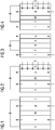
- FIG Figures 1 to 4 and 29 First exemplary configurations for an exemplary structure of general electrolysis cells and possible anode and cathode spaces are shown in FIG Figures 1 to 4 and 29 shown.
- An electrochemical reduction of, for example, CO 2 and / or CO takes place in an electrolysis cell, which usually consists of an anode and a cathode compartment.
- an electrolysis cell which usually consists of an anode and a cathode compartment.
- a described gas diffusion electrode can be used for each of these cell arrangements, for example as a cathode.
- membranes M for separating catholyte and anolyte shown but which can also be supplemented or replaced by diaphragms, for example.
- An example is the cathode compartment II in Figure 1 designed in such a way that a catholyte is fed in from below, which leaves the cathode compartment II towards the top.
- the catholyte can also be fed in from above, as is the case with falling film electrodes, for example.
- CO 2 and / or CO can be supplied via the gas diffusion electrode K.
- a substance is oxidized in the anode compartment I, which is supplied from below, for example with an anolyte, and the anolyte with the product the oxidation then leaves the anode compartment.
- This 2-chamber structure differs from the 3-chamber structure in Figure 2 to the effect that a reaction gas such as carbon dioxide or CO can be conveyed through a porous gas diffusion electrode as the cathode into the cathode space II for reduction.
- a reaction gas such as carbon dioxide or CO
- a porous gas diffusion electrode as the cathode into the cathode space II for reduction.
- a porous anode are also conceivable.
- the rooms I and II are separated by a membrane M.
- the Figure 3 a porous cathode K and a porous anode A directly on the membrane M, whereby the anode compartment I is separated from the cathode compartment II.
- the structure in Figure 4 corresponds to a hybrid form from the structure Figure 2 and the structure Figure 3 , a structure with a gas diffusion electrode being provided on the catholyte side, as in FIG Figure 2 shown, whereas on the anolyte side a structure as in Figure 3 is provided.
- a structure with a gas diffusion electrode being provided on the catholyte side, as in FIG Figure 2 shown, whereas on the anolyte side a structure as in Figure 3 is provided.
- mixed forms or other configurations of the electrode spaces shown by way of example are also conceivable.
- Embodiments without a membrane are also conceivable.
- the cathode-side electrolyte and the anode-side electrolyte can thus be identical, and the electrolysis cell / electrolysis unit can do without a membrane. Sufficient gas separation can then be achieved, for example, by appropriate construction of the electrolytic cell.
- the electrolytic cell in such embodiments has a membrane and / or a diaphragm or several membranes and / or diaphragms, for example 2, 3, 4, 5, 6 or more membranes and / or diaphragms, which are the same or different can, but this is possibly associated with additional effort in terms of the membrane as well as the applied voltage.
- the catholyte and anolyte can optionally be mixed again outside the electrolysis cell.
- Figures 1 to 4 are schematic representations.
- the electrolytic cells off Figures 1 to 4 can also be combined to form mixed variants.
- the anode compartment can be used as a PEM half-cell, as in FIG Figure 3
- the cathode compartment consists of a half-cell that contains a certain volume of electrolyte between the membrane and the electrode, as in Figure 1 shown.
- the electrolytic cell according to the invention then also one like in Fig. 29 may have the structure shown.
- the CO 2 can then diffuse through the gas diffusion electrode and reach the catholyte.
- the distance between the electrode and the membrane and / or diaphragm is very small or 0 if the membrane and / or the diaphragm is made porous and includes a supply of the electrolyte.
- the membrane and / or the diaphragm can also have a multilayer design so that separate feeds of anolyte and catholyte are made possible.
- separation effects can be achieved, for example, through the hydrophobicity of intermediate layers and / or a corresponding adjustment of the prevailing capillary forces. Conductivity can still be guaranteed if conductive groups are integrated in such separating layers.
- the membrane and / or the diaphragm can be an ion-conducting membrane and / or an ion-conducting diaphragm, or a separator which only effects mechanical separation and is permeable to cations and anions.
- the electrode is a gas diffusion electrode that enables a three-phase electrode to be built up.
- a gas can be fed from behind to the electrically active front side of the electrode in order to carry out the electrochemical reaction there.
- the gas diffusion electrode can only flow behind, ie a gas such as CO 2 and / or CO is led past the rear of the gas diffusion electrode in relation to the electrolyte, the gas then being able to penetrate through the pores of the gas diffusion electrode and the product being carried away at the rear can. It was found that even though a gas such as CO 2 does not "bubble" through the electrolyte, similarly high Faraday efficiencies (FE) can be found on products.
- FE Faraday efficiencies
- the gas flow when flowing behind is preferably also the reverse of the flow of the electrolyte, so that any liquid that may have been forced through is transported away can be.
- a gap between the gas diffusion electrode and the membrane is advantageous as an electrolyte reservoir.
- the supply of a gas can also be used in other ways for the in Figure 3 accomplish shown gas diffusion electrode, for example when supplying CO 2 . Because the gas, for example CO 2 , is passed through the electrode in a targeted manner, the reduction products can in turn be quickly discharged.
- the electrolytic cell has a membrane and / or a diaphragm which separates the cathode compartment and the anode compartment of the electrolytic cell in order to prevent the electrolytes from mixing.
- the membrane and / or the diaphragm is not particularly limited here, provided that it separates the cathode compartment and the anode compartment. In particular, it essentially prevents the gases produced at the cathode and / or anode from flowing over to the anode or cathode compartment.
- a preferred membrane is an ion exchange membrane, for example based on polymers.
- a preferred material of an ion exchange membrane is a sulfonated tetrafluoroethylene polymer such as Nafion®, for example Nafion® 115.
- a sulfonated tetrafluoroethylene polymer such as Nafion®, for example Nafion® 115.
- ceramic membranes can also be used, for example those in EP 1685892 A1 polymers mentioned and / or loaded with zirconium oxide, for example polysulfones.
- At least one membrane and / or at least one diaphragm in particular at least one anion exchange membrane (eg Tokuyama A201) and / or an anion exchange diaphragm, is not in contact with the anode.
- at least one further membrane and / or another diaphragm is provided between an anion exchange membrane and / or an anion exchange diaphragm and the anode, for example a cation exchange membrane and / or a cation exchange diaphragm, e.g. a Nafion®-based membrane, an electrolyte spar is then preferably provided in between here.
- the electrolytic cell according to the invention comprises 2 or more, e.g. 3, 4, 5, 6 or more membranes and / or diaphragms, with electrolyte spaces being provided between the various membranes and / or diaphragms and / or the membranes and / or diaphragms and the electrodes could be.
- the electrolysis cell according to the invention comprises at least one anion exchange membrane and / or one anion exchange diaphragm and at least one cation exchange membrane and / or one cation exchange diaphragm.
- the cation exchange membrane and / or the cation exchange diaphragm is in direct contact with the anode.
- an anion exchange membrane and / or an anion exchange diaphragm is in direct contact with the gas diffusion electrode according to the invention, which is connected as a cathode.
- An ionic connection of the GDE to an anion exchange membrane and / or an anion exchange diaphragm in a zero-gap arrangement can be ensured by using anion transport resins or ionomers. This step is advantageous for this mode of operation, since otherwise increased salt formation can be observed in the area of the boundary layer between GDE and anion exchange membrane, which can ultimately lead to complete isolation of the GDE.
- the material of the anode is not particularly limited and depends primarily on the desired reaction.
- exemplary anode materials include platinum or platinum alloys, palladium or palladium alloys, and vitreous carbon.
- Other anode materials are also conductive oxides such as doped or undoped TiO 2 , indium tin oxide (ITO), fluorine-doped tin oxide (FTO), aluminum-doped zinc oxide (AZO), iridium oxide, etc. If necessary, these catalytically active compounds can only be used in thin-film technology be applied superficially, for example on a titanium and / or carbon carrier.
- FIGS. 11 to 14 For the use of gas diffusion electrodes produced with ion exchange material, in particular with anion exchange resin and / or ionomer, the in FIGS. 11 to 14 Operating modes shown are possible, with diaphragms also being able to be provided here, in accordance with certain embodiments, instead of membranes.
- FIGs 11-14 In principle, two cell variants are shown for electrolysis cells: All cell variants use a GDE all-round catalyst with a single-layer structure, e.g. rolled onto a mesh, which was manufactured or impregnated with an anion exchange resin or ionomer as the anion exchange material and which is in direct contact with the AEM. In all cases, gaseous CO 2 is fed in from the rear of the GDE without a complete passage, which can also be seen as a flow by variant. In the cells shown, as well as generally in a reduction method according to the invention, a gas such as CO 2 and / or CO can be humidified before it reaches the GDE.
- a gas such as CO 2 and / or CO can be humidified before it reaches the GDE.
- anode When designing the anode, it is advantageous to avoid direct contact with an anion exchange membrane M1 because of observed stability problems. This applies to both the CCM execution in Fig. 14 , in which the anode catalyst, for example an IrOx catalyst, is pressed directly into the membrane M2, as well as for the use of a dimensionally stable anode A1, which can consist, for example, of an IrOx-coated expanded titanium metal.
- the gap between the anode and the GDE (cathode) should advantageously be as small as possible in order to achieve the highest possible efficiency of the system.
- the operating mode shown describes the diffusion operation of the gas diffusion electrode, whereby gaseous starting materials (here CO 2 ) and products P can be provided via the rear side of the electrode without these passing through the electrode.
- the gas pressure used should advantageously be selected as a function of the "bubble point" (eg range from 1-50 mbar) of the GDE electrode so that no gas can pass through.
- An advantage of this mode of operation is a higher conversion of the CO 2 used in contrast to the flow-through variant.
- the gas diffusion electrode described is particularly suitable for this cell operation.
- the manufacturing technique described can represent the basis for the production of electrodes on a larger scale, which can achieve current densities> 200 mA / cm 2 depending on the mode of operation.
- all previously known methods for producing ethylene-selective Cu electrodes are not suitable for scale-up or are not dimensionally stable, but so are other electrolysis cells for reducing CO 2 and / or CO.
- the use of ion exchange material, for example resins, in the gas diffusion electrode GDE enables a long-term stable electrolysis operation of a catalyst-based GDE in the in Figs. 1 to 4 and 11 to 14 Cell arrangements shown at high current densities in saline electrolytes.
- the anode reaction in the electrolytic cell according to the invention is by no means restricted to oxygen production. Further examples are the formation of peroxodisulfate or the production of chlorine. Avoiding salt excretion is particularly important in the production of chlorine, since, for example, NaHCO 3 is one of the more sparingly soluble carbonates and represents the outlet channel for the sodium ions as exemplary cations of electrolyte 45. Concentrated solutions close to the saturation limit are therefore advantageous for the conductivity of the electrolyte and for further processing (e.g.
- the anion exchange material can cause the sodium ions to diffuse too much into the gas diffusion electrode prevent. This is particularly important for operation at high current densities and high operating temperatures, in order to more easily transport away the anions formed and to counteract increased mobility of cations, for example sodium ions.
- the electrolytic cells shown in FIG Figures 11-14 can also be combined to form mixed variants.
- the anode compartment can again be designed as a PEM half-cell, while the cathode compartment can consist of a half-cell that contains a certain electrolyte volume between the membrane M, M1, M2 and the electrode.
- the distance between the electrode and the membrane M, M1, M2 is very small or 0 if the membrane is designed to be porous and contains a supply of the electrolyte.
- the membranes M, M1, M2 can also have a multilayer design, so that separate feeds of anolyte and catholyte are made possible.
- Separation effects can be achieved, for example in the case of aqueous electrolytes, for example through the hydrophobicity of intermediate layers. Conductivity can nevertheless be ensured if, for example, ion-conductive groups are integrated into such separating layers.
- the membrane M, M1, M2 can be an ion-conducting membrane or a separator which only effects mechanical separation.
- Yet another aspect of the present invention relates to an electrolysis system comprising the electrolysis cell according to the invention.
- FIG Figure 5 an example of an electrolysis is shown in which carbon dioxide is reduced on the cathode side and water is oxidized on the anode A side, although other reactions can also take place, for example on the anode side.
- a reaction of chloride to chlorine, bromide to bromine, sulfate to peroxodisulfate (with or without evolution of gas), etc. could take place on the anode side.
- Platinum or iridium oxide on a titanium carrier is suitable as anode A, for example, and an electrode for reducing CO 2 , for example based on Cu, is suitable as cathode K.
- the two electrode spaces of the electrolytic cell are separated by a membrane M, for example made of Nafion®.
- the integration of the cell in a system with anolyte circuit 10 and catholyte circuit 20 is shown in FIG Figure 5 shown schematically.
- water with electrolyte additives is fed into an electrolyte storage container 12 via an inlet 11.
- water is supplied in addition to or instead of the inlet 11 at another point of the anolyte circuit 10, since according to FIG Figure 5 the electrolyte reservoir 12 is also used for gas separation.
- the water is pumped from the electrolyte reservoir 12 by means of the pump 13 into the anode space, where it is oxidized.
- the product is then pumped back into the electrolyte storage container 12, where it can be discharged into the product gas container 14.
- the product gas can be withdrawn from the product gas container 14 via a product gas outlet 15.
- the product gas can also be separated off at another point, for example also in the anode compartment. This results in an anolyte circuit 10, since the electrolyte is circulated on the anode side.
- carbon dioxide is introduced into an electrolyte storage container 21 in the catholyte circuit 20 via a CO 2 inlet 22, where it is, for example, physically dissolved.
- This solution is brought into the cathode compartment by means of a pump 23, where the carbon dioxide at the cathode K is reduced.
- An optional further pump 24 then pumps the solution obtained at the cathode K further to a container for gas separation 25, where a product gas can be discharged into a product gas container 26. Via a product gas outlet 27, the product gas can be taken from the product gas container 26.
- the electrolyte is in turn pumped from the tank for gas separation back to the electrolyte storage tank 21, where carbon dioxide can be added again.
- a catholyte circuit 20 is given, with the individual device components of the catholyte circuit 20 also being able to be arranged differently, for example in that the gas separation already takes place in the cathode compartment.
- the gas separation and the gas saturation are preferably carried out separately, ie the electrolyte is saturated with CO 2 in one of the containers and then pumped through the cathode space as a solution without gas bubbles.
- the gas that emerges from the cathode compartment can then, according to certain embodiments, consist to a predominant part of product gas, since CO 2 itself can remain dissolved and / or because it was consumed and thus the concentration in the electrolyte is somewhat lower.
- the electrolysis takes place in Figure 5 by adding current via a current source, not shown.
- valves 30 can optionally be introduced in the anolyte circuit 10 and catholyte circuit 20.
- valves 30 are shown in the figure before the inlet into the electrolytic cell, but can also be provided, for example, after the outlet of the electrolytic cell and / or at other points in the anolyte or catholyte circuit. Also, for example, a valve 30 in the anolyte circuit can be located in front of the inlet into the electrolytic cell, while the valve in the catholyte circuit is located behind the electrolytic cell, or vice versa.
- FIG Figure 6 An abstract illustration of an exemplary device in an electrolysis system is shown in FIG Figure 6 shown.
- the device in Figure 6 corresponds to that of Figure 5 , the addition of the carbon dioxide not being introduced into an electrolyte storage container 21 via a CO 2 inlet 22, but directly via the cathode K, which is designed here as the gas diffusion electrode according to the invention.
- the CO 2 can be supplied, for example, by flowing behind or through the gas diffusion electrode.
- FIG Figures 30 and 31 Further exemplary devices according to the invention with gas diffusion electrodes through which flow and behind flow are used as cathodes are shown in FIG Figures 30 and 31 shown, with the carbon dioxide being guided in countercurrent here.
- a diaphragm D is also provided instead of a membrane.
- composition of a liquid or solution for example an electrolyte solution, which is fed to the electrolysis device, is not particularly limited and can include all possible liquids or solvents, such as water, in which additional electrolytes such as conductive salts, ionic liquids, substances for electrolytic conversion such as carbon dioxide, which can for example be dissolved in water, additives to improve the solubility and / or the wetting behavior, defoamers, etc. can be included.
- carbon dioxide for example, can be included in the catholyte.
- the liquids or solvents possibly additional electrolytes such as conductive salts, ionic liquids, substances for electrolytic conversion, additives to improve solubility and / or wetting behavior, defoamers, etc. can be present in at least one electrode space or in both electrode spaces. Two or more of the substances mentioned or mixtures thereof can also be included in each case. According to the invention, these are not particularly restricted and can be used on the anode side and / or cathode side.
- the electrolysis cell according to the invention or the electrolysis system according to the invention can be used, for example, in an electrolysis of carbon dioxide and / or CO.
- the present invention relates to a method for the electrolysis of CO 2 and / or CO, the electrolysis cell according to the invention or the electrolysis system according to the invention being used.
- the method takes place at a temperature of 40 ° C. or more, for example 50 ° C. or more.
- an aqueous electrolyte is used.
- the electrochemical reduction of CO 2 and / or CO can take place in an electrolysis cell, which usually consists of an anode and a cathode compartment.
- the anode compartment and cathode compartment are typically kept separated from one another by at least one ion-selective membrane or a diaphragm.
- Examples of possible cell arrangements of electrolysis cells for the electrolysis of CO 2 and / or CO according to the invention are shown, which are also described in detail above.
- the electrolysis process according to the invention can be carried out with each of these cell arrangements.
- the electrochemical reduction of CO 2 and / or CO takes place in the flow-by mode.
- the present invention is directed to the use of the electrolysis cell according to the invention in the electrolysis of CO 2 and / or CO.
- the described gas diffusion electrode can be produced, so that the corresponding features of the gas diffusion electrode can also be used in this production method.
- the proportions by weight of the constituents during production can also be suitably set in accordance with the proportions by weight of the gas diffusion electrode and the corresponding materials can be used as metal M, ion exchange material and binder.
- the promoters described above can also be added appropriately.
- the production of the first and second mixtures or the first mixture is not particularly restricted and can be carried out in a suitable manner, for example by stirring, dispersing, etc.
- the first mixture can also contain 0% by weight of binder, i.e. no binder, since binder from the second mixture can be pressed into the first layer formed from the first mixture and thus also the first layer when it is rolled on may have a binder content of, for example, at least 0.1% by weight, for example 0.5% by weight. According to certain embodiments, however, when 2 or more mixtures are applied, the first mixture contains binders.
- the binder comprises a polymer, for example a hydrophilic and / or hydrophobic polymer, for example a hydrophobic polymer, e.g. PTFE.
- a polymer for example a hydrophilic and / or hydrophobic polymer, for example a hydrophobic polymer, e.g. PTFE.
- the metal M for the production of the mixture is in the form of particles or catalyst particles which, for example, have a uniform particle size between 1 and 80 ⁇ m, preferably 10 to 50 ⁇ m, more preferably between 30 and 50 ⁇ m.
- the particle size can be determined, for example, microscopically by means of image analysis, laser diffraction and / or dynamic light scattering.
- the catalyst particles have a high degree of purity without traces of foreign metal. A high selectivity and long-term stability can be achieved through suitable structuring, if necessary with the aid of the promoters, as described above.
- the pores and / or channels, i.e. the hydrophobic and hydrophilic pores and / or channels, of the GDE can be specifically set for the passage of gas and / or by suitable setting of the particle sizes of metal M, ion exchange material and binder and, if necessary, further additives such as promoters or electrolyte and thus for the catalytic reaction.
- first and further mixture (s) is not particularly restricted and can take place, for example, by sprinkling on, sifting on, squeegeeing, etc.
- the rolling is not particularly limited and can be done appropriately.
- the respective mixtures can be moistened for this purpose, for example to a moisture content of 20% by weight or less, for example 5, 4, 3, 2, 1 or less% by weight, based on the respective mixture.
- Rolling the mixture or mass (particles) into the structure of the carrier, for example a network structure is according to certain Embodiments expressly desired in order to ensure a high mechanical stability of the electrode. This is not the case with a two-stage process, here the pre-extruded film only rests on the mesh.
- the mixtures for the layers are applied individually to the carrier and then rolled on as a whole in order to achieve better adhesion between the layers.
- the mechanical stress on the binder, for example plastic particles, by the rolling process leads to crosslinking of the powder through the formation of binder channels, for example PTFE fibrils. Achieving this state is particularly important in order to guarantee suitable porosity and mechanical stability of the electrode.
- the hydrophobicity can be adjusted via the respective content of polymer and ion exchange material, e.g. ion exchange resin, or via the physical properties of the metal M or the catalyst powder, for example as discussed above in connection with the gas diffusion electrode according to the invention.
- the degree of fibrillation of the binder correlates directly with the applied shear rate, since the binder, for example a polymer, behaves as a shear-thinning (pseudoplastic) fluid when it is rolled out. After extrusion, the layer obtained has an elastic character due to the fibrillation. This structural change is irreversible, so that this effect can no longer be subsequently increased by further rolling, but the layer is damaged by the elastic behavior when further shear forces are applied. Particularly strong fibrillation can disadvantageously lead to the electrode curling up on the layer side, so that excessively high binder contents should be avoided.
- Temperature control of the rollers during rolling can also support the flow process.
- the preferred temperature range of the rollers is between room temperature, e.g. 20-25 ° C, and 200 ° C, e.g. 20-200 ° C, preferably between 40 and 100 ° C.
- the rolling or calendering is carried out at a roller speed of between 0.3 and 3 rpm, preferably 0.5-2 rpm.
- the flow rate or feed rate (the GDE in length per time, for example during calendering) Q is in the range from 0.04 to 0.4 m / min, preferably 0.07 to 0.3 m / min.
- the water content during rolling corresponds at most to the humidity of the room, for example.
- the content of water and solvents during rolling is less than 5% by weight, preferably less than 1% by weight, and for example also 0% by weight.
- the carrier is a mesh, for example comprising the metal M, with a mesh size w of 0.3 mm ⁇ w ⁇ 2.0 mm, preferably 0.5 mm ⁇ w ⁇ 1.4 mm and a wire diameter x of 0 , 05 mm ⁇ x ⁇ 0.5 mm, preferably 0.1 mm x x 0.25 mm.
- the bed height y of the first mixture on the carrier during application is in the range of 0.3 mm ⁇ y ⁇ 3.0 mm, preferably 0.5 mm y 2.0 mm.
- each layer can have a corresponding bed height y, but the bed heights of all layers preferably add up to not more than 3.0 mm, preferably not more than 2 mm, more preferably not more than 1.5 mm.
- the rolling takes place by means of a calender.
- the method according to the invention can thus be carried out by a calendering process as shown schematically in Figure 8 is shown and described above.
- the rolling process itself is characterized in that a reservoir of material is formed in front of the roller.
- the gap width when rolling on H 0 is the height of the carrier + 40% to 50% of the total bed height Hf of the mixtures of the various layers, for example the bed height y of the first mixture, if only this is used, or almost corresponds to the thickness of the net + 0.1-0.2mm delivery.
- the ratio between the exit thickness H and the gap width H 0 should preferably be in the range of 1.2.
- a dry calendering process is used in the production process according to the invention, in which a mixture of binder, e.g. a cold-flowing polymer, e.g. preferably PTFE, the respective powder of the metal M or the catalyst powder and possibly the powder of the ion exchange material is produced, e.g. in an intensive mixing device or on a laboratory scale with a knife mill (IKA).
- the mixing procedure can for example follow the following procedure: 30sec grinding / mixing and 15sec break for a total of 6 minutes, based on the knife mill with a total load of 50g.
- the mixed powder will have a slightly sticky consistency after mixing.
- the mixing time can also vary until this state is reached.
- the powder mixture obtained can then be sprinkled or sieved in a suitable bulk thickness onto the carrier, e.g. a metal net, e.g. with a mesh size of> 0.5mm ⁇ 1.0mm and a wire diameter of 0.1-0.25 mm. So that the powder does not trickle through the net, the back of the net can be sealed with a film.
- the prepared layer can then be compacted with the help of a two-roller roller device (calendar).
- a two-layer structure can be used for a GDE with a solid anion exchange resin.
- a hydrophobic base layer can be produced as a second layer, e.g. with 15% by weight PTFE and 85% by weight powder of the metal M, e.g. Cu or Ag, on the carrier as a current distributor, on which a second layer with the corresponding exchange resin is applied becomes.
- the extruded base layer should preferably have a thickness of 100-500 ⁇ m, preferably 250-400 ⁇ m.
- the base layer can be characterized, for example, by a very high conductivity, for example 7 mOhm / cm, and have a high porosity of, for example, 50-70% and a hydrophobic character.
- the base layer can itself be catalytically active in the area of the overlap zone to the catalyst layer, the first layer. It serves to improve the electrical connection of the electrocatalyst over a large area and, due to its high porosity, can improve the availability of gas, for example the availability of CO 2. With the help of this method, according to certain embodiments, the required amount of catalyst can be reduced by a factor of 20-30.
- a corresponding electrocatalyst or metal M / binder for example a PTFE / ion exchanger mixture
- a corresponding electrocatalyst or metal M / binder for example a PTFE / ion exchanger mixture
- the preparation can also begin with the production of the catalyst layer and the application of a binder, for example PTFE, to the back of the mesh can be carried out subsequently.
- the binder used, eg PTFE can also be pretreated beforehand in a knife mill, if necessary, in order to achieve fiber formation.
- An exemplary production of the gas diffusion electrode with binder, Eg P, TFE based diffusion barrier is based on several layers, which are not to be considered isolated from one another, but rather have as wide an overlap zone as possible in the border areas, for example 1-20 ⁇ m.
- the total layer thickness of the gas diffusion electrode can be in the range of 200-800 ⁇ m, for example 450-600 ⁇ m.
- the two-layer structure enables the use of hydrophilic ion exchange resins in the catalyst layer without flooding the gas transport pores.
- FIG. 9 An exemplary schematic structure of a two-layer GDE is shown in Figure 9 shown, with a hydrophobic layer 47 comprising a mixture 43 of metal M and binder, for example Cu and PTFE, being applied to the carrier 44 as a current distributor, and a hydrophilic layer 46 as a first layer comprising catalyst particles 40 of the metal M, binder particles 41, for example PTFE and ion exchange resin 42. Electrolyte 45 arrives at the hydrophilic layer 46, while the reaction gas, for example CO 2 , arrives at the hydrophobic layer.
- a hydrophobic layer 47 comprising a mixture 43 of metal M and binder, for example Cu and PTFE
- Electrolyte 45 arrives at the hydrophilic layer 46
- the reaction gas for example CO 2
- the content of polar ion exchange polymer should be greatly reduced in order not to adversely affect the gas transport properties or to prevent the electrolyte from flowing through.
- An existing GDE for example a commercially available silver gas diffusion electrode from the area of chlor-alkali electrolysis (Oxygen Depolarized Cathode, ODC), comprising metal M and binders, e.g. PTFE, can also be post-treated, for example by directing it with a microemulsion of ion exchange resin or ionomer is impregnated, for example in such a way that essentially exclusively the surface or a region of the electrode close to the surface has hydrophilic properties.
- an existing GDE can be modified with a potential-free diffusion barrier.
- Fig. 10 shows this schematically, wherein a hydrophilic coating and / or layer 46 can be formed on the hydrophobic layer 47 by spraying.
- a gas diffusion electrode can be prepared on the basis of a GDL structure, for example Freudenberg C2, Sigracet 25 BC.
- a catalyst suspension composed of nanoparticles and ionomer in alcohol can be used to prepare the electrode.
- Example 1 Production of a single-layer gas diffusion electrode (GDE) from powdered cation exchange resin and catalyst powder (comparative example)
- the respective gas diffusion electrode (GDE) with an active area of 3.3 cm 2 was used as cathode in the flow cell, the gas supply rate of carbon dioxide on the cathode side was 50 ml / min, and the electrolyte flow on both sides was 130 ml / min.
- the anode was iridium oxide on a titanium support with an active area of 10 cm 2 .
- the catholyte was a 1M KHCO 3 solution with KHCO 3 in a 1M concentration, and the anolyte was 1M KHCO 3 , each in deionized water (18 M ⁇ ), each in an amount of 100 mL, and the temperature was 25 ° C.
- 0.5MK 2 SO 4 was tried as the catholyte and 2.5M KOH as the anolyte.
- a stable electrolysis operation could not be guaranteed due to the high electrolyte permeability of the gas diffusion electrode.
- Example 2 Production of a two-layer GDE from a hydrophobic base layer and a hydrophilic exchange layer with powdered cation exchange resin and catalyst powder (comparative example)
- the mixture containing ion exchange resin from exemplary embodiment 1 is sieved onto the prepared base layer using a 0.2 mm template and calibrated using a doctor blade.
- the double layer is rolled into an electrode using a 2-roll calender with a gap width of 0.5 mm.
- the cell structure for investigating the product selectivity corresponded to that of Example 1, except that the GDE produced accordingly from Example 2 was used as the cathode.
- Example 3 Production of a single-layer GDE from a base layer and a sprayed-on exchange layer with a cation exchange resin suspension (comparative example)
- a 20% strength by weight micro-dispersion of IRA 900 ion exchange resin (see Example 1) or the ionomer Tokuyama AS4 (Tokuyama) is sprayed onto the calendered gas diffusion electrode so that a thin film is formed. A total of 10 ml was sprayed onto 40 cm 2.
- the cell structure for investigating the product selectivity corresponded to that of Example 1, except that the GDE produced accordingly from Example 3 was used as the cathode.
- Fig. 15 shows the results of a pure copper GDE as a comparison electrode, which was not sprayed with the respective dispersion
- Fig. 16 the results of the GDE impregnated with Tokuyama AS4, and
- Fig. 17 the results of the GDE impregnated with IRA 900.
- the figures indicate the Faraday efficiency (FE) as a function of the current density J.
- the comparison of the experimental data shows that the use of ion exchange resins or ionomers does not have any negative influence on the ethylene selectivity. At higher current densities, the formation of hydrogen is also slightly suppressed compared to the pure copper catalyst, s.
- Figures 16 and 17 in contrast to Fig. 15 .
- Example 4 Coating of a hydrophobic base layer with the acidic cation exchange ionomer poly (4-styrenesulfonic acid) (comparative example)
- 60 mg of detritic copper catalyst and 60 mg of an 18% by weight suspension of the cation exchange ionomer poly (4-styrenesulfonic acid in water are weighed in and diluted with 2 ml of isopropanol, and the mixture is homogenized for 15 min in an ultrasonic bath applied to an already produced base layer (4cmx10cm, thickness 0.5 mm) of 15% by weight PTFE and 85% by weight copper powder with a particle diameter of the copper particles in the production of 100-150 ⁇ m and dried in an argon stream and the pouring process repeated 3 times.
- the electrode is dried in a stream of argon for 12 hours before use, and the thickness changed only insignificantly.
- the cell structure for investigating the product selectivity corresponded to that of Example 1, except that the GDE produced accordingly from Example 4 was used as the cathode.
- Fig. 18 shows the results with regard to the product selectivity that can be obtained with this electrode as a function of the current density.
- the Faraday efficiency for unwanted H 2 is around 45%.
- acidic ion exchangers are less suitable for the formation of CO and hydrocarbons. In structures with direct contact between an acidic Nafion membrane and the catalyst, little or no hydrocarbons or CO can usually be obtained, but only hydrogen is usually formed.
- 60 mg of dentritic copper catalyst powder and 120 mg of a 16.7% strength by weight microemulsion ( 20 g of IRA 900 (see Example 1) with 80 g of H 2 O, 20 g of isopropanol) are weighed into a 4 ml jar, diluted with 2 ml of isopropanol and the mixture is homogenized for 15 min in an ultrasonic bath.
- the dispersion produced is applied to an already produced base layer (4cmx10cm) of 15% by weight PTFE and 85% by weight copper powder with a particle diameter of 100-150 ⁇ m for the copper particles during production and dried in an argon stream and the pouring process repeated 3 times.
- the electrode is dried in a stream of argon for 12 hours before use.
- the cell structure for investigating the product selectivity corresponded to that of Example 1, except that the GDE produced accordingly from Example 5 was used as the cathode.
- Fig. 19 shows the results with regard to the product selectivity that can be obtained with this electrode as a function of the current density.
- the anion exchange resin suppresses the generation of hydrogen to an FE of about 20%.
- Methane is formed with an FE of around 5%.
- the formation of liquid products such as ethanol, propanol is intensified, as from the deviation from the sum of gaseous products from 100% can be seen.
- Example 6 Coating of a hydrophobic base layer with an anion exchanger ionomer with R 4 N + groups
- FUMA Tech AS4, n-propanol; FUMA Tech 60 mg of dendritic copper catalyst powder and 120 mg of a 5% by weight dispersion (FUMA Tech AS4, n-propanol; FUMA Tech) are weighed in and diluted with 2 ml of n-propanol and the mixture is homogenized for 15 min in an ultrasonic bath in a 4 ml snap-lid jar.
- the dispersion produced is applied to an already produced base layer (4cmx10cm) of 15% by weight PTFE and 85% by weight copper powder with a particle diameter of 100-150 ⁇ m for the copper particles during production and dried in an argon stream and the pouring process repeated 3 times.
- the electrode is dried in a stream of argon for 12 hours before use.
- the cell structure for investigating the product selectivity corresponded to that of Example 1, except that the GDE produced accordingly from Example 6 was used as the cathode.
- the cell structure for investigating the product selectivity corresponded to that of Example 1, except that the GDE produced accordingly from Example 6 was used as the cathode.
- Fig. 20 shows the results with regard to the product selectivity that can be obtained with this electrode as a function of the current density.
- the anion exchange ionomer suppresses the formation of hydrogen to an FE of about 10-20%.
- the formation of methane is completely suppressed.
- Example 7 Coating of a hydrophobic base layer with the acidic cation exchange ionomer (Nafion) (comparative example)
- 60 mg of copper catalyst powder and 60 mg of a 20% by weight dispersion (solvent: 34% by weight of water, remainder aliphatic alcohols, Dupont) (Nafion, Aldrich)) are weighed in and diluted with 2 ml of isopropanol and the mixture for Homogenized for 15 min in an ultrasonic bath.
- the dispersion produced is applied to an already produced base layer (4cmx10cm) of 15% by weight PTFE and 85% by weight copper powder with a particle diameter of 100-150 ⁇ m for the copper particles during production and dried in an argon stream and the pouring process repeated 3 times.
- the electrode is dried in a stream of argon for 12 hours before use.
- the cell structure for investigating the product selectivity corresponded to that of Example 1, except that the GDE produced accordingly from Example 7 was used as the cathode.
- Fig. 21 shows the results with regard to the product selectivity that can be obtained with this electrode as a function of the current density.
- the formation of methane is completely suppressed.
- Example 8 Reference experiment according to US 2016 / 0251766A1 for the production of CO
- Fig. 22 shows the tracking of the product Faraday efficiency of CO and H 2 over time at a constant current density of 50mA / cm 2 .
- Example 9 Coating of a hydrophobic base layer with an anion exchange ionomer Tokuyama AS4 and with the additional use of a Tokuyama AEM 207 membrane using a cell structure with a double membrane
- the GDE was produced according to Example 3 with Tokuyama AS4 as the anion exchange ionomer.
- the cell structure for investigating the product selectivity corresponded to that of Example 3 with the corresponding GDE with Tokuyama AS4, except that a Tokuyama AEM 207 membrane was additionally used, which was in direct contact with the GDE.
- the experimental setup corresponds to that in Fig. 13 shown.
- Fig. 23 shows the results with regard to the product selectivity that can be obtained with this electrode as a function of the current density.
- the anion exchange ionomer Tokuyama AS4 suppresses the undesired formation of hydrogen at increased current densities.
- the cell structure enables the Faraday efficiency for ethylene to be increased by a factor of 2 to 30%.
- the formation of methane is completely suppressed.
- the present invention relates to a method and an electrolysis system for the electrochemical utilization of carbon dioxide.
- Carbon dioxide (CO 2 ) can be introduced into an electrolytic cell and attached to a cathode using a gas diffusion electrode (GDE) on the cathode side.
- GDE gas diffusion electrode
- GDE are porous electrodes in which liquid, solid and gaseous phases are present and the electrically conductive catalyst catalyzes the electrochemical reaction between the liquid and the gaseous phase.
- catalyst-based gas diffusion electrodes are preferably used, which are known in a similar manner from large-scale chlor-alkali electrolysis.
- the catalyst-based gas diffusion electrode can on the one hand be in contact with a liquid, for example salt-containing, electrolyte, or it can be in direct contact with a separator membrane. In the latter case, ionic bonding of the catalyst particles to the membrane is advantageous, since the membrane can be used as a solid electrolyte in this mode of operation.
- ion exchange materials are integrated into the gas diffusion electrode, which preferably have functional groups such as quaternary ammonium groups and thus function as anion transporters.
- the introduction of ion exchange materials in powder form, for example exchange resins, for example anion exchange materials, into a catalyst-based gas diffusion electrode is a new method for widening the process window for the electrochemical reduction of CO 2 and / or CO.
- the modification offers advantages in particular from a current density> 150 mA / cm 2 , since the generation of hydrogen can be reduced. For example, increased Faraday efficiencies for CO or ethylene can be obtained.
- the method also offers the possibility of increasing the ionic conductivity of the gas diffusion electrode, whereby the formation of concentration gradients can be reduced.
- the method also offers the possibility of using a catalyst-based gas diffusion electrode within a membrane electrode assembly, in particular an MEA (Membrane Electrode Assembly) assembly.
- MEA Membrane Electrode Assembly
- gas diffusion electrodes based on catalyst powder can be produced, which can be used in a large-scale electrolyser application in the context of electrochemical CO 2 and which enable improved long-term stability of the electrolysis operation.
- ion exchange materials e.g. anion exchange materials, in particular anion exchange resins
- the gas diffusion electrode forms a low-energy path for dissipating the hydroxide and hydrogen carbonate anions that are formed, which at the same time can prevent the diffusion of mobile cations from the electrolyte due to the positive polymer backbone structure.
Landscapes
- Chemical & Material Sciences (AREA)
- Organic Chemistry (AREA)
- Engineering & Computer Science (AREA)
- Electrochemistry (AREA)
- Chemical Kinetics & Catalysis (AREA)
- Materials Engineering (AREA)
- Metallurgy (AREA)
- Inorganic Chemistry (AREA)
- Combustion & Propulsion (AREA)
- Analytical Chemistry (AREA)
- General Chemical & Material Sciences (AREA)
- Oil, Petroleum & Natural Gas (AREA)
- Electrodes For Compound Or Non-Metal Manufacture (AREA)
- Electrolytic Production Of Non-Metals, Compounds, Apparatuses Therefor (AREA)
- Catalysts (AREA)
Priority Applications (1)
| Application Number | Priority Date | Filing Date | Title |
|---|---|---|---|
| PL18714125T PL3583245T3 (pl) | 2017-03-13 | 2018-02-15 | Wytwarzanie dyfuzyjnych elektrod gazowych zawierających żywice transportujące jony do elektrochemicznej redukcji CO2 do produktów chemicznych |
Applications Claiming Priority (2)
| Application Number | Priority Date | Filing Date | Title |
|---|---|---|---|
| DE102017204096.3A DE102017204096A1 (de) | 2017-03-13 | 2017-03-13 | Herstellung von Gasdiffusionselektroden mit Ionentransport-Harzen zur elektrochemischen Reduktion von CO2 zu chemischen Wertstoffen |
| PCT/EP2018/053768 WO2018166739A1 (de) | 2017-03-13 | 2018-02-15 | Herstellung von gasdiffusionselektroden mit ionentransport-harzen zur elektrochemischen reduktion von co2 zu chemischen wertstoffen |
Publications (2)
| Publication Number | Publication Date |
|---|---|
| EP3583245A1 EP3583245A1 (de) | 2019-12-25 |
| EP3583245B1 true EP3583245B1 (de) | 2021-05-19 |
Family
ID=61827667
Family Applications (1)
| Application Number | Title | Priority Date | Filing Date |
|---|---|---|---|
| EP18714125.4A Active EP3583245B1 (de) | 2017-03-13 | 2018-02-15 | Herstellung von gasdiffusionselektroden mit ionentransport-harzen zur elektrochemischen reduktion von co2 zu chemischen wertstoffen |
Country Status (10)
| Country | Link |
|---|---|
| US (1) | US12606920B2 (da) |
| EP (1) | EP3583245B1 (da) |
| CN (1) | CN110402303B (da) |
| AU (1) | AU2018233505B2 (da) |
| DE (1) | DE102017204096A1 (da) |
| DK (1) | DK3583245T3 (da) |
| ES (1) | ES2883104T3 (da) |
| PL (1) | PL3583245T3 (da) |
| SA (1) | SA519410059B1 (da) |
| WO (1) | WO2018166739A1 (da) |
Families Citing this family (28)
| Publication number | Priority date | Publication date | Assignee | Title |
|---|---|---|---|---|
| JP2018090838A (ja) * | 2016-11-30 | 2018-06-14 | 昭和シェル石油株式会社 | 二酸化炭素還元装置 |
| DE102017204096A1 (de) | 2017-03-13 | 2018-09-13 | Siemens Aktiengesellschaft | Herstellung von Gasdiffusionselektroden mit Ionentransport-Harzen zur elektrochemischen Reduktion von CO2 zu chemischen Wertstoffen |
| EP3418429A1 (de) * | 2017-06-21 | 2018-12-26 | Covestro Deutschland AG | Gasdiffusionselektrode zur reduktion von kohlendioxid |
| DE102018210458A1 (de) * | 2018-06-27 | 2020-01-02 | Siemens Aktiengesellschaft | Gasdiffusionselektrode zur Kohlendioxid-Verwertung, Verfahren zu deren Herstellung sowie Elektrolysezelle mit Gasdiffusionselektrode |
| US20220136117A1 (en) * | 2019-02-18 | 2022-05-05 | Skyre, Inc. | Method and system for recovering hydrogen and converting a carbon compound to a valualbe organic product |
| EP3725914A1 (de) | 2019-04-18 | 2020-10-21 | Siemens Aktiengesellschaft | Verfahren und vorrichtung zur elektrochemischen nutzung von kohlenstoffdioxid |
| EP3730673A1 (en) * | 2019-04-24 | 2020-10-28 | Université Paris Diderot Paris 7 | Electrochemical system for the selective reduction of carbon monoxide into methanol |
| EP3805429A1 (de) * | 2019-10-08 | 2021-04-14 | Covestro Deutschland AG | Verfahren und elektrolysevorrichtung zur herstellung von chlor, kohlenmonoxid und gegebenenfalls wasserstoff |
| CN111074294B (zh) * | 2019-12-12 | 2021-12-14 | 中国科学技术大学 | 一种铜合金材料电催化二氧化碳制备含碳化合物的方法 |
| JP7198238B2 (ja) * | 2020-03-19 | 2022-12-28 | 株式会社東芝 | 二酸化炭素電解セル用電極触媒層、ならびにそれを具備する、電解セルおよび二酸化炭素電解用電解装置 |
| CN111495425B (zh) * | 2020-03-26 | 2023-06-09 | 东莞理工学院 | 聚苯胺-金复合材料、制备及其用途 |
| US20230151501A1 (en) * | 2020-04-17 | 2023-05-18 | The University Of British Columbia | Electrolytic conversion of carbon-containing ions using porous metal electrodes |
| EP4162099A2 (en) * | 2020-06-09 | 2023-04-12 | Twelve Benefit Corporation | System and method for high concentration of multielectron products or co in electrolyzer output |
| CN116096477A (zh) * | 2020-07-14 | 2023-05-09 | 伊利诺伊大学评议会 | 用于碳捕获和转化的系统和工艺 |
| WO2022013042A1 (en) * | 2020-07-14 | 2022-01-20 | Vito Nv | Carbon free gas diffusion electrode |
| US20220396887A1 (en) * | 2021-06-10 | 2022-12-15 | Massachusetts Institute Of Technology | Metal-organic framework on gas diffusion electrode |
| CN113564624B (zh) * | 2021-07-16 | 2022-12-02 | 华中科技大学 | 一种回收铅材料用于二氧化碳还原制甲酸盐的方法 |
| CA3227233A1 (en) * | 2021-07-27 | 2023-02-02 | Colin O'brien | Use of a porous recycling layer for co2 electroreduction to multicarbon products with high conversion efficiency |
| CN114232017B (zh) * | 2021-12-22 | 2023-02-21 | 西北工业大学深圳研究院 | 一种硒化银纳米催化剂及其制备方法和应用 |
| US20230407495A1 (en) * | 2022-06-14 | 2023-12-21 | Giner, Inc. | Gas diffusion electrode suitable for use in carbon dioxide electrolyzer and membrane electrode assembly including said gas diffusion electrode |
| CN115584522A (zh) * | 2022-11-07 | 2023-01-10 | 天津大学 | 三维多孔电极及制备方法和酸性电催化二氧化碳还原制甲酸的应用 |
| CN116924473B (zh) * | 2023-04-21 | 2025-09-16 | 北部湾大学 | 一种含纳米棒状钒酸锰和钒酸钠的复合材料、制备方法及其制备的自支撑膜负极 |
| CN116425315B (zh) * | 2023-05-25 | 2024-07-16 | 中交第三公路工程局有限公司 | 一种基于电动力学强化脱氮的人工湿地系统 |
| DE102023115862A1 (de) * | 2023-06-16 | 2024-12-19 | Fraunhofer-Gesellschaft zur Förderung der angewandten Forschung eingetragener Verein | Gasdiffusionselektrode und ihre Verwendung |
| CN121729448A (zh) * | 2023-08-21 | 2026-03-24 | 易沃绿公司 | 膜电极组件 |
| EP4512934A1 (en) * | 2023-08-22 | 2025-02-26 | Siemens Energy Global GmbH & Co. KG | Novel membrane electrode assembly design for c2h4 selective cem-type co2-electrolyzers |
| GB2641222A (en) * | 2024-05-17 | 2025-11-26 | Johnson Matthey Plc | Electrocatalyst layer |
| DE102024209634A1 (de) * | 2024-10-02 | 2026-04-02 | Robert Bosch Gesellschaft mit beschränkter Haftung | Verfahren und Abscheider zum Abscheiden eines Zielgases aus einem Stoffgemisch |
Family Cites Families (34)
| Publication number | Priority date | Publication date | Assignee | Title |
|---|---|---|---|---|
| DE3303779A1 (de) | 1983-02-04 | 1984-08-16 | Hoechst Ag, 6230 Frankfurt | Verfahren zur herstellung eines katalytisch wirksamen elektrodenmaterials fuer sauerstoffverzehr-elektroden |
| DE3710168A1 (de) | 1987-03-27 | 1988-10-13 | Varta Batterie | Verfahren zur herstellung einer kunststoffgebundenen gasdiffusionselektrode mit metallischen elektrokatalysatoren |
| DE3722019A1 (de) | 1987-07-03 | 1989-01-12 | Varta Batterie | Verfahren zur herstellung einer kunststoffgebundenen gasdiffusionselektrode, die einen manganoxidkatalysator der ueberwiegenden zusammensetzung mno(pfeil abwaerts)2(pfeil abwaerts)o(pfeil abwaerts)3(pfeil abwaerts)* x mn(pfeil abwaerts)5(pfeil abwaerts)o(pfeil abwaerts)8(pfeil abwaerts) enthaelt |
| JPH0693485A (ja) | 1992-09-10 | 1994-04-05 | Tanaka Kikinzoku Kogyo Kk | 二酸化炭素の還元方法 |
| US6074773A (en) * | 1998-03-06 | 2000-06-13 | Ballard Power Systems Inc. | Impregnation of microporous electrocatalyst particles for improving performance in an electrochemical fuel cell |
| AU4500500A (en) * | 1999-04-30 | 2000-11-17 | University Of Connecticut, The | Membranes, membrane electrode assemblies and fuel cells employing same, and process for preparing |
| DE10148599A1 (de) | 2001-10-02 | 2003-04-10 | Bayer Ag | Verfahren zur Herstellung von Gasdiffusionselektroden aus trockenen Pulvermischungen mittels Walzen |
| US20040157101A1 (en) * | 2003-02-11 | 2004-08-12 | Smedley Stuart I. | Fuel cell electrode assembly |
| DE10335184A1 (de) | 2003-07-30 | 2005-03-03 | Bayer Materialscience Ag | Elektrochemische Zelle |
| US7923172B2 (en) * | 2003-11-14 | 2011-04-12 | Basf Fuel Cell Gmbh | Structures for gas diffusion materials and methods for their fabrication |
| DE102005003612B3 (de) | 2005-01-26 | 2006-06-14 | Forschungszentrum Jülich GmbH | Verfahren zur Herstellung einer dünnen, gasdichten und Protonen leitenden Keramikschicht sowie Verwendung derselben |
| DE102005023615A1 (de) | 2005-05-21 | 2006-11-23 | Bayer Materialscience Ag | Verfahren zur Herstellung von Gasdiffusionselektroden |
| WO2009012154A2 (en) | 2007-07-13 | 2009-01-22 | University Of Southern California | Electrolysis of carbon dioxide in aqueous media to carbon monoxide and hydrogen for production of methanol |
| GB0814652D0 (en) * | 2008-08-11 | 2008-09-17 | Univ Surrey | Interface polymer |
| JP5488254B2 (ja) * | 2009-06-26 | 2014-05-14 | 日産自動車株式会社 | 燃料電池用親水性多孔質層、ガス拡散電極およびその製造方法、ならびに膜電極接合体 |
| WO2011013004A1 (en) * | 2009-07-31 | 2011-02-03 | Revolt Technology Ltd. | Metal-air battery with improved environmental stability |
| US9370773B2 (en) | 2010-07-04 | 2016-06-21 | Dioxide Materials, Inc. | Ion-conducting membranes |
| WO2016064440A1 (en) | 2014-10-21 | 2016-04-28 | Dioxide Materials | Electrolyzer and membranes |
| DE102010030203A1 (de) | 2010-06-17 | 2011-12-22 | Bayer Materialscience Ag | Gasdiffusionselektrode und Verfahren zu ihrer Herstellung |
| US10047446B2 (en) * | 2010-07-04 | 2018-08-14 | Dioxide Materials, Inc. | Method and system for electrochemical production of formic acid from carbon dioxide |
| DE102010031571A1 (de) | 2010-07-20 | 2012-01-26 | Bayer Materialscience Ag | Sauerstoffverzehrelektrode |
| DE102010042729A1 (de) | 2010-10-21 | 2012-04-26 | Bayer Materialscience Aktiengesellschaft | Sauerstoffverzehrkathode und Verfahren zu ihrer Herstellung |
| DE102010054643A1 (de) | 2010-12-15 | 2012-06-21 | Bayer Material Science Ag | Elektrolyseur mit spiralförmigem Einlaufschlauch |
| US20120171583A1 (en) * | 2010-12-30 | 2012-07-05 | Liquid Light, Inc. | Gas phase electrochemical reduction of carbon dioxide |
| WO2013134078A1 (en) | 2012-03-03 | 2013-09-12 | Viceroy Chemical Inc. | Electrolytic cell including a three-phase interface to react carbon-based gases in an aqueous electrolyte |
| US9689078B2 (en) | 2013-03-06 | 2017-06-27 | Ceramatec, Inc. | Production of valuable chemicals by electroreduction of carbon dioxide in a NaSICON cell |
| DE102013011298A1 (de) | 2013-07-08 | 2015-02-12 | Uhdenora S.P.A. | Vorrichtung und Verfahren zum Betrieb einer Elektrolyse mit einer Sauerstoff-Verzehr Kathode |
| AU2014362830B2 (en) * | 2013-12-09 | 2018-07-26 | Tech Corporation Co., Ltd. | Method for producing oxidized water for sterilization use without adding electrolyte |
| CN103741164B (zh) * | 2014-01-03 | 2016-07-06 | 南开大学 | 一种电化学还原co2制甲酸的气体扩散电极的制备方法 |
| JP6441900B2 (ja) * | 2014-03-28 | 2018-12-19 | 日本碍子株式会社 | 金属空気電池用空気極 |
| CN105316702A (zh) | 2014-07-30 | 2016-02-10 | 中国科学院大连化学物理研究所 | 一种聚吡咯/纳米铜复合气体扩散电极及其制备和应用 |
| DE102015203245A1 (de) | 2015-02-24 | 2016-08-25 | Siemens Aktiengesellschaft | Abscheidung eines kupferhaltigen, Kohlenwasserstoffe entwickelnden Elektrokatalysators auf Nicht-Kupfer-Substraten |
| DE102015215309A1 (de) | 2015-08-11 | 2017-02-16 | Siemens Aktiengesellschaft | Präparationstechnik von kohlenwasserstoffselektiven Gasdiffusionselektroden basierend auf Cu-haltigen-Katalysatoren |
| DE102017204096A1 (de) | 2017-03-13 | 2018-09-13 | Siemens Aktiengesellschaft | Herstellung von Gasdiffusionselektroden mit Ionentransport-Harzen zur elektrochemischen Reduktion von CO2 zu chemischen Wertstoffen |
-
2017
- 2017-03-13 DE DE102017204096.3A patent/DE102017204096A1/de not_active Withdrawn
-
2018
- 2018-02-15 US US16/493,230 patent/US12606920B2/en active Active
- 2018-02-15 AU AU2018233505A patent/AU2018233505B2/en active Active
- 2018-02-15 PL PL18714125T patent/PL3583245T3/pl unknown
- 2018-02-15 WO PCT/EP2018/053768 patent/WO2018166739A1/de not_active Ceased
- 2018-02-15 CN CN201880017195.7A patent/CN110402303B/zh active Active
- 2018-02-15 DK DK18714125.4T patent/DK3583245T3/da active
- 2018-02-15 EP EP18714125.4A patent/EP3583245B1/de active Active
- 2018-02-15 ES ES18714125T patent/ES2883104T3/es active Active
-
2019
- 2019-09-05 SA SA519410059A patent/SA519410059B1/ar unknown
Non-Patent Citations (1)
| Title |
|---|
| None * |
Also Published As
| Publication number | Publication date |
|---|---|
| CN110402303B (zh) | 2025-09-12 |
| US12606920B2 (en) | 2026-04-21 |
| AU2018233505B2 (en) | 2019-12-05 |
| CN110402303A (zh) | 2019-11-01 |
| ES2883104T3 (es) | 2021-12-07 |
| DE102017204096A1 (de) | 2018-09-13 |
| PL3583245T3 (pl) | 2021-11-29 |
| DK3583245T3 (da) | 2021-08-09 |
| AU2018233505A1 (en) | 2019-07-04 |
| EP3583245A1 (de) | 2019-12-25 |
| US20200131649A1 (en) | 2020-04-30 |
| SA519410059B1 (ar) | 2022-07-24 |
| WO2018166739A1 (de) | 2018-09-20 |
Similar Documents
| Publication | Publication Date | Title |
|---|---|---|
| EP3583245B1 (de) | Herstellung von gasdiffusionselektroden mit ionentransport-harzen zur elektrochemischen reduktion von co2 zu chemischen wertstoffen | |
| EP3568507B1 (de) | Herstellung von dendritischen elektrokatalysatoren zur reduktion von co2 und/oder co | |
| EP3307924B1 (de) | Präparationstechnik von kohlenwasserstoffselektiven gasdiffusionselektroden basierend auf cu-haltigen-katalysatoren | |
| EP3607111B1 (de) | Zwei-membran-aufbau zur elektrochemischen reduktion von co2 | |
| DE102017211930A1 (de) | Membran gekoppelte Kathode zur Reduktion von Kohlendioxid in säurebasierten Elektrolyten ohne mobile Kationen | |
| DE102017223521A1 (de) | Durchströmbare Anionentauscher-Füllungen für Elektrolytspalte in der CO2-Elektrolyse zur besseren räumlichen Verteilung der Gasentwicklung | |
| DE102015203245A1 (de) | Abscheidung eines kupferhaltigen, Kohlenwasserstoffe entwickelnden Elektrokatalysators auf Nicht-Kupfer-Substraten | |
| DE102018202184A1 (de) | Separatorlose Doppel-GDE-Zelle zur elektrochemischen Umsetzung | |
| EP3673099A1 (de) | Ethylenselektive elektrode mit mischvalenz-cu4o3-katalysator | |
| WO2018162156A1 (de) | Elektroden umfassend in festkörperelektrolyten eingebrachtes metall | |
| DE102016209447A1 (de) | Verfahren und Vorrichtung zur elektrochemischen Nutzung von Kohlenstoffdioxid | |
| DE102016209451A1 (de) | Vorrichtung und Verfahren zur elektrochemischen Nutzung von Kohlenstoffdioxid | |
| EP3788184A1 (de) | Gasdiffusionselektrode zur kohlendioxid-verwertung, verfahren zu deren herstellung sowie elektrolysezelle mit gasdiffusionselektrode | |
| DE102020207186A1 (de) | CO2 Elektrolyse mit Gasdiffusionselektrode und Salzbildungsvermeidung durch Elektrolytwahl | |
| DE102017203903A1 (de) | Schwerlösliche Salze als Zuschlag zu Gasdiffusionselektroden zur Erhöhung der CO2-Selektivität bei hohen Stromdichten | |
| EP2439314A2 (de) | Verfahren zur Herstellung von transport- und lagerstabilen Sauerstoffverzehrelektroden | |
| DE102023115862A1 (de) | Gasdiffusionselektrode und ihre Verwendung | |
| WO2025119546A1 (de) | Membran-elektroden-einheit, verfahren zu deren herstellung sowie deren verwendung |
Legal Events
| Date | Code | Title | Description |
|---|---|---|---|
| STAA | Information on the status of an ep patent application or granted ep patent |
Free format text: STATUS: UNKNOWN |
|
| STAA | Information on the status of an ep patent application or granted ep patent |
Free format text: STATUS: THE INTERNATIONAL PUBLICATION HAS BEEN MADE |
|
| PUAI | Public reference made under article 153(3) epc to a published international application that has entered the european phase |
Free format text: ORIGINAL CODE: 0009012 |
|
| STAA | Information on the status of an ep patent application or granted ep patent |
Free format text: STATUS: REQUEST FOR EXAMINATION WAS MADE |
|
| 17P | Request for examination filed |
Effective date: 20190902 |
|
| AK | Designated contracting states |
Kind code of ref document: A1 Designated state(s): AL AT BE BG CH CY CZ DE DK EE ES FI FR GB GR HR HU IE IS IT LI LT LU LV MC MK MT NL NO PL PT RO RS SE SI SK SM TR |
|
| AX | Request for extension of the european patent |
Extension state: BA ME |
|
| DAV | Request for validation of the european patent (deleted) | ||
| DAX | Request for extension of the european patent (deleted) | ||
| STAA | Information on the status of an ep patent application or granted ep patent |
Free format text: STATUS: EXAMINATION IS IN PROGRESS |
|
| 17Q | First examination report despatched |
Effective date: 20200625 |
|
| GRAP | Despatch of communication of intention to grant a patent |
Free format text: ORIGINAL CODE: EPIDOSNIGR1 |
|
| STAA | Information on the status of an ep patent application or granted ep patent |
Free format text: STATUS: GRANT OF PATENT IS INTENDED |
|
| INTG | Intention to grant announced |
Effective date: 20210113 |
|
| RAP1 | Party data changed (applicant data changed or rights of an application transferred) |
Owner name: SIEMENS ENERGY GLOBAL GMBH & CO. KG |
|
| GRAS | Grant fee paid |
Free format text: ORIGINAL CODE: EPIDOSNIGR3 |
|
| GRAA | (expected) grant |
Free format text: ORIGINAL CODE: 0009210 |
|
| STAA | Information on the status of an ep patent application or granted ep patent |
Free format text: STATUS: THE PATENT HAS BEEN GRANTED |
|
| AK | Designated contracting states |
Kind code of ref document: B1 Designated state(s): AL AT BE BG CH CY CZ DE DK EE ES FI FR GB GR HR HU IE IS IT LI LT LU LV MC MK MT NL NO PL PT RO RS SE SI SK SM TR |
|
| REG | Reference to a national code |
Ref country code: GB Ref legal event code: FG4D Free format text: NOT ENGLISH |
|
| REG | Reference to a national code |
Ref country code: CH Ref legal event code: EP |
|
| REG | Reference to a national code |
Ref country code: DE Ref legal event code: R096 Ref document number: 502018005325 Country of ref document: DE |
|
| REG | Reference to a national code |
Ref country code: AT Ref legal event code: REF Ref document number: 1394035 Country of ref document: AT Kind code of ref document: T Effective date: 20210615 |
|
| REG | Reference to a national code |
Ref country code: IE Ref legal event code: FG4D Free format text: LANGUAGE OF EP DOCUMENT: GERMAN |
|
| REG | Reference to a national code |
Ref country code: DK Ref legal event code: T3 Effective date: 20210802 |
|
| REG | Reference to a national code |
Ref country code: NL Ref legal event code: FP |
|
| REG | Reference to a national code |
Ref country code: LT Ref legal event code: MG9D |
|
| REG | Reference to a national code |
Ref country code: NO Ref legal event code: T2 Effective date: 20210519 |
|
| PG25 | Lapsed in a contracting state [announced via postgrant information from national office to epo] |
Ref country code: LT Free format text: LAPSE BECAUSE OF FAILURE TO SUBMIT A TRANSLATION OF THE DESCRIPTION OR TO PAY THE FEE WITHIN THE PRESCRIBED TIME-LIMIT Effective date: 20210519 Ref country code: HR Free format text: LAPSE BECAUSE OF FAILURE TO SUBMIT A TRANSLATION OF THE DESCRIPTION OR TO PAY THE FEE WITHIN THE PRESCRIBED TIME-LIMIT Effective date: 20210519 Ref country code: FI Free format text: LAPSE BECAUSE OF FAILURE TO SUBMIT A TRANSLATION OF THE DESCRIPTION OR TO PAY THE FEE WITHIN THE PRESCRIBED TIME-LIMIT Effective date: 20210519 Ref country code: BG Free format text: LAPSE BECAUSE OF FAILURE TO SUBMIT A TRANSLATION OF THE DESCRIPTION OR TO PAY THE FEE WITHIN THE PRESCRIBED TIME-LIMIT Effective date: 20210819 |
|
| PG25 | Lapsed in a contracting state [announced via postgrant information from national office to epo] |
Ref country code: IS Free format text: LAPSE BECAUSE OF FAILURE TO SUBMIT A TRANSLATION OF THE DESCRIPTION OR TO PAY THE FEE WITHIN THE PRESCRIBED TIME-LIMIT Effective date: 20210919 Ref country code: GR Free format text: LAPSE BECAUSE OF FAILURE TO SUBMIT A TRANSLATION OF THE DESCRIPTION OR TO PAY THE FEE WITHIN THE PRESCRIBED TIME-LIMIT Effective date: 20210820 Ref country code: PT Free format text: LAPSE BECAUSE OF FAILURE TO SUBMIT A TRANSLATION OF THE DESCRIPTION OR TO PAY THE FEE WITHIN THE PRESCRIBED TIME-LIMIT Effective date: 20210920 Ref country code: SE Free format text: LAPSE BECAUSE OF FAILURE TO SUBMIT A TRANSLATION OF THE DESCRIPTION OR TO PAY THE FEE WITHIN THE PRESCRIBED TIME-LIMIT Effective date: 20210519 Ref country code: RS Free format text: LAPSE BECAUSE OF FAILURE TO SUBMIT A TRANSLATION OF THE DESCRIPTION OR TO PAY THE FEE WITHIN THE PRESCRIBED TIME-LIMIT Effective date: 20210519 Ref country code: LV Free format text: LAPSE BECAUSE OF FAILURE TO SUBMIT A TRANSLATION OF THE DESCRIPTION OR TO PAY THE FEE WITHIN THE PRESCRIBED TIME-LIMIT Effective date: 20210519 |
|
| REG | Reference to a national code |
Ref country code: ES Ref legal event code: FG2A Ref document number: 2883104 Country of ref document: ES Kind code of ref document: T3 Effective date: 20211207 |
|
| PG25 | Lapsed in a contracting state [announced via postgrant information from national office to epo] |
Ref country code: EE Free format text: LAPSE BECAUSE OF FAILURE TO SUBMIT A TRANSLATION OF THE DESCRIPTION OR TO PAY THE FEE WITHIN THE PRESCRIBED TIME-LIMIT Effective date: 20210519 Ref country code: SK Free format text: LAPSE BECAUSE OF FAILURE TO SUBMIT A TRANSLATION OF THE DESCRIPTION OR TO PAY THE FEE WITHIN THE PRESCRIBED TIME-LIMIT Effective date: 20210519 Ref country code: SM Free format text: LAPSE BECAUSE OF FAILURE TO SUBMIT A TRANSLATION OF THE DESCRIPTION OR TO PAY THE FEE WITHIN THE PRESCRIBED TIME-LIMIT Effective date: 20210519 Ref country code: RO Free format text: LAPSE BECAUSE OF FAILURE TO SUBMIT A TRANSLATION OF THE DESCRIPTION OR TO PAY THE FEE WITHIN THE PRESCRIBED TIME-LIMIT Effective date: 20210519 Ref country code: CZ Free format text: LAPSE BECAUSE OF FAILURE TO SUBMIT A TRANSLATION OF THE DESCRIPTION OR TO PAY THE FEE WITHIN THE PRESCRIBED TIME-LIMIT Effective date: 20210519 |
|
| REG | Reference to a national code |
Ref country code: DE Ref legal event code: R097 Ref document number: 502018005325 Country of ref document: DE |
|
| PLBE | No opposition filed within time limit |
Free format text: ORIGINAL CODE: 0009261 |
|
| STAA | Information on the status of an ep patent application or granted ep patent |
Free format text: STATUS: NO OPPOSITION FILED WITHIN TIME LIMIT |
|
| 26N | No opposition filed |
Effective date: 20220222 |
|
| PG25 | Lapsed in a contracting state [announced via postgrant information from national office to epo] |
Ref country code: IS Free format text: LAPSE BECAUSE OF FAILURE TO SUBMIT A TRANSLATION OF THE DESCRIPTION OR TO PAY THE FEE WITHIN THE PRESCRIBED TIME-LIMIT Effective date: 20210919 Ref country code: AL Free format text: LAPSE BECAUSE OF FAILURE TO SUBMIT A TRANSLATION OF THE DESCRIPTION OR TO PAY THE FEE WITHIN THE PRESCRIBED TIME-LIMIT Effective date: 20210519 |
|
| PG25 | Lapsed in a contracting state [announced via postgrant information from national office to epo] |
Ref country code: MC Free format text: LAPSE BECAUSE OF FAILURE TO SUBMIT A TRANSLATION OF THE DESCRIPTION OR TO PAY THE FEE WITHIN THE PRESCRIBED TIME-LIMIT Effective date: 20210519 |
|
| REG | Reference to a national code |
Ref country code: BE Ref legal event code: MM Effective date: 20220228 |
|
| PG25 | Lapsed in a contracting state [announced via postgrant information from national office to epo] |
Ref country code: LU Free format text: LAPSE BECAUSE OF NON-PAYMENT OF DUE FEES Effective date: 20220215 |
|
| PG25 | Lapsed in a contracting state [announced via postgrant information from national office to epo] |
Ref country code: FR Free format text: LAPSE BECAUSE OF NON-PAYMENT OF DUE FEES Effective date: 20220228 |
|
| PG25 | Lapsed in a contracting state [announced via postgrant information from national office to epo] |
Ref country code: IE Free format text: LAPSE BECAUSE OF NON-PAYMENT OF DUE FEES Effective date: 20220215 |
|
| PG25 | Lapsed in a contracting state [announced via postgrant information from national office to epo] |
Ref country code: BE Free format text: LAPSE BECAUSE OF NON-PAYMENT OF DUE FEES Effective date: 20220228 |
|
| PG25 | Lapsed in a contracting state [announced via postgrant information from national office to epo] |
Ref country code: MK Free format text: LAPSE BECAUSE OF FAILURE TO SUBMIT A TRANSLATION OF THE DESCRIPTION OR TO PAY THE FEE WITHIN THE PRESCRIBED TIME-LIMIT Effective date: 20210519 Ref country code: CY Free format text: LAPSE BECAUSE OF FAILURE TO SUBMIT A TRANSLATION OF THE DESCRIPTION OR TO PAY THE FEE WITHIN THE PRESCRIBED TIME-LIMIT Effective date: 20210519 |
|
| PG25 | Lapsed in a contracting state [announced via postgrant information from national office to epo] |
Ref country code: HU Free format text: LAPSE BECAUSE OF FAILURE TO SUBMIT A TRANSLATION OF THE DESCRIPTION OR TO PAY THE FEE WITHIN THE PRESCRIBED TIME-LIMIT; INVALID AB INITIO Effective date: 20180215 |
|
| PG25 | Lapsed in a contracting state [announced via postgrant information from national office to epo] |
Ref country code: TR Free format text: LAPSE BECAUSE OF FAILURE TO SUBMIT A TRANSLATION OF THE DESCRIPTION OR TO PAY THE FEE WITHIN THE PRESCRIBED TIME-LIMIT Effective date: 20210519 |
|
| PG25 | Lapsed in a contracting state [announced via postgrant information from national office to epo] |
Ref country code: MT Free format text: LAPSE BECAUSE OF FAILURE TO SUBMIT A TRANSLATION OF THE DESCRIPTION OR TO PAY THE FEE WITHIN THE PRESCRIBED TIME-LIMIT Effective date: 20210519 |
|
| REG | Reference to a national code |
Ref country code: CH Ref legal event code: U11 Free format text: ST27 STATUS EVENT CODE: U-0-0-U10-U11 (AS PROVIDED BY THE NATIONAL OFFICE) Effective date: 20260301 |
|
| PGFP | Annual fee paid to national office [announced via postgrant information from national office to epo] |
Ref country code: NL Payment date: 20260220 Year of fee payment: 9 |
|
| PGFP | Annual fee paid to national office [announced via postgrant information from national office to epo] |
Ref country code: GB Payment date: 20260223 Year of fee payment: 9 |
|
| PGFP | Annual fee paid to national office [announced via postgrant information from national office to epo] |
Ref country code: ES Payment date: 20260317 Year of fee payment: 9 |
|
| PGFP | Annual fee paid to national office [announced via postgrant information from national office to epo] |
Ref country code: NO Payment date: 20260218 Year of fee payment: 9 Ref country code: DK Payment date: 20260223 Year of fee payment: 9 Ref country code: DE Payment date: 20260220 Year of fee payment: 9 |
|
| PGFP | Annual fee paid to national office [announced via postgrant information from national office to epo] |
Ref country code: AT Payment date: 20260218 Year of fee payment: 9 |
|
| PGFP | Annual fee paid to national office [announced via postgrant information from national office to epo] |
Ref country code: IT Payment date: 20260220 Year of fee payment: 9 |
|
| PGFP | Annual fee paid to national office [announced via postgrant information from national office to epo] |
Ref country code: CH Payment date: 20260301 Year of fee payment: 9 |
|
| PGFP | Annual fee paid to national office [announced via postgrant information from national office to epo] |
Ref country code: PL Payment date: 20260122 Year of fee payment: 9 |