EP3583352B1 - Lampe et procédé pour en commander la caractéristique de rayonnement - Google Patents
Lampe et procédé pour en commander la caractéristique de rayonnement Download PDFInfo
- Publication number
- EP3583352B1 EP3583352B1 EP18706682.4A EP18706682A EP3583352B1 EP 3583352 B1 EP3583352 B1 EP 3583352B1 EP 18706682 A EP18706682 A EP 18706682A EP 3583352 B1 EP3583352 B1 EP 3583352B1
- Authority
- EP
- European Patent Office
- Prior art keywords
- light
- coupling
- optical component
- segments
- luminaire
- Prior art date
- Legal status (The legal status is an assumption and is not a legal conclusion. Google has not performed a legal analysis and makes no representation as to the accuracy of the status listed.)
- Active
Links
Images

Classifications
-
- F—MECHANICAL ENGINEERING; LIGHTING; HEATING; WEAPONS; BLASTING
- F21—LIGHTING
- F21K—NON-ELECTRIC LIGHT SOURCES USING LUMINESCENCE; LIGHT SOURCES USING ELECTROCHEMILUMINESCENCE; LIGHT SOURCES USING CHARGES OF COMBUSTIBLE MATERIAL; LIGHT SOURCES USING SEMICONDUCTOR DEVICES AS LIGHT-GENERATING ELEMENTS; LIGHT SOURCES NOT OTHERWISE PROVIDED FOR
- F21K9/00—Light sources using semiconductor devices as light-generating elements, e.g. using light-emitting diodes [LED] or lasers
- F21K9/60—Optical arrangements integrated in the light source, e.g. for improving the colour rendering index or the light extraction
- F21K9/61—Optical arrangements integrated in the light source, e.g. for improving the colour rendering index or the light extraction using light guides
-
- F—MECHANICAL ENGINEERING; LIGHTING; HEATING; WEAPONS; BLASTING
- F21—LIGHTING
- F21V—FUNCTIONAL FEATURES OR DETAILS OF LIGHTING DEVICES OR SYSTEMS THEREOF; STRUCTURAL COMBINATIONS OF LIGHTING DEVICES WITH OTHER ARTICLES, NOT OTHERWISE PROVIDED FOR
- F21V13/00—Producing particular characteristics or distribution of the light emitted by means of a combination of elements specified in two or more of main groups F21V1/00 - F21V11/00
- F21V13/02—Combinations of only two kinds of elements
-
- G—PHYSICS
- G02—OPTICS
- G02B—OPTICAL ELEMENTS, SYSTEMS OR APPARATUS
- G02B27/00—Optical systems or apparatus not provided for by any of the groups G02B1/00 - G02B26/00, G02B30/00
- G02B27/09—Beam shaping, e.g. changing the cross-sectional area, not otherwise provided for
- G02B27/0938—Using specific optical elements
- G02B27/0994—Fibers, light pipes
-
- F—MECHANICAL ENGINEERING; LIGHTING; HEATING; WEAPONS; BLASTING
- F21—LIGHTING
- F21Y—INDEXING SCHEME ASSOCIATED WITH SUBCLASSES F21K, F21L, F21S and F21V, RELATING TO THE FORM OR THE KIND OF THE LIGHT SOURCES OR OF THE COLOUR OF THE LIGHT EMITTED
- F21Y2115/00—Light-generating elements of semiconductor light sources
- F21Y2115/10—Light-emitting diodes [LED]
-
- G—PHYSICS
- G02—OPTICS
- G02B—OPTICAL ELEMENTS, SYSTEMS OR APPARATUS
- G02B6/00—Light guides; Structural details of arrangements comprising light guides and other optical elements, e.g. couplings
- G02B6/0001—Light guides; Structural details of arrangements comprising light guides and other optical elements, e.g. couplings specially adapted for lighting devices or systems
- G02B6/0005—Light guides; Structural details of arrangements comprising light guides and other optical elements, e.g. couplings specially adapted for lighting devices or systems the light guides being of the fibre type
- G02B6/0008—Light guides; Structural details of arrangements comprising light guides and other optical elements, e.g. couplings specially adapted for lighting devices or systems the light guides being of the fibre type the light being emitted at the end of the fibre
Definitions
- the present invention relates to a lamp and a method for controlling the radiation characteristics of this lamp.
- Numerous lights are known from the prior art which are designed to be able to influence their radiation characteristics. Different approaches are known for this. For example, it is conceivable to arrange at least one or more light-influencing optics - such as lenses or reflectors - for a lamp, for example viewed in its radiation direction or located in its beam path, which optically influence the light of the lamps for defined light emission. For example, the radiation characteristics (e.g. to achieve a zoom effect) can be influenced and varied by relative movement between the light source and the lens(es).
- the disadvantage of this type of optics is, on the one hand, that the optics suitable for this often only allow insufficient color mixing of the coupled light, so that the individual lamps (LEDs or arrays) are sometimes clearly visible.
- a comparatively complex and in any case mechanically controlled device must be provided to control the zoom.
- US 2015/003061 A1 shows a linear lighting system having a large number of LED arrangements and thus corresponding elements connected in series, which serve for targeted light guidance and light direction.
- the light emitted by the individual LED arrangements is emitted into a cone and mixed there.
- the cone guides the light through at least one diffuser into a cylindrical aperture, which has light-absorbing material on its circumference, which absorbs light rays running obliquely to the longitudinal axis of the aperture.
- the remaining light is emitted through a lens and an external window.
- US 2015/362144 A1 shows a lamp unit having a plurality of light sources, a light guide unit arranged above each light source and a lens. Light emitted by the light sources is directed in the assigned light guide unit and finally emitted via the lens.
- the light guide unit has light guides to the light direction. Between the respective light source and the associated light guide unit, a bundle of fiber rods can be provided, which serves to guide light from the light sources to the light guides and consists of a large number of individual optical fibers.
- US 2013/058123 A1 shows a one-piece light guide that has a light rod and a lens.
- the present invention relates to a lamp with a light source, a pre-optics and an outcoupling optics.
- the light source is divided into individually controllable light segments.
- the pre-optics has a first light input side for coupling in the light of each of the light segments of the light source and a first light output side for defined light output.
- the decoupling optics are downstream of the pre-optics; i.e. downstream of the pre-optics in the main beam direction of the luminaire.
- the coupling-out optics have a second light coupling-in side for coupling in the (or all) light coupled out from the pre-optics and a second light-coupling side for the defined light output of the luminaire.
- the luminaire is designed in such a way that a light distribution corresponding to the controlled light segments is imaged in an illumination plane downstream of the output optics.
- the light source can, for example, comprise an LED matrix which has a large number of individually controllable LEDs. These in turn form the individually controllable light segments.
- Such an embodiment is preferably conceivable if the resolution of the matrix arrangement is fine enough. This is particularly useful if a single-color LED matrix arrangement is to be imaged in the illumination plane, so that virtually any emission characteristic can be generated depending on the design of the matrix arrangement and also the control of the controllable light segments (here LEDs).
- the light source has an elongated light mixing rod with a third light input side and a third light output side opposite the third light input side with respect to its elongated extent.
- the light mixing rod is divided into several segments, which form the individually controllable light segments and each extend between the third light input side and the third light output side.
- the use of light mixing rods has the advantage of a good mixing of the light colors of the light coupled into the light mixing rod or its individual segments.
- the individual segments preferably form a plurality of small light mixing rods, which, in a suitable and preferably compact arrangement, form the elongated light mixing rod as the light source of the lamp according to the invention. This has the advantage that the segments (i.e. the small light mixing rods) can be controlled independently of one another, and the radiation characteristics of the lamp can therefore be varied as required.
- the segments on the third light input side of the light mixing rod can each be assigned one or a group of individually controllable LEDs (for example as part of the aforementioned LED matrix).
- the groups of LEDs are preferably designed in the same way; They therefore preferably have the same LEDs.
- the light mixing rod - i.e. its segments - preferably has a length of at least 30mm, more preferably at least 50mm and particularly preferably at least 80mm.
- the segments have a central rod element and ring elements and/or ring segments surrounding the central rod element on the circumference.
- Light mixing rod makes it possible to implement a purely electrical zoom by optionally switching the segments from the inside to the outside. Depending on the design, it is therefore conceivable that rings or even just ring segments can be switched individually in order to achieve a corresponding radiation characteristic and preferably a zoom effect. Depending on the design of the light mixing rod or the control of the individual segments or LEDs or the LED matrix, any and optionally highly asymmetrical light distributions can also be generated.
- At least some of the segments are formed integrally with the pre-optics. This has the advantage that, on the one hand, fewer components are required and, on the other hand, the light guidance from the light source into the front optics is simple and safe.
- the segments of the light mixing rod have an at least partially angular cross section.
- At least the central rod element preferably has a substantially hexagonal cross section.
- the light mixing rod or at least part of its segments merges or tapers into a defined cross-sectional shape towards the pre-optics or towards its third light output side.
- a round cross-sectional shape is particularly preferred.
- other cross-sectional shapes are also conceivable, depending on which radiation characteristics are desired.
- the light source - i.e. preferably the LED matrix or the light mixing rod and in particular its third light output side - is/are preferably in contact with the first light input side of the pre-optics.
- a flat contact is particularly preferred here. In this way, the light from the light source can be coupled directly and effectively into the pre-optics.
- the pre-optics can preferably have a spherical lens such as a hemispherical lens.
- the first light coupling side is preferably designed to be at least partially flat.
- the first light output side can be spherical, in particular hemispherical.
- the output optics can preferably be a spherical lens, an aspherical lens or a Fresnel lens.
- the design of the decoupling optics is not limited by the present invention and depends on the desired radiation characteristics.
- the decoupling optics are preferably designed in such a way that they (entirely) absorb the light coming from the pre-optics and make them available for defined light emission; particularly in a defined, aligned manner.
- the coupling-out optics can have a flat second light-coupling side, via which the light coming from the pre-optics can be coupled in effectively and preferably completely.
- the lamp can also have a scattering structure, which is preferably arranged between the pre-optics and the output optics in such a way as to scatter the light coupled out from the pre-optics before the light scattered in this way is coupled into the output optics via the second light input side. If necessary, a further softening of the image of the defined light output or light distribution should be made possible by means of a correspondingly provided scattering structure.
- the scattering structure can be arranged as a separate scattering disk between the pre-optics and the decoupling optics.
- the lens can be provided relatively fixed to or directly on the output optics and in particular on their second light input side. This means that a defined blur can be specified.
- the lens here is arranged to be movable relative to the decoupling optics.
- a movement can particularly preferably take place by means of a manipulation unit.
- the manipulation unit can be a mechanically or electrically adjustable unit; for example an electric motor.
- the movable diffuser disc should make it possible to optionally adjust the sharpness of the light image of the lamp.
- the scattering structure is alternatively or additionally provided directly in the output optics and in particular on the second light input side as a surface structure. In this way, in addition to scattering the light to soften the image, it is also possible, for example, to keep back reflections in the lamp as low as possible.
- the present invention further relates to a method for controlling the emission characteristics of a lamp.
- This method has the following steps: In a first step, a lamp according to the present invention is provided.
- the individually controllable light segments are selectively controlled in order to image a light distribution corresponding to the controlled light segments in an illumination plane downstream of the output optics. Since the light segments can be controlled in any way, the radiation characteristics can be easily adjusted electrically and, with appropriate control, a (purely) electrical zoom can also be realized.
- the method can further comprise a step of selectively moving the separate lens, preferably in the light guiding direction (for example corresponding to the main emission direction of the lamp) between the pre-optics and the decoupling optics.
- the movement takes place relative to the decoupling optics.
- the movement can preferably take place by means of the manipulation unit. By means of the movement, the sharpness of the image of the light distribution on the illumination level is adjusted selectively and in a defined manner.
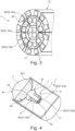
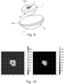
- FIGS 1 , 4 and 9 show three exemplary embodiments of a lamp 1 according to the present invention.
- These lights 1 are all characterized in that they have a light source 2, a pre-optics 3 downstream of the light source in the light guidance direction L and an outcoupling optics 4 downstream of the fore-optics in the light guidance direction L.
- the direction of light guidance corresponds to the main direction that the light takes through the lamp 1; This preferably corresponds to the main radiation direction H of the lamp 1.
- the light source 2 is divided into individually controllable light segments 20.
- the light source 2 can, for example, comprise an LED matrix which has a large number of individually controllable LEDs 21, which form the individually controllable light segments 20. Any number of LEDs can be provided in any LED matrix arrangement.
- the LEDs can be controlled individually or in groups. The groups of LEDs are preferably designed in the same way, i.e. preferably have the same LEDs.
- the light source 2 has an elongated light mixing rod 22 with a (third) light coupling side 220 and a (third) light coupling side 221 which is opposite the (third) light coupling side 220 with respect to its elongated extent.
- the light mixing rod 22 is divided into several segments 222, which form the individually controllable light segments 20.
- the segments 222 each extend longitudinally between the light input side 220 and the light output side 221 of the light mixing rod 22.
- the segments 222 can have a central rod element 222a and ring elements 222b and/or ring segments 222c surrounding the central rod element 222a on the circumference.
- Other arrangements of the segments 222 are also conceivable.
- the segments 222 of the light mixing rod 22 can have an at least partially angular cross section.
- at least the central rod element 222a can have a substantially hexagonal cross section.
- the simplest possible cross-sectional shape can be achieved while at the same time simply providing a compact structure of the light mixing rod 22, such as in particular Figures 2 and 3 can be seen. This is because the elements 222b or segments 222c surrounding the circumference can be arranged compactly around this hexagonal central rod element 222a.
- the light mixing rod 22 can merge or taper into a defined cross-sectional shape towards the pre-optics 3 or towards its third light output side 221.
- a round cross-sectional shape is conceivable here.
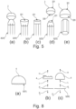
- the light mixing rod 22 preferably changes into a round cross-sectional shape, this happening by converging (cf. Figures 5a and 5d ), expand (cf. Figure 5b ) or a constant cross section (cf. Figure 5c ) is conceivable.
- one or a group of individually controllable LEDs 21 are assigned to the segments 222 on the light input side 220 of the light mixing rod 22. These LEDs 21 can be formed by the LED matrix described above. As previously described, in this exemplary embodiment a possible group of LEDs can be designed in the same way for all segments 222 or even just a part of them; These then have the same LEDs in order to achieve a harmonious light output.
- the light mixing rod 22 and consequently its segments 222 preferably have a length of at least 30mm, preferably at least 50mm, particularly preferably at least 80mm.
- the pre-optics 3 of the lamp 1 according to the invention has a first light coupling side 320 for coupling the light of each of the light segments 20 of the light source 2.
- the lamp 1 is provided in such a way that the light of this light segment 20 is selectively coupled into the pre-optics via each light segment 20, if it is controlled.
- the light output side 221 of the light mixing rod 22 preferably points to the first light input side 320 of the pre-optics 3 and is particularly preferably in (flat) contact with it or is integrally formed with it.
- the respective LEDs are preferably directed in the emission direction onto the light input side 320 of the pre-optics 3.
- the light source - preferably the LED matrix or the light mixing rod 20 and in particular its third light coupling side 221 - is preferably in contact with the first light coupling side 320 of the pre-optics 3.
- a flat contact is particularly preferred here, as is the case in the exemplary embodiments Figures 1 , 4 , 5 and 9 is shown.
- At least some of the segments 222 - here preferably at least the central rod element 222a - can be formed integrally with the pre-optics 3.
- the pre-optics 3 also has a first light output side 321 for defined light output.
- the pre-optics 3 can have a spherical lens such as a hemispherical lens or can be designed as such.
- the first light coupling side 320 can be at least partially flat; preferably at least the area of the light input side 320 that is opposite the light source 2 or is in contact with it.
- the first output side 321 can preferably be spherical and in particular hemispherical in shape in order to achieve a correspondingly desired pre-bundling of the light before it enters the output optics 4 downstream of the pre-optics 3 make possible.
- the pre-optics 3 is followed by the aforementioned decoupling optics 4; in particular in such a way that the light coupled out of the pre-optics 3 can be completely coupled into the decoupling optics 4.
- the coupling-out optics 4 has a second light-coupling side 420 for coupling in the light coupled out of the pre-optics 3 and a second light-coupling side 421 for the defined light output of the lamp 1, as exemplified in the Figure 1 is shown.
- the decoupling optics 4 is not limited to a specific shape. In particular, the shape depends on the desired radiation characteristics of the lamp 1.
- the decoupling optics 4 can be a spherical lens, an aspherical lens or even a Fresnel lens.
- the second light output side 421 of the output optics 4 is designed accordingly, for example in FIG Figures 1 , 4 , 8th and 9 shown.
- the coupling-out optics 4 has a flat second light-coupling side 420, via which the light coming from the pre-optics 3 can preferably be coupled in completely and in a targeted manner.
- the lamp 1 according to the invention can also have a scattering structure 5.
- This is preferably arranged between the pre-optics 3 and the decoupling optics 4 and serves to (further) soften the light output achieved by the lamp or to image a light distribution corresponding to the controlled light segments 20 in an illumination level B downstream of the decoupling optics 4.
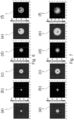
- Figures 6 and 7 refer to. While Figure 6 represents different control variants of the present invention (ring structures are increasingly switched on electrically from left to right, so that a kind of electrical zoom effect is achieved, in the two right ones representations of the Figure 6 a single light segment 20 is left out in order to achieve an asymmetrical light distribution).
- Figure 7 shows the same images as Figure 6 with additional use of a scattering structure 5 according to the invention.
- the scattering structure 5 By means of the scattering structure 5, the light decoupled from the pre-optics 3 is consequently scattered before the light scattered in this way is coupled into the decoupling optics 4, preferably via the second light input side 420.
- the scattering structure 5 can be arranged as a separate scattering disk 50 between the pre-optics 3 and the decoupling optics 4, as exemplified in FIGS Figures 8b and 9 is shown.
- the lens can be used, as in the Figure 9 shown, fixed to or directly on the output optics 4 and in particular the second light input side 420.
- the diffuser 50 is arranged to be movable P1, P2 in the light guide direction L or in the main emission direction H of the lamp 1 between the pre-optics 3 and the output optics 4 and in particular movable relative to the output optics 4.
- a manipulation unit (not shown here) for moving the lens 50 can be provided. This can be driven mechanically or electrically, for example.
- a diffusing disk 50 provided in such a movable manner is, for example Figure 8b refer to.
- the scattering structure 5 is provided directly in the coupling-out optics 4 and in particular on the second light coupling side 420 as a surface structure 51, as is the case in the embodiment according to Figure 4 is shown. Any combination of previously described and/or other known scattering structures 5 is also conceivable.
- the lamp 1 according to the invention can also have a lamp housing 6, in which the individual elements of the lamp 1, i.e. in particular the light source 2, the pre-optics 3 and the outcoupling optics 4 and optionally also the scattering structure 5, are arranged. Since the image of the light segments 20 on an illumination level B can be varied by selectively controlling the light segments 20 individually and, if necessary, even a zoom effect can be achieved, which is generated purely electrically, the individual elements of the lamp 1 according to the invention can preferably be in one be provided in a fixed relative arrangement to one another, which considerably simplifies the structure of the lamp 1 with variable adjustment options for the radiation characteristics; For example, compared to a light with a mechanically adjustable Zoom. Only in a preferred embodiment is it conceivable that individual elements - particularly preferably the scattering structure 5 - are additionally movable P1, P2.
- the individually controllable light segments 20 can then be selectively controlled to image a light distribution corresponding to the controlled light segments 20 in an illumination level B downstream of the output optics 4, in order to achieve corresponding different images.
- an optionally provided separate lens 50 preferably in the light guiding direction L between the pre-optics 3 and the output optics 4 and in particular relative to the output optics 4, the sharpness of the light image can, for example, additionally be adjusted.
- an appropriately provided manipulation unit is preferably used.
- the present invention it is therefore possible to easily achieve the image of a lamp 1 by means of electrical control of individually controllable light segments 20 - by means of a light distribution corresponding to the controlled light segments 20 - in an illumination level B downstream of the lamp 1 or its output optics 4.
- the image of the individual light segments can also be blurred in order to achieve a particularly harmonious light image overall.
- a particularly homogeneous light mixing can be made possible and thus an overall homogeneous light emission or light image can be achieved.
- the shape of the individual elements is not limited by the present invention, provided that the light source 2 can couple the light into individually controllable light segments 20 into a pre-optics 3 and can in turn couple this from this into an outcoupling optics 4 downstream of the pre-optics 3, in order to thus achieve a to achieve defined light output via the coupling optics 4.
- the light source 2 can couple the light into individually controllable light segments 20 into a pre-optics 3 and can in turn couple this from this into an outcoupling optics 4 downstream of the pre-optics 3, in order to thus achieve a to achieve defined light output via the coupling optics 4.
- Lamp 1 according to the invention can be achieved.
- the cross-sectional shape of the light mixing rod 22 and its individual segments 222 is also not limited by the invention.
- the number and color of the individual LEDs 21 as well as the arrangement of the LEDs 21 or design of the LED matrix are not limited by the invention.
- the relative arrangement of the individual elements (light source 2, pre-optics 3, output optics 4, scattering structure 5) to one another is not limited by the invention, provided that they preferably enable appropriate light guidance and imaging.
- a lamp 1 comprising: a light source 2, the light source 2 being divided into individually controllable light segments 20, a pre-optics 3 with a first light coupling side 320 for coupling the light of each of the light segments 20 of the light source 2 and a first light coupling side 321 for defined light decoupling, and a decoupling optics 4 downstream of the pre-optics 3 with a second light coupling side 420 for coupling in the light coupled out of the pre-optics 3 and a second light coupling side 421 for defined light emission.
- the light source 2 can comprise an LED matrix which has a large number of individually controllable LEDs 21, which form the individually controllable light segments 20.
- the light source 2 can have an elongated light mixing rod 22 with a third light coupling side 220 and a third light coupling side 221 opposite the third light coupling side 220 with respect to its elongated extent, the light mixing rod 22 being able to be divided into several segments 222, which form and are the individually controllable light segments 20 each extend between the third light input side 220 and the third light output side 221.
- the segments 222 can have a central rod element 222a and ring elements 222b and/or ring segments 222c surrounding the central rod element 222a on the circumference.
- At least some of the segments 222 preferably at least the central rod element 222a, can be formed integrally with the pre-optics 3.
- the segments 222 of the light mixing rod 22 can have an at least partially angular cross section, preferably at least the central rod element 222a can have a substantially hexagonal cross section.
- the light mixing rod 22 can merge into a defined cross-sectional shape, preferably a round cross-sectional shape, towards the pre-optics 3 or towards its third light decoupling side 321 and in particular taper.
- the segments 222 on the side of the third light input side 220 of the light mixing rod 22 can each be assigned one or a group of individually controllable LEDs 21, which are preferably provided in the form of the LED matrix, whereby the groups of LEDs 21 can preferably be designed in the same way.
- the light mixing rod 22 can have a length of at least 30mm, preferably at least 50mm, particularly preferably at least 80mm.
- the light source 2 preferably the LED matrix or the light mixing rod 22 and in particular its third light output side 221, can be in contact, preferably in flat contact, with the first light input side 320 of the pre-optics 3.
- the pre-optics 3 can have a spherical lens such as a hemispherical lens, wherein preferably the first light input side 320 can be at least partially flat and the first light output side 321 can be spherical, in particular hemispherical.
- the output optics 4 can be a spherical lens, an aspherical lens or a Fresnel lens.
- the coupling-out optics 4 can have a flat second light coupling side 420.
- the lamp 1 can also have a scattering structure 5, which is preferably arranged between the pre-optics 3 and the decoupling optics 4 in such a way as to scatter the light coupled out from the pre-optics 3 before the light scattered in this way preferably via the second light coupling side 420 into the decoupling optics 4 can be coupled in.
- a scattering structure 5 which is preferably arranged between the pre-optics 3 and the decoupling optics 4 in such a way as to scatter the light coupled out from the pre-optics 3 before the light scattered in this way preferably via the second light coupling side 420 into the decoupling optics 4 can be coupled in.
- the scattering structure 5 can be arranged as a separate scattering disk 50 between the pre-optics 3 and the decoupling optics 4.
- the diffusing disk 50 can be provided relatively fixed to or directly on the coupling-out optics 4, in particular the second light coupling-in side 420.
- the diffusing disk 50 can preferably be arranged to be movable in the light guiding direction L or in the main emission direction H of the lamp 1 between the pre-optics 3 and the decoupling optics 4, in particular movable relative to the decoupling optics 4, and preferably also have a manipulation unit for moving the diffusing disk 50.
- the scattering structure 5 can be provided directly in the coupling-out optics 4, in particular on the second light coupling-in side 420, as a surface structure 51.
- a method for controlling the emission characteristics of a lamp 1 comprising the steps: providing the previously described lamp 1, and selectively controlling the individually controllable light segments 20 to image a light distribution corresponding to the controlled light segments 20 in an illumination level B downstream of the output optics 4 .
- the method can further include the step of selectively moving the separate lens 50, preferably in the light guide direction L or in the main emission direction H between the pre-optics 3 and the output optics 4, in particular relative to the output optics 4, preferably by means of the manipulation unit, to adjust the sharpness of the image of the light distribution on the lighting level B.
Landscapes
- Physics & Mathematics (AREA)
- Engineering & Computer Science (AREA)
- Optics & Photonics (AREA)
- General Engineering & Computer Science (AREA)
- General Physics & Mathematics (AREA)
- Microelectronics & Electronic Packaging (AREA)
- Non-Portable Lighting Devices Or Systems Thereof (AREA)
Claims (13)
- Luminaire (1), présentant :une source de lumière (2), dans lequel la source de lumière (2) est divisée en segments lumineux (20) pouvant être commandés individuellement,une pré-optique (3) comportant un premier côté d'injection de lumière (320) pour l'injection de la lumière de chacun des segments lumineux (20) de la source de lumière (2), ainsi qu'un premier côté de sortie de lumière (321) pour la sortie définie de lumière, etune optique de sortie (4) en aval de la pré-optique (3) et comportant un deuxième côté d'injection de lumière (420) pour l'injection de la lumière éjectée de la pré-optique (3), ainsi qu'un deuxième côté de sortie de lumière (421) pour l'émission définie de lumière,caractérisé en ce quele luminaire (1) est conçu de telle sorte qu'une répartition de lumière correspondant aux segments lumineux (20) commandés est projetée dans un plan d'éclairage (B) en aval de l'optique de sortie (4), en ce que la source de lumière (2) présente une barre mélangeuse de lumière (22) allongée comportant un troisième côté d'injection de lumière (220) et un troisième côté de sortie de lumière (221) opposé au troisième côté d'injection de lumière (220) relativement à son extension allongée, dans lequel la barre mélangeuse de lumière (22) est divisée en plusieurs segments (222) qui forment les segments lumineux (20) commandés individuellement et s'étendent respectivement entre le troisième côté d'injection de lumière (320) et le troisième côté de sortie de lumière (321), eten ce que les segments (222) présentent un élément de barre (222a) central, et l'élément de barre (222a) central présente, sur sa périphérie, des éléments annulaires (222b) et/ou des segments annulaires (222c) environnants.
- Luminaire (1) selon la revendication 1, dans lequel la source de lumière (2) comprend une matrice LED qui présente une pluralité de LED (21) pouvant être commandées individuellement, lesquelles LED forment les segments lumineux (20) pouvant être commandés individuellement.
- Luminaire (1) selon la revendication 1 ou 2, dans lequel au moins une partie des segments (222), de préférence au moins l'élément de barre (222a) central, est conçue d'un seul tenant avec la pré-optique (3).
- Luminaire (1) selon l'une des revendications 1 à 3, dans lequel les segments (222) de la barre mélangeuse de lumière (22) présentent une section au moins partiellement angulaire, dans lequel de préférence au moins l'élément de barre (222a) central présente sensiblement une section hexagonale.
- Luminaire (1) selon l'une des revendications 1 à 4,dans lequel la barre mélangeuse de lumière (22) se transforme en, et en particulier converge vers, une forme de section transversale définie, de préférence une forme de section transversale ronde, en direction de la pré-optique (3) ou de son troisième côté de sortie de lumière (321), et/oudans lequel la barre mélangeuse de lumière (22) présente une longueur d'au moins 30 mm, de préférence d'au moins 50 mm, plus préférablement d'au moins 80 mm.
- Luminaire (1) selon l'une des revendications 1 à 5, dans lequel respectivement une LED ou un groupe de LED (21) pouvant être commandées individuellement est associé(e) aux segments (222) sur des côtés du troisième côté d'injection de lumière (220) de la barre mélangeuse de lumière (22), lesquelles LED sont de préférence fournies sous la forme de la matrice LED, dans lequel les groupes de LED (21) sont de préférence conçus de façon identique.
- Luminaire (1) selon l'une des revendications précédentes, dans lequel la source de lumière (2), de préférence la matrice LED ou la barre mélangeuse de lumière (22) et en particulier son troisième côté de sortie de lumière (221) est en contact, de préférence en contact plat, avec le troisième côté d'injection de lumière (320) de la pré-optique (3).
- Luminaire (1) selon l'une des revendications précédentes, dans lequel la pré-optique (3) présente une lentille sphérique comme une lentille hémisphérique, dans lequel de préférence le premier côté d'injection de lumière (320) est conçu au moins partiellement plat et le premier côté de sortie de lumière (321) est sphérique, en particulier hémisphérique.
- Luminaire (1) selon l'une des revendications précédentes, dans lequel l'optique de sortie (4) est une lentille sphérique, une lentille asphérique ou une lentille de Fresnel.
- Luminaire (1) selon l'une des revendications précédentes, dans lequel l'optique de sortie (4) présente un deuxième côté d'injection (420) plat.
- Luminaire (1) selon l'une des revendications précédentes, présentant en outre une structure de diffusion (5) qui est de préférence disposée entre la pré-optique (3) et l'optique de sortie (4) de façon à diffuser la lumière éjectée par la pré-optique (3) avant que la lumière ainsi diffusée ne soit injectée dans l'optique de sortie (4) par l'intermédiaire du deuxième côté d'injection de lumière (420),dans lequel de préférence la structure de diffusion (5) est de disposé comme diffuseur (50) séparé entre la pré-optique (3) et l'optique de sortie (4),dans lequel en outre de préférence le diffuseur (50) est prévu relativement fixe par rapport à l'optique de sortie (4) ou directement sur celui-ci, en particulier relativement fixe par rapport au deuxième côté d'injection de lumière (420) ou sur celui-ci, et/oudans lequel en outre de préférence le diffuseur (50) est disposé de préférence dans la direction de guidage de lumière (L) ou dans la direction de rayonnement principale (H) du luminaire (1), entre la pré-optique (3) et l'optique de sortie (4), en particulier mobile par rapport à l'optique de sortie (4), dans lequel le luminaire (1) présente plus préférablement une unité de manipulation pour le déplacement du diffuseur (50), et/oudans lequel de préférence la structure de diffusion (5) est fournie, structure de surface (51), directement dans l'optique de sortie (4), en particulier sur le deuxième côté d'injection de lumière (420).
- Procédé pour le commande d'une caractéristique de rayonnement d'un luminaire (1), présentant les étapes de :• fourniture d'un luminaire (1) selon l'une des revendications précédentes,• commande sélective des segments lumineux (20) pouvant être commandés individuellement pour la représentation, dans un plan d'éclairage (B) en aval de l'optique de sortie (4), d'une répartition de lumière correspondant aux segments lumineux (20) commandés.
- Procédé selon la revendication 12, présentant en outre l'étape de déplacement sélectif du diffuseur (50) séparé du luminaire (1) selon la revendication 11, de préférence dans la direction de guidage de lumière (L) ou dans la direction de rayonnement principale (H) entre la pré-optique (3) et l'optique de sortie (4), en particulier par rapport à l'optique de sortie (4), de préférence à l'aide de l'unité de manipulation, pour le réglage de la netteté de la représentation de la répartition de lumière sur le plan d'éclairage (B).
Priority Applications (2)
| Application Number | Priority Date | Filing Date | Title |
|---|---|---|---|
| EP19203191.2A EP3623695B1 (fr) | 2017-02-14 | 2018-02-13 | Luminaire ainsi que procédé de commande des caractéristiques du rayonnement dudit luminaire, conduit de mélangeur de lumière et luminaire pourvu de conduit de mélangeur de lumière |
| EP19203183.9A EP3623694B1 (fr) | 2017-02-14 | 2018-02-13 | Luminaire ainsi que procédé de commande des caractéristiques du rayonnement dudit luminaire, conduit de mélangeur de lumière et luminaire pourvu de conduit de mélangeur de lumière |
Applications Claiming Priority (7)
| Application Number | Priority Date | Filing Date | Title |
|---|---|---|---|
| DE102017202277 | 2017-02-14 | ||
| DE102017213466.6A DE102017213466A1 (de) | 2017-08-03 | 2017-08-03 | Lichtmischleiter |
| DE102017213488.7A DE102017213488A1 (de) | 2017-02-14 | 2017-08-03 | Leuchte sowie Verfahren zur Steuerung der Abstrahlcharakteristik derselben |
| DE102017213462.3A DE102017213462A1 (de) | 2017-08-03 | 2017-08-03 | Lichtmischleiter |
| DE102017214395.9A DE102017214395A1 (de) | 2017-02-14 | 2017-08-18 | Leuchte sowie Verfahren zur Steuerung der Abstrahlcharakteristik derselben |
| DE202017107771.3U DE202017107771U1 (de) | 2017-02-14 | 2017-12-20 | Lichtmischleiter und Leuchte mit Lichtmischleiter |
| PCT/EP2018/053478 WO2018149796A2 (fr) | 2017-02-14 | 2018-02-13 | Lampe et procédé pour en commander la caractéristique de rayonnement, guide de lumière mixte et lampe équipée d'un guide de lumière mixte |
Related Child Applications (4)
| Application Number | Title | Priority Date | Filing Date |
|---|---|---|---|
| EP19203183.9A Division-Into EP3623694B1 (fr) | 2017-02-14 | 2018-02-13 | Luminaire ainsi que procédé de commande des caractéristiques du rayonnement dudit luminaire, conduit de mélangeur de lumière et luminaire pourvu de conduit de mélangeur de lumière |
| EP19203183.9A Division EP3623694B1 (fr) | 2017-02-14 | 2018-02-13 | Luminaire ainsi que procédé de commande des caractéristiques du rayonnement dudit luminaire, conduit de mélangeur de lumière et luminaire pourvu de conduit de mélangeur de lumière |
| EP19203191.2A Division-Into EP3623695B1 (fr) | 2017-02-14 | 2018-02-13 | Luminaire ainsi que procédé de commande des caractéristiques du rayonnement dudit luminaire, conduit de mélangeur de lumière et luminaire pourvu de conduit de mélangeur de lumière |
| EP19203191.2A Division EP3623695B1 (fr) | 2017-02-14 | 2018-02-13 | Luminaire ainsi que procédé de commande des caractéristiques du rayonnement dudit luminaire, conduit de mélangeur de lumière et luminaire pourvu de conduit de mélangeur de lumière |
Publications (2)
| Publication Number | Publication Date |
|---|---|
| EP3583352A2 EP3583352A2 (fr) | 2019-12-25 |
| EP3583352B1 true EP3583352B1 (fr) | 2023-12-27 |
Family
ID=63169165
Family Applications (2)
| Application Number | Title | Priority Date | Filing Date |
|---|---|---|---|
| EP18706682.4A Active EP3583352B1 (fr) | 2017-02-14 | 2018-02-13 | Lampe et procédé pour en commander la caractéristique de rayonnement |
| EP19203191.2A Active EP3623695B1 (fr) | 2017-02-14 | 2018-02-13 | Luminaire ainsi que procédé de commande des caractéristiques du rayonnement dudit luminaire, conduit de mélangeur de lumière et luminaire pourvu de conduit de mélangeur de lumière |
Family Applications After (1)
| Application Number | Title | Priority Date | Filing Date |
|---|---|---|---|
| EP19203191.2A Active EP3623695B1 (fr) | 2017-02-14 | 2018-02-13 | Luminaire ainsi que procédé de commande des caractéristiques du rayonnement dudit luminaire, conduit de mélangeur de lumière et luminaire pourvu de conduit de mélangeur de lumière |
Country Status (2)
| Country | Link |
|---|---|
| EP (2) | EP3583352B1 (fr) |
| WO (1) | WO2018149796A2 (fr) |
Families Citing this family (4)
| Publication number | Priority date | Publication date | Assignee | Title |
|---|---|---|---|---|
| DE102020134279A1 (de) | 2020-12-18 | 2022-06-23 | Bartenbach Holding Gmbh | Zoom-Strahler |
| DE102022115898A1 (de) * | 2022-06-27 | 2023-12-28 | Zumtobel Lighting Gmbh | Optisches Element |
| EP4710038A1 (fr) | 2023-05-08 | 2026-03-18 | Signify Holding B.V. | Agencement d'éclairage comprenant un élément optique de collimation de lumière et réseau de diodes électroluminescentes |
| IT202300010926A1 (it) * | 2023-05-30 | 2024-11-30 | Clay Paky S R L | Proiettore con uniformita' di colori migliorata e metodo per operare detto proiettore |
Citations (2)
| Publication number | Priority date | Publication date | Assignee | Title |
|---|---|---|---|---|
| EP0535401A1 (fr) * | 1991-09-30 | 1993-04-07 | Motorola, Inc. | Affichage compact d'image virtuel |
| US20160154193A1 (en) * | 2014-12-02 | 2016-06-02 | Innovations In Optics, Inc. | High radiance light emitting diode light engine |
Family Cites Families (9)
| Publication number | Priority date | Publication date | Assignee | Title |
|---|---|---|---|---|
| EP1789824A4 (fr) * | 2004-08-23 | 2009-01-21 | Optical Res Associates | Systemes d'eclairage conçus pour produire differentes formes de faisceaux |
| EP1672755B1 (fr) * | 2004-12-17 | 2015-09-23 | Nichia Corporation | Dispositif émetteur de lumière |
| US7777955B2 (en) * | 2005-07-29 | 2010-08-17 | Optical Research Associates | Rippled mixers for uniformity and color mixing |
| US20100097802A1 (en) * | 2008-10-20 | 2010-04-22 | Robe Lighting S.R.O. | Light collection system for an led luminaire |
| EP2591282A1 (fr) * | 2010-07-09 | 2013-05-15 | Koninklijke Philips Electronics N.V. | Ensemble zoom optique pour application d'éclairage sans image et luminaire l'utilisant |
| US9052417B2 (en) * | 2011-04-08 | 2015-06-09 | Brite Shot, Inc. | LED array lighting assembly |
| US8469571B2 (en) * | 2011-09-06 | 2013-06-25 | Asia Optical International Ltd. | Light guide and housing assembly |
| AT513917B1 (de) * | 2013-02-05 | 2014-11-15 | Zizala Lichtsysteme Gmbh | Leuchteinheit für einen Scheinwerfer sowie Scheinwerfer |
| WO2014209702A1 (fr) * | 2013-06-28 | 2014-12-31 | Innovations In Optics, Inc. | Éclairage linéaire par diodes électroluminescentes à champ lointain uniforme |
-
2018
- 2018-02-13 WO PCT/EP2018/053478 patent/WO2018149796A2/fr not_active Ceased
- 2018-02-13 EP EP18706682.4A patent/EP3583352B1/fr active Active
- 2018-02-13 EP EP19203191.2A patent/EP3623695B1/fr active Active
Patent Citations (2)
| Publication number | Priority date | Publication date | Assignee | Title |
|---|---|---|---|---|
| EP0535401A1 (fr) * | 1991-09-30 | 1993-04-07 | Motorola, Inc. | Affichage compact d'image virtuel |
| US20160154193A1 (en) * | 2014-12-02 | 2016-06-02 | Innovations In Optics, Inc. | High radiance light emitting diode light engine |
Also Published As
| Publication number | Publication date |
|---|---|
| EP3583352A2 (fr) | 2019-12-25 |
| WO2018149796A3 (fr) | 2018-11-08 |
| WO2018149796A2 (fr) | 2018-08-23 |
| EP3623695A1 (fr) | 2020-03-18 |
| EP3623695B1 (fr) | 2021-12-01 |
Similar Documents
| Publication | Publication Date | Title |
|---|---|---|
| EP3583352B1 (fr) | Lampe et procédé pour en commander la caractéristique de rayonnement | |
| EP2893249B1 (fr) | Unité d'éclairage destinée à un projecteur | |
| AT517523B1 (de) | Leuchteinrichtung für einen KFZ-Scheinwerfer | |
| DE10325330B4 (de) | Scheinwerfer für Kraftfahrzeuge | |
| EP2028510A2 (fr) | Dispositif d'éclairage, en particulier pour véhicules | |
| AT520399A1 (de) | Beleuchtungsvorrichtung und/oder signalisierungsvorrichtung für ein kraftfahrzeug | |
| DE102008036616A1 (de) | Flächenprojektionssystem zur Abbildung eines visuellen Signals auf einer Oberfläche | |
| EP1150154A1 (fr) | Procédé et méthode d'illumination annulaire, en particulier système d'illumination incident pour microscopes | |
| DE3208753A1 (de) | Epidunkles beleuchtungssystem | |
| WO2019158348A1 (fr) | Phare de véhicule automobile à éléments guides de lumière agencé sous forme de matrice | |
| EP3765780B1 (fr) | Dispositif d'eclairage pour un phare de vehicule automobile | |
| DE102014207419A1 (de) | Kraftfahrzeug mit wenigstens einer Projektionsvorrichtung zur Erzeugung wenigstens einer räumlich abgegrenzten Lichtprojektion | |
| DE102006037797B4 (de) | Kraftfahrzeugleuchte | |
| DE10016882A1 (de) | Beleuchtungseinrichtung und Verfahren zum Betreiben einer Beleuchtungseinrichtung | |
| AT519125A4 (de) | Leuchtvorrichtung für einen Kraftfahrzeugscheinwerfer sowie Kraftfahrzeugscheinwerfer | |
| DE10030772A1 (de) | Anordnung und Verfahren zur Beleuchtung, insbesondere Auflichtbeleuchtung bei Mikroskopen mit einem um die optische Achse orientierten Ringträger zur Aufnahme von Beleuchtungsmitteln | |
| DE102017214395A1 (de) | Leuchte sowie Verfahren zur Steuerung der Abstrahlcharakteristik derselben | |
| DE102019125571A1 (de) | Beleuchtungsvorrichtung für ein Kraftfahrzeug | |
| DE102013221953A1 (de) | Leuchtvorrichtung für ein Kraftfahrzeug | |
| DE102013106620A1 (de) | Beleuchtungsvorrichtung für Fahrzeuge | |
| DE102013016346A1 (de) | Fahrzeuginnenraum-Bauteil zur Erzeugung einer Ambientebeleuchtung | |
| AT516296B1 (de) | Ausfallsichere Symboldarstellungen mit LED-Lichtquelle und Lichtleiter | |
| AT17575U1 (de) | Leuchte sowie Verfahren zur Steuerung der Abstrahlcharakteristik derselben | |
| DE20213911U1 (de) | Scheinwerfer, insbesondere für Kraftfahrzeuge | |
| DE102005006674B4 (de) | Scheinwerfereinrichtung für Kraftfahrzeuge |
Legal Events
| Date | Code | Title | Description |
|---|---|---|---|
| STAA | Information on the status of an ep patent application or granted ep patent |
Free format text: STATUS: UNKNOWN |
|
| STAA | Information on the status of an ep patent application or granted ep patent |
Free format text: STATUS: THE INTERNATIONAL PUBLICATION HAS BEEN MADE |
|
| PUAI | Public reference made under article 153(3) epc to a published international application that has entered the european phase |
Free format text: ORIGINAL CODE: 0009012 |
|
| STAA | Information on the status of an ep patent application or granted ep patent |
Free format text: STATUS: REQUEST FOR EXAMINATION WAS MADE |
|
| 17P | Request for examination filed |
Effective date: 20190911 |
|
| AK | Designated contracting states |
Kind code of ref document: A2 Designated state(s): AL AT BE BG CH CY CZ DE DK EE ES FI FR GB GR HR HU IE IS IT LI LT LU LV MC MK MT NL NO PL PT RO RS SE SI SK SM TR |
|
| AX | Request for extension of the european patent |
Extension state: BA ME |
|
| DAV | Request for validation of the european patent (deleted) | ||
| DAX | Request for extension of the european patent (deleted) | ||
| STAA | Information on the status of an ep patent application or granted ep patent |
Free format text: STATUS: EXAMINATION IS IN PROGRESS |
|
| 17Q | First examination report despatched |
Effective date: 20210616 |
|
| GRAP | Despatch of communication of intention to grant a patent |
Free format text: ORIGINAL CODE: EPIDOSNIGR1 |
|
| STAA | Information on the status of an ep patent application or granted ep patent |
Free format text: STATUS: GRANT OF PATENT IS INTENDED |
|
| INTG | Intention to grant announced |
Effective date: 20230922 |
|
| GRAS | Grant fee paid |
Free format text: ORIGINAL CODE: EPIDOSNIGR3 |
|
| GRAA | (expected) grant |
Free format text: ORIGINAL CODE: 0009210 |
|
| STAA | Information on the status of an ep patent application or granted ep patent |
Free format text: STATUS: THE PATENT HAS BEEN GRANTED |
|
| AK | Designated contracting states |
Kind code of ref document: B1 Designated state(s): AL AT BE BG CH CY CZ DE DK EE ES FI FR GB GR HR HU IE IS IT LI LT LU LV MC MK MT NL NO PL PT RO RS SE SI SK SM TR |
|
| REG | Reference to a national code |
Ref country code: GB Ref legal event code: FG4D Free format text: NOT ENGLISH |
|
| REG | Reference to a national code |
Ref country code: CH Ref legal event code: EP |
|
| REG | Reference to a national code |
Ref country code: DE Ref legal event code: R096 Ref document number: 502018013860 Country of ref document: DE |
|
| P01 | Opt-out of the competence of the unified patent court (upc) registered |
Effective date: 20231130 |
|
| REG | Reference to a national code |
Ref country code: IE Ref legal event code: FG4D Free format text: LANGUAGE OF EP DOCUMENT: GERMAN |
|
| REG | Reference to a national code |
Ref country code: DE Ref legal event code: R084 Ref document number: 502018013860 Country of ref document: DE |
|
| PG25 | Lapsed in a contracting state [announced via postgrant information from national office to epo] |
Ref country code: GR Free format text: LAPSE BECAUSE OF FAILURE TO SUBMIT A TRANSLATION OF THE DESCRIPTION OR TO PAY THE FEE WITHIN THE PRESCRIBED TIME-LIMIT Effective date: 20240328 |
|
| REG | Reference to a national code |
Ref country code: LT Ref legal event code: MG9D |
|
| PG25 | Lapsed in a contracting state [announced via postgrant information from national office to epo] |
Ref country code: LT Free format text: LAPSE BECAUSE OF FAILURE TO SUBMIT A TRANSLATION OF THE DESCRIPTION OR TO PAY THE FEE WITHIN THE PRESCRIBED TIME-LIMIT Effective date: 20231227 |
|
| PG25 | Lapsed in a contracting state [announced via postgrant information from national office to epo] |
Ref country code: ES Free format text: LAPSE BECAUSE OF FAILURE TO SUBMIT A TRANSLATION OF THE DESCRIPTION OR TO PAY THE FEE WITHIN THE PRESCRIBED TIME-LIMIT Effective date: 20231227 |
|
| PG25 | Lapsed in a contracting state [announced via postgrant information from national office to epo] |
Ref country code: LT Free format text: LAPSE BECAUSE OF FAILURE TO SUBMIT A TRANSLATION OF THE DESCRIPTION OR TO PAY THE FEE WITHIN THE PRESCRIBED TIME-LIMIT Effective date: 20231227 Ref country code: GR Free format text: LAPSE BECAUSE OF FAILURE TO SUBMIT A TRANSLATION OF THE DESCRIPTION OR TO PAY THE FEE WITHIN THE PRESCRIBED TIME-LIMIT Effective date: 20240328 Ref country code: FI Free format text: LAPSE BECAUSE OF FAILURE TO SUBMIT A TRANSLATION OF THE DESCRIPTION OR TO PAY THE FEE WITHIN THE PRESCRIBED TIME-LIMIT Effective date: 20231227 Ref country code: ES Free format text: LAPSE BECAUSE OF FAILURE TO SUBMIT A TRANSLATION OF THE DESCRIPTION OR TO PAY THE FEE WITHIN THE PRESCRIBED TIME-LIMIT Effective date: 20231227 Ref country code: BG Free format text: LAPSE BECAUSE OF FAILURE TO SUBMIT A TRANSLATION OF THE DESCRIPTION OR TO PAY THE FEE WITHIN THE PRESCRIBED TIME-LIMIT Effective date: 20240327 |
|
| PGFP | Annual fee paid to national office [announced via postgrant information from national office to epo] |
Ref country code: DE Payment date: 20240228 Year of fee payment: 7 Ref country code: GB Payment date: 20240220 Year of fee payment: 7 |
|
| REG | Reference to a national code |
Ref country code: NL Ref legal event code: MP Effective date: 20231227 |
|
| PG25 | Lapsed in a contracting state [announced via postgrant information from national office to epo] |
Ref country code: NL Free format text: LAPSE BECAUSE OF FAILURE TO SUBMIT A TRANSLATION OF THE DESCRIPTION OR TO PAY THE FEE WITHIN THE PRESCRIBED TIME-LIMIT Effective date: 20231227 |
|
| PG25 | Lapsed in a contracting state [announced via postgrant information from national office to epo] |
Ref country code: SE Free format text: LAPSE BECAUSE OF FAILURE TO SUBMIT A TRANSLATION OF THE DESCRIPTION OR TO PAY THE FEE WITHIN THE PRESCRIBED TIME-LIMIT Effective date: 20231227 Ref country code: RS Free format text: LAPSE BECAUSE OF FAILURE TO SUBMIT A TRANSLATION OF THE DESCRIPTION OR TO PAY THE FEE WITHIN THE PRESCRIBED TIME-LIMIT Effective date: 20231227 Ref country code: NO Free format text: LAPSE BECAUSE OF FAILURE TO SUBMIT A TRANSLATION OF THE DESCRIPTION OR TO PAY THE FEE WITHIN THE PRESCRIBED TIME-LIMIT Effective date: 20240327 Ref country code: NL Free format text: LAPSE BECAUSE OF FAILURE TO SUBMIT A TRANSLATION OF THE DESCRIPTION OR TO PAY THE FEE WITHIN THE PRESCRIBED TIME-LIMIT Effective date: 20231227 Ref country code: LV Free format text: LAPSE BECAUSE OF FAILURE TO SUBMIT A TRANSLATION OF THE DESCRIPTION OR TO PAY THE FEE WITHIN THE PRESCRIBED TIME-LIMIT Effective date: 20231227 Ref country code: HR Free format text: LAPSE BECAUSE OF FAILURE TO SUBMIT A TRANSLATION OF THE DESCRIPTION OR TO PAY THE FEE WITHIN THE PRESCRIBED TIME-LIMIT Effective date: 20231227 |
|
| PGFP | Annual fee paid to national office [announced via postgrant information from national office to epo] |
Ref country code: FR Payment date: 20240226 Year of fee payment: 7 |
|
| PG25 | Lapsed in a contracting state [announced via postgrant information from national office to epo] |
Ref country code: IS Free format text: LAPSE BECAUSE OF FAILURE TO SUBMIT A TRANSLATION OF THE DESCRIPTION OR TO PAY THE FEE WITHIN THE PRESCRIBED TIME-LIMIT Effective date: 20240427 |
|
| PG25 | Lapsed in a contracting state [announced via postgrant information from national office to epo] |
Ref country code: CZ Free format text: LAPSE BECAUSE OF FAILURE TO SUBMIT A TRANSLATION OF THE DESCRIPTION OR TO PAY THE FEE WITHIN THE PRESCRIBED TIME-LIMIT Effective date: 20231227 |
|
| PG25 | Lapsed in a contracting state [announced via postgrant information from national office to epo] |
Ref country code: SK Free format text: LAPSE BECAUSE OF FAILURE TO SUBMIT A TRANSLATION OF THE DESCRIPTION OR TO PAY THE FEE WITHIN THE PRESCRIBED TIME-LIMIT Effective date: 20231227 |
|
| PG25 | Lapsed in a contracting state [announced via postgrant information from national office to epo] |
Ref country code: SM Free format text: LAPSE BECAUSE OF FAILURE TO SUBMIT A TRANSLATION OF THE DESCRIPTION OR TO PAY THE FEE WITHIN THE PRESCRIBED TIME-LIMIT Effective date: 20231227 Ref country code: SK Free format text: LAPSE BECAUSE OF FAILURE TO SUBMIT A TRANSLATION OF THE DESCRIPTION OR TO PAY THE FEE WITHIN THE PRESCRIBED TIME-LIMIT Effective date: 20231227 Ref country code: RO Free format text: LAPSE BECAUSE OF FAILURE TO SUBMIT A TRANSLATION OF THE DESCRIPTION OR TO PAY THE FEE WITHIN THE PRESCRIBED TIME-LIMIT Effective date: 20231227 Ref country code: IT Free format text: LAPSE BECAUSE OF FAILURE TO SUBMIT A TRANSLATION OF THE DESCRIPTION OR TO PAY THE FEE WITHIN THE PRESCRIBED TIME-LIMIT Effective date: 20231227 Ref country code: IS Free format text: LAPSE BECAUSE OF FAILURE TO SUBMIT A TRANSLATION OF THE DESCRIPTION OR TO PAY THE FEE WITHIN THE PRESCRIBED TIME-LIMIT Effective date: 20240427 Ref country code: EE Free format text: LAPSE BECAUSE OF FAILURE TO SUBMIT A TRANSLATION OF THE DESCRIPTION OR TO PAY THE FEE WITHIN THE PRESCRIBED TIME-LIMIT Effective date: 20231227 Ref country code: CZ Free format text: LAPSE BECAUSE OF FAILURE TO SUBMIT A TRANSLATION OF THE DESCRIPTION OR TO PAY THE FEE WITHIN THE PRESCRIBED TIME-LIMIT Effective date: 20231227 |
|
| PG25 | Lapsed in a contracting state [announced via postgrant information from national office to epo] |
Ref country code: PL Free format text: LAPSE BECAUSE OF FAILURE TO SUBMIT A TRANSLATION OF THE DESCRIPTION OR TO PAY THE FEE WITHIN THE PRESCRIBED TIME-LIMIT Effective date: 20231227 Ref country code: PT Free format text: LAPSE BECAUSE OF FAILURE TO SUBMIT A TRANSLATION OF THE DESCRIPTION OR TO PAY THE FEE WITHIN THE PRESCRIBED TIME-LIMIT Effective date: 20240429 |
|
| PG25 | Lapsed in a contracting state [announced via postgrant information from national office to epo] |
Ref country code: PT Free format text: LAPSE BECAUSE OF FAILURE TO SUBMIT A TRANSLATION OF THE DESCRIPTION OR TO PAY THE FEE WITHIN THE PRESCRIBED TIME-LIMIT Effective date: 20240429 Ref country code: PL Free format text: LAPSE BECAUSE OF FAILURE TO SUBMIT A TRANSLATION OF THE DESCRIPTION OR TO PAY THE FEE WITHIN THE PRESCRIBED TIME-LIMIT Effective date: 20231227 |
|
| PG25 | Lapsed in a contracting state [announced via postgrant information from national office to epo] |
Ref country code: MC Free format text: LAPSE BECAUSE OF FAILURE TO SUBMIT A TRANSLATION OF THE DESCRIPTION OR TO PAY THE FEE WITHIN THE PRESCRIBED TIME-LIMIT Effective date: 20231227 |
|
| REG | Reference to a national code |
Ref country code: DE Ref legal event code: R097 Ref document number: 502018013860 Country of ref document: DE Ref country code: CH Ref legal event code: PL |
|
| PG25 | Lapsed in a contracting state [announced via postgrant information from national office to epo] |
Ref country code: DK Free format text: LAPSE BECAUSE OF FAILURE TO SUBMIT A TRANSLATION OF THE DESCRIPTION OR TO PAY THE FEE WITHIN THE PRESCRIBED TIME-LIMIT Effective date: 20231227 |
|
| PG25 | Lapsed in a contracting state [announced via postgrant information from national office to epo] |
Ref country code: LU Free format text: LAPSE BECAUSE OF NON-PAYMENT OF DUE FEES Effective date: 20240213 |
|
| PG25 | Lapsed in a contracting state [announced via postgrant information from national office to epo] |
Ref country code: CH Free format text: LAPSE BECAUSE OF NON-PAYMENT OF DUE FEES Effective date: 20240229 |
|
| PG25 | Lapsed in a contracting state [announced via postgrant information from national office to epo] |
Ref country code: LU Free format text: LAPSE BECAUSE OF NON-PAYMENT OF DUE FEES Effective date: 20240213 Ref country code: DK Free format text: LAPSE BECAUSE OF FAILURE TO SUBMIT A TRANSLATION OF THE DESCRIPTION OR TO PAY THE FEE WITHIN THE PRESCRIBED TIME-LIMIT Effective date: 20231227 Ref country code: CH Free format text: LAPSE BECAUSE OF NON-PAYMENT OF DUE FEES Effective date: 20240229 |
|
| PLBE | No opposition filed within time limit |
Free format text: ORIGINAL CODE: 0009261 |
|
| STAA | Information on the status of an ep patent application or granted ep patent |
Free format text: STATUS: NO OPPOSITION FILED WITHIN TIME LIMIT |
|
| 26N | No opposition filed |
Effective date: 20240930 |
|
| REG | Reference to a national code |
Ref country code: BE Ref legal event code: MM Effective date: 20240229 |
|
| PG25 | Lapsed in a contracting state [announced via postgrant information from national office to epo] |
Ref country code: BE Free format text: LAPSE BECAUSE OF NON-PAYMENT OF DUE FEES Effective date: 20240229 |
|
| PG25 | Lapsed in a contracting state [announced via postgrant information from national office to epo] |
Ref country code: IE Free format text: LAPSE BECAUSE OF NON-PAYMENT OF DUE FEES Effective date: 20240213 |
|
| PG25 | Lapsed in a contracting state [announced via postgrant information from national office to epo] |
Ref country code: IE Free format text: LAPSE BECAUSE OF NON-PAYMENT OF DUE FEES Effective date: 20240213 Ref country code: BE Free format text: LAPSE BECAUSE OF NON-PAYMENT OF DUE FEES Effective date: 20240229 |
|
| REG | Reference to a national code |
Ref country code: AT Ref legal event code: MM01 Ref document number: 1644833 Country of ref document: AT Kind code of ref document: T Effective date: 20240213 |
|
| PG25 | Lapsed in a contracting state [announced via postgrant information from national office to epo] |
Ref country code: SI Free format text: LAPSE BECAUSE OF FAILURE TO SUBMIT A TRANSLATION OF THE DESCRIPTION OR TO PAY THE FEE WITHIN THE PRESCRIBED TIME-LIMIT Effective date: 20231227 Ref country code: AT Free format text: LAPSE BECAUSE OF NON-PAYMENT OF DUE FEES Effective date: 20240213 |
|
| PG25 | Lapsed in a contracting state [announced via postgrant information from national office to epo] |
Ref country code: CY Free format text: LAPSE BECAUSE OF FAILURE TO SUBMIT A TRANSLATION OF THE DESCRIPTION OR TO PAY THE FEE WITHIN THE PRESCRIBED TIME-LIMIT; INVALID AB INITIO Effective date: 20180213 |
|
| REG | Reference to a national code |
Ref country code: DE Ref legal event code: R119 Ref document number: 502018013860 Country of ref document: DE |
|
| PG25 | Lapsed in a contracting state [announced via postgrant information from national office to epo] |
Ref country code: HU Free format text: LAPSE BECAUSE OF FAILURE TO SUBMIT A TRANSLATION OF THE DESCRIPTION OR TO PAY THE FEE WITHIN THE PRESCRIBED TIME-LIMIT; INVALID AB INITIO Effective date: 20180213 |
|
| GBPC | Gb: european patent ceased through non-payment of renewal fee |
Effective date: 20250213 |
|
| PG25 | Lapsed in a contracting state [announced via postgrant information from national office to epo] |
Ref country code: TR Free format text: LAPSE BECAUSE OF FAILURE TO SUBMIT A TRANSLATION OF THE DESCRIPTION OR TO PAY THE FEE WITHIN THE PRESCRIBED TIME-LIMIT Effective date: 20231227 |
|
| PG25 | Lapsed in a contracting state [announced via postgrant information from national office to epo] |
Ref country code: DE Free format text: LAPSE BECAUSE OF NON-PAYMENT OF DUE FEES Effective date: 20250902 |
|
| PG25 | Lapsed in a contracting state [announced via postgrant information from national office to epo] |
Ref country code: GB Free format text: LAPSE BECAUSE OF NON-PAYMENT OF DUE FEES Effective date: 20250213 |
|
| PG25 | Lapsed in a contracting state [announced via postgrant information from national office to epo] |
Ref country code: FR Free format text: LAPSE BECAUSE OF NON-PAYMENT OF DUE FEES Effective date: 20250228 |