EP3583584B1 - Procédé de fonctionnement d'un dispositif de détection sur la base d'un protocole dsi et dispositif de détection correspondant - Google Patents
Procédé de fonctionnement d'un dispositif de détection sur la base d'un protocole dsi et dispositif de détection correspondant Download PDFInfo
- Publication number
- EP3583584B1 EP3583584B1 EP18705894.6A EP18705894A EP3583584B1 EP 3583584 B1 EP3583584 B1 EP 3583584B1 EP 18705894 A EP18705894 A EP 18705894A EP 3583584 B1 EP3583584 B1 EP 3583584B1
- Authority
- EP
- European Patent Office
- Prior art keywords
- active sensor
- processing unit
- sensor units
- phase
- unit
- Prior art date
- Legal status (The legal status is an assumption and is not a legal conclusion. Google has not performed a legal analysis and makes no representation as to the accuracy of the status listed.)
- Active
Links
Images



Classifications
-
- G—PHYSICS
- G08—SIGNALLING
- G08C—TRANSMISSION SYSTEMS FOR MEASURED VALUES, CONTROL OR SIMILAR SIGNALS
- G08C19/00—Electric signal transmission systems
-
- G—PHYSICS
- G01—MEASURING; TESTING
- G01S—RADIO DIRECTION-FINDING; RADIO NAVIGATION; DETERMINING DISTANCE OR VELOCITY BY USE OF RADIO WAVES; LOCATING OR PRESENCE-DETECTING BY USE OF THE REFLECTION OR RERADIATION OF RADIO WAVES; ANALOGOUS ARRANGEMENTS USING OTHER WAVES
- G01S13/00—Systems using the reflection or reradiation of radio waves, e.g. radar systems; Analogous systems using reflection or reradiation of waves whose nature or wavelength is irrelevant or unspecified
- G01S13/88—Radar or analogous systems specially adapted for specific applications
- G01S13/93—Radar or analogous systems specially adapted for specific applications for anti-collision purposes
- G01S13/931—Radar or analogous systems specially adapted for specific applications for anti-collision purposes of land vehicles
-
- G—PHYSICS
- G01—MEASURING; TESTING
- G01S—RADIO DIRECTION-FINDING; RADIO NAVIGATION; DETERMINING DISTANCE OR VELOCITY BY USE OF RADIO WAVES; LOCATING OR PRESENCE-DETECTING BY USE OF THE REFLECTION OR RERADIATION OF RADIO WAVES; ANALOGOUS ARRANGEMENTS USING OTHER WAVES
- G01S15/00—Systems using the reflection or reradiation of acoustic waves, e.g. sonar systems
- G01S15/87—Combinations of sonar systems
-
- G—PHYSICS
- G01—MEASURING; TESTING
- G01S—RADIO DIRECTION-FINDING; RADIO NAVIGATION; DETERMINING DISTANCE OR VELOCITY BY USE OF RADIO WAVES; LOCATING OR PRESENCE-DETECTING BY USE OF THE REFLECTION OR RERADIATION OF RADIO WAVES; ANALOGOUS ARRANGEMENTS USING OTHER WAVES
- G01S15/00—Systems using the reflection or reradiation of acoustic waves, e.g. sonar systems
- G01S15/88—Sonar systems specially adapted for specific applications
- G01S15/93—Sonar systems specially adapted for specific applications for anti-collision purposes
- G01S15/931—Sonar systems specially adapted for specific applications for anti-collision purposes of land vehicles
-
- G—PHYSICS
- G06—COMPUTING OR CALCULATING; COUNTING
- G06V—IMAGE OR VIDEO RECOGNITION OR UNDERSTANDING
- G06V20/00—Scenes; Scene-specific elements
- G06V20/50—Context or environment of the image
- G06V20/56—Context or environment of the image exterior to a vehicle by using sensors mounted on the vehicle
-
- H—ELECTRICITY
- H04—ELECTRIC COMMUNICATION TECHNIQUE
- H04L—TRANSMISSION OF DIGITAL INFORMATION, e.g. TELEGRAPHIC COMMUNICATION
- H04L12/00—Data switching networks
- H04L12/28—Data switching networks characterised by path configuration, e.g. LAN [Local Area Networks] or WAN [Wide Area Networks]
- H04L12/40—Bus networks
- H04L12/40006—Architecture of a communication node
- H04L12/40013—Details regarding a bus controller
-
- H—ELECTRICITY
- H04—ELECTRIC COMMUNICATION TECHNIQUE
- H04L—TRANSMISSION OF DIGITAL INFORMATION, e.g. TELEGRAPHIC COMMUNICATION
- H04L12/00—Data switching networks
- H04L12/28—Data switching networks characterised by path configuration, e.g. LAN [Local Area Networks] or WAN [Wide Area Networks]
- H04L12/40—Bus networks
- H04L12/403—Bus networks with centralised control, e.g. polling
- H04L12/4035—Bus networks with centralised control, e.g. polling in which slots of a TDMA packet structure are assigned based on a contention resolution carried out at a master unit
-
- G—PHYSICS
- G01—MEASURING; TESTING
- G01S—RADIO DIRECTION-FINDING; RADIO NAVIGATION; DETERMINING DISTANCE OR VELOCITY BY USE OF RADIO WAVES; LOCATING OR PRESENCE-DETECTING BY USE OF THE REFLECTION OR RERADIATION OF RADIO WAVES; ANALOGOUS ARRANGEMENTS USING OTHER WAVES
- G01S13/00—Systems using the reflection or reradiation of radio waves, e.g. radar systems; Analogous systems using reflection or reradiation of waves whose nature or wavelength is irrelevant or unspecified
- G01S13/88—Radar or analogous systems specially adapted for specific applications
- G01S13/93—Radar or analogous systems specially adapted for specific applications for anti-collision purposes
- G01S13/931—Radar or analogous systems specially adapted for specific applications for anti-collision purposes of land vehicles
- G01S2013/9327—Sensor installation details
- G01S2013/93275—Sensor installation details in the bumper area
-
- H—ELECTRICITY
- H04—ELECTRIC COMMUNICATION TECHNIQUE
- H04L—TRANSMISSION OF DIGITAL INFORMATION, e.g. TELEGRAPHIC COMMUNICATION
- H04L12/00—Data switching networks
- H04L12/28—Data switching networks characterised by path configuration, e.g. LAN [Local Area Networks] or WAN [Wide Area Networks]
- H04L12/40—Bus networks
- H04L2012/40267—Bus for use in transportation systems
- H04L2012/40273—Bus for use in transportation systems the transportation system being a vehicle
Definitions
- the invention relates to a method for operating a sensor arrangement based on a DSI protocol in a motor vehicle and to a sensor arrangement in a motor vehicle that is operated by means of a method according to the invention.
- the DSI protocol ( Distributed System Interface, see: DSI3 Bus Standard, Revision 1.00 from February 16, 2011 ), the specification of which is hereby made part of this disclosure of this invention by explicit inclusion, is a protocol which allows a sensor network to be built on the basis of very simple two-wire cabling, in which a central entity (master) with one or more satellite entities (Slaves) communicated via a bus.
- the DSI protocol is primarily aimed at use in the vehicle in order to query and / or control a plurality of satellite entities, in particular sensors and actuators, by means of the central entity.
- a sensor arrangement comprising at least one central instance and at least one satellite instance, can be operated in one of two operating classes, on the one hand the "Signal Function Class” and on the other hand the "Power Function Class".
- the protocol also provides for three different types of use of the bus between the central instance and the satellite instance:
- CRM mode Common and Response mode
- the central instance sends a command to which the satellite instance responds (response). This is used, for example, to configure the satellite instances or to request specific values from a satellite instance.
- the satellite entities transmit comparatively large amounts of data to the central entity within a specified time slot, the transmission activity of the central entity being limited to a Synchronization signal (Broadcast Read Command) to provide the satellite entities with a reference point for determining this time slot.
- the satellite entities have already been provided with information on their respective time slot beforehand, so that they can determine their respective transmission time interval in response to the synchronization signal and, on the basis of this, can send their sensor data to the central entity.
- the "signal function class" mentioned at the beginning according to the above specification is primarily used to connect sensor satellite entities with a low energy requirement and a comparatively high volume of data that is to be sent from the satellite entity to the central entity.
- a phase of communication in CRM mode takes place between the central entity and the satellite entity, during which the satellite entity is usually configured, for example with regard to the parameters of the above-mentioned PDCM timeslot Satellite instance.
- the sensor arrangement switches to PCDM mode, in which the sensor satellite entity or the sensor satellite entities always send the recorded data in the assigned time slot to the central entity in response to the synchronization signal from the central entity.
- This phase in the PDCM mode is usually not left until the operation of the sensor arrangement is interrupted.
- a power phase is not provided in accordance with the "Signal Function Class" and is also not required due to the aforementioned low energy requirement.
- the so-called "Power Function Class” primarily serves to connect actuator satellite entities with a comparatively high energy requirement and a comparatively low volume of data to be sent from the central entity to the satellite entity.
- phases of communication between the central instance and the satellite instance in CRM mode and power phases alternate.
- the power phases usually clearly predominate.
- actuators in particular can be operated, this usually being based on control commands previously transmitted from the central entity to the satellite entity in the CRM phase.
- the PDCM mode is not used because it is not necessary for the actuators mentioned due to the low volume of data.
- the DSI3 specifications define two options for operating the sensor arrangement, on the one hand for the operation of sensors with low energy requirements and high data volumes and on the other hand for the operation of actuators with high Energy requirements and low data volume are well suited.
- Mixed operation of "signal function class” satellite entities and "power function class” satellite entities is possible according to the specification mentioned if the bus is operated as a "power function class” bus and the "signal function class” satellite entity is designed in this way are that they withstand the increased voltage in the aforementioned power phase without damage.
- a further disadvantage of the DSI3 standard in accordance with the specified specification arises in the case of sensor arrangements, the sensors of which, on a case-by-case basis, record different amounts of data and pass them on to the central instance.
- the DSI3 standard allows the amount of data available for data transmission to the central instance to be flexibly defined in PDCM mode.
- the central entity in order to enable this dynamically during operation, the central entity must first set the time slots for the satellite entities anew in CRM mode. The amount of data required for this is comparatively large and has to be distributed over several commands from the central instance, so that the amount of data that can be transmitted from the satellite instances to the central instance decreases accordingly.
- the object of the invention is to provide a method for operating a sensor arrangement in a vehicle on the basis of a DSI protocol, which method reduces the disadvantages of insufficient support for active sensors and variable amounts of data.
- this is done according to a first aspect of the invention by means of the following method, which is used in a sensor arrangement that has at least one Processing unit (as master / central unit) and at least one active sensor unit (as slave / satellite unit), which are connected to one another via a bus consisting of two lines.
- the active sensor unit can in particular be designed as an ultrasonic sensor unit with a transmitter and receiver.
- the communication between the processing unit and the active sensor units or the at least one active sensor unit takes place with a repeating sequence of three phases, the specific sequence not being important.
- a first phase the processing unit and the active sensor unit communicate bidirectionally in CRM mode.
- commands are sent from the processing unit to one or more active sensor units once or repeatedly, these commands serving in particular the purpose of supplying the active sensor units with parameters of an upcoming measurement cycle.
- This includes in particular the command to transmit a signal (Tx signal), the echo of which (Rx signal) is then sensed.
- the active sensor units are supplied with energy.
- this phase no data is transmitted, but when the bus voltage is increased, the energy that is transmitted to the active sensor units is that they need for operation and, in particular, for the transmission of the signal whose echo is then to be sensed.
- This energy is preferably partially buffered in the active sensor units, so that sufficient energy is available until the next energy supply phase.
- the active sensor unit sends the sensor data to the processing unit in PDCM mode.
- the processing unit only sends a synchronization signal, which serves as a reference, so that the active sensor unit or the active sensor units then send their respective data in respectively previously defined time slots.
- a repeated sending of the synchronization signal by the processing unit can be provided so that the active sensor units send the respective data distributed over several time slots.
- this method according to the first aspect of the invention is a method based on the DSI standard.
- This means that the data transmission phases mentioned in CRM mode and PDCM mode as well as the energy transmission phase preferably meet the following parameters in full or in part in accordance with the DSI specification mentioned.
- the PDCM mode is accordingly regarded as a data transmission mode in which an essentially unidirectional data transmission takes place from the active sensor unit or the active sensor units to the processing unit.
- the transmission activity of the active sensor unit is based on a previously transmitted assignment of time slots and a synchronization signal from the processing unit with a length of one to three bits as a time reference.
- the sequence takes place, starting with the synchronization signal of the processing unit and then with the data transmission from the active sensor units to the processing unit, usually several times in succession.
- the CRM mode is a data transmission mode in which the processing unit sends a command or global command, usually addressed using the bus identifier for an active sensor unit, to the bus, and the active sensor unit addressed hereby responds with a response that depends on the content of the command .
- both the command and the response are preferably 32 bits long.
- the data transfer from the processing unit to the active sensor unit in CRM mode and in PDCM mode takes place in accordance with the DSI specification by voltage modulation of the bus voltage.
- Two voltages V low of 2 V (+/- 0.25 V) and V high of 4 V (+/- 0.5 V) as well as a Manchester coding are used for data transmission.
- a transmission speed of 8 microseconds / bit is preferably provided.
- a transmission speed between 2.7 ⁇ sec / chip and 10 ⁇ sec / chip is preferably provided.
- V Idle a voltage above V High
- the energy transfer preferably takes place at a voltage of at least 6 V, so that it can be distinguished from the active sensor units of V High .
- the first aspect of the invention described above provides that, deviating from the DSI standard and in particular to connect active sensors, the communication between the processing unit and the active sensor units includes both a phase of fast data transmission (PDCM phase) and a phase of the energy supply (power Phase).
- PDCM phase phase of fast data transmission
- power Phase phase of the energy supply
- the operating method is intended for the operation of active sensor units.
- An active sensor unit in this sense is understood to mean a sensor unit which comprises a transmitter for transmitting a signal and a receiver for receiving a reflection of this signal, that is to say an echo signal.
- the operating methods described here are intended for a sensor arrangement with active ultrasonic sensor units. These have both a very high power requirement and a high volume of data.
- the transmission of the signal by such an active sensor unit takes place preferably during the power phase, in which the sensor unit is supplied with comparatively high power by the processing unit, so that the transmitter can be operated directly from the bus supplied power can be fed.
- the sensor units preferably have an energy store, in particular in the form of a capacitor, by means of which the energy transmitted in the power phase can be buffered in the sensor unit until the next power phase.
- a method is proposed which, in practice, is preferably implemented together with the described method according to the first aspect of the invention, but can in principle also be implemented independently thereof.
- the method is used in a sensor arrangement which has at least one processing unit (master) and at least one active sensor unit (slave), which are connected to one another via a bus consisting of two lines.
- this method is particularly useful in the case of a bus with a plurality of active sensor units.
- the communication between the processing unit and the at least one active sensor unit takes place with a usually repeating sequence of at least the two following partial phases.
- a first phase the processing unit and the active sensor unit communicate bidirectionally in CRM mode.
- commands are sent simply or repeatedly from the processing unit to one or more active sensor units, with a command from the processing unit of the active sensor unit being given a release through which this active sensor unit adds an additional time slot in addition to a time slot permanently assigned to the active sensor unit Gets assigned time slot.
- this release is assigned to one of the two active sensor units.
- the active sensor units each send sensor data essentially unidirectionally to the processing unit.
- that active sensor unit which was previously given the approval for an additional time slot in the CRM phase, sends data to the processing unit both in the time slot assigned to it and in the additional time slot assigned to it.
- the time slots which are defined for the transmission of data to the processing unit and which are characteristic of the data transmission in PDCM mode have already been defined beforehand by the processing unit and preferably during an initial phase of data transmission in CRM mode to the active one Sensor unit has been transmitted.
- the processing unit defines more time slots than there are active sensor units on the bus, so that in addition to the time slots that are permanently assigned to an active sensor unit, at least one time slot remains that can be variably assigned, i.e. can be assigned to different active sensor units in different measuring cycles.
- This at least one variably assignable time slot can be understood as a time slot of a virtual, non-real sensor unit (virtual slave).
- the additional time slot is released in the course of the CRM phase, it is assigned at least one variably assignable time slot to one of the active sensor units, in particular by transmitting an identification code for this time slot or the virtual sensor unit to which this time slot is assigned.
- the relevant active sensor unit can use the data about the time slots that were already available beforehand to determine in which additional time slot it is now authorized to transmit.
- the processing unit defines only a virtual sensor unit including a time slot, which can then be variably assigned to one of the real active sensor units.
- several virtual sensor units are defined, which then each have a variably assignable time slot, so that several real active sensor units for the same PDCM phase can each be assigned an additional time slot or a real active sensor unit for a PDCM Phase several additional time slots can be assigned.
- the time slots do not have to have a uniform length. It is therefore also conceivable, for example, to design the time slots of the real active sensor unit and the virtual slaves of different lengths if the specific design of the active sensor unit regularly results in either very little data or very much data being generated.
- the assignment of the at least one variably assignable time slot to a real active sensor unit is carried out by the processing unit, preferably as a function of the parameters of the respective measurement cycle, in particular as a function of which active sensor unit receives a command to send a signal.
- this determines at which sensors an echo of such signals can be expected. For example, two echo signals can be expected to arrive at a receiver of a sensor unit when the transmitters of two adjacent sensor units arranged to the left and right of this sensor unit receive the command to transmit a signal.
- the arrangement of the time slots of the virtual sensor units i.e. the time slots that can be variably and dynamically assigned to a real active sensor unit, preferably provides that these are arranged in the order of the time slots at the end, i.e. after the time slots permanently assigned to the real active sensor units. This makes it possible not to use the variably assigned time slots in every measurement cycle, but to forego their use on a case-by-case basis.
- the processing unit can then return to the CRM mode on the last permanently assigned time slot, without having to wait for the variably assignable time slot.
- the invention also relates to a sensor arrangement, in particular an ultrasonic sensor arrangement for a motor vehicle, which has at least one processing unit and at least one active sensor unit, which are connected to one another via a bus with two lines.
- the at least one active sensor unit or the preferably multiple active sensor units are each designed to detect the generation of an electromagnetic signal or an ultrasonic signal and to detect a corresponding echo signal.
- This sensor arrangement or the processing unit and the at least one active sensor unit are designed for operation in accordance with at least one of the above methods.
- the invention also encompasses a correspondingly designed driver assistance system and a motor vehicle with such a driver assistance system.
- Fig. 1 shows a schematic view of a motor vehicle 10 which has a driver assistance system according to the invention.
- a sensor arrangement 12 according to the invention, which in the present case is designed purely by way of example as a sensor arrangement with sensor units on the front bumper of the motor vehicle 10.
- the sensor arrangement 12 is a sensor arrangement 12 with active sensor units 20A-20F, that is to say with sensor units which each combine a transmitter 21 and a receiver 22, as shown by the enlarged sensor 20F in FIG Fig. 1 is recognizable.
- the reflection of a signal emitted by the transmitter 21 can therefore be received by the receiver 22 of the same sensor unit or also another sensor unit in order to draw conclusions about the surroundings of the vehicle from the reflection.
- they can be sensor units 20A-20F which are equipped with an ultrasonic transmitter 21 and an ultrasonic receiver 22.
- the sensor arrangement 12 comprises a control unit (ECU) 14 as the central instance of the sensor arrangement.
- This includes a control unit and the bus master in terms of the DSI3 specification.
- This control unit 14 is connected via a two-wire bus 16 to the total of six sensor units 20A-20F (slaves). These sensor units 20A - 20F are either connected in parallel or in what is known as a daisy chain arrangement on bus 16 connected.
- the connection options result from the DSI3 specification for the "Distributed System Interface".
- the very simple bus with only two lines means that the effort required for cabling is very low.
- the bus 16 is operated in a special manner, described below, in order to ensure both the energy supply of the sensor units and fast and flexible data transmission despite the only two lines.
- Fig. 2 shows a section of the communication that includes the commissioning of the bus and a total of two so-called measurement cycles.
- the X-axis in the diagram of the Fig. 2 represents the time.
- a measurement cycle comprises the command communication from the control device 14 to the affected sensor units 20A-20F with regard to the signals to be sent, the energy supply of the sensor units 20A-20F and the return of data from the sensor units 20A-20F to the control device.
- the communication required for this comprises three different phases per measurement cycle, which are described below.
- the first phase 40 is the so-called CRM phase (command and response).
- the control device communicates bidirectionally with the sensor units and sends in particular commands 41 by which the sensor units 20A-20F are informed about which of the sensor units has to send out an ultrasonic signal in the relevant measurement cycle.
- the sensor units 20A-20F send responses 42 as necessary in this CRM phase.
- the energy supply of the sensor units 20A-20F takes place via the bus 16, in particular those sensor units which received the command to emit the ultrasonic signal in the first phase 40.
- This electrical energy is temporarily stored within an energy store 23 of the sensor units 20A-20F, in particular in a capacitor 23 provided for this purpose.
- the sensor units 20A-20F concerned send the in.
- ultrasonic signal 30 from and receive, depending on the vehicle environment, its echo signal, i.e. the reflection of the transmitted signal, and possibly also echo signals from the transmitters of the other sensor units.
- the third and last phase 44 of the measurement cycle is followed by the transmission of the data of this echo signal to the control unit 14.
- This unidirectional transmission takes place in PDCM mode (Periodic Data Collection Mode). It is characteristic of this PDCM phase 44 that, unlike in CRM mode, the control device does not send commands via the bus to which the respective addressed sensor unit then reacts. Instead, the control device 14 sends only a synchronization signal 45. This is received by all sensor units and used as a reference time.
- Each sensor unit 20A-20F has a bus identifier for unique addressing in CRM mode.
- the six sensor units 20A-20F have the bus IDs "1" (20A) to "6" (20F) as an example.
- the sensor units 20A-20F determine the time slots 47 that are assigned to their respective bus identifier and in which they then write their data blocks 46 to the bus 16 for transmission to the control unit 14 in accordance with PDCM mode, so that they can be read by the control device 14 for further processing.
- the mentioned time slots 47 in which the sensor units 20A - 20F each transmit exclusively, have been transmitted to them beforehand in the form of a type of time slot table and within the framework of the first initial CRM phase 40 as time intervals calculated by the synchronization signal 45. Such a time slot 47 is assigned to each bus identifier “1” to “6”.
- the mentioned time slot table is preferably transmitted when the sensor arrangement 12 is put into operation. This is also the reason why the first CRM phase 40 in FIG Fig. 2 longer than the subsequent CRM phases 40 is shown. Alternatively, the time slot table can also be stored persistently in the sensor units 20A-20F.
- the number of data blocks 46 and the time slots provided for this after the synchronization signal 45 is eight, although only six sensor units with the bus identifiers "1" to "6" are actually provided.
- the control device 14 not only assigns a time slot to these six real sensor units 20A-20F, but also two virtual slaves which receive the bus identifiers "7" and "8". So two time slots are defined which are not shared by any of the sensor units 20A-20F are permanently assigned, but can be assigned variably, as will be explained below.
- the position of these additional time slots relative to the synchronization signal 45 are also transmitted to the sensor units 20A-20F or are stored persistently in them. These time slots are arranged very last in the chronology of the PDCM phase 44.
- the control device 14 not only transmits to the sensor units 20A-20F which of the sensor units 20A-20F is or are provided for transmitting the ultrasonic signal 30, but also which sensor unit 20A-20F in addition to its fixed one predetermined time slot an additional time slot of the two time slots 47 of the virtual slaves with the bus IDs "7" and "8" is assigned. It is also possible that the additional, variably assignable time slots are not assigned to any of the sensor units, so that each sensor unit 20A-20F only has its permanently assigned time slot available.
- control device 14 assigns the variably assignable time slots 47 to a sensor unit depends on the driving situation and the sensor data requirement given as a function of the driving situation. This is explained below using three examples.
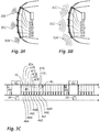
- Figures 3A to 3C shows a situation that can arise, for example, when parking the vehicle. In this situation it is necessary to recognize the environment as precisely as possible in order to avoid collisions.
- FIG. 3A shows, it is provided for this that three of the six sensor units, namely in the present case the sensor units 20A, 20C and 20E, are to transmit a signal.
- a command to this effect is transmitted to the relevant sensor units in the CRM phase 40.
- these sensor units 20A, 20C, 20E can also be informed in this phase 40 how the signal to be transmitted is to be individualized, for example by defining a particular transmission frequency so that the echo signals can later be distinguished.
- the sensor units 20A-20F always individualize the signal when it is transmitted using a parameter dependent on their bus identifier, for example by encoding the bus identifier in the signal to be transmitted.
- the control device 14 transmits to the sensor units 20B, 20D the bus identifier of one of the two virtual slaves described above, in this case the "7" and the "8" as an example.
- the commands in this regard tell the two sensor units 20B, 20D that they each have two time slots available for data transmission to the control device 14 in the subsequent PDCM phase, namely the fixed one specified their bus identifiers ("2" or "4") assigned and one variably assigned ("7” or "8").
- the control device After completion of the CRM phase 40, the control device increases the bus voltage in the manner already described to a value beyond the highest voltage usual for data transmission and thus initiates the power phase 43.
- the sensor units hereby charge their respective capacitors 23 and the selected sensor units 20A, 20C, 20E then each transmit their ultrasonic signal 30A, 30C, 30E.
- the control device 14 Using the first synchronization signal 45, the control device 14 initiates the data transmission from the sensor units 20A to 20E to the control device 14. First of all, all six sensor units 20A-20F send the recorded data of a first echo signal to the control device in their permanently assigned time slot 47A-47F. As soon as this has happened, the two sensor units 20B, 20D send the recorded data of the second echo signal which were recorded by them in the time slots 47G, 47H additionally assigned to them for this measuring cycle.
- the time slots are not sufficient to completely transmit the recorded data of an echo signal to the control device, so that the control device sends a second synchronization signal 45, which again gives each sensor unit 20A-20F the opportunity to convert the remaining data into their respective time slot 47A-47F.
- the sensor units 20B, 20D also transmit in the time slot 47G, 47H additionally assigned to them for this measurement cycle.
- the second example of the Figures 4A to 4C represents a driving situation that can arise in city traffic.
- the sensor units 20D and 20F that are to emit ultrasonic signals.
- the sensor unit 20A should also emit an ultrasonic signal by means of which the oncoming traffic can be observed.
- commands are therefore issued from the control device 14 to these sensor units 20A, 20D, 20F that they have to send out signals, possibly supplemented by parameters for the signal to be sent out, so that they remain distinguishable from one another.
- a command is sent to the sensor 20E, by means of which the time slot 47G of one of the two virtual slaves is assigned to this sensor, in this case the virtual slave with the bus identifier "7".
- the virtual slave with the bus identifier "8" and its time slot 47H are not assigned to any of the sensor units in this second example.
- the selected sensor units 20B, 20D, 20F now send their respective ultrasonic signals 32B, 32D, 32F in the power phase 43, as in FIG Figure 4A is made clear. These ultrasonic signals are in turn reflected on reflective surfaces and reach the sensor units as echo signals 33B, 33D, 33F.
- the sensor unit 20E then uses the time slot 47G, which is assigned to the bus identifier “7”, in order to transmit its larger amount of data to the control device 14 compared to the other sensor units.
- the specialty in this second example is that the time slot 47H, which is assigned to the bus identifier "8" and which was not assigned to any of the sensor units 20A to 20F, does not have to be waited for. After receiving the data of the time slot 47F with the bus identifier "7", the control unit 14 immediately sends the second synchronization signal 45, since it knows that it has assigned the bus identifier "8" and therefore no more data can be expected.
- the signal emitted by said sensor units 20B, 20F is reflected, it returns to the sensor units as echo signal 35B, 35F, sensor units 20A to 20C detecting echo signal 36B and sensor units 20D to 20F detecting echo signal 36F.
- the data transmission by the sensor units 20A to 20F is initiated. All sensor units 20A-20F transmit the recorded data in their respective time slot 47A-47F.
- the control device 14 sends the second synchronization signal 45 in order to receive the remaining data in the second time slots 47A-47F. The control device 14 then switches back to the CRM mode and thus initiates the next measurement cycle.
- the total of eight time slots 47A to 47H do not result in an extension of the measurement cycle in this third example, unless this is required by the amount of data.
- the third example also shows that the measuring cycle then if there is no increased amount of data, it is not extended compared to a conception of the sensor arrangement completely without virtual slaves
- the main advantage of the shortening of the measuring cycles according to the second and third example is a higher measuring frequency. While a lower measurement frequency can be tolerated in the parking situation of the first example due to the low speeds usually given here, in the city traffic situation of example 2 as well as the highway situation of example 3 and due to the higher speeds prevailing here, it is very advantageous that measurement cycles are shortened and the measuring frequency is increased
Landscapes
- Engineering & Computer Science (AREA)
- Remote Sensing (AREA)
- Radar, Positioning & Navigation (AREA)
- Physics & Mathematics (AREA)
- Computer Networks & Wireless Communication (AREA)
- General Physics & Mathematics (AREA)
- Signal Processing (AREA)
- Electromagnetism (AREA)
- Multimedia (AREA)
- Theoretical Computer Science (AREA)
- Acoustics & Sound (AREA)
- Measurement Of Velocity Or Position Using Acoustic Or Ultrasonic Waves (AREA)
- Arrangements For Transmission Of Measured Signals (AREA)
Claims (14)
- Procédé permettant de faire fonctionner un agencement de capteurs (12) dans un véhicule automobile sur la base d'un protocole DSI, ayant les particularités suivantes :a. l'agencement de capteurs (12) dispose d'au moins une unité de traitement (14) et d'au moins une unité de capteur active (20A-20F) dotée d'un émetteur (21) pour émettre un signal (30, 32, 34) et d'un récepteur (22) pour recevoir un signal d'écho (31, 33, 35) qui sont reliés l'un à l'autre par un bus (16) composé de deux lignes, etb. la communication entre l'unité de traitement (14) et l'unité de capteur active (20A-20F) est effectuée à plusieurs reprises dans une séquence ayant les phases partielles suivantes :∘ dans une phase de CRM, « Command and Response Mode », (40), une communication bidirectionnelle a lieu entre l'unité de traitement (14) et l'unité de capteur active (20A-20F),∘ dans une phase de puissance (43), un transfert d'énergie de l'unité de traitement (14) à l'unité de capteur active (20A-20F) a lieu, et∘ dans une phase de PDCM, « Periodic Data Collection Mode », (44), après un signal de synchronisation (45) envoyé par l'unité de traitement, une transmission de données unidirectionnelle de l'unité de capteur active (20A-20F) à l'unité de traitement (14) a lieu.
- Procédé selon la revendication 1, ayant la particularité supplémentaire suivante : ladite au moins une unité de capteur active (20A-20F) est réalisée sous la forme d'une unité de capteur à ultrasons (20A-20F) dotée d'un émetteur à ultrasons (21) et d'un récepteur à ultrasons (22).
- Procédé selon la revendication 2, ayant la particularité supplémentaire suivante : pendant la phase de puissance (43), l'émetteur (21) émet le signal (30, 32, 34) dont le signal d'écho (31, 33, 35) est ensuite capté par le récepteur (22).
- Procédé selon l'une quelconque des revendications 1 à 3, ayant la particularité supplémentaire suivante : l'unité de capteur active (20A-20F) dispose d'un accumulateur d'énergie (23) pour accumuler de l'énergie électrique et qui est chargé pendant la phase de puissance (43).
- Procédé selon l'une quelconque des revendications précédentes, ayant la particularité supplémentaire suivante : dans la phase de CRM (40), des données sont envoyées de l'unité de traitement (14) à l'unité de capteur active (20A-20F) qui comprennent des paramètres pour l'envoi du signal (30, 32, 34) et/ou qui comprennent des paramètres pour la réception du signal d'écho (31, 33, 35) au moyen du récepteur (22).
- Procédé permettant de faire fonctionner un agencement de capteurs (12) dans un véhicule automobile sur la base d'un protocole DSI, ayant les particularités suivantes :a. l'agencement de capteurs (12) dispose d'au moins une unité de traitement (14) et d'au moins deux unités de capteur actives (20A-20F) dotées d'un émetteur (21) pour émettre un signal (30, 32, 34) et d'un récepteur (22) pour recevoir un signal d'écho (31, 33, 35) qui sont reliés l'un à l'autre par un bus (16) composé de deux lignes, etb. la communication entre l'unité de traitement (14) et les unités de capteur actives (20A-20F) a lieu dans une séquence comprenant les phases partielles suivantes :∘ dans une phase de CRM, « Command and Response Mode », (40), une communication bidirectionnelle a lieu entre l'unité de traitement (14) et les unités de capteur actives (20A-20F) dans le cadre de laquelle l'unité de traitement (14) d'une des unités de capteur actives (20A-20F) associe par libération une tranche de temps complémentaire variable (47G, 47H) en plus d'une tranche de temps (47A-47F) associée de manière fixe aux unités de capteur actives, et∘ dans une phase de PDCM, « Periodic Data Collection Mode », (44), après un signal de synchronisation (45) envoyé par l'unité de traitement (14), une transmission de données unidirectionnelle dans différentes tranches de temps (45A-47H) des au moins deux unités de capteur actives (20A-20F) à l'unité de traitement (14) a lieu, ladite unité de capteur active (20A-20F) à laquelle la libération pour une tranche de temps complémentaire (47G, 47H) a été accordée précédemment dans la phase de CRM (40) envoyant des données à l'unité de traitement à la fois dans la tranche de temps (47A-47F) qui lui est associée de manière fixe et dans la tranche de temps complémentaire (47G, 47H) qui lui est associée.
- Procédé selon la revendication 6, ayant la particularité supplémentaire suivante : les unités de capteur actives (20A-20F) sont réalisées sous la forme d'unités de capteur à ultrasons (20A-20F) dotées d'un émetteur à ultrasons (21) et d'un récepteur à ultrasons (22), et dans la phase de CRM (40), un ordre d'envoyer respectivement un signal (30, 32, 34) est donné à au moins deux des unités de capteur actives (20A-20F), et l'association de la tranche de temps complémentaire (47G, 47H) à l'une des au moins deux unités de capteur actives (20A-20F) a lieu en fonction de celle des unités de capteur actives (20A-20F) qui recevra probablement des signaux d'écho (31, 33, 35) des au moins deux signaux envoyés (30, 32, 34) en raison de l'agencement des unités de capteur actives (20A-20F).
- Procédé selon l'une quelconque des revendications 6 et 7, ayant la particularité supplémentaire suivante : lors de la mise en service de l'agencement de capteurs (12), l'unité de traitement (14) envoie une information aux unités de capteur actives (20A-20F) concernant la position relative temporelle des tranches de temps (47A-47F) associées de manière fixe de chaque unité de capteur active (20A-20F) et de ladite au moins une tranche de temps complémentaire (47G, 47H) variable.
- Procédé selon l'une quelconque des revendications 6 à 8, ayant la particularité supplémentaire suivante : des positions relatives sont associées aux tranches de temps (47A-47H) dans un ordre selon lequel les tranches de temps (47A-47F) associées de manière fixe sont disposées temporellement avant les tranches de temps complémentaires (47G, 47H) pouvant être associées de manière variable.
- Procédé selon l'une quelconque des revendications 6 à 9, ayant la particularité supplémentaire suivante : l'association de la tranche de temps supplémentaire (47G, 47H) à l'une des unités de capteur actives (20A-20F) a lieu par la transmission d'un identifiant non attribué à une unité de capteur active réelle (20A-20F) .
- Procédé selon l'une quelconque des revendications précédentes, ayant au moins l'une des particularités supplémentaires suivantes : dans la phase de PDCM (44), l'unité de traitement (14) envoie une ou plusieurs fois un signal de synchronisation (45) qui est reçu par ladite au moins une unité de capteur active (20A-20F), dans lequel les unités de capteur actives (20A-20F), sur la base d'une information déjà stockée dans les unités de capteur actives (20A-20F) ou transmise par l'unité de traitement concernant la position relative temporelle des tranches de temps (47A-47H) de chaque unité de capteur active (20A-20F), commencent ensuite la transmission de données à l'unité de traitement (14), et/ou dans la phase de CRM (40), l'unité de traitement (14) envoie des ordres (41) d'une longueur de 32 bits, adressés à l'une des unités de capteur actives (20A-20F), dans lequel de préférence l'unité de capteur active (20A-20F) adressée envoie ensuite une réponse (42) d'une longueur de 32 bits et/ou la transmission de données de l'unité de traitement (14) aux unités de capteur actives (20A-20F) a lieu par modulation en tension, dans lequel de préférence un codage Manchester et/ou deux niveaux de tension VLow de 2 V [+/-0,25 V] et VHigh de 4 V [+/-0,5 V] sont utilisés et/ou la transmission de données a lieu d'une unité de capteur active (20A-20F) à l'unité de traitement (14), par modulation en intensité de courant, dans lequel de préférence les données sont codées en intensités de courant de trois niveaux discrets et de préférence à distance égales les uns des autres, et/ou dans la phase de puissance (43) l'unité de traitement (14) augmente la tension VIdle appliquée au bus (16) à au moins 6 V.
- Agencement de capteurs (12), en particulier agencement de capteurs à ultrasons (12) pour un véhicule automobile (10), ayant les particularités suivantes :a. l'agencement de capteurs (12) dispose d'au moins une instance centrale (14) et d'au moins une unité de capteur active (20A-20F) qui sont reliées l'une à l'autre par un bus (16) composé de deux lignes, etb. chaque unité de capteur active (20A-20F) comprend de préférence un émetteur à ultrasons (21) et un récepteur à ultrasons (22), etc. l'agencement de capteurs (12) est réalisé pour fonctionner selon l'un des procédés des revendications précédentes.
- Système d'assistance au conducteur pour un véhicule, ayant la particularité suivante : le système d'assistance au conducteur dispose d'un agencement de capteurs (12) selon la revendication 12.
- Véhicule (10), ayant la particularité suivante : le véhicule (10) dispose d'un système d'assistance au conducteur selon la revendication 13, dans lequel de préférence l'agencement de capteurs (12) est réalisé comme un agencement de capteurs à ultrasons (12) au niveau d'un pare-chocs du véhicule (10).
Applications Claiming Priority (2)
| Application Number | Priority Date | Filing Date | Title |
|---|---|---|---|
| DE102017103117.0A DE102017103117A1 (de) | 2017-02-16 | 2017-02-16 | Verfahren zum Betrieb einer Sensoranordnung auf Basis eines DSI-Protokolls in einem Kraftfahrzeug sowie eine entsprechende Sensoranordnung in einem Kraftfahrzeug |
| PCT/EP2018/053758 WO2018149908A1 (fr) | 2017-02-16 | 2018-02-15 | Procédé de fonctionnement d'un dispositif de détection sur la base d'un protocole dsi et dispositif de détection correspondant |
Publications (2)
| Publication Number | Publication Date |
|---|---|
| EP3583584A1 EP3583584A1 (fr) | 2019-12-25 |
| EP3583584B1 true EP3583584B1 (fr) | 2021-01-20 |
Family
ID=61244595
Family Applications (1)
| Application Number | Title | Priority Date | Filing Date |
|---|---|---|---|
| EP18705894.6A Active EP3583584B1 (fr) | 2017-02-16 | 2018-02-15 | Procédé de fonctionnement d'un dispositif de détection sur la base d'un protocole dsi et dispositif de détection correspondant |
Country Status (4)
| Country | Link |
|---|---|
| US (1) | US11313964B2 (fr) |
| EP (1) | EP3583584B1 (fr) |
| DE (1) | DE102017103117A1 (fr) |
| WO (1) | WO2018149908A1 (fr) |
Families Citing this family (13)
| Publication number | Priority date | Publication date | Assignee | Title |
|---|---|---|---|---|
| DE102017118565A1 (de) * | 2017-08-15 | 2019-02-21 | Valeo Schalter Und Sensoren Gmbh | Verfahren zum Betreiben einer Sensoranordnung in einem Kraftfahrzeug auf Basis eines DSI-Protokolls |
| DE102018206535A1 (de) * | 2018-04-27 | 2019-10-31 | Robert Bosch Gmbh | Radarsensoreinrichtung |
| DE102018114225B4 (de) | 2018-06-14 | 2026-01-15 | Valeo Schalter Und Sensoren Gmbh | Verfahren zum Betreiben einer Sensoranordnung in einem Kraftfahrzeug auf Basis eines DSI-Protokolls |
| DE102018119533A1 (de) | 2018-08-10 | 2020-02-13 | Valeo Schalter Und Sensoren Gmbh | Verfahren und Vorrichtung zum Bereitstellen eines digitalen Sensorsignals eines Ultraschallsensors |
| EP3624510A1 (fr) * | 2018-09-17 | 2020-03-18 | KNORR-BREMSE Systeme für Nutzfahrzeuge GmbH | Appareil et procédé pour synchroniser des n uds d'extrémité |
| JP7165882B2 (ja) * | 2019-03-14 | 2022-11-07 | パナソニックIpマネジメント株式会社 | 通信装置および通信システム |
| DE102019112230A1 (de) * | 2019-05-10 | 2020-11-12 | Stego-Holding Gmbh | Sensorhub, Sensorsystem, Verfahren zum Übertragen von Sensorsignalen und computerlesbares-Speichermedium |
| JP7245993B2 (ja) * | 2019-07-18 | 2023-03-27 | パナソニックIpマネジメント株式会社 | 通信装置および通信システム |
| USD966201S1 (en) | 2019-11-11 | 2022-10-11 | Stego-Holding Gmbh | Junction box for data conductors |
| US12052100B2 (en) * | 2021-02-01 | 2024-07-30 | Semiconductor Components Industries, Llc | DSI3 bus with enhanced robustness |
| DE102022209468A1 (de) | 2022-09-12 | 2024-03-14 | Robert Bosch Gesellschaft mit beschränkter Haftung | Ultraschallsystem für ein Fahrzeug und Fahrzeug |
| CN116389945A (zh) * | 2023-03-13 | 2023-07-04 | 黑芝麻科技公司 | 多传感器系统的同步 |
| DE102023117757A1 (de) | 2023-07-05 | 2025-01-09 | Bayerische Motoren Werke Aktiengesellschaft | Sensornetzwerk mit einer fehlerdiagnosevorrichtung, verfahren zur fehlerdiagnose in einem sensornetzwerk, computerlesbares speichermedium |
Family Cites Families (8)
| Publication number | Priority date | Publication date | Assignee | Title |
|---|---|---|---|---|
| US7746114B2 (en) | 2007-11-14 | 2010-06-29 | Denso Corporation | Bus switch and electronic switch |
| WO2010001200A1 (fr) | 2008-06-30 | 2010-01-07 | Freescale Semiconductor, Inc. | Gestion des anomalies pour bus de communication |
| WO2010013097A1 (fr) | 2008-07-31 | 2010-02-04 | Freescale Semiconductor, Inc. | Appareil tampon, circuit intégré et procédé de réduction d'une partie d'une oscillation d'un signal de sortie |
| JP5045797B2 (ja) * | 2010-02-24 | 2012-10-10 | 株式会社デンソー | 通信用スレーブ |
| DE102010002679B4 (de) | 2010-03-09 | 2023-01-05 | Robert Bosch Gmbh | Verfahren zur Versorgung mindestens eines Busteilnehmers |
| DE102012222891A1 (de) | 2012-12-12 | 2014-06-12 | Robert Bosch Gmbh | Fahrassistenzsystem umfassend eine Sensoreinheit |
| US9588155B2 (en) | 2014-10-16 | 2017-03-07 | Freescale Semiconductor, Inc. | Current detection circuit with over-current protection |
| JP6573104B2 (ja) * | 2015-06-05 | 2019-09-11 | ローム株式会社 | 指標導出装置、ウェアラブル機器及び携帯機器 |
-
2017
- 2017-02-16 DE DE102017103117.0A patent/DE102017103117A1/de not_active Withdrawn
-
2018
- 2018-02-15 WO PCT/EP2018/053758 patent/WO2018149908A1/fr not_active Ceased
- 2018-02-15 US US16/486,242 patent/US11313964B2/en active Active
- 2018-02-15 EP EP18705894.6A patent/EP3583584B1/fr active Active
Non-Patent Citations (1)
| Title |
|---|
| None * |
Also Published As
| Publication number | Publication date |
|---|---|
| WO2018149908A1 (fr) | 2018-08-23 |
| US11313964B2 (en) | 2022-04-26 |
| DE102017103117A1 (de) | 2018-08-16 |
| EP3583584A1 (fr) | 2019-12-25 |
| US20200241130A1 (en) | 2020-07-30 |
Similar Documents
| Publication | Publication Date | Title |
|---|---|---|
| EP3583584B1 (fr) | Procédé de fonctionnement d'un dispositif de détection sur la base d'un protocole dsi et dispositif de détection correspondant | |
| EP2263102B1 (fr) | Système d assistance au conducteur à base d ultrasons | |
| EP3669550B1 (fr) | Procédé pour faire fonctionner un ensemble de détection dans un véhicule à moteur sur la base d'un protocole dsi | |
| DE102017124645A1 (de) | Bordeigenes Netzwerksystem, Kommunikationssteuerungsverfahren in dem bordeigenen Netzwerksystem und bordeigenes Gateway | |
| EP2359539B1 (fr) | Protocole de transmission de données | |
| EP0406718B1 (fr) | Méthode de communication pour un bus de données monofil dans un véhicule automobile | |
| EP1979790B1 (fr) | Procédé et dispositif d'attribution d'adresses dans un système comportant plusieurs unités de générateur disposées de façon parallèle | |
| DE102011012379A1 (de) | Verfahren und Radar-Sensoranordnung zur Detektion von Ort und Geschwindigkeit von Objekten relativ zu einem Fahrzeug | |
| WO2007057071A1 (fr) | Procede pour faire fonctionner un systeme de detection, systeme de detection et module de detection | |
| DE102008000571A1 (de) | Adressierung von Sende- und Empfangseinheiten einer Ultraschallabstandsmesseinrichtung | |
| EP2549295B1 (fr) | Dispositif de capteur pour un véhicule automobile, véhicule automobile et procédé de fonctionnement d'au moins deux capteurs dans un véhicule automobile | |
| DE102013002648B3 (de) | Master-Busgerät für einen Fahrzeugkommunikationsbus eines Kraftwagens | |
| EP1298451B1 (fr) | Dispositif pour évaluer l'environnement | |
| EP2788785B1 (fr) | Système de capteurs servant à faire fonctionner un système de capteurs | |
| EP1979793B1 (fr) | Procédé et dispositif d'attribution d'adresses dans un système comportant plusieurs unités de générateur disposées de façon parallèle | |
| EP2560845B1 (fr) | Procédé pour faire fonctionner des appareils de commande de propulsion dans un véhicule à moteur, et véhicule à moteur correspondant | |
| EP2101190B1 (fr) | Attribution des adresses aux unités de transmission et réception d'un système à ultrasons | |
| EP2527869B1 (fr) | Dispositif de capteur pour un véhicule automobile, véhicule automobile et procédé de fonctionnement d'au moins deux capteurs dans un véhicule automobile | |
| DE102006019833A1 (de) | Einrichtung zur Entdeckung eines Hindernisses | |
| EP2772043B1 (fr) | Procédé d'attribution automatique d'un indicatif spécifique à chaque capteur d'une pluralité de capteurs d'un véhicule automobile, système et dispositif informatique | |
| EP3230765A1 (fr) | Procédé pour faire fonctionner un dispositif de détection pour véhicule automobile avec sélection de données de capteur, dispositif de détection et véhicule automobile | |
| DE102017204394A1 (de) | Selbstorganisierende Sensoranordnung und Verfahren zu ihrem Betrieb, insbesondere für ein Kraftfahrzeug mit PSI5-Schnittstelle | |
| DE102018112587A1 (de) | Verfahren zum Betreiben einer Sensoranordnung in einem Kraftfahrzeug auf Basis eines DSI-Protokolls | |
| EP2265972B1 (fr) | Adressage d'unités émettrices et réceptrices d'une installation de mesure de distance à ultrasons | |
| EP1478943A1 (fr) | Procede et dispositif de transmission de donnees de mesure par l'intermediaire d'un systeme can-bus dans un systeme de detection de donnees pour vehicules a moteur |
Legal Events
| Date | Code | Title | Description |
|---|---|---|---|
| STAA | Information on the status of an ep patent application or granted ep patent |
Free format text: STATUS: UNKNOWN |
|
| STAA | Information on the status of an ep patent application or granted ep patent |
Free format text: STATUS: THE INTERNATIONAL PUBLICATION HAS BEEN MADE |
|
| PUAI | Public reference made under article 153(3) epc to a published international application that has entered the european phase |
Free format text: ORIGINAL CODE: 0009012 |
|
| STAA | Information on the status of an ep patent application or granted ep patent |
Free format text: STATUS: REQUEST FOR EXAMINATION WAS MADE |
|
| 17P | Request for examination filed |
Effective date: 20190723 |
|
| AK | Designated contracting states |
Kind code of ref document: A1 Designated state(s): AL AT BE BG CH CY CZ DE DK EE ES FI FR GB GR HR HU IE IS IT LI LT LU LV MC MK MT NL NO PL PT RO RS SE SI SK SM TR |
|
| AX | Request for extension of the european patent |
Extension state: BA ME |
|
| DAV | Request for validation of the european patent (deleted) | ||
| DAX | Request for extension of the european patent (deleted) | ||
| GRAP | Despatch of communication of intention to grant a patent |
Free format text: ORIGINAL CODE: EPIDOSNIGR1 |
|
| STAA | Information on the status of an ep patent application or granted ep patent |
Free format text: STATUS: GRANT OF PATENT IS INTENDED |
|
| INTG | Intention to grant announced |
Effective date: 20200907 |
|
| GRAS | Grant fee paid |
Free format text: ORIGINAL CODE: EPIDOSNIGR3 |
|
| GRAA | (expected) grant |
Free format text: ORIGINAL CODE: 0009210 |
|
| STAA | Information on the status of an ep patent application or granted ep patent |
Free format text: STATUS: THE PATENT HAS BEEN GRANTED |
|
| AK | Designated contracting states |
Kind code of ref document: B1 Designated state(s): AL AT BE BG CH CY CZ DE DK EE ES FI FR GB GR HR HU IE IS IT LI LT LU LV MC MK MT NL NO PL PT RO RS SE SI SK SM TR |
|
| REG | Reference to a national code |
Ref country code: GB Ref legal event code: FG4D Free format text: NOT ENGLISH |
|
| REG | Reference to a national code |
Ref country code: CH Ref legal event code: EP |
|
| REG | Reference to a national code |
Ref country code: DE Ref legal event code: R096 Ref document number: 502018003722 Country of ref document: DE |
|
| REG | Reference to a national code |
Ref country code: AT Ref legal event code: REF Ref document number: 1357056 Country of ref document: AT Kind code of ref document: T Effective date: 20210215 |
|
| REG | Reference to a national code |
Ref country code: IE Ref legal event code: FG4D Free format text: LANGUAGE OF EP DOCUMENT: GERMAN |
|
| REG | Reference to a national code |
Ref country code: SE Ref legal event code: TRGR |
|
| REG | Reference to a national code |
Ref country code: NL Ref legal event code: MP Effective date: 20210120 |
|
| REG | Reference to a national code |
Ref country code: LT Ref legal event code: MG9D |
|
| PG25 | Lapsed in a contracting state [announced via postgrant information from national office to epo] |
Ref country code: GR Free format text: LAPSE BECAUSE OF FAILURE TO SUBMIT A TRANSLATION OF THE DESCRIPTION OR TO PAY THE FEE WITHIN THE PRESCRIBED TIME-LIMIT Effective date: 20210421 Ref country code: HR Free format text: LAPSE BECAUSE OF FAILURE TO SUBMIT A TRANSLATION OF THE DESCRIPTION OR TO PAY THE FEE WITHIN THE PRESCRIBED TIME-LIMIT Effective date: 20210120 Ref country code: FI Free format text: LAPSE BECAUSE OF FAILURE TO SUBMIT A TRANSLATION OF THE DESCRIPTION OR TO PAY THE FEE WITHIN THE PRESCRIBED TIME-LIMIT Effective date: 20210120 Ref country code: BG Free format text: LAPSE BECAUSE OF FAILURE TO SUBMIT A TRANSLATION OF THE DESCRIPTION OR TO PAY THE FEE WITHIN THE PRESCRIBED TIME-LIMIT Effective date: 20210420 Ref country code: LT Free format text: LAPSE BECAUSE OF FAILURE TO SUBMIT A TRANSLATION OF THE DESCRIPTION OR TO PAY THE FEE WITHIN THE PRESCRIBED TIME-LIMIT Effective date: 20210120 Ref country code: PT Free format text: LAPSE BECAUSE OF FAILURE TO SUBMIT A TRANSLATION OF THE DESCRIPTION OR TO PAY THE FEE WITHIN THE PRESCRIBED TIME-LIMIT Effective date: 20210520 Ref country code: NO Free format text: LAPSE BECAUSE OF FAILURE TO SUBMIT A TRANSLATION OF THE DESCRIPTION OR TO PAY THE FEE WITHIN THE PRESCRIBED TIME-LIMIT Effective date: 20210420 |
|
| PG25 | Lapsed in a contracting state [announced via postgrant information from national office to epo] |
Ref country code: LV Free format text: LAPSE BECAUSE OF FAILURE TO SUBMIT A TRANSLATION OF THE DESCRIPTION OR TO PAY THE FEE WITHIN THE PRESCRIBED TIME-LIMIT Effective date: 20210120 Ref country code: RS Free format text: LAPSE BECAUSE OF FAILURE TO SUBMIT A TRANSLATION OF THE DESCRIPTION OR TO PAY THE FEE WITHIN THE PRESCRIBED TIME-LIMIT Effective date: 20210120 Ref country code: PL Free format text: LAPSE BECAUSE OF FAILURE TO SUBMIT A TRANSLATION OF THE DESCRIPTION OR TO PAY THE FEE WITHIN THE PRESCRIBED TIME-LIMIT Effective date: 20210120 |
|
| PG25 | Lapsed in a contracting state [announced via postgrant information from national office to epo] |
Ref country code: IS Free format text: LAPSE BECAUSE OF FAILURE TO SUBMIT A TRANSLATION OF THE DESCRIPTION OR TO PAY THE FEE WITHIN THE PRESCRIBED TIME-LIMIT Effective date: 20210520 |
|
| REG | Reference to a national code |
Ref country code: DE Ref legal event code: R097 Ref document number: 502018003722 Country of ref document: DE |
|
| REG | Reference to a national code |
Ref country code: BE Ref legal event code: MM Effective date: 20210228 |
|
| PG25 | Lapsed in a contracting state [announced via postgrant information from national office to epo] |
Ref country code: LU Free format text: LAPSE BECAUSE OF NON-PAYMENT OF DUE FEES Effective date: 20210215 Ref country code: MC Free format text: LAPSE BECAUSE OF FAILURE TO SUBMIT A TRANSLATION OF THE DESCRIPTION OR TO PAY THE FEE WITHIN THE PRESCRIBED TIME-LIMIT Effective date: 20210120 Ref country code: LI Free format text: LAPSE BECAUSE OF NON-PAYMENT OF DUE FEES Effective date: 20210228 Ref country code: CZ Free format text: LAPSE BECAUSE OF FAILURE TO SUBMIT A TRANSLATION OF THE DESCRIPTION OR TO PAY THE FEE WITHIN THE PRESCRIBED TIME-LIMIT Effective date: 20210120 Ref country code: EE Free format text: LAPSE BECAUSE OF FAILURE TO SUBMIT A TRANSLATION OF THE DESCRIPTION OR TO PAY THE FEE WITHIN THE PRESCRIBED TIME-LIMIT Effective date: 20210120 Ref country code: CH Free format text: LAPSE BECAUSE OF NON-PAYMENT OF DUE FEES Effective date: 20210228 Ref country code: SM Free format text: LAPSE BECAUSE OF FAILURE TO SUBMIT A TRANSLATION OF THE DESCRIPTION OR TO PAY THE FEE WITHIN THE PRESCRIBED TIME-LIMIT Effective date: 20210120 |
|
| PLBE | No opposition filed within time limit |
Free format text: ORIGINAL CODE: 0009261 |
|
| STAA | Information on the status of an ep patent application or granted ep patent |
Free format text: STATUS: NO OPPOSITION FILED WITHIN TIME LIMIT |
|
| PG25 | Lapsed in a contracting state [announced via postgrant information from national office to epo] |
Ref country code: DK Free format text: LAPSE BECAUSE OF FAILURE TO SUBMIT A TRANSLATION OF THE DESCRIPTION OR TO PAY THE FEE WITHIN THE PRESCRIBED TIME-LIMIT Effective date: 20210120 Ref country code: SK Free format text: LAPSE BECAUSE OF FAILURE TO SUBMIT A TRANSLATION OF THE DESCRIPTION OR TO PAY THE FEE WITHIN THE PRESCRIBED TIME-LIMIT Effective date: 20210120 Ref country code: RO Free format text: LAPSE BECAUSE OF FAILURE TO SUBMIT A TRANSLATION OF THE DESCRIPTION OR TO PAY THE FEE WITHIN THE PRESCRIBED TIME-LIMIT Effective date: 20210120 |
|
| 26N | No opposition filed |
Effective date: 20211021 |
|
| PG25 | Lapsed in a contracting state [announced via postgrant information from national office to epo] |
Ref country code: IE Free format text: LAPSE BECAUSE OF NON-PAYMENT OF DUE FEES Effective date: 20210215 Ref country code: AL Free format text: LAPSE BECAUSE OF FAILURE TO SUBMIT A TRANSLATION OF THE DESCRIPTION OR TO PAY THE FEE WITHIN THE PRESCRIBED TIME-LIMIT Effective date: 20210120 Ref country code: ES Free format text: LAPSE BECAUSE OF FAILURE TO SUBMIT A TRANSLATION OF THE DESCRIPTION OR TO PAY THE FEE WITHIN THE PRESCRIBED TIME-LIMIT Effective date: 20210120 |
|
| PG25 | Lapsed in a contracting state [announced via postgrant information from national office to epo] |
Ref country code: SI Free format text: LAPSE BECAUSE OF FAILURE TO SUBMIT A TRANSLATION OF THE DESCRIPTION OR TO PAY THE FEE WITHIN THE PRESCRIBED TIME-LIMIT Effective date: 20210120 |
|
| PG25 | Lapsed in a contracting state [announced via postgrant information from national office to epo] |
Ref country code: IS Free format text: LAPSE BECAUSE OF FAILURE TO SUBMIT A TRANSLATION OF THE DESCRIPTION OR TO PAY THE FEE WITHIN THE PRESCRIBED TIME-LIMIT Effective date: 20210520 |
|
| PG25 | Lapsed in a contracting state [announced via postgrant information from national office to epo] |
Ref country code: BE Free format text: LAPSE BECAUSE OF NON-PAYMENT OF DUE FEES Effective date: 20210228 |
|
| PG25 | Lapsed in a contracting state [announced via postgrant information from national office to epo] |
Ref country code: NL Free format text: LAPSE BECAUSE OF NON-PAYMENT OF DUE FEES Effective date: 20210120 Ref country code: CY Free format text: LAPSE BECAUSE OF FAILURE TO SUBMIT A TRANSLATION OF THE DESCRIPTION OR TO PAY THE FEE WITHIN THE PRESCRIBED TIME-LIMIT Effective date: 20210120 |
|
| P01 | Opt-out of the competence of the unified patent court (upc) registered |
Effective date: 20230528 |
|
| PG25 | Lapsed in a contracting state [announced via postgrant information from national office to epo] |
Ref country code: HU Free format text: LAPSE BECAUSE OF FAILURE TO SUBMIT A TRANSLATION OF THE DESCRIPTION OR TO PAY THE FEE WITHIN THE PRESCRIBED TIME-LIMIT; INVALID AB INITIO Effective date: 20180215 |
|
| REG | Reference to a national code |
Ref country code: AT Ref legal event code: MM01 Ref document number: 1357056 Country of ref document: AT Kind code of ref document: T Effective date: 20230215 |
|
| PG25 | Lapsed in a contracting state [announced via postgrant information from national office to epo] |
Ref country code: AT Free format text: LAPSE BECAUSE OF NON-PAYMENT OF DUE FEES Effective date: 20230215 |
|
| PG25 | Lapsed in a contracting state [announced via postgrant information from national office to epo] |
Ref country code: MK Free format text: LAPSE BECAUSE OF FAILURE TO SUBMIT A TRANSLATION OF THE DESCRIPTION OR TO PAY THE FEE WITHIN THE PRESCRIBED TIME-LIMIT Effective date: 20210120 Ref country code: AT Free format text: LAPSE BECAUSE OF NON-PAYMENT OF DUE FEES Effective date: 20230215 |
|
| PG25 | Lapsed in a contracting state [announced via postgrant information from national office to epo] |
Ref country code: MT Free format text: LAPSE BECAUSE OF FAILURE TO SUBMIT A TRANSLATION OF THE DESCRIPTION OR TO PAY THE FEE WITHIN THE PRESCRIBED TIME-LIMIT Effective date: 20210120 |
|
| PG25 | Lapsed in a contracting state [announced via postgrant information from national office to epo] |
Ref country code: TR Free format text: LAPSE BECAUSE OF FAILURE TO SUBMIT A TRANSLATION OF THE DESCRIPTION OR TO PAY THE FEE WITHIN THE PRESCRIBED TIME-LIMIT Effective date: 20210120 |
|
| PGFP | Annual fee paid to national office [announced via postgrant information from national office to epo] |
Ref country code: SE Payment date: 20260219 Year of fee payment: 9 |
|
| PGFP | Annual fee paid to national office [announced via postgrant information from national office to epo] |
Ref country code: GB Payment date: 20260219 Year of fee payment: 9 |
|
| PGFP | Annual fee paid to national office [announced via postgrant information from national office to epo] |
Ref country code: DE Payment date: 20260206 Year of fee payment: 9 |
|
| PGFP | Annual fee paid to national office [announced via postgrant information from national office to epo] |
Ref country code: AT Payment date: 20260410 Year of fee payment: 5 |
|
| PGFP | Annual fee paid to national office [announced via postgrant information from national office to epo] |
Ref country code: IT Payment date: 20260209 Year of fee payment: 9 |
|
| PGFP | Annual fee paid to national office [announced via postgrant information from national office to epo] |
Ref country code: FR Payment date: 20260227 Year of fee payment: 9 |