EP3583668B1 - Dispositif de dissipation de la chaleur pour armoire électrique - Google Patents
Dispositif de dissipation de la chaleur pour armoire électrique Download PDFInfo
- Publication number
- EP3583668B1 EP3583668B1 EP18717502.1A EP18717502A EP3583668B1 EP 3583668 B1 EP3583668 B1 EP 3583668B1 EP 18717502 A EP18717502 A EP 18717502A EP 3583668 B1 EP3583668 B1 EP 3583668B1
- Authority
- EP
- European Patent Office
- Prior art keywords
- air
- switch cabinet
- housing
- cabinet housing
- rear wall
- Prior art date
- Legal status (The legal status is an assumption and is not a legal conclusion. Google has not performed a legal analysis and makes no representation as to the accuracy of the status listed.)
- Active
Links
Images


Classifications
-
- H—ELECTRICITY
- H02—GENERATION; CONVERSION OR DISTRIBUTION OF ELECTRIC POWER
- H02B—BOARDS, SUBSTATIONS OR SWITCHING ARRANGEMENTS FOR THE SUPPLY OR DISTRIBUTION OF ELECTRIC POWER
- H02B1/00—Frameworks, boards, panels, desks, casings; Details of substations or switching arrangements
- H02B1/56—Cooling; Ventilation
- H02B1/565—Cooling; Ventilation for cabinets
-
- H—ELECTRICITY
- H02—GENERATION; CONVERSION OR DISTRIBUTION OF ELECTRIC POWER
- H02B—BOARDS, SUBSTATIONS OR SWITCHING ARRANGEMENTS FOR THE SUPPLY OR DISTRIBUTION OF ELECTRIC POWER
- H02B1/00—Frameworks, boards, panels, desks, casings; Details of substations or switching arrangements
- H02B1/56—Cooling; Ventilation
-
- H—ELECTRICITY
- H05—ELECTRIC TECHNIQUES NOT OTHERWISE PROVIDED FOR
- H05K—PRINTED CIRCUITS; CASINGS OR CONSTRUCTIONAL DETAILS OF ELECTRIC APPARATUS; MANUFACTURE OF ASSEMBLAGES OF ELECTRICAL COMPONENTS
- H05K7/00—Constructional details common to different types of electric apparatus
- H05K7/20—Modifications to facilitate cooling, ventilating, or heating
- H05K7/20536—Modifications to facilitate cooling, ventilating, or heating for racks or cabinets of standardised dimensions, e.g. electronic racks for aircraft or telecommunication equipment
- H05K7/20554—Forced ventilation of a gaseous coolant
- H05K7/20572—Forced ventilation of a gaseous coolant within cabinets for removing heat from sub-racks, e.g. plenum
Definitions
- the invention is based on a heat dissipation arrangement for a switchgear cabinet, which has a switchgear cabinet housing and an assembly housing accommodated in the interior thereof and mounted on a rear wall of the switchgear cabinet housing for receiving at least one component having a thermal power loss.
- the module housing has at least one fan, a cooling air inlet and a warm air outlet, cooling air being led out of the control cabinet housing into the module housing, through the module housing and out via the hot air outlet as heated cooling air out of the module housing via the fan.
- a cooling arrangement is from the DE 10 2007 040 594 A1 known.
- Further arrangements for cooling electrical components arranged in switch cabinets are in the US20100134972 A1 and US20160234974 A1 described.
- a compressor circuit for example a refrigeration machine, which is at least active when passive cooling of the Module housing in air recirculation mode, in which air is blown from the inside of the control cabinet housing into the module housing and blown back into the interior of the control cabinet as heated air, is insufficient.
- a compressor circuit for example a refrigeration machine
- This is always the case when the ambient temperature of the control cabinet housing is so high that the temperature difference between the interior of the control cabinet and the surroundings of the control cabinet housing required for dissipative cooling of the air absorbed in the interior of the control cabinet is not present.
- Compressor-operated cooling circuits or cooling circuits that are equipped with an active air / air heat exchanger, however, have a comparatively high energy consumption.
- the hot air outlet of the module housing opens into a hot air inlet of an air duct in the rear wall of the control cabinet housing, the air duct being guided through the rear wall and thermally coupled to and / or limited by an outer side of the rear wall , and wherein at least one cooling air outlet of the air duct opens into the interior of the control cabinet housing.
- the rear wall has the function of a heat exchanger, in which air to be warmed via the air duct is led through the rear wall and the air duct is thermally coupled to an outside of the rear wall, the dissipative cooling capacity of the control cabinet housing is compared to that from the State-of-the-art control cabinet housings increased, so that even for smaller differences ⁇ T between the control cabinet interior temperature and ambient temperature, sufficient cooling of the air contained in the control cabinet housing is still ensured and, accordingly, the use of energy-inefficient means for cooling, in particular on refrigeration machines and the like, can be dispensed with.
- the warm air inlet can be arranged a vertical distance above the cooling air outlet. It can thereby be achieved that the air to be cooled is guided essentially in the vertical direction through the rear wall and, in particular, is introduced back into the interior of the control cabinet housing in a lower region of the control cabinet housing, in order, for example, to use the underside of the module housing as cooled air via the cooling air inlet of the Module housing to be sucked.
- the air duct can immediately follow the warm air inlet in the air flow direction through the air duct or have a further warm air outlet associated therewith, which is open directly or indirectly to the surroundings of the control cabinet housing. This enables a part of the warm air to be blown out of the control cabinet housing due to a local air overpressure in the air duct.
- the further warm air outlet can open into a dormer window of the control cabinet housing, which in turn is vented to the surroundings of the control cabinet housing.
- the air duct can directly precede the cooling air outlet in the air flow direction through the air duct or have a further cooling air inlet associated therewith, which is open to the surroundings of the control cabinet housing. This makes it possible, in accordance with the Venturi effect, for cool air to be drawn into the air duct from the switch cabinet environment due to the cooled warm air flowing past the cooling air inlet.
- the further cooling air inlet can open into a base of the control cabinet housing below the interior, the base in turn being ventilated to the surroundings of the control cabinet housing.
- the air duct is meandering through the rear wall.
- the rear wall can have an inside facing the interior of the control cabinet housing and an outside arranged at a distance from the inside and facing the surroundings of the control cabinet housing, the air duct being delimited from the outside and from the inside.
- the rear wall can, for example, be double-walled, with two parallel spaced sides, a first side forming the inside and a second side forming the outside.
- the air duct can be delimited in the direction perpendicular to the rear wall by the outside and the inside.
- Air guiding elements can be accommodated between the inside and the outside of the rear wall, which prevent the air guided through the rear wall from getting from the warm air inlet to the cooling air outlet in the shortest possible way, so that the effective residence time of the cooling air in the rear wall increases for a given air flow rate and thus the heat exchange of the air conducted through the rear wall to the surroundings of the control cabinet housing is correspondingly improved over the entire surface of the rear wall.
- At least one air guiding element can extend between the inside and the outside and adjacent to it, via which the air guided through the air duct is guided in a meandering manner.
- a plurality of parallel and horizontal air guiding elements can extend between the inside and the outside, the air guiding elements delimiting the air duct between them, extending alternately starting from opposite end faces of the rear wall and each reaching a distance up to the opposite end face.
- part of the warm air is preferably released into the environment.
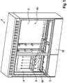
- the in the Figures 1 to 3 The heat dissipation arrangement shown is a so-called multifunction housing, which is used in particular for telecommunications applications.
- the control cabinet housing 1 has in its interior 2 a module housing 4, within which components which have a power loss and require cooling are accommodated. These components can be, for example, the components of an MSAN (Multi Service Access Node).
- MSAN Multi Service Access Node
- the module housing 4 has at least one fan (not shown), via which cooling air is blown into the module housing 4 from the interior of the control cabinet via at least one cooling air inlet 5.
- the cooling air inlet 5 is arranged on an underside of the module housing 4.
- the module housing 4 has a warm air outlet 6, which opens out via an inner side 13 into a rear wall 3 designed as a double wall, so that the hot air from the module housing 4 directly into an intermediate space between the inner side 13 and the outer side 9 the rear wall 3 is initiated.
- the air duct 8 Immediately after the warm air has entered the air duct 8 via the warm air inlet 7, the air duct 8 initially extends in a horizontal direction, so that the warm air runs along the upper end of the Rear wall 3 and immediately below a dormer 11 of the control cabinet housing 1 is perpendicular to the opposite side walls 16 or perpendicular to the end faces 15 of the rear wall 3.
- the air duct 8 has a further warm air outlet 6.1 directly downstream of the warm air inlet in the air flow direction, which opens into the dormer 11, so that at least some of the warm air flowing into the air duct 8 via the warm air inlet 7 flows into the duct via the further warm air inlet 6.1 Roof dormer 11 and can escape into the surroundings of the control cabinet housing 1.
- the cooled warm air is guided past a plurality of cooling air inlets 5.1, which are open to the surroundings of the control cabinet housing 1, before they enter the interior 2 of the control cabinet 1 via a plurality of cooling air outlets 10. Since the cooled air moves essentially parallel to the opening cross section of the further cooling air inlets 5.1, cool ambient air is sucked into the air duct 8 via the further cooling air inlets 5.1 due to the Venturi effect and transported back into the interior 2 of the control cabinet housing 1 with the cooled warm air. An additional cooling capacity is provided in this way.
- the further cooling air inlets 5.1 can open into the base 12 of the control cabinet housing 1 below the interior 2, the base 12 in turn being ventilated to the surroundings of the control cabinet housing 1.
- the plurality of parallel and horizontal air guiding elements 14 extend between the inside 13 and the outside 9, the air guiding elements 14 between them delimiting the air duct 8 in the vertical direction.
- the air guiding elements 14 continue to extend alternately starting from opposite end faces 15 of the rear wall 3 and each reaching a distance up to the opposite end face. In this way it is achieved that between the inner side 13 and the outer side 9 and between the adjacent air guiding elements the air duct 8 is formed, through which the warm air entering via the warm air inlet 7 is led in a meandering manner for the most effective cooling possible to the cooling air outlets 10 of the air duct 8 .
Landscapes
- Engineering & Computer Science (AREA)
- Power Engineering (AREA)
- Aviation & Aerospace Engineering (AREA)
- Physics & Mathematics (AREA)
- Thermal Sciences (AREA)
- Microelectronics & Electronic Packaging (AREA)
- Cooling Or The Like Of Electrical Apparatus (AREA)
Claims (13)
- Dispositif de dissipation thermique pour une armoire de commande, qui comprend un boîtier d'armoire de commande (1) et un boîtier de sous-ensemble (4), logé dans l'espace interne (2) de celui-ci, monté sur une paroi arrière (3) du boîtier d'armoire de commande (1), pour le logement d'au moins un composant présentant une puissance de perte thermique, dans lequel le boîtier de sous-ensemble (4) comprend au moins un ventilateur, une entrée d'air froid (5) et une sortie d'air chaud (6), dans lequel, par l'intermédiaire du ventilateur, l'air froid est guidé hors du boîtier d'armoire de commande (1) vers le boîtier de sous-ensemble (4), à travers le boîtier de sous-ensemble (4) et par l'intermédiaire de la sortie d'air chaud (6) en tant qu'air froid chauffé hors du boîtier de sous-ensemble (4), dans lequel la sortie d'air chaud (6) du boîtier de sous-ensemble (4) débouche dans une entrée d'air chaud (7) d'un canal de guidage d'air (8) dans la paroi arrière (3) du boîtier d'armoire de commande (1), dans lequel le canal de guidage d'air (8) est guidé à travers la paroi arrière (3) et est couplé thermiquement avec un côté externe (9) de la paroi arrière (3) et/ou est limité par celle-ci et dans lequel au moins une sortie d'air froid (10) du canal de guidage d'air (8) débouche dans l'espace interne (2) du boîtier d'armoire de commande (1), caractérisé en ce que le canal de guidage d'air (8) est guidé en zigzag à travers la paroi arrière (3).
- Dispositif de dissipation thermique selon la revendication 1, dans lequel l'entrée d'air chaud (7) est disposée à une distance verticale au-dessus de la sortie d'air froid (10).
- Dispositif de dissipation thermique selon la revendication 1 ou 2, dans lequel le canal de guidage d'air (8) est disposé immédiatement après l'entrée d'air chaud (7) dans la direction d'écoulement de l'air à travers le canal de guidage d'air (8) ou comprend, associé à celui-ci, une autre sortie d'air chaud (6.1), qui est ouvert indirectement ou directement vers l'environnement du boîtier d'armoire de commande (1).
- Dispositif de dissipation thermique selon la revendication 3, dans lequel l'autre sortie d'air chaud (6.1) débouche dans une lucarne (11) du boîtier d'armoire de commande (1), qui est ventilée vers l'environnement du boîtier d'armoire de commande (1).
- Dispositif de dissipation thermique selon l'une des revendications précédentes, dans lequel le canal de guidage d'air (8) est disposé immédiatement avant la sortie d'air froid (10) dans la direction d'écoulement de l'air à travers le canal de guidage d'air (8) ou comprend, associé à celui-ci, une autre entrée d'air froid (5.1) qui est ouverte vers l'environnement du boîtier d'armoire de commande (1).
- Dispositif de dissipation thermique selon la revendication 5, dans lequel l'autre entrée d'air froid (5.1) débouche dans un socle (12) du boîtier d'armoire de commande (1) en dessous de l'espace interne (2), qui est ventilé vers l'environnement du boîtier d'armoire de commande (1).
- Dispositif de dissipation thermique selon l'une des revendications précédentes, dans lequel la paroi arrière (3) comprend un côté interne (13) orienté vers l'espace interne (2) du boîtier d'armoire de commande (1) et un côté externe (9) disposé à distance du côté interne (13) et orienté vers l'environnement du boîtier d'armoire de commande (1), dans lequel le canal de guidage d'air (8) est limité par le côté externe (9) et le côté interne (13).
- Dispositif de dissipation thermique selon la revendication 7, dans lequel, entre le côté interne (13) et le côté externe (9) et, de manière adjacente à ceux-ci, s'étend un élément de guidage d'air (14) par l'intermédiaire duquel l'air guidé à travers le canal de guidage d'air (8) est guidé en zigzag.
- Dispositif de dissipation thermique selon la revendication 7 ou 8, dans lequel une pluralité d'éléments de guidage d'air (14) parallèles et horizontaux s'étendent entre le côté interne (13) et le côté externe (9), qui délimitent entre eux le canal de guidage d'air (8), et qui s'étendent en alternance à partir de côtés avant (15) opposés de la paroi arrière (3) et qui atteignent chacun le côté avant (15) respectif qui lui fait face en respectant une distance.
- Procédé pour la dissipation thermique d'un boîtier d'armoire de commande (1) selon l'une des revendications 1 à 9, qui comprend les étapes suivantes :- soufflage d'air chaud provenant d'un boîtier de sous-ensemble (4) logé dans l'espace interne (2) du boîtier d'armoire de commande (1), monté sur une paroi arrière (3) du boîtier d'armoire de commande (1), pour le logement d'au moins un composant présentant une puissance de perte thermique, vers un canal de guidage d'air (8) guidé à travers la paroi arrière (3) ;- passage de l'air chaud à travers le canal de guidage d'air (8) et soufflage de l'air chaud en tant qu'air refroidi vers l'espace interne (2) de l'armoire de commande ; et- introduction de l'air refroidi dans l'espace interne (2) du boîtier d'armoire de commande (1) vers le boîtier de sous-ensemble (4),
caractérisé en ce que le passage de l'air chaud comprend le passage en zigzag de l'air chaud à travers le canal de guidage d'air (8). - Procédé selon la revendication 10, dans lequel, lors du soufflage de l'air refroidi vers l'espace interne (2) du boîtier d'armoire de commande (1), l'air ambiant est ajouté à l'air refroidi.
- Procédé selon la revendication 10 ou 11, dans lequel, lors du soufflage de l'air chaud vers le canal de guidage d'air (8), une partie de l'air chaud est purgée vers l'environnement.
- Procédé selon l'une des revendications 10 à 12, dans lequel, lors du passage, de l'énergie thermique de l'air chaud est échangée par l'intermédiaire d'un côté externe (9) de la paroi arrière (3), qui limite le canal de guidage d'air (8).
Applications Claiming Priority (2)
| Application Number | Priority Date | Filing Date | Title |
|---|---|---|---|
| DE102017109997.2A DE102017109997B3 (de) | 2017-05-09 | 2017-05-09 | Entwärmungsanordnung für einen Schaltschrank |
| PCT/DE2018/100216 WO2018206030A1 (fr) | 2017-05-09 | 2018-03-09 | Système de dissipation de chaleur pour une armoire de commande |
Publications (2)
| Publication Number | Publication Date |
|---|---|
| EP3583668A1 EP3583668A1 (fr) | 2019-12-25 |
| EP3583668B1 true EP3583668B1 (fr) | 2020-07-08 |
Family
ID=61865896
Family Applications (1)
| Application Number | Title | Priority Date | Filing Date |
|---|---|---|---|
| EP18717502.1A Active EP3583668B1 (fr) | 2017-05-09 | 2018-03-09 | Dispositif de dissipation de la chaleur pour armoire électrique |
Country Status (5)
| Country | Link |
|---|---|
| EP (1) | EP3583668B1 (fr) |
| DE (1) | DE102017109997B3 (fr) |
| ES (1) | ES2813276T3 (fr) |
| HU (1) | HUE052085T2 (fr) |
| WO (1) | WO2018206030A1 (fr) |
Families Citing this family (5)
| Publication number | Priority date | Publication date | Assignee | Title |
|---|---|---|---|---|
| DE102019134796B4 (de) * | 2019-12-17 | 2023-02-02 | Langmatz Gmbh | Verteilerschrank |
| CN112383007B (zh) * | 2020-10-22 | 2021-12-07 | 江苏向荣电气有限公司 | 一种散热效果好的智能母线槽 |
| CN112382962A (zh) * | 2020-10-23 | 2021-02-19 | 河北电力装备有限公司 | 入口搭接处通风机构 |
| CN113314995B (zh) * | 2021-06-05 | 2022-12-20 | 河南亚盛电气有限责任公司 | 一种建筑控制柜 |
| CN119582035B (zh) * | 2025-02-08 | 2025-05-09 | 武汉恒际自动化控制有限公司 | 一种低压开关柜 |
Family Cites Families (8)
| Publication number | Priority date | Publication date | Assignee | Title |
|---|---|---|---|---|
| DE19812117A1 (de) | 1998-03-19 | 1999-09-23 | Knuerr Mechanik Ag | Geräteschrank |
| JP2005044857A (ja) | 2003-07-23 | 2005-02-17 | Kyocera Corp | 冷却機構 |
| FI20055428A7 (fi) | 2005-08-08 | 2007-02-09 | Abb Oy | Kojekaappi |
| DE102007040594A1 (de) | 2007-01-24 | 2008-07-31 | Brahms, Martin, Dipl.-Ing. | Verfahren zur Temperierung eines Multifunktionsgehäuses |
| US7826216B2 (en) * | 2008-10-08 | 2010-11-02 | Dell Products L.P. | Information handling center cooling system |
| DE102012001119B4 (de) | 2012-01-23 | 2022-11-17 | Sew-Eurodrive Gmbh & Co Kg | Schaltschrank mit Gehäuse mit darin angeordneten zentral belüfteten Modulen zur Entwärmung |
| US10028414B2 (en) * | 2014-06-24 | 2018-07-17 | Vertiv Energy Systems, Inc. | Passive cooling features for electronics equipment cabinets |
| US10015914B2 (en) * | 2015-02-05 | 2018-07-03 | Vertiv Energy Systems, Inc. | Enclosures and methods of managing heat in heat generating modules |
-
2017
- 2017-05-09 DE DE102017109997.2A patent/DE102017109997B3/de active Active
-
2018
- 2018-03-09 WO PCT/DE2018/100216 patent/WO2018206030A1/fr not_active Ceased
- 2018-03-09 ES ES18717502T patent/ES2813276T3/es active Active
- 2018-03-09 HU HUE18717502A patent/HUE052085T2/hu unknown
- 2018-03-09 EP EP18717502.1A patent/EP3583668B1/fr active Active
Non-Patent Citations (1)
| Title |
|---|
| None * |
Also Published As
| Publication number | Publication date |
|---|---|
| DE102017109997B3 (de) | 2018-04-26 |
| HUE052085T2 (hu) | 2021-04-28 |
| WO2018206030A1 (fr) | 2018-11-15 |
| ES2813276T3 (es) | 2021-03-23 |
| EP3583668A1 (fr) | 2019-12-25 |
Similar Documents
| Publication | Publication Date | Title |
|---|---|---|
| EP3583668B1 (fr) | Dispositif de dissipation de la chaleur pour armoire électrique | |
| DE102009054011B4 (de) | Kühlanordnung für in einem Schaltschrank angeordnete elektrische Geräte | |
| EP1544553B1 (fr) | Système pour conditionner de l'air de recirculation, en particulier de l'air purifié | |
| WO2007134695A1 (fr) | Armoire électrique munie de deux canaux de refroidissement | |
| EP1832150B1 (fr) | Systeme de refroidissement pour armoires d'appareils et de reseau et procede associe | |
| EP2346052B1 (fr) | Boîtier pour une machine électrique | |
| EP3221646B1 (fr) | Procédé et système de climatisation d'une allée froide | |
| EP2839724B1 (fr) | Appareil de refroidissement pour le refroidissement d'armoires électriques | |
| EP2747534A2 (fr) | Armoire de commande comprenant un agencement pour le refroidissement de composants émettant de la chaleur, logés dans un espace intérieur de l'armoire de commande | |
| WO2008055569A1 (fr) | Dispositif de climatisation | |
| EP2434853A1 (fr) | Dispositif de climatisation destiné à refroidir de l'air pour une armoire d'instruments électroniques ou analogues | |
| EP4016783B1 (fr) | Chargeur pourvu d'unité d'électronique de charge et structure de guidage d'air de refroidissement | |
| EP0059410A2 (fr) | Armoire pour l'insertion d'éléments électriques et/ou électroniques | |
| EP3024310B1 (fr) | Système de climatisation | |
| DE9200134U1 (de) | Kühlgerät für Schaltschränke | |
| DE102015101022B3 (de) | Rechenzentrum | |
| EP3149817B1 (fr) | Installation de climatisation | |
| DE102014101453A1 (de) | Schaltschrank mit Klimatisierungsvorrichtung | |
| DE202021107038U1 (de) | Temperatursteuerschrank und Kommunikationssystem | |
| DE102021126550B4 (de) | Rechenzentrum mit einer in einem Container angeordneten Schaltschrankreihe und einer Kaltgang-Warmgang-Schottung | |
| DE10210418A1 (de) | Schaltschrank mit Kühleinrichtung | |
| DE102012020229A1 (de) | Schaltanlagenbelüftungsanordnung sowie elektrische Schaltanlage | |
| DE102008012200A1 (de) | Wärmetauscher | |
| DE102012103056A1 (de) | Anordnung zum Kühlen von in Schaltschränken angeordneten elektrischen Bauteilen | |
| DE20203026U1 (de) | Anordnung zur Luftführung in und aus Gehäusen, Schränken oder Klimatisierungseinrichtungen |
Legal Events
| Date | Code | Title | Description |
|---|---|---|---|
| STAA | Information on the status of an ep patent application or granted ep patent |
Free format text: STATUS: UNKNOWN |
|
| STAA | Information on the status of an ep patent application or granted ep patent |
Free format text: STATUS: THE INTERNATIONAL PUBLICATION HAS BEEN MADE |
|
| PUAI | Public reference made under article 153(3) epc to a published international application that has entered the european phase |
Free format text: ORIGINAL CODE: 0009012 |
|
| STAA | Information on the status of an ep patent application or granted ep patent |
Free format text: STATUS: REQUEST FOR EXAMINATION WAS MADE |
|
| 17P | Request for examination filed |
Effective date: 20190918 |
|
| AK | Designated contracting states |
Kind code of ref document: A1 Designated state(s): AL AT BE BG CH CY CZ DE DK EE ES FI FR GB GR HR HU IE IS IT LI LT LU LV MC MK MT NL NO PL PT RO RS SE SI SK SM TR |
|
| AX | Request for extension of the european patent |
Extension state: BA ME |
|
| GRAP | Despatch of communication of intention to grant a patent |
Free format text: ORIGINAL CODE: EPIDOSNIGR1 |
|
| STAA | Information on the status of an ep patent application or granted ep patent |
Free format text: STATUS: GRANT OF PATENT IS INTENDED |
|
| DAV | Request for validation of the european patent (deleted) | ||
| DAX | Request for extension of the european patent (deleted) | ||
| INTG | Intention to grant announced |
Effective date: 20200402 |
|
| GRAS | Grant fee paid |
Free format text: ORIGINAL CODE: EPIDOSNIGR3 |
|
| GRAA | (expected) grant |
Free format text: ORIGINAL CODE: 0009210 |
|
| STAA | Information on the status of an ep patent application or granted ep patent |
Free format text: STATUS: THE PATENT HAS BEEN GRANTED |
|
| AK | Designated contracting states |
Kind code of ref document: B1 Designated state(s): AL AT BE BG CH CY CZ DE DK EE ES FI FR GB GR HR HU IE IS IT LI LT LU LV MC MK MT NL NO PL PT RO RS SE SI SK SM TR |
|
| REG | Reference to a national code |
Ref country code: CH Ref legal event code: EP Ref country code: AT Ref legal event code: REF Ref document number: 1289485 Country of ref document: AT Kind code of ref document: T Effective date: 20200715 |
|
| REG | Reference to a national code |
Ref country code: DE Ref legal event code: R096 Ref document number: 502018001861 Country of ref document: DE |
|
| REG | Reference to a national code |
Ref country code: IE Ref legal event code: FG4D Free format text: LANGUAGE OF EP DOCUMENT: GERMAN |
|
| REG | Reference to a national code |
Ref country code: SE Ref legal event code: TRGR |
|
| REG | Reference to a national code |
Ref country code: NL Ref legal event code: FP |
|
| REG | Reference to a national code |
Ref country code: NO Ref legal event code: T2 Effective date: 20200708 |
|
| REG | Reference to a national code |
Ref country code: LT Ref legal event code: MG4D |
|
| PG25 | Lapsed in a contracting state [announced via postgrant information from national office to epo] |
Ref country code: BG Free format text: LAPSE BECAUSE OF FAILURE TO SUBMIT A TRANSLATION OF THE DESCRIPTION OR TO PAY THE FEE WITHIN THE PRESCRIBED TIME-LIMIT Effective date: 20201008 Ref country code: GR Free format text: LAPSE BECAUSE OF FAILURE TO SUBMIT A TRANSLATION OF THE DESCRIPTION OR TO PAY THE FEE WITHIN THE PRESCRIBED TIME-LIMIT Effective date: 20201009 Ref country code: PT Free format text: LAPSE BECAUSE OF FAILURE TO SUBMIT A TRANSLATION OF THE DESCRIPTION OR TO PAY THE FEE WITHIN THE PRESCRIBED TIME-LIMIT Effective date: 20201109 Ref country code: LT Free format text: LAPSE BECAUSE OF FAILURE TO SUBMIT A TRANSLATION OF THE DESCRIPTION OR TO PAY THE FEE WITHIN THE PRESCRIBED TIME-LIMIT Effective date: 20200708 Ref country code: HR Free format text: LAPSE BECAUSE OF FAILURE TO SUBMIT A TRANSLATION OF THE DESCRIPTION OR TO PAY THE FEE WITHIN THE PRESCRIBED TIME-LIMIT Effective date: 20200708 Ref country code: FI Free format text: LAPSE BECAUSE OF FAILURE TO SUBMIT A TRANSLATION OF THE DESCRIPTION OR TO PAY THE FEE WITHIN THE PRESCRIBED TIME-LIMIT Effective date: 20200708 |
|
| PG25 | Lapsed in a contracting state [announced via postgrant information from national office to epo] |
Ref country code: RS Free format text: LAPSE BECAUSE OF FAILURE TO SUBMIT A TRANSLATION OF THE DESCRIPTION OR TO PAY THE FEE WITHIN THE PRESCRIBED TIME-LIMIT Effective date: 20200708 Ref country code: PL Free format text: LAPSE BECAUSE OF FAILURE TO SUBMIT A TRANSLATION OF THE DESCRIPTION OR TO PAY THE FEE WITHIN THE PRESCRIBED TIME-LIMIT Effective date: 20200708 Ref country code: LV Free format text: LAPSE BECAUSE OF FAILURE TO SUBMIT A TRANSLATION OF THE DESCRIPTION OR TO PAY THE FEE WITHIN THE PRESCRIBED TIME-LIMIT Effective date: 20200708 Ref country code: IS Free format text: LAPSE BECAUSE OF FAILURE TO SUBMIT A TRANSLATION OF THE DESCRIPTION OR TO PAY THE FEE WITHIN THE PRESCRIBED TIME-LIMIT Effective date: 20201108 |
|
| REG | Reference to a national code |
Ref country code: ES Ref legal event code: FG2A Ref document number: 2813276 Country of ref document: ES Kind code of ref document: T3 Effective date: 20210323 |
|
| REG | Reference to a national code |
Ref country code: DE Ref legal event code: R097 Ref document number: 502018001861 Country of ref document: DE |
|
| REG | Reference to a national code |
Ref country code: HU Ref legal event code: AG4A Ref document number: E052085 Country of ref document: HU |
|
| PG25 | Lapsed in a contracting state [announced via postgrant information from national office to epo] |
Ref country code: SM Free format text: LAPSE BECAUSE OF FAILURE TO SUBMIT A TRANSLATION OF THE DESCRIPTION OR TO PAY THE FEE WITHIN THE PRESCRIBED TIME-LIMIT Effective date: 20200708 Ref country code: RO Free format text: LAPSE BECAUSE OF FAILURE TO SUBMIT A TRANSLATION OF THE DESCRIPTION OR TO PAY THE FEE WITHIN THE PRESCRIBED TIME-LIMIT Effective date: 20200708 Ref country code: CZ Free format text: LAPSE BECAUSE OF FAILURE TO SUBMIT A TRANSLATION OF THE DESCRIPTION OR TO PAY THE FEE WITHIN THE PRESCRIBED TIME-LIMIT Effective date: 20200708 Ref country code: DK Free format text: LAPSE BECAUSE OF FAILURE TO SUBMIT A TRANSLATION OF THE DESCRIPTION OR TO PAY THE FEE WITHIN THE PRESCRIBED TIME-LIMIT Effective date: 20200708 Ref country code: EE Free format text: LAPSE BECAUSE OF FAILURE TO SUBMIT A TRANSLATION OF THE DESCRIPTION OR TO PAY THE FEE WITHIN THE PRESCRIBED TIME-LIMIT Effective date: 20200708 |
|
| PLBE | No opposition filed within time limit |
Free format text: ORIGINAL CODE: 0009261 |
|
| STAA | Information on the status of an ep patent application or granted ep patent |
Free format text: STATUS: NO OPPOSITION FILED WITHIN TIME LIMIT |
|
| PG25 | Lapsed in a contracting state [announced via postgrant information from national office to epo] |
Ref country code: AL Free format text: LAPSE BECAUSE OF FAILURE TO SUBMIT A TRANSLATION OF THE DESCRIPTION OR TO PAY THE FEE WITHIN THE PRESCRIBED TIME-LIMIT Effective date: 20200708 |
|
| 26N | No opposition filed |
Effective date: 20210409 |
|
| PG25 | Lapsed in a contracting state [announced via postgrant information from national office to epo] |
Ref country code: SK Free format text: LAPSE BECAUSE OF FAILURE TO SUBMIT A TRANSLATION OF THE DESCRIPTION OR TO PAY THE FEE WITHIN THE PRESCRIBED TIME-LIMIT Effective date: 20200708 |
|
| REG | Reference to a national code |
Ref country code: DE Ref legal event code: R119 Ref document number: 502018001861 Country of ref document: DE |
|
| PG25 | Lapsed in a contracting state [announced via postgrant information from national office to epo] |
Ref country code: MC Free format text: LAPSE BECAUSE OF FAILURE TO SUBMIT A TRANSLATION OF THE DESCRIPTION OR TO PAY THE FEE WITHIN THE PRESCRIBED TIME-LIMIT Effective date: 20200708 |
|
| REG | Reference to a national code |
Ref country code: CH Ref legal event code: PL |
|
| REG | Reference to a national code |
Ref country code: BE Ref legal event code: MM Effective date: 20210331 |
|
| PG25 | Lapsed in a contracting state [announced via postgrant information from national office to epo] |
Ref country code: CH Free format text: LAPSE BECAUSE OF NON-PAYMENT OF DUE FEES Effective date: 20210331 Ref country code: DE Free format text: LAPSE BECAUSE OF NON-PAYMENT OF DUE FEES Effective date: 20211001 Ref country code: IE Free format text: LAPSE BECAUSE OF NON-PAYMENT OF DUE FEES Effective date: 20210309 Ref country code: LI Free format text: LAPSE BECAUSE OF NON-PAYMENT OF DUE FEES Effective date: 20210331 Ref country code: LU Free format text: LAPSE BECAUSE OF NON-PAYMENT OF DUE FEES Effective date: 20210309 |
|
| PG25 | Lapsed in a contracting state [announced via postgrant information from national office to epo] |
Ref country code: BE Free format text: LAPSE BECAUSE OF NON-PAYMENT OF DUE FEES Effective date: 20210331 |
|
| PG25 | Lapsed in a contracting state [announced via postgrant information from national office to epo] |
Ref country code: CY Free format text: LAPSE BECAUSE OF FAILURE TO SUBMIT A TRANSLATION OF THE DESCRIPTION OR TO PAY THE FEE WITHIN THE PRESCRIBED TIME-LIMIT Effective date: 20200708 |
|
| P01 | Opt-out of the competence of the unified patent court (upc) registered |
Effective date: 20230525 |
|
| PG25 | Lapsed in a contracting state [announced via postgrant information from national office to epo] |
Ref country code: SI Free format text: LAPSE BECAUSE OF FAILURE TO SUBMIT A TRANSLATION OF THE DESCRIPTION OR TO PAY THE FEE WITHIN THE PRESCRIBED TIME-LIMIT Effective date: 20200708 |
|
| PG25 | Lapsed in a contracting state [announced via postgrant information from national office to epo] |
Ref country code: MK Free format text: LAPSE BECAUSE OF FAILURE TO SUBMIT A TRANSLATION OF THE DESCRIPTION OR TO PAY THE FEE WITHIN THE PRESCRIBED TIME-LIMIT Effective date: 20200708 |
|
| PG25 | Lapsed in a contracting state [announced via postgrant information from national office to epo] |
Ref country code: MT Free format text: LAPSE BECAUSE OF FAILURE TO SUBMIT A TRANSLATION OF THE DESCRIPTION OR TO PAY THE FEE WITHIN THE PRESCRIBED TIME-LIMIT Effective date: 20200708 |
|
| PGFP | Annual fee paid to national office [announced via postgrant information from national office to epo] |
Ref country code: ES Payment date: 20250416 Year of fee payment: 8 |
|
| PGFP | Annual fee paid to national office [announced via postgrant information from national office to epo] |
Ref country code: IT Payment date: 20250331 Year of fee payment: 8 |
|
| PG25 | Lapsed in a contracting state [announced via postgrant information from national office to epo] |
Ref country code: TR Free format text: LAPSE BECAUSE OF FAILURE TO SUBMIT A TRANSLATION OF THE DESCRIPTION OR TO PAY THE FEE WITHIN THE PRESCRIBED TIME-LIMIT Effective date: 20200708 |
|
| PGFP | Annual fee paid to national office [announced via postgrant information from national office to epo] |
Ref country code: SE Payment date: 20260323 Year of fee payment: 9 |
|
| PGFP | Annual fee paid to national office [announced via postgrant information from national office to epo] |
Ref country code: GB Payment date: 20260324 Year of fee payment: 9 |
|
| PGFP | Annual fee paid to national office [announced via postgrant information from national office to epo] |
Ref country code: NO Payment date: 20260320 Year of fee payment: 9 |
|
| PGFP | Annual fee paid to national office [announced via postgrant information from national office to epo] |
Ref country code: AT Payment date: 20260319 Year of fee payment: 9 |
|
| PGFP | Annual fee paid to national office [announced via postgrant information from national office to epo] |
Ref country code: HU Payment date: 20260306 Year of fee payment: 9 Ref country code: NL Payment date: 20260323 Year of fee payment: 9 |
|
| PGFP | Annual fee paid to national office [announced via postgrant information from national office to epo] |
Ref country code: FR Payment date: 20260324 Year of fee payment: 9 |