EP3583992B1 - Filtereinsatz für eine wasserauslaufarmatur mit trinkwasserfilter - Google Patents
Filtereinsatz für eine wasserauslaufarmatur mit trinkwasserfilter Download PDFInfo
- Publication number
- EP3583992B1 EP3583992B1 EP19178127.7A EP19178127A EP3583992B1 EP 3583992 B1 EP3583992 B1 EP 3583992B1 EP 19178127 A EP19178127 A EP 19178127A EP 3583992 B1 EP3583992 B1 EP 3583992B1
- Authority
- EP
- European Patent Office
- Prior art keywords
- filter
- water
- filter insert
- outlet
- nozzle
- Prior art date
- Legal status (The legal status is an assumption and is not a legal conclusion. Google has not performed a legal analysis and makes no representation as to the accuracy of the status listed.)
- Active
Links
Images



Classifications
-
- B—PERFORMING OPERATIONS; TRANSPORTING
- B01—PHYSICAL OR CHEMICAL PROCESSES OR APPARATUS IN GENERAL
- B01D—SEPARATION
- B01D35/00—Filtering devices having features not specifically covered by groups B01D24/00 - B01D33/00, or for applications not specifically covered by groups B01D24/00 - B01D33/00; Auxiliary devices for filtration; Filter housing constructions
- B01D35/02—Filters adapted for location in special places, e.g. pipe-lines, pumps, stop-cocks
- B01D35/04—Plug, tap, or cock filters filtering elements mounted in or on a faucet
-
- C—CHEMISTRY; METALLURGY
- C02—TREATMENT OF WATER, WASTE WATER, SEWAGE, OR SLUDGE
- C02F—TREATMENT OF WATER, WASTE WATER, SEWAGE, OR SLUDGE
- C02F1/00—Treatment of water, waste water, or sewage
- C02F1/44—Treatment of water, waste water, or sewage by dialysis, osmosis or reverse osmosis
- C02F1/442—Treatment of water, waste water, or sewage by dialysis, osmosis or reverse osmosis by nanofiltration
-
- B—PERFORMING OPERATIONS; TRANSPORTING
- B01—PHYSICAL OR CHEMICAL PROCESSES OR APPARATUS IN GENERAL
- B01D—SEPARATION
- B01D29/00—Filters with filtering elements stationary during filtration, e.g. pressure or suction filters, not covered by groups B01D24/00 - B01D27/00; Filtering elements therefor
- B01D29/11—Filters with filtering elements stationary during filtration, e.g. pressure or suction filters, not covered by groups B01D24/00 - B01D27/00; Filtering elements therefor with bag, cage, hose, tube, sleeve or like filtering elements
- B01D29/114—Filters with filtering elements stationary during filtration, e.g. pressure or suction filters, not covered by groups B01D24/00 - B01D27/00; Filtering elements therefor with bag, cage, hose, tube, sleeve or like filtering elements arranged for inward flow filtration
-
- B—PERFORMING OPERATIONS; TRANSPORTING
- B01—PHYSICAL OR CHEMICAL PROCESSES OR APPARATUS IN GENERAL
- B01D—SEPARATION
- B01D61/00—Processes of separation using semi-permeable membranes, e.g. dialysis, osmosis or ultrafiltration; Apparatus, accessories or auxiliary operations specially adapted therefor
- B01D61/02—Reverse osmosis; Hyperfiltration ; Nanofiltration
- B01D61/027—Nanofiltration
-
- B—PERFORMING OPERATIONS; TRANSPORTING
- B01—PHYSICAL OR CHEMICAL PROCESSES OR APPARATUS IN GENERAL
- B01D—SEPARATION
- B01D63/00—Apparatus in general for separation processes using semi-permeable membranes
- B01D63/06—Tubular membrane modules
-
- C—CHEMISTRY; METALLURGY
- C02—TREATMENT OF WATER, WASTE WATER, SEWAGE, OR SLUDGE
- C02F—TREATMENT OF WATER, WASTE WATER, SEWAGE, OR SLUDGE
- C02F1/00—Treatment of water, waste water, or sewage
- C02F1/001—Processes for the treatment of water whereby the filtration technique is of importance
- C02F1/003—Processes for the treatment of water whereby the filtration technique is of importance using household-type filters for producing potable water, e.g. pitchers, bottles, faucet mounted devices
-
- C—CHEMISTRY; METALLURGY
- C02—TREATMENT OF WATER, WASTE WATER, SEWAGE, OR SLUDGE
- C02F—TREATMENT OF WATER, WASTE WATER, SEWAGE, OR SLUDGE
- C02F1/00—Treatment of water, waste water, or sewage
- C02F1/28—Treatment of water, waste water, or sewage by sorption
- C02F1/283—Treatment of water, waste water, or sewage by sorption using coal, charred products, or inorganic mixtures containing them
-
- C—CHEMISTRY; METALLURGY
- C02—TREATMENT OF WATER, WASTE WATER, SEWAGE, OR SLUDGE
- C02F—TREATMENT OF WATER, WASTE WATER, SEWAGE, OR SLUDGE
- C02F1/00—Treatment of water, waste water, or sewage
- C02F1/50—Treatment of water, waste water, or sewage by addition or application of a germicide or by oligodynamic treatment
-
- E—FIXED CONSTRUCTIONS
- E03—WATER SUPPLY; SEWERAGE
- E03C—DOMESTIC PLUMBING INSTALLATIONS FOR FRESH WATER OR WASTE WATER; SINKS
- E03C1/00—Domestic plumbing installations for fresh water or waste water; Sinks
- E03C1/02—Plumbing installations for fresh water
- E03C1/08—Jet regulators or jet guides, e.g. anti-splash devices
-
- B—PERFORMING OPERATIONS; TRANSPORTING
- B01—PHYSICAL OR CHEMICAL PROCESSES OR APPARATUS IN GENERAL
- B01D—SEPARATION
- B01D2311/00—Details relating to membrane separation process operations and control
- B01D2311/26—Further operations combined with membrane separation processes
- B01D2311/2626—Absorption or adsorption
-
- B—PERFORMING OPERATIONS; TRANSPORTING
- B01—PHYSICAL OR CHEMICAL PROCESSES OR APPARATUS IN GENERAL
- B01D—SEPARATION
- B01D2311/00—Details relating to membrane separation process operations and control
- B01D2311/26—Further operations combined with membrane separation processes
- B01D2311/2692—Sterilization
-
- C—CHEMISTRY; METALLURGY
- C02—TREATMENT OF WATER, WASTE WATER, SEWAGE, OR SLUDGE
- C02F—TREATMENT OF WATER, WASTE WATER, SEWAGE, OR SLUDGE
- C02F2307/00—Location of water treatment or water treatment device
- C02F2307/10—Location of water treatment or water treatment device as part of a potable water dispenser, e.g. for use in homes or offices
-
- E—FIXED CONSTRUCTIONS
- E03—WATER SUPPLY; SEWERAGE
- E03C—DOMESTIC PLUMBING INSTALLATIONS FOR FRESH WATER OR WASTE WATER; SINKS
- E03C2201/00—Details, devices or methods not otherwise provided for
- E03C2201/40—Arrangement of water treatment devices in domestic plumbing installations
-
- Y—GENERAL TAGGING OF NEW TECHNOLOGICAL DEVELOPMENTS; GENERAL TAGGING OF CROSS-SECTIONAL TECHNOLOGIES SPANNING OVER SEVERAL SECTIONS OF THE IPC; TECHNICAL SUBJECTS COVERED BY FORMER USPC CROSS-REFERENCE ART COLLECTIONS [XRACs] AND DIGESTS
- Y02—TECHNOLOGIES OR APPLICATIONS FOR MITIGATION OR ADAPTATION AGAINST CLIMATE CHANGE
- Y02A—TECHNOLOGIES FOR ADAPTATION TO CLIMATE CHANGE
- Y02A20/00—Water conservation; Efficient water supply; Efficient water use
- Y02A20/152—Water filtration
Definitions
- the present invention relates to a filter insert for use in a water outlet fitting with an integrated drinking water filter, the filter insert having a construction that is closed on all sides with a cavity on the inside and at least part of its outer surface is designed as a filter-active surface through which the water to be filtered penetrates from the outside to the inside , and the filter insert has an orifice through which the filtered water can flow out of the cavity on the inside.
- drinking water filters can be used to filter out impurities contained in the service water.
- retrofittable filter attachments which are screwed or plugged onto the mouth of the water outlet of a fitting and which contain a corresponding drinking water filter.
- Such retrofittable filter attachments are for example in the documents EP 798424 A2 , JP 2002/310357 , JP 2002/331298 A , WO 1999/037375 A1 or WO 99/29391 A1 described.
- Such add-on filters placed on the outlet of a fitting are bulky and therefore impractical and, during normal use of the fitting, are in the way of, for example, the removal of service water for rinsing or hand washing.
- fittings which have an integrated drinking water filter.
- EP 2 249 942 B1 a fitting with a filter integrated in the fitting body.
- the font US 2014/0215709 A1 describes a fitting with a separate outlet on the fitting body, onto which an upward-pointing filter cartridge can be placed, to which a separate outlet for filtered water is attached. This means that either service water or filtered drinking water can be withdrawn from this fitting.
- the fitting described also has a filter received in the fitting body. There are two outlets on the mixer body, from which either service water or filtered drinking water can be taken. Also the WO 2012/029412 A1 shows schematically a fitting with an outlet for service water, a filter and a separate outlet for filtered water going out from the filter.
- WO91 / 10493 describes a water filter for installation in a water pipe.
- the filter has a filter housing with a filter cartridge inserted therein.
- the filter cartridge has a collar-shaped outlet opening with a sealing ring. The filtered water is fed into an outlet line of the filter housing.
- the invention provides that an outwardly pointing mouthpiece in the form of a collar is formed on the filter insert, which can be received by an opening in a fitting-side filter housing and from which filtered water can flow freely without contact with the filter housing can.
- the filtered drinking water flows out of the filter insert and is removed directly, so that any germ formation in an adjoining waterway is avoided. Due to the closed design, the entire outside of the filter cartridge, which is touched when inserting and is therefore exposed to contamination, represents the "unclean" side of the filter insert, while the interior of the filter insert forms its clean side and is thus protected from environmental influences and contamination .
- the mouthpiece also has an integrated jet regulator.
- a jet regulator is usually arranged at the outlet of a fitting and ensures that the water emerges from the outlet with the desired jet characteristics, optionally aerated. Due to its design, such a jet regulator is particularly susceptible to the accumulation of dirt and can represent a source of germ formation within the valve. Since this aerator is now integrated with the filter cartridge as a disposable item, it is no longer a source of germ formation without having to forego the convenience function associated with a aerator.
- the mouthpiece arranged on the filter insert can also be sterile sealed by means of a tear-off film in the delivery state. This is only removed when the filter insert is inserted into the filter housing. The hygienically perfect condition of the filter insert is thus guaranteed, since the mouth opening is sealed as the only connection point between the sterile inside of the filter insert and the environment as long as the filter insert is not in use.
- the filter insert is designed as a cylindrical filter cartridge with a jacket surface, two opposite end surfaces and with an axial interior space, the mouthpiece preferably being arranged centrally on one of the end surfaces.
- the radially symmetrical, in particular cylindrical, shape of the filter cartridge and filter housing is preferred, since the flow against the filter cartridge is from the outside and the filtered water can be taken directly from the axial interior of the filter.
- the end face of the filter cartridge facing away from the mouthpiece is preferably closed in a watertight manner.
- the filter-active surface is essentially formed by the jacket surface of the cylindrical filter cartridge.
- the end faces are preferably designed as molded plastic parts which are connected to one another via connecting webs which run along the lateral surface in the axial direction and are spaced apart in the circumferential direction.
- the plastic molded parts can be designed as injection molded parts. It is particularly possible here to use the end face to be integrated with the mouthpiece and an integrated jet regulator in the same injection-molded part, which considerably simplifies production.
- the support structure of the filter cartridge can in particular be designed in two parts, made of two molded plastic parts connected to one another.
- the connection of these molded parts can be detachable, preferably by means of a snap connection, or non-detachable, for example by gluing or by ultrasonic welding.
- the filter-active surface is provided with a nanoporous polymer membrane.
- a nanoporous membrane has a large number of pores in the nano range, e.g. with a pore size of 5 - 400 nm, preferably 15 - 200 nm. The pores in the membrane ensure sufficient water penetration. However, microparticles contained in the water, such as microbiological impurities, are retained so that the filtered water is sterile.
- Such a nanoporous polymer membrane can be produced by bringing nanoparticles of a salt - i.e. an inorganic compound made up of a metal cation and a non-metal anion - into suspension in a liquid polymer solution, spreading the polymer solution onto a substrate to form a thin membrane and polymerizing it, and the salt particles then with a suitable solvent - preferably water - are dissolved out of the matrix formed by the polymer.
- a salt - i.e. an inorganic compound made up of a metal cation and a non-metal anion -
- An additional filter layer with activated carbon can be arranged on the inside of the nanoporous polymer membrane. This serves as an adsorbent to remove any color, taste and odor substances that have remained in the water after penetrating the nanoporous membrane. In particular, dissolved gases such as chlorine and ozone are removed by the activated carbon layer and the taste of the filtered water is significantly improved.
- an additional filter layer with active silver particles can be arranged on the inside of the nanoporous polymer membrane. This ensures through the antimicrobial effect of fine silver particles (nano-silver) ensuring that no microorganisms can form in the filter and contaminate it from the inside out.
- an additional filter layer made of filter fleece can be arranged on the outside of the nanoporous polymer membrane as a prefilter.
- a filter fleece keeps coarser suspended matter and impurities in the water, such as microplastic parts, and thus cannot settle on the nanoporous membrane and clog it.
- a filter insert with the mentioned filter structure is inexpensive to manufacture, can be built very compact and still enables a high flow rate of up to 8 l / min at an external pressure of 3 bar. It enables almost 100% removal of suspended matter, microorganisms and pathogens (> 99%), rust, microplastics, as well as unpleasant tastes and odors.
- an outwardly protruding, annular seal can be attached around the mouthpiece.
- the seal between the filter insert and the filter housing is automatically exchanged, so that no leaks can result from worn seals through which unfiltered water could pass the filter insert to its mouth opening and contaminate the filtered water in this way.
- a cylindrical filter cartridge 1 is shown, which is used as a filter insert for filtering drinking water in a water outlet fitting.
- the end faces of the cylindrical filter cartridge 1 are formed by housing parts 2, 3 made of plastic and the jacket surface 4 acts as a filter-active surface and is penetrated from the outside to the inside by the water to be filtered.
- the upper housing part 2 encompasses the upper end face of the filter cartridge 1 and closes it in a watertight manner. From this, connecting webs 2a lead to a lower end ring 2b. A total of four connecting webs 2a are arranged distributed in the circumferential direction.
- the lower one Housing part 3 which forms the lower end face of the filter cartridge 1, fastened by means of snap connections.
- the housing parts 2, 3 are designed as plastic injection molded parts and form a stabilizing framework for the filter cartridge 1.
- the filter-active layers 4 are arranged in several layers. They enclose an axial interior space 5 (see Figure 3 ), in which the filtered water gets.
- a mouth piece 6 is formed on its lower housing part 3. This forms an orifice to which water can flow out of the axial interior space 5 from the filter cartridge 1.
- a jet regulator 7 is integrated in one piece into the mouthpiece 6.
- a jet regulator is usually arranged at the outlet of a fitting and ensures that the water emerges from the outlet with the desired jet characteristics, if necessary aerated. Due to its design, such a jet regulator is particularly susceptible to the accumulation of dirt and can therefore represent a source of germ formation within the valve. Since the jet regulator is now integrated with the filter cartridge 1 as a disposable particle, it is no longer a source of germ formation without having to forego the convenience function associated with a jet regulator.
- a seal 8 is also attached to the underside of the lower housing part 3. This lies in the shape of a ring around the mouthpiece 6 at a certain distance and ensures that the filter cartridge 1, when it is inserted into a filter housing on the fitting side, is sealed off from the bottom of the filter housing.
- the seal 8 is designed with two lips, that is to say it has two sealing lips which are attached next to one another and point downwards. The seal 8 is inserted into a groove in the bottom part 3 of the filter cartridge 1 that is open at the bottom.
- the two housing parts 2, 3 of the filter cartridge are locked to one another in the exemplary embodiment by means of snap connections.
- several snap hooks 3a distributed in the circumferential direction are integrally formed on the lower housing part 3, which engage in circumferential recesses in the lower end ring 2b of the upper housing part 2 and latch there.
- This in Figure 4 shown detail X out Figure 3 shows the snap connection between the upper and lower housing part in an enlarged view.
- Such a snap connection is particularly inexpensive and easy to produce.
- the housing parts can be materially connected by means of ultrasonic welding.
- FIG 3 it is also shown that the mouth opening formed by the mouthpiece 6 is closed in a sterile manner by a tear-off film 9.
- the tear-off foil 9 can as in Figure 3 indicated, be applied by means of an adhesive joint 9a. It is also possible to weld the tear-off film 9 to the mouthpiece.
- the tear-off film 9 prevents the penetration of germs and dirt while the cartridge is in storage. Before inserting the filter cartridge 1 into a fitting-side filter housing, the tear-off film is removed. The cartridge 1 is now ready for use.
- FIG. 5 the structure of the filter-active layers 4 is shown schematically.
- the outermost filter layer is formed by a filter fleece 10. This acts as a pre-filter for coarser dirt and suspended matter contained in the water.
- a nanoporous polymer membrane 11 is then used as the next filter layer.
- Such a membrane is, for example, in the document WO 2012/097967 A1 which are hereby fully referred to in order to avoid unnecessary repetition. It has pores with a pore size in the range between 15 and 200 nm. The pores in the membrane ensure sufficient water penetration. However, microparticles contained in the water, such as microbiological impurities, bacteria, viruses and the like, are retained so that the filtered water is sterile.
- a filter layer 12 comes from or with activated carbon. This ensures that gases such as chlorine or ozone contained in the water are adsorbed and the filtered water is odorless and tasteless.
- the filter layer 12 can additionally contain active silver particles which have a germicidal effect and thus ensure that no germ formation can take place inside the filter.
- the filter layers 10, 11, 12 enclose the axial interior space 5 of the filter, from which water filtered downwards in the axial direction passes through the mouth opening formed by the mouthpiece 6.
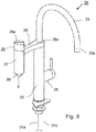
- FIG. 6 a water outlet fitting with an outlet for filtered water is shown, in which a filter cartridge according to the invention can be used as a filter insert.
- the water outlet fitting 20 shown comprises a fitting body 22 which is screwed onto a worktop or a kitchen sink.
- the water outlet 23 serves as an outlet for service water.
- service water is understood to mean hot water, cold water or mixed water, as it is obtained from the public water supply or an in-house water supply, but which has no or questionable drinking water quality.
- the water outlet fitting 20 has two supply lines 24a, 24b for hot water and cold water and a single-lever mixer 25 with a corresponding valve insert, with which the hot and cold water supplied can be mixed and output via the water outlet 23.
- a single-lever mixer 25 with which the hot and cold water supplied can be mixed and output via the water outlet 23.
- water paths thus lead in a manner which is also known per se from the supply lines 24a, 24b to the mixing valve 25 and from there to the water outlet 23.
- a second outlet line 26 branches off, at the end of which a filter housing 27 pointing vertically downwards is arranged.
- the outlet line 26 is designed in the form of an annular shoulder 26a, which lies concentrically around the upwardly pointing outlet line 23 and is pivotable about the central axis of the fitting body 22.
- a waterway for cold water runs on the inside of the fitting body 22 to the shoulder 26a and opens into an annular space formed inside the shoulder 26a, circumferentially open and sealed against the shoulder 26a, via which the water reaches the second outlet 26.
- the filter housing 27 is approximately cylindrical and converges conically towards its bottom 28. In the middle of this conical bottom area 8 there is an opening 28a, from which filtered drinking water can be dispensed.
- a valve 29 with a rotary handle 29a is arranged in the upper region of the filter housing 27. If this valve 29 is opened, so If water flows via the outlet line 26 into an outer ring area 27a of the filter housing 27, penetrates through the filter-active layers 4 of the filter cartridge 1 inserted in the filter housing 27 and is discharged axially via the mouthpiece 6.
- the filter housing 27 is shown enlarged in a longitudinal section.
- the filter cartridge 1 has the mouth piece 6, which is in the form of a downwardly pointing collar around the outlet opening of the axial interior space 5.
- the diameter of the opening 28a in the bottom 28 of the filter housing 27 is dimensioned such that the mouthpiece 6 fits through and is received by the opening 28a. Filtered water thus flows out through the mouthpiece 6 without coming into contact with the filter housing 27.
- the closing valve 29 can be seen with its valve handle 29a and a valve insert 29b located underneath.
- a spindle of the valve insert 29b is actuated and the valve 29 releases the water path coming from the outlet line 26 into the filter housing 27.
- valve insert 29b Between the valve insert 29b and the filter housing 27 there is also a check valve 30 with a closing body 30a, which is held in its open position upward by an actuating pin 31a.
- the confirmation pin 31a in turn is held upward by the filter cartridge 1 inserted into the filter housing 27, so that the check valve 30 is open when the filter cartridge 1 is inserted and the filter housing 27 is screwed on.
- a downwardly pointing receiving base 26b for the filter housing 27 is formed, on which the latter is fastened in a watertight manner by means of a screw or bayonet lock. If the filter housing 27 is removed in order to change the filter insert 1, the valve body 30a is moved downward into its closed position by the water pressure or alternatively a closing spring (not shown here) so that no water can escape from the outlet line 26.
- a battery-operated electrical circuit 33 is integrated into the valve cap 29a, which provides information about the state of the filter insert 1 via a multicolored light-emitting diode 34.
- the circuit 33 only contains a timer which is reset after the filter cartridge 1 has been replaced and which reminds the filter cartridge 1 to replace it after a preset operating time has elapsed.
- a flow meter arranged in the waterway, for example in the form of an impeller meter, so that an exchange of the filter cartridge 1 can be indicated depending on the amount of filtered water.
- the light-emitting diode 34 flashes green (e.g. every 5 seconds). After the intended period of use has expired, i.e. when an exchange of the filter cartridge 1 is recommended, the color of the light-emitting diode 34 changes to red. If the filter cartridge needs to be replaced and the drinking quality of the filter water is no longer guaranteed, the flashing frequency is also increased as a warning, e.g. rapid flashing 1x per second.
- the upper end face of the filter cartridge 1 is closed by its upper housing part 2.
- the confirmation pin 31a is supported on the upper side of the housing part 2 and is held by the latter in its upper position, in which it holds the check valve 30 in the open position.
- the seal 8 on the underside of the filter cartridge 1 seals the outer annular space 27a of the filter housing 27 towards the bottom 28 of the filter housing 27, so that water that has flown in from the outlet line 26 only enters the axial interior 5 of the filter insert after it has penetrated the filter-active layers 4 1 and can flow out from there through the mouth piece 6 attached to the filter insert.
Landscapes
- Chemical & Material Sciences (AREA)
- Engineering & Computer Science (AREA)
- Water Supply & Treatment (AREA)
- Life Sciences & Earth Sciences (AREA)
- Hydrology & Water Resources (AREA)
- Chemical Kinetics & Catalysis (AREA)
- Environmental & Geological Engineering (AREA)
- Organic Chemistry (AREA)
- Nanotechnology (AREA)
- Health & Medical Sciences (AREA)
- Public Health (AREA)
- Water Treatment By Sorption (AREA)
Description
- Die vorliegende Erfindung betrifft einen Filtereinsatz zur Verwendung in einer Wasserauslaufarmatur mit integriertem Trinkwasserfilter, wobei der Filtereinsatz eine allseitig geschlossene Bauform mit einem innenseitigen Hohlraum aufweist und zumindest ein Teil seiner Außenfläche als filteraktive Fläche ausgebildet ist, die von zu filterndem Wasser von außen nach innen durchdrungen wird, und der Filtereinsatz eine Mündungsöffnung aufweist, durch die gefiltertes Wasser aus dem innenseitigen Hohlraum ausströmen kann.
- In vielen Gegenden entspricht die Qualität des Wassers aus der öffentlichen Wasserversorgung oder aus einer hauseigenen Wasserversorgung nicht den Hygieneanforderungen an Trinkwasser. In diesem Fall können Trinkwasserfilter eingesetzt werden, um im Brauchwasser enthaltene Verunreinigungen herauszufiltern. Bekannt sind zu diesem Zweck nachrüstbare Filteraufsätze, die auf die Mündungsöffnung des Wasserauslaufs einer Armatur aufgeschraubt oder aufgesteckt werden und einen entsprechenden Trinkwasserfilter enthalten. Derartige nachrüstbaren Filteraufsätze sind beispielsweise in den Dokumenten
EP 798424 A2 JP 2002/310357 JP 2002/331298 A WO 1999/037375 A1 oderWO 99/29391 A1 - In der
US 2010/0096314 A1 ist ein Filtergehäuse zum Aufschrauben auf einen Wasserauslauf beschrieben. In dem Filtergehäuse ist eine Filterkartusche eingesetzt. Am Auslass der Filterkartusche befindet sich ein Strahlregler, der separat an der Auslassseite des Filtergehäuses eingesetzt ist. Ein ähnlicher Wasserfilter zum Aufschrauben auf einen Wasserauslauf ist in derDE 196 18 692 A1 gezeigt. Auch hier befindet sich am Auslass der Filterkartusche ein Strahlregler, der separat an der Auslassseite des Filtergehäuses eingesetzt ist. - Daneben sind Armaturen bekannt, die einen integrierten Trinkwasserfilter aufweisen. Beispielsweise zeigt die
EP 2 249 942 B1 eine Armatur mit im Armaturenkörper integriertem Filter. Die SchriftUS 2014/0215709 A1 beschreibt eine Armatur mit einem separaten Abgang am Armaturenkörper, auf den eine nach oben weisende Filterkartusche aufgesetzt werden kann, an der ein separater Auslauf für gefiltertes Wasser angebracht wird. Über diese Armatur kann somit wahlweise Brauchwasser und gefiltertes Trinkwasser entnommen werden. - Die in der
WO 2013/044339 A1 beschriebene Armatur besitzt ebenfalls einen im Armaturenkorpus aufgenommenen Filter. Am Armaturenkorpus sind zwei Ausläufe angeordnet, aus denen wahlweise Brauchwasser und gefiltertes Trinkwasser entnommen werden kann. Auch dieWO 2012/029412 A1 zeigt schematisch eine Armatur mit einem Auslauf für Brauchwasser, einen Filter sowie einen von dem Filter abgehenden separaten Auslauf für gefiltertes Wasser. - In der
WO91/10493 - Nachteilig an solchen Armaturen mit integriertem Trinkwasserfilter ist, dass hinter dem Filter jeweils wasserführende Teile der Armatur wie insbesondere Ventile, ein rohrförmiger Auslauf, oder im Armaturenkörper ausgebildete Wasserwege folgen, in denen sich Keime ansiedeln können, die das gefilterte Wasser verunreinigen. Eine solche Keimbildung innerhalb der Armatur kann insbesondere in warmen Gegenden problematisch sein. Gefiltertes Trinkwasser könnte daher hinter dem Filter unbemerkt mit Krankheitskeimen kontaminiert werden.
- Es ist daher eine Aufgabe der vorliegenden Erfindung, einen Filtereinsatz für eine Wasserauslaufarmatur mit integriertem Trinkwasserfilter anzugeben, welcher in Hinblick auf die Hygiene und Sicherheit verbessert ist.
- Die Aufgabe wird gelöst durch die Merkmale des Anspruchs 1. Vorteilhafte Ausgestaltungen sind den abhängigen Ansprüchen zu entnehmen.
- Bei einer Wasserauslaufarmatur der eingangs genannten Art ist erfindungsgemäß vorgesehen, dass an dem Filtereinsatz ein in Form eines Kragens nach außen weisendes Mündungsstück ausgebildet ist, welches von einer Öffnung in einem armaturenseitigen Filtergehäuse aufgenommen werden kann und aus welchem gefiltertes Wasser ohne Kontakt zu dem Filtergehäuse frei ausströmen kann. Gemäß der vorliegenden Erfindung ist somit vorgesehen, dass das gefilterte Trinkwasser direkt aus dem Filtereinsatz ausfließt und entnommen wird, so dass jede Keimbildung in einem daran anschließenden Wasserweg vermieden wird. Durch die geschlossene Bauform, stellt die komplette Außenseite der Filterpatrone, die beispielsweise beim Einsetzen angefasst wird und somit Kontaminationen ausgesetzt ist, die "unreine" Seite des Filtereinsatzes dar, während der Innenraum des Filtereinsatzes dessen reine Seite bildet und somit vor Umwelteinflüssen und Kontamination geschützt ist.
- Außerdem umfasst das Mündungsstück zusätzlich einen integrierten Strahlregler. Ein solcher Strahlregler ist üblicherweise am Auslauf einer Armatur angeordnet und sorgt dafür, dass das Wasser mit der gewünschten Strahlcharakteristik, gegebenenfalls belüftet, aus dem Auslauf austritt. Ein solcher Strahlregler ist konstruktionsbedingt besonders anfällig für die Anlagerung von Verschmutzungen und kann eine Quelle von Keimbildung innerhalb der Armatur darstellen. Indem dieser Strahlregler nun integriert mit der Filterkartusche als Einwegartikel ausgebildet ist, entfällt dieser als Quelle für Keimbildung, ohne auf die mit einem Strahlregler verbundene Komfortfunktion verzichten zu müssen.
- Das am Filtereinsatz angeordnete Mündungsstück kann im Auslieferungszustand außerdem mittels einer Abreißfolie steril versiegelt sein. Diese wird erst entfernt, wenn der Filtereinsatz in das Filtergehäuse eingesetzt wird. Somit ist der hygienisch einwandfreie Zustand des Filtereinsatzes gewährleistet, da die Mündungsöffnung als einzige Verbindungsstelle zwischen der sterilen Innenseite des Filtereinsatzes mit der Umwelt solange der Filtereinsatz nicht in Gebrauch ist, versiegelt ist.
- Bei einer bevorzugten Ausführungsform ist der Filtereinsatz als zylindrische Filterpatrone mit einer Mantelfläche, zwei gegenüberliegenden Stirnflächen und mit einem axialen Innenraum ausgebildet, wobei das Mündungsstück vorzugsweise mittig an einer der Stirnflächen angeordnet ist. Die radialsymmetrische, insbesondere zylindrische Form von Filterpatrone und Filtergehäuse ist bevorzugt, da hierbei die Filterpatrone von außen angeströmt und das gefilterte Wasser direkt aus dem axialen Innenraum des Filters entnommen werden kann. Vorzugsweise ist die dem Mündungsstück abgewandte Stirnfläche der Filterpatrone hingegen wasserdicht verschlossen.
- Die filteraktive Fläche wird im Wesentlichen von der Mantelfläche der zylindrischen Filterpatrone gebildet. Die Stirnflächen sind vorzugsweise als Kunststoffformteile ausgeführt, die über entlang der Mantelfläche in axialer Richtung verlaufenden und in Umfangsrichtung beabstandete Verbindungsstege miteinander verbunden sind. Eine solche Bauform ist kostengünstig und bietet ein stabiles Stützgerüst für den Filtereinsatz. Beispielsweise können die Kunststoffformteile als Spritzgussteile ausgeführt sein. Hierbei ist es insbesondere möglich, die Stirnfläche mit dem Mündungsstück und einem integrierten Strahlregler im selben Spritzgussteil zu integrieren, was die Herstellung erheblich vereinfacht.
- Die Stützstruktur der Filterpatrone kann insbesondere zweiteilig, aus zwei miteinander verbundenen Kunststoffformteilen ausgeführt werden. Die Verbindung dieser Formteile kann lösbar, vorzugsweise mittels einer Schnappverbindung erfolgen, oder unlösbar, beispielsweise durch Verkleben oder durch UltraschallSchweißen.
- Bei einer bevorzugten Bauform des Filtereinsatzes ist die filteraktive Fläche mit einer nanoporösen Polymermembran versehen. Eine solche nanoporöse Membrane weist eine Vielzahl von Poren im Nano-Bereich z.B. mit einer Porenweite von 5 - 400 nm, vorzugsweise 15 - 200 nm, auf. Die Poren in der Membran sorgen für einen ausreichenden Wasserdurchtritt. Im Wasser enthaltene Mikropartikel wie etwa mikrobiologische Verunreinigungen werden jedoch zurückgehalten, so dass das gefilterte Wasser keimfrei ist.
- Eine solche nanoporöse Polymermembran kann hergestellt sein, indem Nanopartikel eines Salzes - also einer anorganischen Verbindung aus einem MetallKation und einem Nichtmetall-Anion - in einer flüssigen Polymerlösung in Suspension gebracht, die Polymerlösung auf ein Substrat zu einer dünnen Membrane ausgestrichen und auspolymerisiert wird und die Salzpartikel anschließend mit einem geeigneten Lösungsmittel - vorzugsweise Wasser - aus der von dem Polymer gebildeten Matrix herausgelöst werden.
- Innenseitig der nanoporösen Polymermembran kann eine zusätzliche Filterlage mit Aktivkohle angeordnet sein. Diese dient als Adsorptionsmittel zur Entfernung etwaiger nach Durchdringen der nanoporösen Membrane im Wasser noch verbliebener Farb-, Geschmacks- und Geruchsstoffe. Insbesondere werden durch die Aktivkohleschicht gelöste Gase wie etwa Chlor und Ozon entfernt und so der Geschmack des gefilterten Wassers erheblich verbessert.
- Alternativ oder kumulativ kann innenseitig der nanoporösen Polymermembran eine zusätzliche Filterlage mit aktiven Silberpartikeln angeordnet sein. Diese sorgt durch die antimikrobakterielle Wirkung feiner Silberpartikel (Nano-Silber) dafür, dass sich im Filter keine Mikroorganismen bilden und diesen von innen heraus verunreinigen können.
- Schließlich kann außenseitig der nanoporösen Polymermembran als Vorfilter eine zusätzliche Filterlage aus Filtervlies angeordnet sein. Durch ein solches Filtervlies werden gröbere Schwebstoffe und Verunreinigungen im Wasser wie etwa Mikroplastik-Teile abgehalten und können sich so nicht auf der nanoporösen Membrane niederschlagen und diese zusetzen.
- Ein Filtereinsatz mit dem genannten Filteraufbau ist kostengünstig in der Herstellung, kann sehr kompakt gebaut werden und ermöglicht dennoch eine hohe Durchflussrate von bis zu 8 l/min bei einem Außendruck von 3 bar. Er ermöglicht eine nahezu 100%-tige Entfernung von Schwebstoffen, Mikroorganismen und Krankheitserregern (> 99%), Rost, Mikroplastik, sowie unangenehmen Geschmacks- und Geruchstoffen.
- Um den Filtereinsatz gegenüber einem armaturenseitigen Filtergehäuse zu dichten kann um das Mündungsstück eine nach außen abstehende, ringförmige Dichtung angebracht sein. Somit wird mit dem Filtereinsatz automatisch auch die Dichtung zwischen Filtereinsatz und Filtergehäuse getauscht, so dass sich keine Undichtigkeiten durch verschlissene Dichtungen ergeben können, durch die ungefiltertes Wasser am Filtereinsatz vorbei zu dessen Mündungsöffnung gelangen und das gefilterte Wasser auf diese Weise verunreinigen könnte.
- Außerdem wird eine Wasserauslaufarmatur mit integriertem Trinkwasserfilter angegeben. Diese weist einen Armaturenkörper mit mindestens einem Wasserzulauf, einen von dem Armaturenkörper abzweigenden Auslauf für gefiltertes Trinkwasser und einen von Wasser durchströmbaren Filteraufnahmeraum für einen Trinkwasserfilter auf, der mit dem Auslauf in wasserführender Verbindung steht. Erfindungsgemäß wird der Filteraufnahmeraum von einem Filtergehäuse gebildet, das an dem von dem Armaturenkörper abgewandten Ende des Auslaufs angeordnet ist. Das Filtergehäuse besitzt einen nach unten weisenden Boden mit einer Öffnung. In das Filtergehäuse ist ein Filtereinsatz der vorstehend beschriebenen Art eingesetzt, dessen nach außen weisendes Mündungsstück von der Öffnung im Boden des Filtergehäuses aufgenommen ist, so dass gefiltertes Wasser ohne Kontakt zu dem Filtergehäuse frei ausströmen kann. Weitere Vorteile und Ausgestaltungen der vorliegenden Erfindung ergeben sich aus der nachfolgenden Beschreibung bevorzugter Ausführungsbeispiele anhand der Figuren. Diese zeigen:
-
Figur 1 eine isometrische Darstellung einer zylindrischen Filterpatrone mit daran angebrachtem Mündungsstück, -
Figur 2 Draufsicht auf die Unterseite der Filterpatrone ausFigur 2 , -
Figur 3 einen Längsschnitt durch die Filterpatrone ausFigur 1 mit zusätzlicher, am Mündungsstück angebrachter Abreißfolie, -
Figur 4 das Detail X ausFigur 3 betreffend die Rastverbindung der Gehäuseteile der Filterpatrone, -
Figur 5 eine schematische Zeichnung des Aufbaus der Filterlagen, die bei einer Filterpatrone wie inFigur 1 zum Einsatz kommen, -
Figur 6 eine isometrische Darstellung einer Wasserauslaufarmatur mit einem separaten Auslauf für gefiltertes Wasser, an dessen Ende ein Filtergehäuse zur Aufnahme einer Filterpatrone angeordnet ist und -
Figur 7 einen Längsschnitt durch das Filtergehäuse der Armatur aus Figur 6. - In den
Figuren 1 bis 3 ist eine zylindrische Filterpatrone 1 dargestellt, die als Filtereinsatz zur Filterung von Trinkwasser in einer Wasserauslaufarmatur eingesetzt wird. Die Stirnflächen der zylindrischen Filterpatrone 1 werden von Gehäuseteilen 2, 3 aus Kunststoff gebildet und die Mantelfläche 4 wirkt als filteraktive Fläche und wird von zu filterndem Wasser von außen nach innen durchdrungen. Das obere Gehäuseteil 2 umfasst die obere Stirnfläche der Filterpatrone 1 und verschließt diese wasserdicht. Von dieser führen Verbindungsstege 2a zu einem unteren Abschlussring 2b. Insgesamt sind vier Verbindungsstege 2a in Umfangsrichtung verteilt angeordnet. An dem Abschlussring 2b ist das untere Gehäuseteil 3, welches die untere Stirnfläche der Filterpatrone 1 bildet, mittels Schnappverbindungen befestigt. - Die Gehäuseteile 2, 3 sind als Kunststoffspritzgussteile ausgeführt und bilden ein stabilisierendes Gerüst für die Filterpatrone 1. Innerhalb dieses Gerüsts sind in mehreren Lagen die filteraktiven Schichten 4 angeordnet. Sie umschließen einen axialen Innenraum 5 (siehe
Figur 3 ), in welchem sich das gefilterte Wasser gelangt. An der Unterseite der Filterpatrone 1 ist an deren unterem Gehäuseteil 3 ein Mündungsstück 6 ausgebildet. Dieses bildet eine Mündungsöffnung, zu der Wasser aus dem axialen Innenraum 5 aus der Filterpatrone 1 ausströmen kann. - In das Mündungsstück 6 ist ein Strahlregler 7 einstückig integriert. Ein Strahlregler ist üblicherweise am Auslauf einer Armatur angeordnet und sorgt dafür, dass das Wasser mit der gewünschten Strahlcharakteristik, gegebenenfalls belüftet, aus dem Auslauf austritt. Ein solcher Strahlregler ist konstruktionsbedingt besonders anfällig für die Anlagerung von Verschmutzungen und kann daher eine Quelle von Keimbildung innerhalb der Armatur darstellen. Indem der Strahlregler nun integriert mit der Filterpatrone 1 als Einwegpartikel ausgebildet ist, entfällt dieser als Quelle für Keimbildung, ohne auf die mit einem Strahlregler verbundene Komfortfunktion verzichten zu müssen.
- An der Unterseite des unteren Gehäuseteils 3 ist außerdem eine Dichtung 8 angebracht. Diese liegt ringförmig mit einigem Abstand um das Mündungsstück 6 und sorgt dafür, dass die Filterpatrone 1, wenn sie in ein armaturenseitiges Filtergehäuse eingesetzt wird, gegenüber dem Boden des Filtergehäuses abgedichtet ist. Im Ausführungsbeispiel ist die Dichtung 8 zweilippig ausgeführt, das heißt sie besitzt zwei nebeneinander angebrachte, nach unten weisende Dichtlippen. Die Dichtung 8 ist in eine nach unten hin offene Nut im Bodenteil 3 der Filterpatrone 1 eingesetzt.
- Die beiden Gehäuseteile 2, 3 der Filterpatrone sind im Ausführungsbeispiel mittels Schnappverbindungen miteinander verrastet. Hierzu sind am unteren Gehäuseteil 3 mehrere in Umfangsrichtung verteilte Schnapphaken 3a angeformt, die in umfangsseitige Aussparungen im unteren Abschlussring 2b des oberen Gehäuseteils 2 eingreifen und dort verrasten. Das in
Figur 4 gezeigte Detail X ausFigur 3 zeigt die Schnappverbindung zwischen oberem und unterem Gehäuseteil in einer vergrößerten Darstellung. Eine solche Schnappverbindung ist besonders kostengünstig und einfach herzustellen. Selbstverständlich sind auch andere Möglichkeiten, die Gehäuseteile 2 und 3 zu verbinden, im Rahmen der vorliegenden Erfindung möglich und von dieser mit umfasst. Beispielsweise können die Gehäuseteile mittels Ultraschallschweißen stoffschlüssig verbunden werden. - In
Figur 3 ist außerdem gezeigt, dass die von dem Mündungsstück 6 gebildete Mündungsöffnung von einer Abreißfolie 9 steril verschlossen ist. Die Abreißfolie 9 kann wie inFigur 3 angedeutet, mittels einer Klebstofffuge 9a aufgebracht sein. Ebenso ist es möglich, die Abreißfolie 9 mit dem Mündungsstück zu verschweißen. Die Abreißfolie 9 verhindert das Eindringen von Keimen und Schmutz während der Lagerung der Patrone. Vor dem Einsetzen der Filterpatrone 1 in ein armaturenseitiges Filtergehäuse wird die Abreißfolie entfernt. Die Patrone 1 ist nun einsatzbereit. - In
Figur 5 ist schematisch der Aufbau der filteraktiven Schichten 4 gezeigt. Die äußerste Filterlage wird von einem Filtervlies 10 gebildet. Dieses wirkt als Vorfilter für gröbere, im Wasser enthaltene Verschmutzungen und Schwebstoffe. Anschließend kommt als nächste Filterlage eine nanoporöse Polymermembran 11. Eine solche Membran ist beispielsweise in der SchriftWO 2012/097967 A1 beschrieben, auf die zur Vermeidung unnötiger Wiederholungen hiermit voll inhaltlich Bezug genommen wird. Sie weist Poren mit einer Porenweite im Bereich zwischen 15 und 200 nm auf. Die Poren in der Membran sorgen für einen ausreichenden Wasserdurchtritt. Im Wasser enthaltene Mikropartikel wie etwa mikrobiologische Verunreinigungen, Bakterien, Viren und dergleichen werden jedoch zurückgehalten, sodass das gefilterte Wasser keimfrei ist. Zuinnerst kommt schließlich eine Filterschicht 12 aus bzw. mit Aktivkohle. Diese sorgt dafür, dass auch im Wasser enthaltene Gase wie Chlor oder Ozon adsorbiert werden und das gefilterte Wasser somit geruchs- und geschmacksneutral ist. Die Filterlage 12 kann zusätzlich aktive Silberpartikel enthalten, die keimtötend wirken und somit dafür sorgen, dass im Inneren des Filters keine Keimbildung stattfinden kann. Die Filterlagen 10, 11, 12 umschließen den axialen Innenraum 5 des Filters, aus dem in axialer Richtung nach unten gefiltertes Wasser durch die von dem Mündungsstück 6 gebildete Mündungsöffnung tritt. - In
Figur 6 ist schließlich eine Wasserauslaufarmatur mit einem Auslauf für gefiltertes Wasser gezeigt, in dem eine erfindungsgemäße Filterpatrone als Filtereinsatz verwendet werden kann. Die inFigur 6 gezeigte Wasserauslaufarmatur 20 umfasst einen Armaturenkörper 22, der auf einer Arbeitsplatte oder einer Küchenspüle verschraubt wird. Nach oben hin erstreckt sich aus dem Armaturenkörper 22 ein gebogener Wasserauflauf 23 mit einem Mündungsstück 23a herkömmlicher Bauart, beispielsweise einem Strahlregler. Der Wasserauslauf 23 dient als Auslauf für Brauchwasser. Als Brauchwasser wird im Rahmen der Erfindung Warmwasser, Kaltwasser oder Mischwasser verstanden, wie es aus der öffentlichen Wasserversorgung oder einer hauseigenen Wasserversorgung bezogen wird, welches aber keine bzw. fragliche Trinkwasserqualität aufweist. - Die Wasserauslaufarmatur 20 hat zwei Zuleitungen 24a, 24b für Warmwasser und Kaltwasser sowie einen Ein-Hebel-Mischer 25 mit entsprechendem Ventileinsatz, mit dem das zugeführte Warm- und Kaltwasser gemischt und über den Wasserauslauf 23 ausgegeben werden kann. Innerhalb des Armaturenkörpers 22 führen somit in an sich ebenfalls bekannter Weise Wasserwege von den Zuleitungen 24a, 24b zum Mischventil 25 und von dort zum Wasserauslauf 23.
- Im oberen Bereich des Armaturenkörpers 22 zweigt eine zweite Auslaufleitung 26 ab, an deren Ende ein senkrecht nach unten weisendes Filtergehäuse 27 angeordnet ist. Im Bereich der Abzweigung ist die Auslaufleitung 26 in Form einer ringförmigen Schulter 26a ausgebildet, die konzentrisch um die nach oben weisende Auslaufleitung 23 liegt und um die Mittelachse des Armaturenkörpers 22 schwenkbar ist. Ein Wasserweg für Kaltwasser verläuft innenseitig des Armaturenkörpers 22 zu der Schulter 26a und mündet dort in einem innerhalb der Schulter 26a ausgebildeten, umfangseitig offenen und gegenüber der Schulter 26a gleitend gedichteten Ringraum, über den das Wasser in den zweiten Auslauf 26 gelangt.
- Das Filtergehäuse 27 ist in etwa zylindrisch ausgebildet und läuft zu seinem Boden 28 hin kegelförmig zusammen. In der Mitte dieses kegelförmigen Bodenbereichs 8 befindet sich eine Öffnung 28a, aus der gefiltertes Trinkwasser ausgegeben werden kann. Hierzu ist im oberen Bereich des Filtergehäuses 27 ein Ventil 29 mit einem Drehgriff 29a angeordnet. Wird dieses Ventil 29 geöffnet, so strömt Wasser über die Auslaufleitung 26 in einen äußeren Ringbereich 27a des Filtergehäuses 27, dringt durch die filteraktiven Lagen 4 der im Filtergehäuse 27 eingesetzten Filterpatrone 1 hindurch und wird axial über das Mündungsstück 6 ausgegeben.
- In
Figur 7 ist das Filtergehäuse 27 vergrößert in einem Längsschnitt dargestellt. Die Filterpatrone 1 weist am unteren Ende das Mündungsstück 6 auf, welches in Form eines nach unten weisenden Kragens um die Austrittsöffnung des axialen Innenraums 5 liegt. Der Durchmesser der Öffnung 28a im Boden 28 des Filtergehäuses 27 ist so bemessen, dass das Mündungsstück 6 hindurch passt und von der Öffnung 28a aufgenommen wird. Gefiltertes Wasser strömt somit durch das Mündungsstück 6 aus, ohne in Kontakt mit dem Filtergehäuse 27 zu gelangen. - Im oberen Bereich des Filtergehäuses 27 ist das Schließventil 29 mit seinem Ventilgriff 29a und einem darunter befindlichen Ventileinsatz 29b zu sehen. Durch Drehen des Ventilgriffs 29a wird eine Spindel des Ventileinsatzes 29b betätigt und das Ventil 29 gibt den Wasserweg von der Auslaufleitung 26 kommend ins Filtergehäuse 27 frei.
- Zwischen dem Ventileinsatz 29b und dem Filtergehäuse 27 befindet sich außerdem ein Rückschlagventil 30 mit einem Schließkörper 30a, der von einem Bestätigungsstift 31a nach oben in seiner geöffneten Stellung gehalten wird. Der Bestätigungsstift 31a wiederum wird von der in das Filtergehäuse 27 eingesetzten Filterpatrone 1 nach oben gehalten, sodass das Rückschlagventil 30 bei eingesetzter Filterpatrone 1 und aufgeschraubtem Filtergehäuse 27 geöffnet ist.
- Am Ende der Wasserauslaufleitung 26 ist ein nach unten weisender Aufnahmesockel 26b für das Filtergehäuse 27 angeformt, an dem dieses mittels eines Schraub- oder Bajonett-Verschlusses wasserdicht befestigt ist. Wird das Filtergehäuse 27 abgenommen, um den Filtereinsatz 1 zu wechseln, so wird durch den Wasserdruck oder alternativ eine (hier nicht gezeigte) Schließfeder der Ventilkörper 30a nach unten in seine Schließstellung bewegt, sodass kein Wasser aus der Auslaufleitung 26 austreten kann.
- Im Betrieb fließt Wasser aus der Auslaufleitung 26 bei geöffnetem Ventil 29 und eingesetzter Filterpatrone 1 in einen äußeren Ringraum 27a des Filtergehäuses 27. Von dort durchströmt es das Filtermaterial 4 der Filterpatrone 1 und gelangt in den axialen Hohlraum 5 der Filterpatrone. Von dort fließt es durch das an der Unterseite der Filterpatrone 1 angeformte Mündungsstück 6, welches durch die Öffnung 28a im Boden 28 des Filtergehäuses 27 hindurch ragt, aus dem Auslass der Armatur 20 heraus, beispielsweise in ein von einem Benutzer darunter platziertes Trinkgefäß.
- Als eine zusätzliche (optionale) Funktion ist in die Ventilkappe 29a eine batteriebetriebene elektrische Schaltung 33 integriert, die über eine mehrfarbige Leuchtdiode 34 Auskunft über den Zustand des Filtereinsatzes 1 gibt. Im Ausführungsbeispiel enthält die Schaltung 33 lediglich einen Timer, der nach Austausch der Filterpatrone 1 zurückgesetzt wird und nach Ablauf einer voreingestellten Betriebszeit für die Filterpatrone 1 an einen Austausch erinnert. Möglich ist jedoch alternativ oder kumulativ auch die Verwendung eines im Wasserweg angeordneten Durchflussmessers, beispielsweise in Form eines Flügelradzählers, so dass ein Austausch der Filterpatrone 1 in Abhängigkeit der gefilterten Wassermenge angezeigt werden kann. Solange die Filterpatrone 1 in innerhalb ihrer vorgesehenen Verwendungsdauer ist, blinkt die Leuchtdiode 34 grün (z.B. alle 5 sec). Nach Ablauf der vorgesehenen Verwendungsdauer, wenn also ein Austausch der Filterpatrone 1 empfohlen wird, wechselt die Farbe der Leuchtdiode 34 auf rot. Ist ein Austausch der Filterpatrone überfällt und die Trinkqualität des Filterwassers somit nicht mehr gewährleistet, so wird als Warnung zusätzlich die Blinkfrequenz erhöht, z.B. schnelles Blinken 1x pro Sekunde.
- Wie bereits erläutert, ist die obere Stirnseite der Filterpatrone 1 durch deren oberes Gehäuseteil 2 verschlossen. Der Bestätigungsstift 31a stützt sich bei eingesetzter Filterpatrone 1 an der Oberseite des Gehäuseteils 2 ab und wird von diesem in seiner oberen Stellung gehalten, in der er das Rückschlagventil 30 in Offenstellung hält. Die Dichtung 8 an der Unterseite der Filterpatrone 1 dichtet den äußeren Ringraum 27a des Filtergehäuses 27 nach unten hin gegen den Boden 28 des Filtergehäuses 27 ab, sodass aus der Auslaufleitung 26 eingeströmtes Wasser lediglich nach Durchdringen der filteraktiven Schichten 4 in den axialen Innenraum 5 des Filtereinsatzes 1 gelangen kann und von dort durch das am Filtereinsatz angebrachte Mündungsstück 6 ausfließen kann.
Claims (12)
- Filtereinsatz (1) zur Verwendung in einer Wasserauslaufarmatur (20) mit integriertem Trinkwasserfilter, wobei der Filtereinsatz (1) eine allseitig geschlossene Bauform mit einem innenseitigen Hohlraum (5) aufweist und zumindest ein Teil seiner Außenfläche (4) als filteraktive Fläche ausgebildet ist, die von zu filterndem Wasser von außen nach innen durchdrungen wird, und der Filtereinsatz (1) eine Mündungsöffnung aufweist, durch die gefiltertes Wasser aus dem innenseitigen Hohlraum (5) ausströmen kann, wobei an dem Filtereinsatz (1) ein in Form eines Kragens nach außen weisendes, die Mündungsöffnung bildendes Mündungsstück (6) ausgebildet ist, welches von einer Öffnung (28a) in einem armaturenseitigen Filtergehäuse (27) aufgenommen werden kann und aus welchem gefiltertes Wasser ohne Kontakt zu dem Filtergehäuse (27) frei ausströmen kann und dass das Mündungsstück (6) einen integrierten Strahlregler (7) aufweist.
- Filtereinsatz nach Anspruch 1, bei der das Mündungsstück (6) im Auslieferungszustand mittels einer Abreißfolie (9) steril versiegelt ist.
- Filtereinsatz nach einem der vorangehenden Ansprüche, welcher als zylindrische Filterpatrone mit einer Mantelfläche, zwei gegenüberliegenden Stirnflächen und mit einem axialen Innenraum ausgebildet ist, wobei das Mündungsstück (6) vorzugsweise mittig an einer der Stirnflächen angeordnet ist.
- Filtereinsatz nach Anspruch 3, bei dem die zweite, dem Mündungsstück (6) abgewandte Stirnfläche der Filterpatrone wasserdicht verschlossen ist.
- Filtereinsatz nach Anspruch 3 oder 4, bei dem die filteraktive Fläche (4) im Wesentlichen von der Mantelfläche gebildet wird und die Stirnflächen als Kunststoffformteile (2, 3) ausgeführt sind, die über entlang der Mantelfläche in axialer Richtung verlaufenden und in Umfangsrichtung beabstandete Verbindungsstege (2a) miteinander verbunden sind.
- Filtereinsatz nach einem der vorangehenden Ansprüche, bei der die filteraktive Fläche (4) mit einer nanoporösen Polymermembran (11) versehen ist.
- Filtereinsatz nach Anspruch 6, bei der die nanoporöse Polymermembran (11) Poren mit einer Porenweite von 5 - 400 nm, vorzugsweise 15 - 200 nm, aufweist.
- Filtereinsatz nach Anspruch 6 oder 7, bei der innenseitig der nanoporösen Polymermembran (11) eine zusätzliche Filterlage mit Aktivkohle (12) angeordnet ist.
- Filtereinsatz nach einem der Ansprüche 6 bis 8, bei der innenseitig der nanoporösen Polymermembran (11) eine zusätzliche Filterlage mit aktiven Silberpartikeln angeordnet ist.
- Filtereinsatz nach einem der Ansprüche 6 bis 9, bei der außenseitig der nanoporösen Polymermembran (11) als Vorfilter eine zusätzliche Filterlage aus Filtervlies (10) angeordnet ist.
- Filtereinsatz nach einem der vorangehenden Ansprüche, bei der um das Mündungsstück (6) eine nach außen abstehende, ringförmige Dichtung (8) angebracht ist.
- Wasserauslaufarmatur (20) zur Abgabe von gefiltertem Trinkwasser, welche
einen Armaturenkörper (22) mit mindestens einem Wasserzulauf (24a, 24b), einen von dem Armaturenkörper (22) abzweigenden Auslauf (26) für gefiltertes Trinkwasser und einen von Wasser durchströmbaren Filteraufnahmeraum für einen Trinkwasserfilter aufweist, der mit dem Auslauf (26) in wasserführender Verbindung steht,
dadurch gekennzeichnet, dass
der Filteraufnahmeraum von einem Filtergehäuse (27) gebildet wird, das an dem von dem Armaturenkörper (22) abgewandten Ende des Auslaufs (26) angeordnet ist, dass das Filtergehäuse (27) einen nach unten weisenden Boden (28) aufweist, in welchem eine Öffnung (28a) ausgebildet ist, dass in den Filteraufnahmeraum ein Filtereinsatz (1) nach einem der vorangehenden Ansprüche eingesetzt ist und dass dessen nach außen weisendes Mündungsstück (6) von der Öffnung (28a) im Boden (28) des Filtergehäuses (27) aufgenommen ist, so dass gefiltertes Wasser ohne Kontakt zu dem Filtergehäuse (27) frei ausströmen kann.
Priority Applications (1)
| Application Number | Priority Date | Filing Date | Title |
|---|---|---|---|
| PL19178127T PL3583992T3 (pl) | 2018-06-18 | 2019-06-04 | Wkład filtra do armatury wypływu wody z filtrem wody pitnej |
Applications Claiming Priority (1)
| Application Number | Priority Date | Filing Date | Title |
|---|---|---|---|
| DE102018114582.9A DE102018114582A1 (de) | 2018-06-18 | 2018-06-18 | Filtereinsatz für eine Wasserauslaufarmatur mit Trinkwasserfilter |
Publications (2)
| Publication Number | Publication Date |
|---|---|
| EP3583992A1 EP3583992A1 (de) | 2019-12-25 |
| EP3583992B1 true EP3583992B1 (de) | 2021-05-19 |
Family
ID=66752006
Family Applications (1)
| Application Number | Title | Priority Date | Filing Date |
|---|---|---|---|
| EP19178127.7A Active EP3583992B1 (de) | 2018-06-18 | 2019-06-04 | Filtereinsatz für eine wasserauslaufarmatur mit trinkwasserfilter |
Country Status (5)
| Country | Link |
|---|---|
| US (1) | US20190382287A1 (de) |
| EP (1) | EP3583992B1 (de) |
| CN (1) | CN211799293U (de) |
| DE (1) | DE102018114582A1 (de) |
| PL (1) | PL3583992T3 (de) |
Families Citing this family (4)
| Publication number | Priority date | Publication date | Assignee | Title |
|---|---|---|---|---|
| USD991426S1 (en) * | 2020-12-24 | 2023-07-04 | Tianjin Yunda Industry and Trade Co., Ltd, Inc. | Filter cartridge |
| USD1035824S1 (en) * | 2021-11-30 | 2024-07-16 | 3Awater Oy | Holder for a water filter |
| USD1072163S1 (en) * | 2022-04-27 | 2025-04-22 | Wuhu TianHao E-commerce CO., LTD. | Fuel water separator |
| USD1065433S1 (en) * | 2023-09-25 | 2025-03-04 | WaterH Inc. | Water filter |
Family Cites Families (16)
| Publication number | Priority date | Publication date | Assignee | Title |
|---|---|---|---|---|
| FR1452754A (fr) * | 1965-07-30 | 1966-04-15 | Brise-jet filtre et aérateur | |
| WO1991010493A1 (en) * | 1990-01-16 | 1991-07-25 | Ametek, Inc.-Plymouth Products Division | Multi-function filter cartridge with flow distribution control |
| US5653868A (en) | 1994-04-06 | 1997-08-05 | Mitsubishi Rayon Company Ltd. | Diverter and water purifier having same |
| DE19618692C2 (de) * | 1996-05-09 | 1998-07-02 | Precision Sieves And Filters L | Filtervorrichtung für Wasser |
| US6096197A (en) | 1997-12-11 | 2000-08-01 | Hughes; Douglass E. | Shower filter for chlorine removal and scale deposit prevention |
| PL348456A1 (en) | 1998-01-21 | 2002-05-20 | Clorox Co | Faucet mounted water filter |
| US6251274B1 (en) * | 1999-03-16 | 2001-06-26 | Envirogard Products Limited | Faucet attachment for treating water |
| JP2002310357A (ja) | 2001-04-18 | 2002-10-23 | Toray Ind Inc | 自在継手および浄水器 |
| JP3906344B2 (ja) | 2001-05-09 | 2007-04-18 | 和歌山県 | 排水処理装置および排水処理方法 |
| BE1019019A3 (nl) | 2008-01-14 | 2012-01-10 | Jonghe Marc De | Een watervoorzieningseenheid voor het afleveren van gezuiverd water. |
| US7964099B2 (en) * | 2008-10-22 | 2011-06-21 | Te-Hsing Wang | Water filtering device |
| JP2012050904A (ja) | 2010-08-31 | 2012-03-15 | Panasonic Electric Works Co Ltd | 浄水カートリッジ、当該浄水カートリッジを備えた浄水装置および当該浄水装置を備えた流し台 |
| EP2476724A1 (de) | 2011-01-17 | 2012-07-18 | ETH Zurich | Poröse Polymermembrane |
| BRPI1104487B1 (pt) | 2011-09-26 | 2020-12-01 | Duratex S.A | torneira misturadora com filtro |
| US9650767B2 (en) | 2013-02-01 | 2017-05-16 | Scott Anthony Nightlinger | Sink faucet assembly |
| CN204182216U (zh) * | 2014-11-06 | 2015-03-04 | 陈建光 | 一种家用水龙头净水器 |
-
2018
- 2018-06-18 DE DE102018114582.9A patent/DE102018114582A1/de not_active Ceased
-
2019
- 2019-06-04 EP EP19178127.7A patent/EP3583992B1/de active Active
- 2019-06-04 PL PL19178127T patent/PL3583992T3/pl unknown
- 2019-06-14 US US16/441,468 patent/US20190382287A1/en not_active Abandoned
- 2019-06-17 CN CN201920912408.4U patent/CN211799293U/zh active Active
Also Published As
| Publication number | Publication date |
|---|---|
| EP3583992A1 (de) | 2019-12-25 |
| CN211799293U (zh) | 2020-10-30 |
| US20190382287A1 (en) | 2019-12-19 |
| PL3583992T3 (pl) | 2021-10-18 |
| DE102018114582A1 (de) | 2019-12-19 |
Similar Documents
| Publication | Publication Date | Title |
|---|---|---|
| DE2640115C2 (de) | Vorrichtung zur Wasserreinigung | |
| DE69107023T2 (de) | Reiniger für Leitungswasser. | |
| EP0018527B1 (de) | Rückspülbare Filtereinrichtung, insbesondere für eine Hauswasseranlage | |
| EP3583992A1 (de) | Filtereinsatz für eine wasserauslaufarmatur mit trinkwasserfilter | |
| DE69624118T2 (de) | Dialysemaschine | |
| DE112010003584B4 (de) | Notfall-waschsystem | |
| DE3112037C2 (de) | ||
| EP0253132A1 (de) | Filter zum Reinigen von Leitungswasser | |
| EP2108002A2 (de) | Wasserfiltervorrichtung mit stellorgan zur einstellung eines verschnittverhältnisses | |
| EP3583993B1 (de) | Wasserauslaufarmatur mit trinkwasserfilter | |
| DE202015106890U1 (de) | Rückspülfilter | |
| EP0341345B1 (de) | Ventil mit eingebautem Filtereinsatz | |
| EP2214837B1 (de) | Belüfungsanordnung für brausestrahlen | |
| DE10335343A1 (de) | Keramisches Filterelement zur Reinigung von Wasser | |
| DE2546881A1 (de) | Wasserfiltervorrichtung | |
| DE19648405A1 (de) | Anschlußeinheit für Großgeräte-Wasserfilter | |
| EP1576307B1 (de) | Sanitäre auslaufarmatur | |
| DE8916178U1 (de) | Wasseraustrittsarmatur | |
| DE102012107243B3 (de) | Sanitäres Wasserventil mit einem eine antibakterielle Beschichtung aufweisenden Auslaufteil | |
| DE19615102A1 (de) | Wasserreinigungsvorrichtung | |
| EP0668951A1 (de) | Siebanordnung zur erzeugung eines perlenden wasserstrahles | |
| DE202019005570U1 (de) | Flüssigkeitsreinigungsvorrichtung | |
| EP0284641B1 (de) | Vorrichtung zur Aufnahme und zum Trennen von insbesondere in Zahnarztpraxen anfallenden und im Bohrschlamm od.dgl. enthaltenen Schadstoffen aus Metallverbindungen enthaltenden Zahnfüllmaterialien | |
| DE102009042143A1 (de) | Filteranordnung zur Verwendung in einem Druckregler für eine landwirtschaftliche Austragvorrichtung | |
| WO2023213606A1 (de) | Gekapselte multistufen-filterpatrone für trinkwasserbereitstellungs-vorrichtung und zugehörige trinkwasserbereitstellungs-vorrichtung |
Legal Events
| Date | Code | Title | Description |
|---|---|---|---|
| PUAI | Public reference made under article 153(3) epc to a published international application that has entered the european phase |
Free format text: ORIGINAL CODE: 0009012 |
|
| STAA | Information on the status of an ep patent application or granted ep patent |
Free format text: STATUS: THE APPLICATION HAS BEEN PUBLISHED |
|
| AK | Designated contracting states |
Kind code of ref document: A1 Designated state(s): AL AT BE BG CH CY CZ DE DK EE ES FI FR GB GR HR HU IE IS IT LI LT LU LV MC MK MT NL NO PL PT RO RS SE SI SK SM TR |
|
| AX | Request for extension of the european patent |
Extension state: BA ME |
|
| STAA | Information on the status of an ep patent application or granted ep patent |
Free format text: STATUS: REQUEST FOR EXAMINATION WAS MADE |
|
| 17P | Request for examination filed |
Effective date: 20200512 |
|
| RBV | Designated contracting states (corrected) |
Designated state(s): AL AT BE BG CH CY CZ DE DK EE ES FI FR GB GR HR HU IE IS IT LI LT LU LV MC MK MT NL NO PL PT RO RS SE SI SK SM TR |
|
| GRAP | Despatch of communication of intention to grant a patent |
Free format text: ORIGINAL CODE: EPIDOSNIGR1 |
|
| STAA | Information on the status of an ep patent application or granted ep patent |
Free format text: STATUS: GRANT OF PATENT IS INTENDED |
|
| RIC1 | Information provided on ipc code assigned before grant |
Ipc: E03C 1/08 20060101ALI20201214BHEP Ipc: B01D 35/04 20060101AFI20201214BHEP |
|
| INTG | Intention to grant announced |
Effective date: 20210114 |
|
| RIN1 | Information on inventor provided before grant (corrected) |
Inventor name: LEUTWILER, MARKUS Inventor name: LOEPFE, MICHAEL Inventor name: KELLENBERGER, CHRISTOPH Inventor name: RUEEGG, ANDREAS |
|
| GRAS | Grant fee paid |
Free format text: ORIGINAL CODE: EPIDOSNIGR3 |
|
| GRAA | (expected) grant |
Free format text: ORIGINAL CODE: 0009210 |
|
| STAA | Information on the status of an ep patent application or granted ep patent |
Free format text: STATUS: THE PATENT HAS BEEN GRANTED |
|
| AK | Designated contracting states |
Kind code of ref document: B1 Designated state(s): AL AT BE BG CH CY CZ DE DK EE ES FI FR GB GR HR HU IE IS IT LI LT LU LV MC MK MT NL NO PL PT RO RS SE SI SK SM TR |
|
| REG | Reference to a national code |
Ref country code: GB Ref legal event code: FG4D Free format text: NOT ENGLISH |
|
| REG | Reference to a national code |
Ref country code: CH Ref legal event code: EP |
|
| REG | Reference to a national code |
Ref country code: DE Ref legal event code: R096 Ref document number: 502019001441 Country of ref document: DE |
|
| REG | Reference to a national code |
Ref country code: AT Ref legal event code: REF Ref document number: 1393442 Country of ref document: AT Kind code of ref document: T Effective date: 20210615 |
|
| REG | Reference to a national code |
Ref country code: IE Ref legal event code: FG4D Free format text: LANGUAGE OF EP DOCUMENT: GERMAN |
|
| REG | Reference to a national code |
Ref country code: GR Ref legal event code: EP Ref document number: 20210401523 Country of ref document: GR Effective date: 20210709 |
|
| REG | Reference to a national code |
Ref country code: LT Ref legal event code: MG9D |
|
| REG | Reference to a national code |
Ref country code: NL Ref legal event code: MP Effective date: 20210519 |
|
| PG25 | Lapsed in a contracting state [announced via postgrant information from national office to epo] |
Ref country code: FI Free format text: LAPSE BECAUSE OF FAILURE TO SUBMIT A TRANSLATION OF THE DESCRIPTION OR TO PAY THE FEE WITHIN THE PRESCRIBED TIME-LIMIT Effective date: 20210519 Ref country code: HR Free format text: LAPSE BECAUSE OF FAILURE TO SUBMIT A TRANSLATION OF THE DESCRIPTION OR TO PAY THE FEE WITHIN THE PRESCRIBED TIME-LIMIT Effective date: 20210519 Ref country code: LT Free format text: LAPSE BECAUSE OF FAILURE TO SUBMIT A TRANSLATION OF THE DESCRIPTION OR TO PAY THE FEE WITHIN THE PRESCRIBED TIME-LIMIT Effective date: 20210519 Ref country code: BG Free format text: LAPSE BECAUSE OF FAILURE TO SUBMIT A TRANSLATION OF THE DESCRIPTION OR TO PAY THE FEE WITHIN THE PRESCRIBED TIME-LIMIT Effective date: 20210819 |
|
| PG25 | Lapsed in a contracting state [announced via postgrant information from national office to epo] |
Ref country code: LV Free format text: LAPSE BECAUSE OF FAILURE TO SUBMIT A TRANSLATION OF THE DESCRIPTION OR TO PAY THE FEE WITHIN THE PRESCRIBED TIME-LIMIT Effective date: 20210519 Ref country code: NO Free format text: LAPSE BECAUSE OF FAILURE TO SUBMIT A TRANSLATION OF THE DESCRIPTION OR TO PAY THE FEE WITHIN THE PRESCRIBED TIME-LIMIT Effective date: 20210819 Ref country code: RS Free format text: LAPSE BECAUSE OF FAILURE TO SUBMIT A TRANSLATION OF THE DESCRIPTION OR TO PAY THE FEE WITHIN THE PRESCRIBED TIME-LIMIT Effective date: 20210519 Ref country code: SE Free format text: LAPSE BECAUSE OF FAILURE TO SUBMIT A TRANSLATION OF THE DESCRIPTION OR TO PAY THE FEE WITHIN THE PRESCRIBED TIME-LIMIT Effective date: 20210519 Ref country code: PT Free format text: LAPSE BECAUSE OF FAILURE TO SUBMIT A TRANSLATION OF THE DESCRIPTION OR TO PAY THE FEE WITHIN THE PRESCRIBED TIME-LIMIT Effective date: 20210920 Ref country code: IS Free format text: LAPSE BECAUSE OF FAILURE TO SUBMIT A TRANSLATION OF THE DESCRIPTION OR TO PAY THE FEE WITHIN THE PRESCRIBED TIME-LIMIT Effective date: 20210919 |
|
| PG25 | Lapsed in a contracting state [announced via postgrant information from national office to epo] |
Ref country code: NL Free format text: LAPSE BECAUSE OF FAILURE TO SUBMIT A TRANSLATION OF THE DESCRIPTION OR TO PAY THE FEE WITHIN THE PRESCRIBED TIME-LIMIT Effective date: 20210519 |
|
| PG25 | Lapsed in a contracting state [announced via postgrant information from national office to epo] |
Ref country code: EE Free format text: LAPSE BECAUSE OF FAILURE TO SUBMIT A TRANSLATION OF THE DESCRIPTION OR TO PAY THE FEE WITHIN THE PRESCRIBED TIME-LIMIT Effective date: 20210519 Ref country code: ES Free format text: LAPSE BECAUSE OF FAILURE TO SUBMIT A TRANSLATION OF THE DESCRIPTION OR TO PAY THE FEE WITHIN THE PRESCRIBED TIME-LIMIT Effective date: 20210519 Ref country code: SK Free format text: LAPSE BECAUSE OF FAILURE TO SUBMIT A TRANSLATION OF THE DESCRIPTION OR TO PAY THE FEE WITHIN THE PRESCRIBED TIME-LIMIT Effective date: 20210519 Ref country code: SM Free format text: LAPSE BECAUSE OF FAILURE TO SUBMIT A TRANSLATION OF THE DESCRIPTION OR TO PAY THE FEE WITHIN THE PRESCRIBED TIME-LIMIT Effective date: 20210519 Ref country code: RO Free format text: LAPSE BECAUSE OF FAILURE TO SUBMIT A TRANSLATION OF THE DESCRIPTION OR TO PAY THE FEE WITHIN THE PRESCRIBED TIME-LIMIT Effective date: 20210519 Ref country code: DK Free format text: LAPSE BECAUSE OF FAILURE TO SUBMIT A TRANSLATION OF THE DESCRIPTION OR TO PAY THE FEE WITHIN THE PRESCRIBED TIME-LIMIT Effective date: 20210519 Ref country code: CZ Free format text: LAPSE BECAUSE OF FAILURE TO SUBMIT A TRANSLATION OF THE DESCRIPTION OR TO PAY THE FEE WITHIN THE PRESCRIBED TIME-LIMIT Effective date: 20210519 |
|
| REG | Reference to a national code |
Ref country code: DE Ref legal event code: R097 Ref document number: 502019001441 Country of ref document: DE |
|
| REG | Reference to a national code |
Ref country code: BE Ref legal event code: MM Effective date: 20210630 |
|
| PLBE | No opposition filed within time limit |
Free format text: ORIGINAL CODE: 0009261 |
|
| STAA | Information on the status of an ep patent application or granted ep patent |
Free format text: STATUS: NO OPPOSITION FILED WITHIN TIME LIMIT |
|
| PG25 | Lapsed in a contracting state [announced via postgrant information from national office to epo] |
Ref country code: MC Free format text: LAPSE BECAUSE OF FAILURE TO SUBMIT A TRANSLATION OF THE DESCRIPTION OR TO PAY THE FEE WITHIN THE PRESCRIBED TIME-LIMIT Effective date: 20210519 Ref country code: LU Free format text: LAPSE BECAUSE OF NON-PAYMENT OF DUE FEES Effective date: 20210604 |
|
| 26N | No opposition filed |
Effective date: 20220222 |
|
| PG25 | Lapsed in a contracting state [announced via postgrant information from national office to epo] |
Ref country code: IE Free format text: LAPSE BECAUSE OF NON-PAYMENT OF DUE FEES Effective date: 20210604 |
|
| PG25 | Lapsed in a contracting state [announced via postgrant information from national office to epo] |
Ref country code: IS Free format text: LAPSE BECAUSE OF FAILURE TO SUBMIT A TRANSLATION OF THE DESCRIPTION OR TO PAY THE FEE WITHIN THE PRESCRIBED TIME-LIMIT Effective date: 20210919 Ref country code: FR Free format text: LAPSE BECAUSE OF NON-PAYMENT OF DUE FEES Effective date: 20210719 Ref country code: AL Free format text: LAPSE BECAUSE OF FAILURE TO SUBMIT A TRANSLATION OF THE DESCRIPTION OR TO PAY THE FEE WITHIN THE PRESCRIBED TIME-LIMIT Effective date: 20210519 |
|
| PG25 | Lapsed in a contracting state [announced via postgrant information from national office to epo] |
Ref country code: BE Free format text: LAPSE BECAUSE OF NON-PAYMENT OF DUE FEES Effective date: 20210630 |
|
| PG25 | Lapsed in a contracting state [announced via postgrant information from national office to epo] |
Ref country code: CY Free format text: LAPSE BECAUSE OF FAILURE TO SUBMIT A TRANSLATION OF THE DESCRIPTION OR TO PAY THE FEE WITHIN THE PRESCRIBED TIME-LIMIT Effective date: 20210519 |
|
| P01 | Opt-out of the competence of the unified patent court (upc) registered |
Effective date: 20230602 |
|
| PG25 | Lapsed in a contracting state [announced via postgrant information from national office to epo] |
Ref country code: HU Free format text: LAPSE BECAUSE OF FAILURE TO SUBMIT A TRANSLATION OF THE DESCRIPTION OR TO PAY THE FEE WITHIN THE PRESCRIBED TIME-LIMIT; INVALID AB INITIO Effective date: 20190604 |
|
| PG25 | Lapsed in a contracting state [announced via postgrant information from national office to epo] |
Ref country code: MK Free format text: LAPSE BECAUSE OF FAILURE TO SUBMIT A TRANSLATION OF THE DESCRIPTION OR TO PAY THE FEE WITHIN THE PRESCRIBED TIME-LIMIT Effective date: 20210519 |
|
| PG25 | Lapsed in a contracting state [announced via postgrant information from national office to epo] |
Ref country code: MT Free format text: LAPSE BECAUSE OF FAILURE TO SUBMIT A TRANSLATION OF THE DESCRIPTION OR TO PAY THE FEE WITHIN THE PRESCRIBED TIME-LIMIT Effective date: 20210519 |
|
| PGFP | Annual fee paid to national office [announced via postgrant information from national office to epo] |
Ref country code: PL Payment date: 20250527 Year of fee payment: 7 Ref country code: DE Payment date: 20250604 Year of fee payment: 7 |
|
| PGFP | Annual fee paid to national office [announced via postgrant information from national office to epo] |
Ref country code: GB Payment date: 20250620 Year of fee payment: 7 |
|
| PGFP | Annual fee paid to national office [announced via postgrant information from national office to epo] |
Ref country code: GR Payment date: 20250616 Year of fee payment: 7 |
|
| PGFP | Annual fee paid to national office [announced via postgrant information from national office to epo] |
Ref country code: AT Payment date: 20250616 Year of fee payment: 7 |
|
| PGFP | Annual fee paid to national office [announced via postgrant information from national office to epo] |
Ref country code: IT Payment date: 20250630 Year of fee payment: 7 |
|
| PGFP | Annual fee paid to national office [announced via postgrant information from national office to epo] |
Ref country code: CH Payment date: 20250701 Year of fee payment: 7 |
|
| PG25 | Lapsed in a contracting state [announced via postgrant information from national office to epo] |
Ref country code: TR Free format text: LAPSE BECAUSE OF FAILURE TO SUBMIT A TRANSLATION OF THE DESCRIPTION OR TO PAY THE FEE WITHIN THE PRESCRIBED TIME-LIMIT Effective date: 20210519 |