EP3584024A1 - Lame de scie - Google Patents
Lame de scie Download PDFInfo
- Publication number
- EP3584024A1 EP3584024A1 EP18178426.5A EP18178426A EP3584024A1 EP 3584024 A1 EP3584024 A1 EP 3584024A1 EP 18178426 A EP18178426 A EP 18178426A EP 3584024 A1 EP3584024 A1 EP 3584024A1
- Authority
- EP
- European Patent Office
- Prior art keywords
- grooves
- cutting portion
- grinding
- saw blade
- parallel
- Prior art date
- Legal status (The legal status is an assumption and is not a legal conclusion. Google has not performed a legal analysis and makes no representation as to the accuracy of the status listed.)
- Granted
Links
Images


Classifications
-
- B—PERFORMING OPERATIONS; TRANSPORTING
- B23—MACHINE TOOLS; METAL-WORKING NOT OTHERWISE PROVIDED FOR
- B23D—PLANING; SLOTTING; SHEARING; BROACHING; SAWING; FILING; SCRAPING; LIKE OPERATIONS FOR WORKING METAL BY REMOVING MATERIAL, NOT OTHERWISE PROVIDED FOR
- B23D61/00—Tools for sawing machines or sawing devices; Clamping devices for these tools
- B23D61/006—Oscillating saw blades
-
- B—PERFORMING OPERATIONS; TRANSPORTING
- B23—MACHINE TOOLS; METAL-WORKING NOT OTHERWISE PROVIDED FOR
- B23D—PLANING; SLOTTING; SHEARING; BROACHING; SAWING; FILING; SCRAPING; LIKE OPERATIONS FOR WORKING METAL BY REMOVING MATERIAL, NOT OTHERWISE PROVIDED FOR
- B23D61/00—Tools for sawing machines or sawing devices; Clamping devices for these tools
- B23D61/12—Straight saw blades; Strap saw blades
- B23D61/121—Types of set; Variable teeth, e.g. variable in height or gullet depth; Varying pitch; Details of gullet
- B23D61/1212—Varying pitch
-
- B—PERFORMING OPERATIONS; TRANSPORTING
- B23—MACHINE TOOLS; METAL-WORKING NOT OTHERWISE PROVIDED FOR
- B23D—PLANING; SLOTTING; SHEARING; BROACHING; SAWING; FILING; SCRAPING; LIKE OPERATIONS FOR WORKING METAL BY REMOVING MATERIAL, NOT OTHERWISE PROVIDED FOR
- B23D61/00—Tools for sawing machines or sawing devices; Clamping devices for these tools
- B23D61/12—Straight saw blades; Strap saw blades
- B23D61/127—Straight saw blades; Strap saw blades of special material
-
- B—PERFORMING OPERATIONS; TRANSPORTING
- B23—MACHINE TOOLS; METAL-WORKING NOT OTHERWISE PROVIDED FOR
- B23D—PLANING; SLOTTING; SHEARING; BROACHING; SAWING; FILING; SCRAPING; LIKE OPERATIONS FOR WORKING METAL BY REMOVING MATERIAL, NOT OTHERWISE PROVIDED FOR
- B23D61/00—Tools for sawing machines or sawing devices; Clamping devices for these tools
- B23D61/12—Straight saw blades; Strap saw blades
- B23D61/128—Sabre saw blades
-
- B—PERFORMING OPERATIONS; TRANSPORTING
- B23—MACHINE TOOLS; METAL-WORKING NOT OTHERWISE PROVIDED FOR
- B23D—PLANING; SLOTTING; SHEARING; BROACHING; SAWING; FILING; SCRAPING; LIKE OPERATIONS FOR WORKING METAL BY REMOVING MATERIAL, NOT OTHERWISE PROVIDED FOR
- B23D65/00—Making tools for sawing machines or sawing devices for use in cutting any kind of material
-
- B—PERFORMING OPERATIONS; TRANSPORTING
- B23—MACHINE TOOLS; METAL-WORKING NOT OTHERWISE PROVIDED FOR
- B23D—PLANING; SLOTTING; SHEARING; BROACHING; SAWING; FILING; SCRAPING; LIKE OPERATIONS FOR WORKING METAL BY REMOVING MATERIAL, NOT OTHERWISE PROVIDED FOR
- B23D65/00—Making tools for sawing machines or sawing devices for use in cutting any kind of material
- B23D65/02—Making saw teeth by punching, cutting, or planing
Definitions
- the invention relates to a saw blade comprising a body of hard material with the features of the preamble of claim 1 and a method to produce a saw blade with the features of the preamble of claim 13.
- the object of the present invention is to provide saw blade comprising a body of hard material and a method to produce a saw blade in which these drawbacks are overcome.
- Hard material is understood to be a material chosen from the group consisting of hard metal, high speed steel and/or ceramic.
- Hard metal is understood to be a composite material comprising cemented carbide (mostly tungsten carbide, WC) with a metal binder phase (usually Cobalt, Co).
- a saw blade with the features of claim 1 and a method to produce a saw blade with the features of claim 13.
- Preferred embodiments of the invention are defined in the dependent claims.
- a preferred use of a saw blade according to the invention is for cutting wood, soft metals (such as aluminum or magnesium) or plastics.
- the invention provides a tooth geometry with excellent cutting performance and at the same time good manufacturability.
- the invention provides
- first direction and the second direction are inclined to each other such that along the length of the cutting portion at least some of the grooves of the first plurality of grooves are intersected by a groove of the second plurality of grooves.
- the inventive arrangement of grooves results in an improvement of the shape of the teeth.
- the first plurality of grooves being "intersected" by a groove of the second type of groove means that the second plurality of grooves crosses and thereby cuts into at least a part of the first plurality of grooves. Thereby, the appearance of a part or all of the grooves of the first plurality of grooves is altered.
- the characteristic of the groove / tooth geometry of the saw blade results from the superimposition of the first plurality of grooves and the second plurality of grooves.
- the second plurality of groove may modify a groove base of the first plurality of grooves, or their flanks, or both.
- the second plurality of grooves may have the same groove shape and size as the first type of grooves (of the first plurality of grooves). It can be foreseen, however, that the second type of grooves differs from the first in terms of shape and / or size.
- the resulting tooth shape provides an even distribution of cutting forces onto the individual cutting teeth. Also beneficial is the good chip evacuation with the inventive tooth design, the teeth shape resulting from the arrangement of the grooves.
- the first direction and the second direction are inclined to a direction that is parallel to the width of the cutting portion and are inclined to a direction that is parallel to the length of the cutting portion.
- one of the first direction and the second direction is parallel to the width of the cutting portion.
- one type of grooves is parallel to the width of the cutting portion.
- one type of grooves is essentially perpendicular to an oscillating / reciprocating movement of the saw blade.
- grooves of the first plurality of grooves which are intersected by grooves of the second plurality of grooves are alternated with grooves of the first plurality of grooves which are not intersected by a groove of the second plurality of grooves.
- not all of the grooves of the first plurality of grooves are crossed by the second type of grooves.
- Grooves of the first type can be followed by the second type directly, that is in an "A-B-A-B-A-B etc.” order, or the sequence may be different, for example an "A-A-B-A-A-B-A-A-B etc.” order, "A” and "B” thereby denoting grooves of the first or the second type.
- the orientation of the second plurality of grooves is chosen such that one groove of the second plurality of grooves crosses two or more grooves of the first type of grooves. It can be understood that the resulting grooves differ from each other as the second groove crosses at different lateral position of the grooves of the first plurality of grooves. Thus, more than two groove characteristics can be realized.
- an angle between the first direction and the second direction lies in a range of about 1° to about 90°, preferably in a range of about 5° to about 45°, especially preferred in a range of about 10° to about 30°. It has been shown that within the above angle ranges especially balanced cutting properties of the saw blade can be achieved.
- a distance between grooves of the second plurality of grooves is larger than a distance between grooves of the first plurality of grooves, preferably the distance between grooves of the second plurality of grooves is double the distance between grooves of the first plurality of grooves.
- the number of the first groove type would be double the number of the second type.
- a cross section of each of the grooves of the first plurality of grooves which are not intersected by a groove of the second plurality of grooves is basically V-shaped.
- the (initial) groove shape follows the shape of the grinding wheel.
- all the grooves of the plurality of grooves are equally shaped.
- the grooves of the second type (of the second plurality of grooves) have the same initial shape, e.g. described as cross section, as the grooves of the first plurality of grooves. Obviously, its initial shape is not necessarily directly visible at the saw blade - as it is superimposed with the other groove type - but it still can be determined by analysis of the final groove shape.
- the cross section of the grooves of the second type (of the second plurality of grooves) have a different initial or imaginary shape to the shape of grooves of the first plurality of grooves.
- the shape of the grooves of the second type may be a more acute V-shape than the V-shape of the first type of grooves.
- the cross-section of the body of hard material widens into a direction of the cutting teeth tips.
- the cross-section of the body may be of trapezoidal shape. The effect of this preferred shape is that the saw blade has a side clearance in its feed direction. This leads to reduced friction during operation of a saw blade equipped with said body of hard metal.
- the present preferred embodiment thus provides a side clearance solution for hard and brittle materials.
- the grooves or teeth could be realized by electroerosion or direct pressing. However, grinding is preferred.
- lateral sides (flanks) of adjacent teeth which together form a groove are either both faceted (consist each of at least two angled partial plane surfaces) or are both formed by a single plane surface.
- the saw blade according to the invention has an aggressive tooth design and cuts very effectively. As compared to conventional full-steel saw blades, the inventive saw blades show increased service life and improved edge retention.
- the saw blade can be in the form of an oscillating or reciprocating saw blade, such as an oscillating blade saw, a jig saw, or a saber saw.
- the invention provides a very cost-effective way to manufacture saw blades comprising a body of a hard material, in particular saw blades comprising a body of hard metal.
- the inventive method to produce a saw blade is done by grinding a surface of a body of hard material to form a plurality of teeth, the surface having a length and a width.
- the method uses at least one grinding tool having a plurality of spaced grinding surfaces which are parallel to each other along a grinding direction.
- the grinding tool is applied to the surface in a first grinding direction that is preferably inclined to a direction which is parallel to the width of the surface.
- a grinding tool having a plurality of spaced grinding surfaces which are parallel to each other along a grinding direction is applied to the surface in a second grinding direction that is preferably inclined to the direction which is parallel to the width of the surface and is inclined to the first grinding direction.
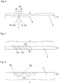
- Fig. 1 shows a cutting portion 3 of a saw blade 1 (cf. Fig. 5 ) having a width W. Only part of the length L is shown.
- a body 2 of hard material a first plurality of grooves 4 running parallel to direction d 1 has been ground and a second plurality of grooves 5 running parallel to direction d 2 has been ground.
- Both directions, d 1 and d 2 are inclined with respect to each other and with respect to a direction dw that is parallel to the width W of the cutting portion 3 and with respect to a direction d L that is parallel to the length L of the cutting portion 3.
- Teeth of the cutting portion 3 are being formed as flanks of the grooves 4, 5. It can be seen that in this embodiment lateral sides of adjacent teeth which together form a groove 4, 5 are either both faceted or are both formed by a single plane surface.
- the first direction d 1 and the second direction d 2 are chosen such that along the length L of the cutting portion 3, teeth of a first type result which are truncated on one of their lateral sides and teeth of a second type result, which alternate with teeth of the first type and which are truncated on the other of their lateral sides, the lateral sides being adjacent to an imaginary longitudinal edge of the cutting portion 3 running along the length L of the cutting portion 3, and such that all teeth are of asymmetrical shape in a direction d L that is parallel to the length L of the cutting portion 3.
- An advantage of such an arrangement lies in the fact that the cutting process is being shared between the teeth of the first and the second type in that, in one direction of the cutting process only the first or second type teeth are engaging the material to be cut and in the other direction of the cutting process the other one of the first or second type teeth are engaging the material to be cut, provided there is a reciprocating motion of the cutting portion 3 along its length L.
- Another advantage lies in the fact that chip removal is facilitated.
- two grooves 4 of the first plurality of grooves 4 which are separated from each by a single groove 5 of the second plurality of grooves 5 are intersected by this single groove 5 of the second plurality of grooves 5, one in a region near the one portion of the cutting portion 3 and the other in a region near the other portion of the cutting portion 3, both regions being separated from each other by a little less than the width W of the cutting portion 3.
- the resulting groove / tooth characteristic provides for aggressive cutting performance and thus high feed rates.
- the directions d 1 and d 2 are both chosen at large angles. It has been found that the resulting groove / tooth characteristic shows low friction. This leads to reduced power consumption and reduced frictional heat.
- Fig. 4 similar to the embodiment of Fig. 1 , only every second groove 4 of the first plurality of grooves 4 is intersected by a groove 5 of the second plurality of grooves 5. It can be seen that in this embodiment lateral sides of adjacent teeth which together form a groove 4, 5 are either both faceted or are both formed by a single plane surface. The embodiment represents a robust tooth geometry with good lifetime.
- Fig. 5 shows part of an inventive saw blade having a cutting portion 3 which is formed on a body 2 of hard material, the body 2 of hard material being welded to a carrier 6 made of steel.
- Fig. 5 there are shown, in exemplary manner also applicable to the other embodiments, the feed direction F and the oscillation direction O.
- the saw blade oscillates or reciprocates along the oscillation direction O.
- the displacements are very small, typically in the range of a few millimeters, while in case of reciprocating saws the displacements measure several millimeters.
- the saw blade moves through a workpiece in feed direction F at a certain feed rate.
- Fig. 6 the different directions that occur with respect to the invention are being shown with respect to a schematic depiction of the cutting portion 3.
- the cutting portion is shown in a top view, that is, parallel and opposite to a later feed direction.
- Fig. 7 shows the result of a first and a second step of a method to produce a saw blade, in particular a saw blade according to at least one of discussed embodiments, by grinding a surface of a body 2 of hard material to form a plurality of teeth, the surface having a length L and a width W, the method using a grinding tool having a plurality of spaced grinding surfaces which are parallel to each other along a grinding direction d g . If a saw blade made of a body 2 of hard material affixed to a carrier 6 is being used, the grinding can take place after the body 2 of hard material has been affixed to the carrier 6.
- the grinding tool is applied to the surface in a first grinding direction d g1 that is inclined to a direction d W which is parallel to the width W of the surface.
- a first subset of the first plurality of equidistant, parallel grooves 4 is being ground, the grooves 4 having a distance 2*G 1 from each other.
- the grinding tool is being offset with respect to the surface along the length L of the surface, the offset corresponding to half of a distance between the spaced grinding surfaces of the grinding tool, that is half tooth pitch.
- a second subset of the first plurality of equidistant, parallel grooves 4 is being ground, the grooves 4 having a distance G 1 from each other.
- the situation shown in Fig. 7 arises (however, not all of the grooves 4 ground along the length L are being shown).
- the offset can be chosen other than half the distance between the spaced grinding surfaces of the grinding tool, that is, other than half tooth pitch, resulting unequally spaced grooves 4 respectively teeth.
- a third step ( Fig. 8 ) the grinding tool is inclined to be parallel to a second grinding direction d g2 that is inclined to the direction d W which is parallel to the width W of the surface and is inclined to the first grinding direction d g1 .
- Fig. 8 not all of the grooves 4, 5 which are ground along the length L are being shown.
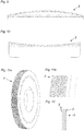
- Fig. 9 shows an embodiment of an inventive saw blade with a convexly curved cutting portion 3.
- Fig. 10 shows an embodiment of an inventive saw blade with a concavely curved cutting portion 3.
- Fig. 11a and 11b show an example for a grinding tool 7 which can be used in a method according to the invention with a plurality of grinding surfaces.
- the grinding surfaces are parallel to each other and are equally spaced along an axis of the grinding tool 7.
- Fig. 12 shows a cross-section of an inventive saw blade 1 in the region of the cutting portion 3 (the individual grooves 4, 5 and teeth which are of course present in the body 2 of hard material are not shown). It can be seen that in this embodiment the cross-section of the body 2 of hard material widens into a direction of the teeth, thus creating a side clearance with the saw blade 1.
Landscapes
- Engineering & Computer Science (AREA)
- Mechanical Engineering (AREA)
- Sawing (AREA)
- Processing Of Stones Or Stones Resemblance Materials (AREA)
- Mechanical Treatment Of Semiconductor (AREA)
- Heat Treatment Of Articles (AREA)
Priority Applications (6)
| Application Number | Priority Date | Filing Date | Title |
|---|---|---|---|
| ES18178426T ES2919926T3 (es) | 2018-06-19 | 2018-06-19 | Hoja de sierra y su método de producción |
| PL18178426.5T PL3584024T3 (pl) | 2018-06-19 | 2018-06-19 | Brzeszczot piły |
| EP18178426.5A EP3584024B1 (fr) | 2018-06-19 | 2018-06-19 | Lame de scie et son procédé de fabrication |
| PCT/EP2019/060906 WO2019242918A1 (fr) | 2018-06-19 | 2019-04-29 | Lame de scie |
| CN201980041000.7A CN112292224A (zh) | 2018-06-19 | 2019-04-29 | 锯片 |
| US17/254,404 US11883893B2 (en) | 2018-06-19 | 2019-04-29 | Saw blade |
Applications Claiming Priority (1)
| Application Number | Priority Date | Filing Date | Title |
|---|---|---|---|
| EP18178426.5A EP3584024B1 (fr) | 2018-06-19 | 2018-06-19 | Lame de scie et son procédé de fabrication |
Publications (2)
| Publication Number | Publication Date |
|---|---|
| EP3584024A1 true EP3584024A1 (fr) | 2019-12-25 |
| EP3584024B1 EP3584024B1 (fr) | 2022-05-04 |
Family
ID=62712827
Family Applications (1)
| Application Number | Title | Priority Date | Filing Date |
|---|---|---|---|
| EP18178426.5A Active EP3584024B1 (fr) | 2018-06-19 | 2018-06-19 | Lame de scie et son procédé de fabrication |
Country Status (6)
| Country | Link |
|---|---|
| US (1) | US11883893B2 (fr) |
| EP (1) | EP3584024B1 (fr) |
| CN (1) | CN112292224A (fr) |
| ES (1) | ES2919926T3 (fr) |
| PL (1) | PL3584024T3 (fr) |
| WO (1) | WO2019242918A1 (fr) |
Cited By (4)
| Publication number | Priority date | Publication date | Assignee | Title |
|---|---|---|---|---|
| DE102021212711A1 (de) | 2021-11-11 | 2023-05-11 | Robert Bosch Gesellschaft mit beschränkter Haftung | Schneidleistenvorrichtung, Sägewerkzeug mit einer solchen Schneidleistenvorrichtung und Verfahren zur Herstellung einer solchen Schneidleistenvorrichtung |
| WO2025083229A1 (fr) * | 2023-10-20 | 2025-04-24 | Robert Bosch Gmbh | Dispositif de coupe et outil d'oscillation |
| DE102024203059A1 (de) * | 2024-04-03 | 2025-10-09 | Robert Bosch Gesellschaft mit beschränkter Haftung | Verfahren zur Herstellung einer Sägevorrichtung sowie Sägevorrichtung und Sägeblatt |
| DE102024203169A1 (de) * | 2024-04-08 | 2025-10-09 | Robert Bosch Gesellschaft mit beschränkter Haftung | Werkzeugvorrichtung und Verfahren zur Herstellung einer solchen |
Families Citing this family (1)
| Publication number | Priority date | Publication date | Assignee | Title |
|---|---|---|---|---|
| DE102024207903A1 (de) | 2024-08-20 | 2026-02-26 | Robert Bosch Gesellschaft mit beschränkter Haftung | Sägeblatt und oszillierendes Multifunktionswerkzeug mit einem solchen Sägeblatt |
Citations (6)
| Publication number | Priority date | Publication date | Assignee | Title |
|---|---|---|---|---|
| US4015331A (en) * | 1975-02-15 | 1977-04-05 | Karl Heinz Balke | Domestic or tradesman's knife |
| JPH06155401A (ja) * | 1992-11-19 | 1994-06-03 | Kiso Power Tool:Kk | 動力鋸 |
| US5855157A (en) * | 1994-02-23 | 1999-01-05 | Matsushita Electric Works, Ltd. | Saw blade |
| DE10303915A1 (de) * | 2003-01-31 | 2004-08-12 | Pi Patent Interconsulting Gmbh | Verfahren zum Ausbilden der Zähne bei der Herstellung einer Säge |
| ES2383627T3 (es) * | 2007-08-20 | 2012-06-22 | Robert Bosch Gmbh | Hoja de sierra de punta |
| US20140157607A1 (en) * | 2012-12-03 | 2014-06-12 | David B. McFarland | Disposable plastic knives with serrated cutting edge |
Family Cites Families (38)
| Publication number | Priority date | Publication date | Assignee | Title |
|---|---|---|---|---|
| US391843A (en) * | 1888-10-30 | William | ||
| US211259A (en) * | 1879-01-07 | Improvement in planing-saws | ||
| US229772A (en) * | 1880-07-06 | Chablouis suisse | ||
| US108040A (en) * | 1870-10-04 | Improvement in saws | ||
| US211346A (en) * | 1879-01-14 | Improvement in saws | ||
| US775012A (en) * | 1904-01-18 | 1904-11-15 | John H Mclean | Saw-teeth. |
| US886296A (en) * | 1907-04-26 | 1908-04-28 | George M Howatson | Crosscut-saw. |
| US1566880A (en) * | 1923-02-08 | 1925-12-22 | Simonds Saw & Steel Co | Saw |
| US1690803A (en) * | 1923-05-10 | 1928-11-06 | Wee George R Vander | Saw |
| US1523518A (en) * | 1923-10-18 | 1925-01-20 | Dragon Louis | Saw |
| US1771722A (en) * | 1929-06-15 | 1930-07-29 | Rudolph B Prentice | Saw |
| US2252869A (en) * | 1937-04-28 | 1941-08-19 | Millers Falls Co | Hacksaw blade |
| US2351737A (en) * | 1940-05-09 | 1944-06-20 | Arthur N Blum | Saw |
| FI27347A (fi) * | 1952-09-25 | 1954-11-10 | Owen J L Person H A | Sågblad |
| SE333079B (fr) * | 1969-03-18 | 1971-03-01 | Oestbergs Fabriks Ab | |
| AT309495B (de) * | 1970-01-09 | 1973-08-27 | Boehler & Co Ag Geb | Kettensägenstahl |
| JPS526194A (en) * | 1975-07-03 | 1977-01-18 | Takeshi Hara | Automatic saw setting device |
| SE419101B (sv) * | 1976-12-17 | 1981-07-13 | Uddeholms Ab | Berarmaterial for verktyg av bimetall der det arbetande materialet utgores av snabbstal |
| SE411722B (sv) * | 1978-01-12 | 1980-02-04 | Sandvik Ab | Skerverktyg |
| US4265285A (en) * | 1980-03-18 | 1981-05-05 | Sandvik, Inc. | Combination cross and rip cut handsaw |
| DE3445206A1 (de) * | 1984-12-12 | 1986-06-12 | Philipp Persch Nachf. Inh. Fritz Henn, 6580 Idar-Oberstein | Diamant-trennscheibe |
| US5361665A (en) * | 1990-09-06 | 1994-11-08 | Sandvik Ab | Saw blade |
| JPH04122601A (ja) * | 1990-09-13 | 1992-04-23 | Yoichi Kajiwara | 鋸 |
| US5423845A (en) * | 1991-03-07 | 1995-06-13 | Biomet, Inc. | Surgical saw blade |
| JPH081605A (ja) * | 1994-06-22 | 1996-01-09 | Mamoru Kobayashi | 手引き鋸 |
| TW269653B (en) * | 1994-08-19 | 1996-02-01 | Black & Decker Inc | Saw blade tooth form and method therefor |
| US5687484A (en) * | 1996-03-25 | 1997-11-18 | Hahn; Michael | Pumpkin carving knife |
| US5848473A (en) * | 1997-01-29 | 1998-12-15 | Fiskars Inc. | Saw blade |
| DE19712448C2 (de) * | 1997-03-08 | 2000-07-27 | Diamik Diamant Werkzeuge Gmbh | Stammblatt für ein rotierendes Bearbeitungswerkzeug |
| EP1034871A3 (fr) * | 1999-03-11 | 2002-10-02 | Kapman AB | Lame de scie à ruban à dents avoyées et à forces latérales réduites |
| US6681674B2 (en) * | 2001-02-23 | 2004-01-27 | William Hakansson | Band saw blade |
| SE526794C2 (sv) * | 2004-03-11 | 2005-11-08 | Kapman Ab | Sågblad för trä |
| JP5173670B2 (ja) * | 2008-08-20 | 2013-04-03 | 株式会社アマダ | 鋸刃及びその製造方法 |
| JP2013052575A (ja) * | 2011-09-02 | 2013-03-21 | Kishimoto Nokogu Seisakusho:Kk | 鋸刃 |
| KR101790501B1 (ko) * | 2014-06-04 | 2017-10-26 | 가부시키가이샤 유에무 고교 | 손톱 |
| USD745351S1 (en) * | 2014-10-15 | 2015-12-15 | Frito-Lay North America, Inc. | Blade |
| KR102339435B1 (ko) * | 2015-08-26 | 2021-12-14 | 가부시키가이샤 유에무 고교 | 손톱 |
| AT16111U1 (de) * | 2017-11-15 | 2019-01-15 | Ceratizit Luxembourg S A R L | Schneidwerkzeug |
-
2018
- 2018-06-19 ES ES18178426T patent/ES2919926T3/es active Active
- 2018-06-19 PL PL18178426.5T patent/PL3584024T3/pl unknown
- 2018-06-19 EP EP18178426.5A patent/EP3584024B1/fr active Active
-
2019
- 2019-04-29 WO PCT/EP2019/060906 patent/WO2019242918A1/fr not_active Ceased
- 2019-04-29 CN CN201980041000.7A patent/CN112292224A/zh active Pending
- 2019-04-29 US US17/254,404 patent/US11883893B2/en active Active
Patent Citations (6)
| Publication number | Priority date | Publication date | Assignee | Title |
|---|---|---|---|---|
| US4015331A (en) * | 1975-02-15 | 1977-04-05 | Karl Heinz Balke | Domestic or tradesman's knife |
| JPH06155401A (ja) * | 1992-11-19 | 1994-06-03 | Kiso Power Tool:Kk | 動力鋸 |
| US5855157A (en) * | 1994-02-23 | 1999-01-05 | Matsushita Electric Works, Ltd. | Saw blade |
| DE10303915A1 (de) * | 2003-01-31 | 2004-08-12 | Pi Patent Interconsulting Gmbh | Verfahren zum Ausbilden der Zähne bei der Herstellung einer Säge |
| ES2383627T3 (es) * | 2007-08-20 | 2012-06-22 | Robert Bosch Gmbh | Hoja de sierra de punta |
| US20140157607A1 (en) * | 2012-12-03 | 2014-06-12 | David B. McFarland | Disposable plastic knives with serrated cutting edge |
Cited By (4)
| Publication number | Priority date | Publication date | Assignee | Title |
|---|---|---|---|---|
| DE102021212711A1 (de) | 2021-11-11 | 2023-05-11 | Robert Bosch Gesellschaft mit beschränkter Haftung | Schneidleistenvorrichtung, Sägewerkzeug mit einer solchen Schneidleistenvorrichtung und Verfahren zur Herstellung einer solchen Schneidleistenvorrichtung |
| WO2025083229A1 (fr) * | 2023-10-20 | 2025-04-24 | Robert Bosch Gmbh | Dispositif de coupe et outil d'oscillation |
| DE102024203059A1 (de) * | 2024-04-03 | 2025-10-09 | Robert Bosch Gesellschaft mit beschränkter Haftung | Verfahren zur Herstellung einer Sägevorrichtung sowie Sägevorrichtung und Sägeblatt |
| DE102024203169A1 (de) * | 2024-04-08 | 2025-10-09 | Robert Bosch Gesellschaft mit beschränkter Haftung | Werkzeugvorrichtung und Verfahren zur Herstellung einer solchen |
Also Published As
| Publication number | Publication date |
|---|---|
| PL3584024T3 (pl) | 2022-08-22 |
| US20210129243A1 (en) | 2021-05-06 |
| EP3584024B1 (fr) | 2022-05-04 |
| CN112292224A (zh) | 2021-01-29 |
| US11883893B2 (en) | 2024-01-30 |
| WO2019242918A1 (fr) | 2019-12-26 |
| ES2919926T3 (es) | 2022-07-29 |
Similar Documents
| Publication | Publication Date | Title |
|---|---|---|
| US11883893B2 (en) | Saw blade | |
| US5884547A (en) | Saw blade tooth form | |
| US10926343B2 (en) | Ground set saw blade | |
| US4727788A (en) | Saw blade | |
| EP0958088B1 (fr) | Structure de dent de lame de scie a ruban | |
| CN1073916C (zh) | 有刀架和刀头的刀具 | |
| US10279408B2 (en) | Ground set saw blade | |
| US6257226B1 (en) | Metal-cutting saw having straight and set teeth and method of making | |
| CN1678436A (zh) | 切割刃带有凹槽的切割工具 | |
| JP5584046B2 (ja) | 帯鋸刃の製造方法 | |
| US5901630A (en) | Band saw blade or hacksaw with double formation of cutting elements | |
| JPH06155158A (ja) | のこ刃 | |
| US20090126205A1 (en) | Saw Blade With Round Cutting Edges | |
| JP2002505626A (ja) | 改良された帯鋸 | |
| CN104918739A (zh) | 具有不同材料齿的锯片及制造方法 | |
| JP6726853B2 (ja) | チップセパレータ歯を備える帯鋸 | |
| KR20100012443A (ko) | 비철금속절단용 원형커터 | |
| US12290869B2 (en) | Tipped saw blade | |
| US20060118341A1 (en) | Drill in particular masonry drill | |
| JP4420464B2 (ja) | チップソー | |
| EP1053815A2 (fr) | Lame de scie à groupes de dents récurrents à hauteurs et largeurs différentes pour obtenir une coupe lisse | |
| JP3187689U (ja) | 丸鋸刃 | |
| JP5592093B2 (ja) | 鋸刃 | |
| JPH0516059U (ja) | 鋸 刃 | |
| JP3206035U (ja) | チップソー |
Legal Events
| Date | Code | Title | Description |
|---|---|---|---|
| PUAI | Public reference made under article 153(3) epc to a published international application that has entered the european phase |
Free format text: ORIGINAL CODE: 0009012 |
|
| STAA | Information on the status of an ep patent application or granted ep patent |
Free format text: STATUS: THE APPLICATION HAS BEEN PUBLISHED |
|
| AK | Designated contracting states |
Kind code of ref document: A1 Designated state(s): AL AT BE BG CH CY CZ DE DK EE ES FI FR GB GR HR HU IE IS IT LI LT LU LV MC MK MT NL NO PL PT RO RS SE SI SK SM TR |
|
| AX | Request for extension of the european patent |
Extension state: BA ME |
|
| STAA | Information on the status of an ep patent application or granted ep patent |
Free format text: STATUS: REQUEST FOR EXAMINATION WAS MADE |
|
| 17P | Request for examination filed |
Effective date: 20200522 |
|
| RBV | Designated contracting states (corrected) |
Designated state(s): AL AT BE BG CH CY CZ DE DK EE ES FI FR GB GR HR HU IE IS IT LI LT LU LV MC MK MT NL NO PL PT RO RS SE SI SK SM TR |
|
| STAA | Information on the status of an ep patent application or granted ep patent |
Free format text: STATUS: EXAMINATION IS IN PROGRESS |
|
| 17Q | First examination report despatched |
Effective date: 20210407 |
|
| GRAP | Despatch of communication of intention to grant a patent |
Free format text: ORIGINAL CODE: EPIDOSNIGR1 |
|
| STAA | Information on the status of an ep patent application or granted ep patent |
Free format text: STATUS: GRANT OF PATENT IS INTENDED |
|
| INTG | Intention to grant announced |
Effective date: 20211208 |
|
| GRAS | Grant fee paid |
Free format text: ORIGINAL CODE: EPIDOSNIGR3 |
|
| GRAA | (expected) grant |
Free format text: ORIGINAL CODE: 0009210 |
|
| STAA | Information on the status of an ep patent application or granted ep patent |
Free format text: STATUS: THE PATENT HAS BEEN GRANTED |
|
| AK | Designated contracting states |
Kind code of ref document: B1 Designated state(s): AL AT BE BG CH CY CZ DE DK EE ES FI FR GB GR HR HU IE IS IT LI LT LU LV MC MK MT NL NO PL PT RO RS SE SI SK SM TR |
|
| REG | Reference to a national code |
Ref country code: GB Ref legal event code: FG4D |
|
| REG | Reference to a national code |
Ref country code: CH Ref legal event code: EP |
|
| REG | Reference to a national code |
Ref country code: AT Ref legal event code: REF Ref document number: 1488488 Country of ref document: AT Kind code of ref document: T Effective date: 20220515 |
|
| REG | Reference to a national code |
Ref country code: DE Ref legal event code: R096 Ref document number: 602018034798 Country of ref document: DE |
|
| REG | Reference to a national code |
Ref country code: IE Ref legal event code: FG4D |
|
| REG | Reference to a national code |
Ref country code: NL Ref legal event code: FP |
|
| REG | Reference to a national code |
Ref country code: SE Ref legal event code: TRGR |
|
| REG | Reference to a national code |
Ref country code: ES Ref legal event code: FG2A Ref document number: 2919926 Country of ref document: ES Kind code of ref document: T3 Effective date: 20220729 |
|
| REG | Reference to a national code |
Ref country code: LT Ref legal event code: MG9D |
|
| REG | Reference to a national code |
Ref country code: AT Ref legal event code: MK05 Ref document number: 1488488 Country of ref document: AT Kind code of ref document: T Effective date: 20220504 |
|
| PG25 | Lapsed in a contracting state [announced via postgrant information from national office to epo] |
Ref country code: PT Free format text: LAPSE BECAUSE OF FAILURE TO SUBMIT A TRANSLATION OF THE DESCRIPTION OR TO PAY THE FEE WITHIN THE PRESCRIBED TIME-LIMIT Effective date: 20220905 Ref country code: NO Free format text: LAPSE BECAUSE OF FAILURE TO SUBMIT A TRANSLATION OF THE DESCRIPTION OR TO PAY THE FEE WITHIN THE PRESCRIBED TIME-LIMIT Effective date: 20220804 Ref country code: LT Free format text: LAPSE BECAUSE OF FAILURE TO SUBMIT A TRANSLATION OF THE DESCRIPTION OR TO PAY THE FEE WITHIN THE PRESCRIBED TIME-LIMIT Effective date: 20220504 Ref country code: HR Free format text: LAPSE BECAUSE OF FAILURE TO SUBMIT A TRANSLATION OF THE DESCRIPTION OR TO PAY THE FEE WITHIN THE PRESCRIBED TIME-LIMIT Effective date: 20220504 Ref country code: GR Free format text: LAPSE BECAUSE OF FAILURE TO SUBMIT A TRANSLATION OF THE DESCRIPTION OR TO PAY THE FEE WITHIN THE PRESCRIBED TIME-LIMIT Effective date: 20220805 Ref country code: FI Free format text: LAPSE BECAUSE OF FAILURE TO SUBMIT A TRANSLATION OF THE DESCRIPTION OR TO PAY THE FEE WITHIN THE PRESCRIBED TIME-LIMIT Effective date: 20220504 Ref country code: BG Free format text: LAPSE BECAUSE OF FAILURE TO SUBMIT A TRANSLATION OF THE DESCRIPTION OR TO PAY THE FEE WITHIN THE PRESCRIBED TIME-LIMIT Effective date: 20220804 Ref country code: AT Free format text: LAPSE BECAUSE OF FAILURE TO SUBMIT A TRANSLATION OF THE DESCRIPTION OR TO PAY THE FEE WITHIN THE PRESCRIBED TIME-LIMIT Effective date: 20220504 |
|
| PG25 | Lapsed in a contracting state [announced via postgrant information from national office to epo] |
Ref country code: RS Free format text: LAPSE BECAUSE OF FAILURE TO SUBMIT A TRANSLATION OF THE DESCRIPTION OR TO PAY THE FEE WITHIN THE PRESCRIBED TIME-LIMIT Effective date: 20220504 Ref country code: LV Free format text: LAPSE BECAUSE OF FAILURE TO SUBMIT A TRANSLATION OF THE DESCRIPTION OR TO PAY THE FEE WITHIN THE PRESCRIBED TIME-LIMIT Effective date: 20220504 Ref country code: IS Free format text: LAPSE BECAUSE OF FAILURE TO SUBMIT A TRANSLATION OF THE DESCRIPTION OR TO PAY THE FEE WITHIN THE PRESCRIBED TIME-LIMIT Effective date: 20220904 |
|
| PG25 | Lapsed in a contracting state [announced via postgrant information from national office to epo] |
Ref country code: SM Free format text: LAPSE BECAUSE OF FAILURE TO SUBMIT A TRANSLATION OF THE DESCRIPTION OR TO PAY THE FEE WITHIN THE PRESCRIBED TIME-LIMIT Effective date: 20220504 Ref country code: SK Free format text: LAPSE BECAUSE OF FAILURE TO SUBMIT A TRANSLATION OF THE DESCRIPTION OR TO PAY THE FEE WITHIN THE PRESCRIBED TIME-LIMIT Effective date: 20220504 Ref country code: RO Free format text: LAPSE BECAUSE OF FAILURE TO SUBMIT A TRANSLATION OF THE DESCRIPTION OR TO PAY THE FEE WITHIN THE PRESCRIBED TIME-LIMIT Effective date: 20220504 Ref country code: EE Free format text: LAPSE BECAUSE OF FAILURE TO SUBMIT A TRANSLATION OF THE DESCRIPTION OR TO PAY THE FEE WITHIN THE PRESCRIBED TIME-LIMIT Effective date: 20220504 Ref country code: DK Free format text: LAPSE BECAUSE OF FAILURE TO SUBMIT A TRANSLATION OF THE DESCRIPTION OR TO PAY THE FEE WITHIN THE PRESCRIBED TIME-LIMIT Effective date: 20220504 |
|
| REG | Reference to a national code |
Ref country code: DE Ref legal event code: R097 Ref document number: 602018034798 Country of ref document: DE |
|
| REG | Reference to a national code |
Ref country code: BE Ref legal event code: MM Effective date: 20220630 |
|
| PG25 | Lapsed in a contracting state [announced via postgrant information from national office to epo] |
Ref country code: MC Free format text: LAPSE BECAUSE OF FAILURE TO SUBMIT A TRANSLATION OF THE DESCRIPTION OR TO PAY THE FEE WITHIN THE PRESCRIBED TIME-LIMIT Effective date: 20220504 |
|
| PLBE | No opposition filed within time limit |
Free format text: ORIGINAL CODE: 0009261 |
|
| STAA | Information on the status of an ep patent application or granted ep patent |
Free format text: STATUS: NO OPPOSITION FILED WITHIN TIME LIMIT |
|
| PG25 | Lapsed in a contracting state [announced via postgrant information from national office to epo] |
Ref country code: AL Free format text: LAPSE BECAUSE OF FAILURE TO SUBMIT A TRANSLATION OF THE DESCRIPTION OR TO PAY THE FEE WITHIN THE PRESCRIBED TIME-LIMIT Effective date: 20220504 |
|
| 26N | No opposition filed |
Effective date: 20230207 |
|
| PG25 | Lapsed in a contracting state [announced via postgrant information from national office to epo] |
Ref country code: LU Free format text: LAPSE BECAUSE OF NON-PAYMENT OF DUE FEES Effective date: 20220619 Ref country code: IE Free format text: LAPSE BECAUSE OF NON-PAYMENT OF DUE FEES Effective date: 20220619 |
|
| PG25 | Lapsed in a contracting state [announced via postgrant information from national office to epo] |
Ref country code: SI Free format text: LAPSE BECAUSE OF FAILURE TO SUBMIT A TRANSLATION OF THE DESCRIPTION OR TO PAY THE FEE WITHIN THE PRESCRIBED TIME-LIMIT Effective date: 20220504 Ref country code: BE Free format text: LAPSE BECAUSE OF NON-PAYMENT OF DUE FEES Effective date: 20220630 |
|
| PG25 | Lapsed in a contracting state [announced via postgrant information from national office to epo] |
Ref country code: MK Free format text: LAPSE BECAUSE OF FAILURE TO SUBMIT A TRANSLATION OF THE DESCRIPTION OR TO PAY THE FEE WITHIN THE PRESCRIBED TIME-LIMIT Effective date: 20220504 Ref country code: CY Free format text: LAPSE BECAUSE OF FAILURE TO SUBMIT A TRANSLATION OF THE DESCRIPTION OR TO PAY THE FEE WITHIN THE PRESCRIBED TIME-LIMIT Effective date: 20220504 |
|
| PG25 | Lapsed in a contracting state [announced via postgrant information from national office to epo] |
Ref country code: HU Free format text: LAPSE BECAUSE OF FAILURE TO SUBMIT A TRANSLATION OF THE DESCRIPTION OR TO PAY THE FEE WITHIN THE PRESCRIBED TIME-LIMIT; INVALID AB INITIO Effective date: 20180619 |
|
| PG25 | Lapsed in a contracting state [announced via postgrant information from national office to epo] |
Ref country code: MT Free format text: LAPSE BECAUSE OF FAILURE TO SUBMIT A TRANSLATION OF THE DESCRIPTION OR TO PAY THE FEE WITHIN THE PRESCRIBED TIME-LIMIT Effective date: 20220504 |
|
| PG25 | Lapsed in a contracting state [announced via postgrant information from national office to epo] |
Ref country code: BG Free format text: LAPSE BECAUSE OF FAILURE TO SUBMIT A TRANSLATION OF THE DESCRIPTION OR TO PAY THE FEE WITHIN THE PRESCRIBED TIME-LIMIT Effective date: 20220504 |
|
| PG25 | Lapsed in a contracting state [announced via postgrant information from national office to epo] |
Ref country code: BG Free format text: LAPSE BECAUSE OF FAILURE TO SUBMIT A TRANSLATION OF THE DESCRIPTION OR TO PAY THE FEE WITHIN THE PRESCRIBED TIME-LIMIT Effective date: 20220504 |
|
| PGFP | Annual fee paid to national office [announced via postgrant information from national office to epo] |
Ref country code: PL Payment date: 20250606 Year of fee payment: 8 Ref country code: DE Payment date: 20250618 Year of fee payment: 8 |
|
| PGFP | Annual fee paid to national office [announced via postgrant information from national office to epo] |
Ref country code: GB Payment date: 20250618 Year of fee payment: 8 |
|
| PGFP | Annual fee paid to national office [announced via postgrant information from national office to epo] |
Ref country code: NL Payment date: 20250618 Year of fee payment: 8 |
|
| PGFP | Annual fee paid to national office [announced via postgrant information from national office to epo] |
Ref country code: FR Payment date: 20250626 Year of fee payment: 8 |
|
| PGFP | Annual fee paid to national office [announced via postgrant information from national office to epo] |
Ref country code: TR Payment date: 20250611 Year of fee payment: 8 |
|
| PGFP | Annual fee paid to national office [announced via postgrant information from national office to epo] |
Ref country code: CZ Payment date: 20250610 Year of fee payment: 8 |
|
| PGFP | Annual fee paid to national office [announced via postgrant information from national office to epo] |
Ref country code: SE Payment date: 20250618 Year of fee payment: 8 |
|
| PGFP | Annual fee paid to national office [announced via postgrant information from national office to epo] |
Ref country code: ES Payment date: 20250728 Year of fee payment: 8 |
|
| PGFP | Annual fee paid to national office [announced via postgrant information from national office to epo] |
Ref country code: IT Payment date: 20250624 Year of fee payment: 8 |
|
| PGFP | Annual fee paid to national office [announced via postgrant information from national office to epo] |
Ref country code: CH Payment date: 20250701 Year of fee payment: 8 |