EP3584041A1 - Procédé de raccordement de composants - Google Patents
Procédé de raccordement de composants Download PDFInfo
- Publication number
- EP3584041A1 EP3584041A1 EP19000294.9A EP19000294A EP3584041A1 EP 3584041 A1 EP3584041 A1 EP 3584041A1 EP 19000294 A EP19000294 A EP 19000294A EP 3584041 A1 EP3584041 A1 EP 3584041A1
- Authority
- EP
- European Patent Office
- Prior art keywords
- marking
- components
- industrial robot
- image recognition
- recognition system
- Prior art date
- Legal status (The legal status is an assumption and is not a legal conclusion. Google has not performed a legal analysis and makes no representation as to the accuracy of the status listed.)
- Withdrawn
Links
Images


Classifications
-
- B—PERFORMING OPERATIONS; TRANSPORTING
- B25—HAND TOOLS; PORTABLE POWER-DRIVEN TOOLS; MANIPULATORS
- B25J—MANIPULATORS; CHAMBERS PROVIDED WITH MANIPULATION DEVICES
- B25J9/00—Program-controlled manipulators
- B25J9/16—Program controls
- B25J9/1679—Program controls characterised by the tasks executed
- B25J9/1687—Assembly, peg and hole, palletising, straight line, weaving pattern movement
-
- B—PERFORMING OPERATIONS; TRANSPORTING
- B25—HAND TOOLS; PORTABLE POWER-DRIVEN TOOLS; MANIPULATORS
- B25J—MANIPULATORS; CHAMBERS PROVIDED WITH MANIPULATION DEVICES
- B25J9/00—Program-controlled manipulators
- B25J9/16—Program controls
- B25J9/1694—Program controls characterised by use of sensors other than normal servo-feedback from position, speed or acceleration sensors, perception control, multi-sensor controlled systems, sensor fusion
- B25J9/1697—Vision controlled systems
-
- G—PHYSICS
- G05—CONTROLLING; REGULATING
- G05B—CONTROL OR REGULATING SYSTEMS IN GENERAL; FUNCTIONAL ELEMENTS OF SUCH SYSTEMS; MONITORING OR TESTING ARRANGEMENTS FOR SUCH SYSTEMS OR ELEMENTS
- G05B2219/00—Program-control systems
- G05B2219/30—Nc systems
- G05B2219/37—Measurements
- G05B2219/37067—Calibrate work surface, reference markings on object, work surface
-
- G—PHYSICS
- G05—CONTROLLING; REGULATING
- G05B—CONTROL OR REGULATING SYSTEMS IN GENERAL; FUNCTIONAL ELEMENTS OF SUCH SYSTEMS; MONITORING OR TESTING ARRANGEMENTS FOR SUCH SYSTEMS OR ELEMENTS
- G05B2219/00—Program-control systems
- G05B2219/30—Nc systems
- G05B2219/37—Measurements
- G05B2219/37097—Marker on workpiece to detect reference position
Definitions
- the invention relates to a method for connecting, preferably for gluing or welding, components based on an EDP work program and with the help of an online or offline programmable, learnable industrial robot with an optical image recognition system coupled to it.
- the movement sequences of at least one work tool of the industrial robot can be programmed or taught in a data memory coupled to the industrial robot.
- the invention further relates to components suitable for the method.
- Online programming means programming the robot directly on or with the robot itself. Online programming methods include, for example, the teach-in method and the playback method.
- the programmer moves the robot to the desired position using a control console. All coordinates (points) achieved in this way are saved in the control. This step is repeated until the entire work cycle has been completed once.
- the program sequence is that the robot moves to all saved points automatically. Parameters can be entered for the movement between the individual points. The speed and the acceleration can be adjusted, with some robots it is also possible to specify the necessary accuracy.
- Offline programming is understood to mean programming the robot in which the robot itself is not required.
- the program is therefore developed offline on a computer that is independent of the robot.
- Offline programming methods include, for example, textual programming, CAD-supported programming and macro programming.
- the offline programming of a task takes place indirectly with the aid of simulation-based systems, which can be used to generate or simulate the motion sequences on the screen.
- WO 2012 094 689 discloses a method for welding components in which a welding robot is taught in that a test voltage is applied between the welding wire and the component and then a positioning process is continued with the welding head.
- a disadvantage of the method is that the positioning process has to be carried out manually.
- DE 10 2011 005 004 A1 describes a method for monitoring a lateral offset of an actual weld seam profile compared to a target weld seam profile, in particular in motor vehicle construction. Retroreflection from the melt is detected by an optical system, such as a photodiode. If the deviations from the laser beam are run over, there is a change in the retroreflection.
- Known methods therefore either contain complex control programs for the production of assembly variants or require individual individual programs for each assembly variant, in which an individual programming or an individual teaching is required for each individual case.
- the object of the invention is to propose a method of the type mentioned at the outset which eliminates the disadvantages described.
- the method should make it possible to connect different parts with one another without the user having to carry out complex programming or create many individual individual programs.
- the components to be connected are preferably parts made of plastic or metal, since they can be welded together particularly well.
- the connection to be made between the components is preferably a non-detachable connection, such as a welded, adhesive or soldered connection
- the essence of the invention is that the geometric design or dimensioning of components is of secondary importance. Rather, it is essential that the components have predefined markings to which certain control commands for the robot are assigned and when they are recognized, the robot receives a clear action command.
- the control or the movement of the working head of the robot can thus be carried out without an optical feedback being necessary. If the robot is a welding robot, this means that the movement sequence is fixed before the arc is switched on.
- the absolute positioning accuracy of industrial robots varies between a few tenths and several millimeters depending on the manufacturer, age and stress.
- the manufacturing accuracy of parts to be machined by the robot and their positioning are subject to a certain fluctuation range.
- the respective control command is thus repeated and taught in under as many different conditions as possible.
- the "insertion" can be repeated 100 times, for example, in order to achieve a very high probability of recognition in later work, for example a 99.5 percent probability of recognition.
- the recognized design can also have small deviations from the designs taught 100 times, it can also be provided that the marking recognized during work is linked as a further hit with the predefined control command and thus forms the 101 taught link. If the 101 taught link is also stored in the data record of the industrial robot, the probability of correct recognition slightly increases above the value mentioned as an example from 99.5%, for example to 99.51%, in subsequent examinations. The system is therefore self-learning.
- a cut-in or notch machined, for example milled, on a connecting edge can be provided as the marking.
- an engraving in particular a laser engraving, an imprint or a machine-readable bar code can also form a marking and be linked to a specific control command. What is important is not the type of marking, but the recognizability of the marking by the optical image recognition system.
- the markings recorded by the optical image recognition system during work can differ from the markings stored in the data record of the industrial robot for the reasons mentioned, such as different lighting conditions and viewing angles, it can be provided that a specific control command is assigned to an actually detected mark even if no 100 -percentage match between the recorded marking and the marking stored in the data record. However, a control command should only be assigned to the gradually deviating marking if the magnitude of the deviation is within a permissible range.
- the probability can be defined that the different marking detected by the image acquisition system corresponds to the marking stored in the data record. If the image of a marking detected by the image recognition system has a probability in a predefined size that the detected marking is a marking stored in the data record, the corresponding control command is assigned to this different marking. This assignment is to be made if the probability that the recorded marking is a marking stored in the data record is greater than 95%. In this case, the deviating marking is assigned the control command that is assigned to the marking stored in the data memory.
- the control command assigned to the marking is carried out directly and the components are connected to one another. This is particularly advantageous if only a single connection point is provided. The connection can thus be carried out immediately without further examination of the remaining component if this single marking has been detected.
- the optical image recognition system checks the components for the presence of a further marking present in or on the components after the creation of a first connection point and, if such a marking is ascertained, the industrial robot executes the control commands that can be derived from the marking.
- One connection point after the other can be detected step by step and the respective control command can be executed.
- the image recognition system first detects at least two, preferably all, of the markings contained on the components fixed in the clamping device.
- the control commands derived from the markings can then be integrated into the programmed or taught-in EDP work base program of the industrial robot.
- an overall IT program related to the connection of the components is created.
- the components are then connected to one another based on the overall program. What is particularly advantageous about this is that further parameters stored in the data memory, such as an optimized sequence of control commands or consideration of special features, such as a sequence of control command processing to be observed.
- the optical image recognition system first records all the markings made on the components. Consequently, all control commands that can be derived from the markings can then be integrated into the programmed or taught-in EDP work base program of the industrial robot.
- the overall EDP program to be created for connecting the components can be created automatically and optimized directly with regard to predefined criteria, such as the required execution time. The components can then be connected to one another based on the overall program created in this way.
- the term “industrial robot” is further understood to mean a welding robot with which an autonomous joining process of two or more metal workpieces can be carried out by automated welding.
- the method according to the invention is suitable for connecting insoluble components to one another in a wide variety of ways.
- the production of adhesive, soldered or welded connections comes into consideration. It is particularly preferred to use the method according to the invention on a welding robot, in particular a welding robot for metal parts, and thus for welding individual parts to form a welding assembly.
- predefined no-go areas can be provided for increasing the work and / or functional security for the motion control of the industrial robot, which are stored in the data memory and taken into account when generating the overall IT program.
- a no-go area can be present, for example, as a partial marking on the component.
- a no-go area can also be an area that the optical image recognition system has recognized as a component contour, which must not be contacted to avoid a crash.
- the method according to the invention can be used in different welding techniques, such as for example in the arc welding method with single or double wire feed, in the laser or stud welding method and in other welding methods.
- the method according to the invention can also detect possible defects on components at an early stage, correct them if necessary and thereby eliminate or at least reduce the disadvantages resulting from the defects. If, for example, the image recognition system detects a marking on the one hand, to which the control command "start of a weld seam at a specific starting point" is assigned and if the component is damaged in the area of the intended starting point, an emergency stop signal or the output of a Fault reporting should be provided.
- the invention further relates to a component with at least one optically recognizable marking for use in the method according to the invention.
- the component preferably comprises at least one recess or notch or an engraving, an imprint or a machine-readable bar code as a marking.
- a marking can have several partial markings. For example, three triangles arranged one behind the other can be understood as an overall marking to which the control command for creating a fillet weld with a weld seam thickness of 3 mm is assigned.
- the system 100 shown schematically comprises an industrial robot 12, an image recognition system 13 coupled to the industrial robot 12, a data memory 15 and a clamping device 16 mounted on a manipulator 17.
- the manipulator 17 handles the handling of heavy components 10, 11 which are to be positioned. Since the system 100 is designed for welding processes, a welding robot 18 known per se is used as the industrial robot 12.
- the image recognition system 13 comprises a camera 29 (cf. block diagram Fig. 2 ) and at least one optical or optoelectronic sensor 30, by means of which light can be used to implement exact positions and ranges in a wide range independently of the material of the component to be detected. Furthermore, the image recognition system 13, together with the data memory 15, forms a trainable control module TSM (controller) coupled to the welding robot 18.
- TSM trainable control module
- the signal can be transmitted via an electrical cable or wirelessly.
- the welding robot 18 has a working tool 14, which in the present case represents an arc welding head with a single wire feed.
- Fig. 1 the components 10, 11 to be connected are held by the clamping device 16.
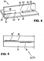
- the two components 10, 11 are plate-shaped and form a T-shaped welding assembly 31.
- a longitudinal edge 32 (cf. Fig. 4 ) of the component 10 (central web) markings 20 are introduced, which are detected by the image recognition system 13.
- the marking 20 is in the form of a sequence (sequence) of triangular, rectangular and / or semicircular or quarter-circular notches milled on the longitudinal edge 32 (recesses 22; cf. Fig. 12 ) whose outlines in Fig. 3 ; Points a) to j) can be seen.
- the weld 19 (fillet) is in Fig. 4 marked with dashed lines.
- the welding robot 18 guides the camera 29 of the image recognition system 13 over / to the components 10, 11 to be connected.
- the position in which the welding head (working tool 14) travels a weld seam 19, 19 '(cf. Figures 4 and 5 ) results from the repetitive training process.
- the welding assembly 31 is automatically turned over by the manipulator 17 to pull the other, second weld seam 19 '.
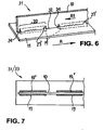
- the markings 20 each lie in the form of a sequence of triangular, rectangular and semicircular notches milled on the longitudinal edge 32 (recesses 22; cf. Fig. 12 ) and each include a starting point 23 '(notches “f” according to Fig. 3 ), a series of semicircles 28 (notches “i” according to Fig. 3 ) and an end point 24 (notch "a” or "b” according to Fig. 3 ).
- the welds 19 are in Fig. 6 marked with dashed lines.
- the number of semicircles 28 corresponds to a thickness (measured in mm) of the weld seam.
- weld seams 19, 19 ′ are drawn in a different order, namely first the two (or more) weld seams 19 one after the other in the direction R on one side of the central web (component 10) and then, after rotation with the manipulator 17, the weld seams 19 'on the other side of the central bridge.
- the welding head (working tool 14) moves when pulling each weld seam 19, 19 'in a direction R1 opposite to the direction R.
- the overall work program of the welding robot created on the basis of the detected markings 20 also defines the sequence of the weld seams 19, 19 ′ to be created.
- predefined conditions can be stored in the data memory, on the basis of which, when a plurality of markings 20 arranged one behind the other are found, an overall work program for the welding robot is generated, in which a weld 19 is first produced on one end of the welding assembly 31 on the front and a weld 19 'on the other side of the welding assembly 31 as the second weld. Then the other welds are made, alternately on each side, if necessary.
- Markings for no-go areas 25 are also provided between the adjacent markings 21 (engravings 27), which markings will be detected by the image recognition system 13 and must not be contacted with the welding head (working tool 14).
- the no-go area 25 is used as a trapezoidal marking Fig. 3 ; Point k).
- the associated control command contains information about which area, based on the marking, may not be contacted.
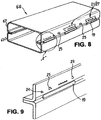
- the welding assembly 34 shown comprises a plate-shaped component 35 and two components 36, 36 'arranged parallel to one another on its flat side in the form of angle profiles, the shorter L-legs 37, 37' of which are directed towards one another.
- the angle profiles 36, 36 'each have a longitudinal edge 38, 38' facing away from the L-leg 37, 37 'with markings 20 (recesses) made thereon, which can be detected by the image recognition system 13.
- angle profiles 36 and 36 are identical parts with identical markings 20 in the form of openings or notches that are visible from both sides of the angle profiles.
- FIG. 10 Marking 20 attached to the longitudinal edge 38 'is shown in FIG Fig. 12 shown in detail and labeled "front”.
- FIG. 10 on the longitudinal edge 38 mark 20 is in Fig. 12 shown in detail and labeled "rear”.
- the Fig. 11 shows two welds 19, 19 '(fillet welds) produced in this way on the outside of the angle profiles 36, 36'.
- a welding assembly 26 can be seen, which the welding assembly 34 and the additional components 39; 40 comprises, namely a plate-shaped tab (component 39) laid flat on the L-legs 37, 37 'and a plate element (component 40) placed upright on an upper side 41 of the tab.
- the component 39 (bracket) is supported with its semicircular end regions 42, 42 'on the L-legs 37, 37'.
- the arcuate welds 19, 19 '(fillet welds) form an overlap joint 44.
- the marking 20 is introduced, which marks a starting point 3 (rectangle “f” according to FIG Fig. 3 ), five semicircles (partial marking "i") and one partial marking "a” or “b” according to Fig. 3 includes as an end point 24.
- the 5mm thick weld seam is only drawn on one side, starting from the starting point 23.
- FIG. 15 Another welding assembly 28, consisting of two C profiles (components 46, 46 ') placed upright on a plate-shaped component 45, shows the Fig. 15 , The C-profiles 46, 46 'are directed towards each other with their longitudinal edges 47, 47' and overlap slightly there.
- markings 20 are introduced which each comprise a starting point 23, five semicircles (partial marking "i") and an end point 24.
- a circumferential weld connection consisting of several interrupted fillet welds is formed.
- the disclosed welding assembly 28 represents a spatial construction which comprises a plate-shaped component 52 (base element), on which other components 53, 54, 55 are arranged in different planes and are to be welded there.
- the plate-shaped component 54 has a recess 56 and two C-legs 55, 55 ', with which the component 52 (base element) is supported.
- a marking 20 is made on a connecting edge 57 of the C-leg 55 with the component 52.
- the component 53 is arranged perpendicular to the component 52 and at the same time to the component 54 and forms a partial support 58 for a further component 59, which comprises three plate elements 60, 61, 62 inclined to one another.
- the one plate element 60 and the second, middle plate element 61 are connected to the component 53 arranged perpendicular to the component 52 (base element) by welding.
- the third plate element 62 penetrates the recess 56 and lies flat on the component 52 (base element).
- the middle, inclined plate element 61 is supported on an equally inclined connecting edge 63 of the component 53.
- the plate-shaped partial support 58 (component 53) comprises three connecting edges 63, 64 and 65.
- the plate element 60 of the component 59 is supported on the connecting edge 64 arranged perpendicular to the component 52 (base element).
- the connecting edge 65 in turn faces the component 52 (base element).
- Markings 20 are introduced on all connecting edges 63, 64, 65 and on the third plate element 62 of component 59.
- the third plate element 62 forms together with the component 52 (base element) an overlap joint, not shown.
- markings 21 (engravings 27) also show the Figures 17 to 19 .
- the laser-engraved markings 21 are introduced on an angular profile 69 along its connecting edge 70 with a plate element 68.
- a rectangle with two semicircles according to Fig. 3 Point d) is recognized by the image recognition system 13 as the starting point 23 for the introduction of a weld seam 19, 19 'on both sides of the angle profile 69.
- the markings 21 are placed on only one side of the angle profile 69. For engravings at a distance from an edge to be welded teaching must be carried out with the appropriate distance or an offset must be defined in the program.
Landscapes
- Engineering & Computer Science (AREA)
- Robotics (AREA)
- Mechanical Engineering (AREA)
- Manipulator (AREA)
- Numerical Control (AREA)
Applications Claiming Priority (1)
| Application Number | Priority Date | Filing Date | Title |
|---|---|---|---|
| DE102018114867.4A DE102018114867A1 (de) | 2018-06-20 | 2018-06-20 | Verfahren zum Verbinden von Bauteilen |
Publications (1)
| Publication Number | Publication Date |
|---|---|
| EP3584041A1 true EP3584041A1 (fr) | 2019-12-25 |
Family
ID=67070516
Family Applications (1)
| Application Number | Title | Priority Date | Filing Date |
|---|---|---|---|
| EP19000294.9A Withdrawn EP3584041A1 (fr) | 2018-06-20 | 2019-06-17 | Procédé de raccordement de composants |
Country Status (2)
| Country | Link |
|---|---|
| EP (1) | EP3584041A1 (fr) |
| DE (1) | DE102018114867A1 (fr) |
Cited By (3)
| Publication number | Priority date | Publication date | Assignee | Title |
|---|---|---|---|---|
| CN113954072A (zh) * | 2021-11-05 | 2022-01-21 | 中国矿业大学 | 一种视觉引导的木门工件智能识别定位系统及方法 |
| CN115213573A (zh) * | 2022-08-23 | 2022-10-21 | 大族激光科技产业集团股份有限公司 | 采用平面激光切割设备加工沉头孔的方法、设备及介质 |
| WO2024115044A1 (fr) * | 2022-11-28 | 2024-06-06 | Lisa Dräxlmaier GmbH | Procédé et dispositif de contrôle d'une jonction |
Families Citing this family (2)
| Publication number | Priority date | Publication date | Assignee | Title |
|---|---|---|---|---|
| CN112935649A (zh) * | 2021-01-23 | 2021-06-11 | 佛山市广凡机器人有限公司 | 一种全方位转向型焊接机器人及其使用方法 |
| DE102021124053A1 (de) | 2021-09-17 | 2023-03-23 | Bayerische Motoren Werke Aktiengesellschaft | Verfahren zum Bereitstellen von Informationen für eine Robotereinrichtung sowie elektronische Recheneinrichtung |
Citations (6)
| Publication number | Priority date | Publication date | Assignee | Title |
|---|---|---|---|---|
| DE102004043075A1 (de) * | 2003-09-17 | 2005-04-21 | Daimler Chrysler Ag | Verfahren zum Vorausbestimmen der Bearbeitungspositionen eines Laserstrahls |
| WO2012094689A1 (fr) | 2011-01-10 | 2012-07-19 | Fronius International Gmbh | Procédé d'apprentissage/de test de la séquence de mouvements d'un robot de soudage, robot de soudage et commande associée |
| DE102011005004A1 (de) | 2011-03-03 | 2012-09-06 | Brose Fahrzeugteile Gmbh & Co. Kommanditgesellschaft, Coburg | Verfahren zur Überwachung eines Lateralversatzes eines Ist-Schweißnahtverlaufs bezüglich eines Soll-Schweißnahtverlaufs, Baugruppe sowie Kraftfahrzeugssitz |
| US20140277679A1 (en) * | 2013-03-15 | 2014-09-18 | Northeastern University | Systems and Methods of using a Hieroglyphic Machine Interface Language for Communication with Auxiliary Robotics in Rapid Fabrication Environments |
| WO2017020879A1 (fr) * | 2015-07-31 | 2017-02-09 | Dallmeier Electronic Gmbh & Co. Kg | Système pour observer et influencer des objets d'intérêt ainsi que des processus exécutés par ceux-ci et procédé correspondant |
| EP2435217B1 (fr) * | 2009-05-27 | 2017-08-16 | Leica Geosystems AG | Procédé et système destinés au positionnement très précis d'au moins un objet dans une position finale dans l' espace |
Family Cites Families (3)
| Publication number | Priority date | Publication date | Assignee | Title |
|---|---|---|---|---|
| DE10351669B4 (de) * | 2003-11-05 | 2012-09-13 | Kuka Laboratories Gmbh | Verfahren und Vorrichtung zum Steuern eines Handhabungsgeräts relativ zu einem Objekt |
| DE102007037078B4 (de) * | 2007-08-06 | 2022-01-27 | Kuka Roboter Gmbh | Verfahren zur Einhaltung von Arbeitsraumgrenzen eines Arbeitsmittels eines Roboters |
| ES2818918T3 (es) * | 2008-05-21 | 2021-04-14 | Fft Edag Produktionssysteme Gmbh & Co Kg | Unión de componentes sin marcos de fijación |
-
2018
- 2018-06-20 DE DE102018114867.4A patent/DE102018114867A1/de not_active Withdrawn
-
2019
- 2019-06-17 EP EP19000294.9A patent/EP3584041A1/fr not_active Withdrawn
Patent Citations (6)
| Publication number | Priority date | Publication date | Assignee | Title |
|---|---|---|---|---|
| DE102004043075A1 (de) * | 2003-09-17 | 2005-04-21 | Daimler Chrysler Ag | Verfahren zum Vorausbestimmen der Bearbeitungspositionen eines Laserstrahls |
| EP2435217B1 (fr) * | 2009-05-27 | 2017-08-16 | Leica Geosystems AG | Procédé et système destinés au positionnement très précis d'au moins un objet dans une position finale dans l' espace |
| WO2012094689A1 (fr) | 2011-01-10 | 2012-07-19 | Fronius International Gmbh | Procédé d'apprentissage/de test de la séquence de mouvements d'un robot de soudage, robot de soudage et commande associée |
| DE102011005004A1 (de) | 2011-03-03 | 2012-09-06 | Brose Fahrzeugteile Gmbh & Co. Kommanditgesellschaft, Coburg | Verfahren zur Überwachung eines Lateralversatzes eines Ist-Schweißnahtverlaufs bezüglich eines Soll-Schweißnahtverlaufs, Baugruppe sowie Kraftfahrzeugssitz |
| US20140277679A1 (en) * | 2013-03-15 | 2014-09-18 | Northeastern University | Systems and Methods of using a Hieroglyphic Machine Interface Language for Communication with Auxiliary Robotics in Rapid Fabrication Environments |
| WO2017020879A1 (fr) * | 2015-07-31 | 2017-02-09 | Dallmeier Electronic Gmbh & Co. Kg | Système pour observer et influencer des objets d'intérêt ainsi que des processus exécutés par ceux-ci et procédé correspondant |
Cited By (4)
| Publication number | Priority date | Publication date | Assignee | Title |
|---|---|---|---|---|
| CN113954072A (zh) * | 2021-11-05 | 2022-01-21 | 中国矿业大学 | 一种视觉引导的木门工件智能识别定位系统及方法 |
| CN113954072B (zh) * | 2021-11-05 | 2024-05-28 | 中国矿业大学 | 一种视觉引导的木门工件智能识别定位系统及方法 |
| CN115213573A (zh) * | 2022-08-23 | 2022-10-21 | 大族激光科技产业集团股份有限公司 | 采用平面激光切割设备加工沉头孔的方法、设备及介质 |
| WO2024115044A1 (fr) * | 2022-11-28 | 2024-06-06 | Lisa Dräxlmaier GmbH | Procédé et dispositif de contrôle d'une jonction |
Also Published As
| Publication number | Publication date |
|---|---|
| DE102018114867A1 (de) | 2019-12-24 |
Similar Documents
| Publication | Publication Date | Title |
|---|---|---|
| EP3584041A1 (fr) | Procédé de raccordement de composants | |
| DE10242710A1 (de) | Verfahren zum Herstellen eines Verbindungsbereiches auf einem Werkstück | |
| EP1681111A1 (fr) | Dispositif de fabrication, notamment presse de pliage, et méthode d'utilisation de ce dispositif | |
| DE69431930T2 (de) | Vorrichtung zum automatisch Wechseln von Werkzeugen in einer Biegevorrichtung | |
| DE102004010312A1 (de) | Verfahren zum Einmessen eines Arbeitspunktes | |
| WO2015019285A1 (fr) | Presse à plier | |
| DE102007033309A1 (de) | Verfahren zum Bearbeiten einer Kontur an wenigstens einem Werkstück mittels eines Roboters | |
| EP3528993A1 (fr) | Choix de technologie basé sur des images pour soudure au laser | |
| WO2013166538A1 (fr) | Procédé de manipulation automatisée d'un outil de cintrage et dispositif de fabrication | |
| DE102010015031A1 (de) | Verfahren und Vorrichtung zur lagegenauen Durchführung eines Bearbeitungsprozesses an einer Kraftfahrzeugkomponente | |
| DE202010008808U1 (de) | Bearbeitungswerkzeug | |
| DE102007062109A1 (de) | Industrieroboter und Verfahren zum Steuern eines Industrieroboters | |
| DE102007035485A1 (de) | Laserschweißvorrichtung zum Fügen von Bauteilen | |
| DE102009058817A1 (de) | Anlage und Verfahren zum maßhaltigen Rollfalzen eines Bauteils | |
| DE202017102466U1 (de) | Vorrichtung zur Erkennung der genauen Position und Lage eines Bauteils in einer Bearbeitungsstation | |
| DE102015119424A1 (de) | Verfahren zum Bearbeiten zumindest eines Werkstücks | |
| DE102019201723A1 (de) | Verfahren zum Einrichten einer Werkzeugmaschine und Fertigungssystem | |
| DE102021121314B3 (de) | System zum Fügen von Bauteilen | |
| DE19712421C1 (de) | Verfahren und Vorrichtung zur genauen Bestimmung des Nadel-Nullpunktes der Nähmaschine eines Nähautomaten | |
| DE102019131401B3 (de) | Kalibrierung einer Impedanzregelung eines Robotermanipulators | |
| EP1261958B1 (fr) | Procede et dispositif permettant de soutenir une personne lors de l'execution de processus de travail exigeant de la precision | |
| EP1635972A1 (fr) | Procede et dispositif pour travailler des pieces par formage | |
| DE10242769C1 (de) | Verfahren zur Vermessung der Lage von robotergeführten Werkstücken und Messeinrichtung hierzu | |
| DE102023105361B3 (de) | Verfahren zum Kalibrieren eines Lichtschnittsensors und zugehöriges Robotersystem | |
| DE102019123045A1 (de) | Dummy-Vorrichtung und deren Verwendungen sowie Automatisierungssystem |
Legal Events
| Date | Code | Title | Description |
|---|---|---|---|
| PUAI | Public reference made under article 153(3) epc to a published international application that has entered the european phase |
Free format text: ORIGINAL CODE: 0009012 |
|
| AK | Designated contracting states |
Kind code of ref document: A1 Designated state(s): AL AT BE BG CH CY CZ DE DK EE ES FI FR GB GR HR HU IE IS IT LI LT LU LV MC MK MT NL NO PL PT RO RS SE SI SK SM TR |
|
| AX | Request for extension of the european patent |
Extension state: BA ME |
|
| STAA | Information on the status of an ep patent application or granted ep patent |
Free format text: STATUS: THE APPLICATION IS DEEMED TO BE WITHDRAWN |
|
| 18D | Application deemed to be withdrawn |
Effective date: 20200626 |