EP3584101A2 - Hybridantriebsfahrzeug, hybridantriebsfahrsystem und getriebe - Google Patents
Hybridantriebsfahrzeug, hybridantriebsfahrsystem und getriebe Download PDFInfo
- Publication number
- EP3584101A2 EP3584101A2 EP19179419.7A EP19179419A EP3584101A2 EP 3584101 A2 EP3584101 A2 EP 3584101A2 EP 19179419 A EP19179419 A EP 19179419A EP 3584101 A2 EP3584101 A2 EP 3584101A2
- Authority
- EP
- European Patent Office
- Prior art keywords
- gear
- toothed gear
- electric motor
- driven
- driving
- Prior art date
- Legal status (The legal status is an assumption and is not a legal conclusion. Google has not performed a legal analysis and makes no representation as to the accuracy of the status listed.)
- Granted
Links
Images



Classifications
-
- B—PERFORMING OPERATIONS; TRANSPORTING
- B60—VEHICLES IN GENERAL
- B60K—ARRANGEMENT OR MOUNTING OF PROPULSION UNITS OR OF TRANSMISSIONS IN VEHICLES; ARRANGEMENT OR MOUNTING OF PLURAL DIVERSE PRIME-MOVERS IN VEHICLES; AUXILIARY DRIVES FOR VEHICLES; INSTRUMENTATION OR DASHBOARDS FOR VEHICLES; ARRANGEMENTS IN CONNECTION WITH COOLING, AIR INTAKE, GAS EXHAUST OR FUEL SUPPLY OF PROPULSION UNITS IN VEHICLES
- B60K6/00—Arrangement or mounting of plural diverse prime-movers for mutual or common propulsion, e.g. hybrid propulsion systems comprising electric motors and internal combustion engines
- B60K6/20—Arrangement or mounting of plural diverse prime-movers for mutual or common propulsion, e.g. hybrid propulsion systems comprising electric motors and internal combustion engines the prime-movers consisting of electric motors and internal combustion engines, e.g. HEVs
- B60K6/50—Architecture of the driveline characterised by arrangement or kind of transmission units
-
- B—PERFORMING OPERATIONS; TRANSPORTING
- B60—VEHICLES IN GENERAL
- B60K—ARRANGEMENT OR MOUNTING OF PROPULSION UNITS OR OF TRANSMISSIONS IN VEHICLES; ARRANGEMENT OR MOUNTING OF PLURAL DIVERSE PRIME-MOVERS IN VEHICLES; AUXILIARY DRIVES FOR VEHICLES; INSTRUMENTATION OR DASHBOARDS FOR VEHICLES; ARRANGEMENTS IN CONNECTION WITH COOLING, AIR INTAKE, GAS EXHAUST OR FUEL SUPPLY OF PROPULSION UNITS IN VEHICLES
- B60K6/00—Arrangement or mounting of plural diverse prime-movers for mutual or common propulsion, e.g. hybrid propulsion systems comprising electric motors and internal combustion engines
- B60K6/20—Arrangement or mounting of plural diverse prime-movers for mutual or common propulsion, e.g. hybrid propulsion systems comprising electric motors and internal combustion engines the prime-movers consisting of electric motors and internal combustion engines, e.g. HEVs
- B60K6/22—Arrangement or mounting of plural diverse prime-movers for mutual or common propulsion, e.g. hybrid propulsion systems comprising electric motors and internal combustion engines the prime-movers consisting of electric motors and internal combustion engines, e.g. HEVs characterised by apparatus, components or means specially adapted for HEVs
- B60K6/36—Arrangement or mounting of plural diverse prime-movers for mutual or common propulsion, e.g. hybrid propulsion systems comprising electric motors and internal combustion engines the prime-movers consisting of electric motors and internal combustion engines, e.g. HEVs characterised by apparatus, components or means specially adapted for HEVs characterised by the transmission gearings
-
- B—PERFORMING OPERATIONS; TRANSPORTING
- B60—VEHICLES IN GENERAL
- B60K—ARRANGEMENT OR MOUNTING OF PROPULSION UNITS OR OF TRANSMISSIONS IN VEHICLES; ARRANGEMENT OR MOUNTING OF PLURAL DIVERSE PRIME-MOVERS IN VEHICLES; AUXILIARY DRIVES FOR VEHICLES; INSTRUMENTATION OR DASHBOARDS FOR VEHICLES; ARRANGEMENTS IN CONNECTION WITH COOLING, AIR INTAKE, GAS EXHAUST OR FUEL SUPPLY OF PROPULSION UNITS IN VEHICLES
- B60K6/00—Arrangement or mounting of plural diverse prime-movers for mutual or common propulsion, e.g. hybrid propulsion systems comprising electric motors and internal combustion engines
- B60K6/20—Arrangement or mounting of plural diverse prime-movers for mutual or common propulsion, e.g. hybrid propulsion systems comprising electric motors and internal combustion engines the prime-movers consisting of electric motors and internal combustion engines, e.g. HEVs
- B60K6/42—Arrangement or mounting of plural diverse prime-movers for mutual or common propulsion, e.g. hybrid propulsion systems comprising electric motors and internal combustion engines the prime-movers consisting of electric motors and internal combustion engines, e.g. HEVs characterised by the architecture of the hybrid electric vehicle
- B60K6/48—Parallel type
-
- B—PERFORMING OPERATIONS; TRANSPORTING
- B60—VEHICLES IN GENERAL
- B60K—ARRANGEMENT OR MOUNTING OF PROPULSION UNITS OR OF TRANSMISSIONS IN VEHICLES; ARRANGEMENT OR MOUNTING OF PLURAL DIVERSE PRIME-MOVERS IN VEHICLES; AUXILIARY DRIVES FOR VEHICLES; INSTRUMENTATION OR DASHBOARDS FOR VEHICLES; ARRANGEMENTS IN CONNECTION WITH COOLING, AIR INTAKE, GAS EXHAUST OR FUEL SUPPLY OF PROPULSION UNITS IN VEHICLES
- B60K6/00—Arrangement or mounting of plural diverse prime-movers for mutual or common propulsion, e.g. hybrid propulsion systems comprising electric motors and internal combustion engines
- B60K6/20—Arrangement or mounting of plural diverse prime-movers for mutual or common propulsion, e.g. hybrid propulsion systems comprising electric motors and internal combustion engines the prime-movers consisting of electric motors and internal combustion engines, e.g. HEVs
- B60K6/50—Architecture of the driveline characterised by arrangement or kind of transmission units
- B60K6/54—Transmission for changing ratio
- B60K6/547—Transmission for changing ratio the transmission being a stepped gearing
-
- B—PERFORMING OPERATIONS; TRANSPORTING
- B60—VEHICLES IN GENERAL
- B60W—CONJOINT CONTROL OF VEHICLE SUB-UNITS OF DIFFERENT TYPE OR DIFFERENT FUNCTION; CONTROL SYSTEMS SPECIALLY ADAPTED FOR HYBRID VEHICLES; ROAD VEHICLE DRIVE CONTROL SYSTEMS FOR PURPOSES NOT RELATED TO THE CONTROL OF A PARTICULAR SUB-UNIT
- B60W10/00—Conjoint control of vehicle sub-units of different type or different function
- B60W10/10—Conjoint control of vehicle sub-units of different type or different function including control of change-speed gearings
-
- F—MECHANICAL ENGINEERING; LIGHTING; HEATING; WEAPONS; BLASTING
- F16—ENGINEERING ELEMENTS AND UNITS; GENERAL MEASURES FOR PRODUCING AND MAINTAINING EFFECTIVE FUNCTIONING OF MACHINES OR INSTALLATIONS; THERMAL INSULATION IN GENERAL
- F16H—GEARING
- F16H3/00—Toothed gearings for conveying rotary motion with variable gear ratio or for reversing rotary motion
- F16H3/02—Toothed gearings for conveying rotary motion with variable gear ratio or for reversing rotary motion without gears having orbital motion
- F16H3/08—Toothed gearings for conveying rotary motion with variable gear ratio or for reversing rotary motion without gears having orbital motion exclusively or essentially with continuously meshing gears, that can be disengaged from their shafts
- F16H3/087—Toothed gearings for conveying rotary motion with variable gear ratio or for reversing rotary motion without gears having orbital motion exclusively or essentially with continuously meshing gears, that can be disengaged from their shafts characterised by the disposition of the gears
- F16H3/093—Toothed gearings for conveying rotary motion with variable gear ratio or for reversing rotary motion without gears having orbital motion exclusively or essentially with continuously meshing gears, that can be disengaged from their shafts characterised by the disposition of the gears with two or more countershafts
-
- F—MECHANICAL ENGINEERING; LIGHTING; HEATING; WEAPONS; BLASTING
- F16—ENGINEERING ELEMENTS AND UNITS; GENERAL MEASURES FOR PRODUCING AND MAINTAINING EFFECTIVE FUNCTIONING OF MACHINES OR INSTALLATIONS; THERMAL INSULATION IN GENERAL
- F16H—GEARING
- F16H61/00—Control functions within control units of change-speed- or reversing-gearings for conveying rotary motion ; Control of exclusively fluid gearing, friction gearing, gearings with endless flexible members or other particular types of gearing
- F16H61/70—Control functions within control units of change-speed- or reversing-gearings for conveying rotary motion ; Control of exclusively fluid gearing, friction gearing, gearings with endless flexible members or other particular types of gearing specially adapted for change-speed gearing in group arrangement, i.e. with separate change-speed gear trains arranged in series, e.g. range or overdrive-type gearing arrangements
-
- B—PERFORMING OPERATIONS; TRANSPORTING
- B60—VEHICLES IN GENERAL
- B60K—ARRANGEMENT OR MOUNTING OF PROPULSION UNITS OR OF TRANSMISSIONS IN VEHICLES; ARRANGEMENT OR MOUNTING OF PLURAL DIVERSE PRIME-MOVERS IN VEHICLES; AUXILIARY DRIVES FOR VEHICLES; INSTRUMENTATION OR DASHBOARDS FOR VEHICLES; ARRANGEMENTS IN CONNECTION WITH COOLING, AIR INTAKE, GAS EXHAUST OR FUEL SUPPLY OF PROPULSION UNITS IN VEHICLES
- B60K6/00—Arrangement or mounting of plural diverse prime-movers for mutual or common propulsion, e.g. hybrid propulsion systems comprising electric motors and internal combustion engines
- B60K6/20—Arrangement or mounting of plural diverse prime-movers for mutual or common propulsion, e.g. hybrid propulsion systems comprising electric motors and internal combustion engines the prime-movers consisting of electric motors and internal combustion engines, e.g. HEVs
- B60K6/42—Arrangement or mounting of plural diverse prime-movers for mutual or common propulsion, e.g. hybrid propulsion systems comprising electric motors and internal combustion engines the prime-movers consisting of electric motors and internal combustion engines, e.g. HEVs characterised by the architecture of the hybrid electric vehicle
- B60K6/48—Parallel type
- B60K2006/4808—Electric machine connected or connectable to gearbox output shaft
-
- B—PERFORMING OPERATIONS; TRANSPORTING
- B60—VEHICLES IN GENERAL
- B60K—ARRANGEMENT OR MOUNTING OF PROPULSION UNITS OR OF TRANSMISSIONS IN VEHICLES; ARRANGEMENT OR MOUNTING OF PLURAL DIVERSE PRIME-MOVERS IN VEHICLES; AUXILIARY DRIVES FOR VEHICLES; INSTRUMENTATION OR DASHBOARDS FOR VEHICLES; ARRANGEMENTS IN CONNECTION WITH COOLING, AIR INTAKE, GAS EXHAUST OR FUEL SUPPLY OF PROPULSION UNITS IN VEHICLES
- B60K6/00—Arrangement or mounting of plural diverse prime-movers for mutual or common propulsion, e.g. hybrid propulsion systems comprising electric motors and internal combustion engines
- B60K6/20—Arrangement or mounting of plural diverse prime-movers for mutual or common propulsion, e.g. hybrid propulsion systems comprising electric motors and internal combustion engines the prime-movers consisting of electric motors and internal combustion engines, e.g. HEVs
- B60K6/42—Arrangement or mounting of plural diverse prime-movers for mutual or common propulsion, e.g. hybrid propulsion systems comprising electric motors and internal combustion engines the prime-movers consisting of electric motors and internal combustion engines, e.g. HEVs characterised by the architecture of the hybrid electric vehicle
- B60K6/48—Parallel type
- B60K2006/4825—Electric machine connected or connectable to gearbox input shaft
-
- B—PERFORMING OPERATIONS; TRANSPORTING
- B60—VEHICLES IN GENERAL
- B60K—ARRANGEMENT OR MOUNTING OF PROPULSION UNITS OR OF TRANSMISSIONS IN VEHICLES; ARRANGEMENT OR MOUNTING OF PLURAL DIVERSE PRIME-MOVERS IN VEHICLES; AUXILIARY DRIVES FOR VEHICLES; INSTRUMENTATION OR DASHBOARDS FOR VEHICLES; ARRANGEMENTS IN CONNECTION WITH COOLING, AIR INTAKE, GAS EXHAUST OR FUEL SUPPLY OF PROPULSION UNITS IN VEHICLES
- B60K6/00—Arrangement or mounting of plural diverse prime-movers for mutual or common propulsion, e.g. hybrid propulsion systems comprising electric motors and internal combustion engines
- B60K6/20—Arrangement or mounting of plural diverse prime-movers for mutual or common propulsion, e.g. hybrid propulsion systems comprising electric motors and internal combustion engines the prime-movers consisting of electric motors and internal combustion engines, e.g. HEVs
- B60K6/42—Arrangement or mounting of plural diverse prime-movers for mutual or common propulsion, e.g. hybrid propulsion systems comprising electric motors and internal combustion engines the prime-movers consisting of electric motors and internal combustion engines, e.g. HEVs characterised by the architecture of the hybrid electric vehicle
- B60K6/48—Parallel type
- B60K2006/4833—Step up or reduction gearing driving generator, e.g. to operate generator in most efficient speed range
- B60K2006/4841—Step up or reduction gearing driving generator, e.g. to operate generator in most efficient speed range the gear provides shifting between multiple ratios
-
- F—MECHANICAL ENGINEERING; LIGHTING; HEATING; WEAPONS; BLASTING
- F16—ENGINEERING ELEMENTS AND UNITS; GENERAL MEASURES FOR PRODUCING AND MAINTAINING EFFECTIVE FUNCTIONING OF MACHINES OR INSTALLATIONS; THERMAL INSULATION IN GENERAL
- F16H—GEARING
- F16H3/00—Toothed gearings for conveying rotary motion with variable gear ratio or for reversing rotary motion
- F16H3/02—Toothed gearings for conveying rotary motion with variable gear ratio or for reversing rotary motion without gears having orbital motion
- F16H3/08—Toothed gearings for conveying rotary motion with variable gear ratio or for reversing rotary motion without gears having orbital motion exclusively or essentially with continuously meshing gears, that can be disengaged from their shafts
- F16H2003/0822—Toothed gearings for conveying rotary motion with variable gear ratio or for reversing rotary motion without gears having orbital motion exclusively or essentially with continuously meshing gears, that can be disengaged from their shafts characterised by the arrangement of at least one reverse gear
-
- F—MECHANICAL ENGINEERING; LIGHTING; HEATING; WEAPONS; BLASTING
- F16—ENGINEERING ELEMENTS AND UNITS; GENERAL MEASURES FOR PRODUCING AND MAINTAINING EFFECTIVE FUNCTIONING OF MACHINES OR INSTALLATIONS; THERMAL INSULATION IN GENERAL
- F16H—GEARING
- F16H3/00—Toothed gearings for conveying rotary motion with variable gear ratio or for reversing rotary motion
- F16H3/02—Toothed gearings for conveying rotary motion with variable gear ratio or for reversing rotary motion without gears having orbital motion
- F16H3/08—Toothed gearings for conveying rotary motion with variable gear ratio or for reversing rotary motion without gears having orbital motion exclusively or essentially with continuously meshing gears, that can be disengaged from their shafts
- F16H3/087—Toothed gearings for conveying rotary motion with variable gear ratio or for reversing rotary motion without gears having orbital motion exclusively or essentially with continuously meshing gears, that can be disengaged from their shafts characterised by the disposition of the gears
- F16H3/093—Toothed gearings for conveying rotary motion with variable gear ratio or for reversing rotary motion without gears having orbital motion exclusively or essentially with continuously meshing gears, that can be disengaged from their shafts characterised by the disposition of the gears with two or more countershafts
- F16H2003/0931—Toothed gearings for conveying rotary motion with variable gear ratio or for reversing rotary motion without gears having orbital motion exclusively or essentially with continuously meshing gears, that can be disengaged from their shafts characterised by the disposition of the gears with two or more countershafts each countershaft having an output gear meshing with a single common gear on the output shaft
-
- F—MECHANICAL ENGINEERING; LIGHTING; HEATING; WEAPONS; BLASTING
- F16—ENGINEERING ELEMENTS AND UNITS; GENERAL MEASURES FOR PRODUCING AND MAINTAINING EFFECTIVE FUNCTIONING OF MACHINES OR INSTALLATIONS; THERMAL INSULATION IN GENERAL
- F16H—GEARING
- F16H2200/00—Transmissions for multiple ratios
- F16H2200/003—Transmissions for multiple ratios characterised by the number of forward speeds
- F16H2200/0047—Transmissions for multiple ratios characterised by the number of forward speeds the gear ratios comprising five forward speeds
-
- Y—GENERAL TAGGING OF NEW TECHNOLOGICAL DEVELOPMENTS; GENERAL TAGGING OF CROSS-SECTIONAL TECHNOLOGIES SPANNING OVER SEVERAL SECTIONS OF THE IPC; TECHNICAL SUBJECTS COVERED BY FORMER USPC CROSS-REFERENCE ART COLLECTIONS [XRACs] AND DIGESTS
- Y02—TECHNOLOGIES OR APPLICATIONS FOR MITIGATION OR ADAPTATION AGAINST CLIMATE CHANGE
- Y02T—CLIMATE CHANGE MITIGATION TECHNOLOGIES RELATED TO TRANSPORTATION
- Y02T10/00—Road transport of goods or passengers
- Y02T10/60—Other road transportation technologies with climate change mitigation effect
- Y02T10/62—Hybrid vehicles
Definitions
- the present application relates to the technical field of vehicles, and specifically relates to a hybrid power vehicle, a hybrid power driving system and a gear box for the hybrid power vehicle.
- a traditional vehicle industry uses fossil oil as fuel in the modern society. Although the traditional vehicle industry can provide a quick and comfortable means of transportation for people, it also increases the dependence of national energy on the fossil energy and deepens the contradiction between the energy production and consumption. With the constant increasing of double pressure of resources and environment, it is a trend for the future vehicle industry to develop new energy vehicles.
- a hybrid power vehicle As a branch of the new energy vehicles, a hybrid power vehicle has several advantages of low emission pollution, long driving range, saving energy and keeping using the existing basic facilities, and thus is widely used.
- the power assembly of the conventional hybrid power vehicle has the disadvantages of occupying a large space, having a high cost of double electrical motors, a low efficiency of the cooperation between the internal combustion engine and the electric motor, and a poor fuel economy. Therefore, it is of a significant developing value to develop a hybrid power system of a superior overall performance by improving the structure of the power assembly of the hybrid power system.
- a patent document No. CN107599818A describes a double clutch gear box, in which two input shafts are connected to the internal combustion engine by two clutches for transmission, and an electrical motor can output power using all gears of the original double clutch gear box.
- Such gear box has a complicated structure, and a complex cooperative operation between the internal combustion engine and the electric motor.
- a patent document No. CN202283873U describes a transmission system for a hybrid electric vehicle, in which a first gear and a second gear of an internal combustion engine are omitted and replaced by gears of the electric motor. In this transmission system, the cooperative operation between the internal combustion engine and the electric motor is defective.
- An object of the present application is to provide a hybrid power vehicle, a hybrid power driving system and a gear box for the hybrid power vehicle, in which the gear box can be effectively downsized, and thus the space occupied by the hybrid power driving system including the gear box can be reduced, the cost thereof can also be reduced, and also the cooperating efficiency between the internal combustion engine and the electric motor can be improved.
- a gear box used for a hybrid power vehicle wherein the gear box includes a first gear box part and a second gear box part, the first gear box part includes four forward gears, i.e. a first gear to a fourth gear, or includes fifth forward gears, i.e.
- the first gear box part includes just one input shaft and just two intermediate shafts, the input shaft is configured to be connected to an internal combustion engine for transmission, a first driving toothed gear and a second driving toothed gear are provided on the input shaft, a first driven toothed gear engageable with the first driving toothed gear and a second driven toothed gear engageable with the second driving toothed gear are provided on a first intermediate shaft of the two intermediate shafts, a third driven toothed gear engageable with the first driving toothed gear and a fourth driven toothed gear engageable with the second driving toothed gear are provided on a second intermediate shaft of the two intermediate shafts, the first to the fourth driven gears are respectively nested toothed gears and form one of the four forward gears of the five forward gears together with the respective driving toothed gears, in case of five forward gears, another gear other than the four
- the first driving toothed gear is a fixedly connected toothed gear or a nested toothed gear; and/or the second driving toothed gear is a fixedly connected toothed gear or a nested toothed gear.
- a synchronizer for the first driven toothed gear and a synchronizer for the second driven toothed gear form a first two-way synchronizer located on the first intermediate shaft between the first driven toothed gear and the second driven toothed gear; and/or a synchronizer for the third driven toothed gear and a synchronizer for the fourth driven toothed gear form a second two-way synchronizer located on the second intermediate shaft between the third driven toothed gear and the fourth driven toothed gear.
- the third driving toothed gear and the fifth driven toothed gear form five gears.
- the third driving toothed gear and the fifth driven toothed gear also can form the first gear, the second gear, the third gear, the fourth gear or the fifth gear.
- first driving toothed gear and the second driven toothed gear form the first gear
- first driving toothed gear and the third driven toothed gear form the third gear
- second driving toothed gear and the second driven toothed gear form the second gear
- the second driving toothed gear and the fourth driven toothed gear forms the fourth gear
- the first driving toothed gear and the second driving toothed gear are arranged in a listed sequence or in an inverted sequence on the input shaft from a side towards the internal combustion engine and a side away from the internal combustion engine; and the third driving toothed gear is arranged on a side towards the internal combustion engine or away from the internal combustion engine relative to the first driving toothed gear and the second driving toothed gear, or is arranged between the first driving toothed gear and the second driving toothed gear.
- the input shaft is configured to be connected to the internal combustion engine via a clutch or a hydraulic torque converter for transmission.
- a differential is integrated into the gear box, and the first main reduction toothed gear and the second main reduction toothed gear engage with a differential toothed gear of the differential; or the input shaft is configured to be connected to a main speed reducer and the differential via a transmission shaft for transmission.
- the electric motor is integrated into the gear box.
- the first gear box part has a reverse gear.
- the input shaft is provided with a reverse gear driving toothed gear
- the first intermediate shaft and the second intermediate shaft is provided with a reverse gear driven toothed gear
- the reverse gear driving toothed gear is transmissively connected to the reverse driven gear via an intermediate toothed gear
- the intermediate toothed gear is a driving toothed gear of a gear of the electric motor
- the reverse gear driven toothed gear is a driven toothed gear of the gear of the electric motor
- the intermediate toothed gear is an idle toothed gear
- the reverse gear driven toothed gear is a driven toothed gear of the gear of the electric motor.
- the said gear of the electric motor is a first gear or a second gear of the electric motor.
- the third driving toothed gear is a nested toothed gear
- the reverse gear driving toothed gear is a nested toothed gear
- a synchronizer for the third driving toothed gear and a synchronizer for the reverse gear driving toothed gear form a third two-way synchronizer located on the input shaft between the third driving toothed gear and the reverse gear driving toothed gear.
- a driving toothed gear of a second gear of the electric motor is provided on the third intermediate shaft, and the one intermediate shaft is provided with a second driven toothed gear of the second gear of the electric motor.
- the driven toothed gear of the first gear of the electric motor and the second driven toothed gear of the second gear of the electric motor are respectively nested toothed gears, and a synchronizer for the driven toothed gear of the first gear of the electric motor and a synchronizer for the second driven toothed gear of the second gear of the electric motor form a fourth two-way synchronizer located on the said intermediate shaft between the driven toothed gear of the first gear of the electric motor and the second driven toothed gear of the second gear of the electric motor.
- one driving toothed gear of the gear of the electric motor and the third driving toothed gear are arranged on the same axial position.
- one driving toothed gear of the gear of the electric motor and the reverse gear driving toothed gear are arranged on the same axial position.
- the gear of the electric motor is arranged on a side towards the internal combustion engine, while the forward gears are arranged on a side away from the internal combustion engine; or, the forward gears are arranged on a side towards the internal combustion engine, and the gear of the electric motor is arranged on a side away from the internal combustion engine.
- the rotor shaft of the electric motor is parallel staggered relative to any one of the input shaft, the first intermediate shaft, the second intermediate shaft and the third intermediate shaft.
- the gear box is capable of operating in any of the following operating modes:
- the hybrid drive mode is achieved by any forward gear and any gear of the electric motor.
- the charging mode includes: an idle charging operating mode, wherein a power transmission path from the input shaft to the electric motor includes a reverse gear driving toothed gear and a driving toothed gear of one gear of the electric motor; and a driving charging operating mode, wherein the power transmission path from the input shaft to the electric motor includes a driving toothed gear and a driven toothed gear of one forward gear, the first main reduction toothed gear and the second main reduction toothed gear, and a driven toothed gear and a driving toothed gear of one gear of the electric motor.
- the driving toothed gear of the first gear and the third gear as the first driving toothed gear and the driving toothed gear of the second gear and the fourth gear as the second driving toothed gear are fixedly arranged in a listed sequence from a side of the input shaft towards the internal combustion engine to a side of the input shaft away from the internal combustion engine;
- the first main reduction toothed gear, the driven toothed gear of the first gear as the first driven toothed gear, a first two-way synchronizer and the driven toothed gear of the second gear as the second driven toothed gear are arranged in a listed sequence from a side of the first intermediate shaft towards the internal combustion engine to a side of the first intermediate shaft away from the internal combustion engine;
- the second main reduction toothed gear, the driven toothed gear of the third gear as the third driven toothed gear, a second two-way synchronizer, the driven toothed gear of the fourth gear as the fourth driven toothed gear and the driven toothed gear of the first gear of the electric motor are
- the input shaft is further provided with a first synchronizer and a reverse gear driving toothed gear
- the first synchronizer is engageable with the reverse gear driving toothed gear, which engages with the driving toothed gear of the first gear of the electric motor.
- the gear box further includes an idle toothed gear shaft of the reverse gear and an idle toothed gear provided on the idle toothed gear shaft of the reverse gear, and the input shaft is further provided with the first synchronizer and the reverse gear driving toothed gear; and the idle toothed gear engages with the reverse gear driving toothed gear and the driven toothed gear of the first gear of the electric motor respectively.
- the input shaft is further provided with a driving toothed gear of the fifth gear as the third driving toothed gear
- the first synchronizer is a component of a third two-way synchronizer, which can engage with the driving toothed gear of the fifth gear or the reverse gear driving toothed gear
- the first intermediate shaft or the second intermediate shaft is provided with a driven toothed gear of the fifth gear as the fifth driven toothed gear fitted with the driving toothed gear of the fifth gear.
- the driven toothed gear of the first gear of the electric motor is a fixedly connected toothed gear fixedly arranged on the second intermediate shaft; and the driven toothed gear of the first gear of the electric motor is a nested toothed gear sleeved on the second intermediate shaft, and the second intermediate shaft is provided with a second synchronizer for the driven toothed gear of the first gear.
- the third intermediate shaft is further provided with a driving toothed gear of the second gear of the electric motor, and the second intermediate shaft is provided with a driven toothed gear of the second gear of the electric motor of the nested gear; and the second synchronizer is a component of the fourth two-way synchronizer, and the fourth two-way synchronizer is located between the driven toothed gear of the first gear and the driven toothed gear of the second gear of the electric motor.
- the third intermediate shaft is connected to the electric motor by a gear wheel or a chain wheel for transmission.
- the gear box has following technical features.
- the reverse gear driving toothed gear formed as the nested toothed gear, a third two-way synchronizer, a driving toothed gear of the fifth gear formed as the nested toothed gear as the third driving toothed gear, a driving toothed gear of the first gear and the third gear as the first driving toothed gear, and a driving toothed gear of the second gear and the fourth gear as the second driving toothed gear are arranged in a listed sequence from a side of the input shaft towards the internal combustion engine to a side of the input shaft away from the internal combustion engine; a first main reduction toothed gear, a driven toothed gear of the second gear of the electric motor, a driven toothed gear of the second gear, a fourth two-way synchronizer, a driven toothed gear of the second gear of the electric motor, a driven toothed gear of the first gear as the first driven toothed gear, a first two-way synchronizer, and
- a hybrid power driving system which includes an internal combustion engine and an electric motor, wherein the hybrid power driving system further includes the gear box according to the first aspect of the present application.
- a hybrid power drive vehicle including the hybrid power driving system as described above.
- the hybrid power driving system which includes an internal combustion engine, an electric motor, and a gear box.
- the gear box includes an input shaft, a first intermediate shaft, a second intermediate shaft, a third intermediate shaft and an output shaft which are arranged in parallel.
- the input shaft is connected to the internal combustion engine by a clutch.
- the driving toothed gear of the first gear and the third gear and the driving toothed gear of the second gear and the fourth gear are fixedly arranged in a listed sequence from a side of the input shaft towards the internal combustion engine to a side of the input shaft away from the internal combustion engine.
- the first main reduction toothed gear, the driven toothed gear of the first gear, the first two-way synchronizer and the driven toothed gear of the second gear are arranged in a listed sequence from a side of the first intermediate shaft towards the internal combustion engine to a side of the first intermediate shaft away from the internal combustion engine.
- the second main reduction toothed gear, the driven toothed gear of the third gear, the second two-way synchronizer, the driven toothed gear of the fourth gear and the driven toothed gear of the first gear of the electric motor are arranged in a listed sequence from a side of the second intermediate shaft towards the internal combustion engine to a side of the second intermediate shaft away from the internal combustion engine.
- the third intermediate shaft is connected to the electric motor for transmission, and is provided with the driving toothed gear of the first gear.
- the output shaft is provided with a differential, a differential toothed gear of the differential can engage with the first main reduction toothed gear and the second main reduction toothed gear.
- the first synchronizer and the reverse gear driving toothed gear are provided on the input shaft, the first synchronizer can engage with the reverse gear driving toothed gear, and the reverse gear driving toothed gear can engage with the driving toothed gear of the first gear of the electric motor.
- the gear box further includes a reverse gear idle toothed gear shaft and an idle toothed gear arranged on the reverse gear idle toothed gear shaft, and the first synchronizer and the reverse gear driving toothed gear are provided on the input shaft, the idle toothed gear engages with the reverse gear driving toothed gear and the driven toothed gear of the first gear of the electric motor respectively.
- the input shaft may further be provided with a driving toothed gear of a fifth gear.
- the first synchronizer is a component of a third two-way synchronizer, and the third two-way synchronizer can engage with the driving toothed gear of the fifth gear or the reverse gear driving toothed gear selectively.
- a driven toothed gear of the fifth gear fitting with the driving toothed gear of the fifth gear is provided on the first intermediate shaft or the second intermediate shaft.
- the driven toothed gear of the first gear of the electric motor is a fixedly connected toothed gear fixed on the second intermediate shaft.
- the driven toothed gear of the first gear of the electric motor is a nested toothed gear sleeved on the second intermediate shaft, and the second intermediate shaft is further provided with a second synchronizer fixedly connected to the nested toothed gear.
- a driving toothed gear of a second gear of the electric motor is arranged on the third intermediate shaft, and a driven toothed gear of a second gear of the electric motor is arranged on the second intermediate shaft.
- the second synchronizer is a component of a fourth two-way synchronizer, which is located between the driven toothed gear of the first gear of the electric motor and the driven toothed gear of the second gear of the electric motor.
- the third intermediate shaft is connected to the electric motor by a toothed gear or a chain for transmission.
- the hybrid power driving system according to the present application, by designing the structure and configuration of the gears, the gear box and the hybrid power system have a simple and compact structure; by different power transmission paths of the gears, the requirements of pure internal combustion engine driving, pure electric driving and hybrid driving can be met; by the cooperation between the gears of the internal combustion engine and the electric motor and reasonably inputting and distributing the power of double source, the power performance and the fuel economy of the whole vehicle can be improved; and by the alternative operating of the electric motor and the internal combustion engine and the opening and closing control of the clutch, the power interruption problem during gear changing of the automatic gear box can be completely resolved.
- FIG. 1 is a schematic view of the structure of a hybrid power driving system for a vehicle according to a first embodiment of the present application.
- the hybrid power driving system includes an internal combustion engine or an engine 7, an electric motor 33 and a gear box.
- the internal combustion engine 7 may be connected to an input shaft 14 of the gear box for transmission, for example may be connected to the input shaft 14 by a single clutch 8 or a hydraulic torque converter which is not shown for transmission.
- a torsional vibration damper may be arranged between the internal combustion engine 7 and the input shaft 14.
- the electric motor 33 may be integrated with the gear box, or, the electric motor 33, as a single module, may also be installed on a housing of the gear box.
- the gear box for the hybrid power vehicle shown in Figure 1 includes a first gear box part and a second gear box part.
- the first gear box part includes five forward gears i.e. a first gear to a fifth gear, and each forward gear can be selectively switched on by selectively closing multiple synchronizers.
- the first gear box part includes just one input shaft 14 and just two intermediate shafts 6 and 25.
- the input shaft 14 is arranged to be connected to the internal combustion engine 7 for transmission.
- One first driving toothed gear 9, one second driving toothed gear 10 and one third driving toothed gear 11 are provided on the input shaft 14.
- One first driven toothed gear 2 engaging with the first driving toothed gear 9, one second driven toothed gear 4 engaging with the second driving toothed gear 10 and one fifth driven toothed gear engaging with the third driving toothed gear 11 are provided on a first intermediate shaft 6.
- One third driven toothed gear 19 engaging with the first driving toothed gear 9 and one fourth driven toothed gear 21 engaging with the second driving toothed gear 10 are provided on a second intermediate shaft 25.
- the first driven toothed gear to the fourth driven toothed gear 2, 4, 19 and 21 respectively constitute as nested gears.
- the first driven toothed gear to the fourth driven toothed gear 2, 4, 19 and 21 together with respective driving toothed gears form one of the five forward gears, and the third driving toothed gear 11 and the fifth driven toothed gear 5 form another forward gear.
- the first driving toothed gear 9 and the first driven toothed gear 2 form a first gear
- the first driving toothed gear 9 and the third driven toothed gear 19 form a third gear
- the second driving toothed gear 10 and the second driven toothed gear 4 form a second gear
- the second driving toothed gear 10 and the forth driven toothed gear 21 form a fourth gear
- the third driving toothed gear 11 and the fifth driven toothed gear 5 form a fifth gear.
- the first driving toothed gear 9 may be referred to as a driving toothed gear of the first gear and the third gear
- the second driving toothed gear 10 may be referred to as a driving toothed gear of the second gear and the fourth gear
- the third driving toothed gear may be referred to as a driving toothed gear of the fifth gear.
- the forward gears of the first gear box part may be combined randomly.
- the first driving toothed gear 9 and the first driven toothed gear 2 form the first gear and the first driving toothed gear 9 and the third driven toothed gear 19 form the fifth gear
- the second driving toothed gear 10 and the second driven toothed gear 4 form the second gear and the second driving toothed gear 10 and the fourth driven toothed gear 21 form the fourth gear
- the third driving toothed gear 11 and the fifth driven toothed gear 5 form the third gear.
- an arrangement order of the driving toothed gears 9, 10 and 11 on the input shaft 14 can be selected according to the requirements.
- axial positions of the first driving toothed gear 9, the first driven toothed gear 2 and the third driven toothed gear 19 may be exchanged with those of the second driving toothed gear 10, the second driven toothed gear 4 and the fourth driven toothed gear 21; it is also possible that the third driving toothed gear 11 and the fifth driven toothed gear 5 are arranged between the first driving toothed gear 9 and the second driving toothed gear 10 in an axial direction.
- first driving toothed gear 9 and the second driving toothed gear 10 are respectively fixedly connected toothed gears.
- one of or both of the first driving toothed gear 9 and the second driving toothed gear 10 may be a nested toothed gear, thus both driving toothed gears 9 and 10 would not be always driven simultaneously when driven by the internal combustion engine.
- multiple toothed gears constitute as nested toothed gears.
- the nested toothed gears may be each provided with a synchronizer, which can make the nested toothed gears to be connected to the corresponding shafts without relative rotation during engagement.
- the synchronizer may be understood as a switch element having an open state and a close state. In the open state, the nested toothed gears can rotate relative to their corresponding shafts, and in the close state, the nested toothed gears are connected to their corresponding shafts without relative rotation and thus are rotated together.
- the synchronizer such as, may be switch elements locked by friction or by a shape. Two adjacent synchronizers may be combined into a two-way synchronizer, which thus makes the synchronizers and the corresponding operation mechanisms simplified in structure and reduced in number.
- the first gear box part may include at least one reverse gear and preferably just one reverse gear.
- a reverse gear driving toothed gear 13 is provided on the input shaft 14
- a reverse gear driven toothed gear is provided on the second intermediate shaft
- the reverse gear driving toothed gear 13 is connected to the reverse gear driven toothed gear via an intermediate toothed gear for transmission.
- a driven toothed gear 24 of the first gear of the electric motor is used as the reverse gear driving toothed gear
- a driving toothed gear 30 of the first gear of the electric motor is used as the intermediate toothed gear.
- the single reverse gear driven toothed gear may be arranged on the first intermediate shaft 6.
- the engagement between the reverse gear driving toothed gear 13 and the driving toothed gear 30 of the first gear of the electric motor is schematically shown by a dotted line.
- a first main reduction toothed gear 1 is provided on the first intermediate shaft 6, and a second main reduction toothed gear 18 is provided on the second intermediate shaft 25.
- the first main reduction toothed gear 1 and the second main reduction toothed gear 18 are coupled with a common output shaft 26 and more specifically are coupled with a differential toothed gear 17 of a differential 27 (which is schematically shown by a dotted line in Figure 1 ).
- the output shaft 26 includes two half shafts.
- the differential 27 is integrated into the gear box or is permanently connected to the gear box.
- the differential 27 is a single module, and the output shaft of the gear box is connected to the differential via a transmission shaft for transmission, and the toothed gears on the output shaft engage with the two main reduction toothed gears 1 and 18.
- the main reduction toothed gears 1 and 18 are arranged on a side of the corresponding intermediate shafts toward the internal combustion engine 7.
- the main reduction toothed gears may be arranged on any axial position, such as may be arranged on a side of the corresponding intermediate shafts away from the internal combustion engine.
- the second gear box part includes a third intermediate shaft 31 and one of the two intermediate shafts 6 and 25 (herein is the second intermediate shaft 25).
- the third intermediate shaft 31 is configured to be connected to the electric motor 33 for transmission, and the gear box may include one or more gears of the electric motor.
- there are two gears of the electric motor specifically a driving toothed gear 30 of a first gear of the electric motor and a driving toothed gear 29 of a second gear of the electric motor are arranged on the third intermediate shaft 31, and a driven toothed gear 24 of a first gear of the electric motor and a driven toothed gear 22 of a second gear of the electric motor are arranged on the second intermediate shaft 25.
- the driven toothed gear 24 of the first gear of the electric motor and the driven toothed gear 22 of the second gear of the electric motor are respectively configured as nested toothed gears, and are fitted with a two-way synchronizer 23.
- the driving toothed gear 30 of the first gear of the electric motor and the driving toothed gear 29 of the second gear of the electric motor are respectively configured as fixedly connected toothed gears.
- one or both of the driving toothed gear 30 of the first gear of the electric motor and the driving toothed gear 29 of the second gear of the electric motor is configured as the nested toothed gear and is fitted with a corresponding synchronizer.
- the axial order of the gears for the electric motor may be random.
- the driving toothed gear 30 of the first gear of the electric motor is configured as a nested toothed gear, thus when the reverse gear driving toothed gear 13 forms a reverse gear with the driven toothed gear 24 of the first gear of the electric motor or the reverse gear driven toothed gear, the electric motor 44 is not driven by the reverse gear driving toothed gear 13.
- the synchronizer of the driving toothed gear 30 of the first gear of the electric motor is engaged, the electric motor rotates reversely and also drives the driven toothed gear 24 of the first gear of the electric motor or the reverse gear driven toothed gear so as to provide an additional moment of force for the reverse gear.
- every two of the input shaft 14, the first intermediate shaft 6, the second intermediate shaft 25, the third intermediate shaft 31 and a rotor shaft of the electric motor are parallelly staggered.
- the electric motor 33 is connected to the third intermediate shaft 31 by a first transmission gear 32 and a second transmission gear 28 for transmission.
- a rotor shaft 34 of the electric motor 33 may also be connected to the third intermediate shaft by chain transmission, belt transmission or other transmission ways for transmission.
- an output shaft of the electric motor 33 may also be co-axial with the third intermediate shaft 31.
- the synchronizer for the first driven toothed gear 2 and the synchronizer for the second driven toothed gear 4 constitute a first two-way synchronizer 3 on the first intermediate shaft 6 between the first driven toothed gear 2 and the second driven toothed gear 4.
- the synchronizer for the third driven toothed gear 19 and the synchronizer for the fourth driven toothed gear 21 constitute a second two-way synchronizer 20 on the second intermediate shaft 25 between the third driven toothed gear 19 and the fourth driven toothed gear 21.
- the synchronizer for the third driving toothed gear 11 and the synchronizer for the reverse gear driving toothed gear 13 constitute a third two-way synchronizer 12 on the input shaft 14 between the third driving toothed gear 11 and the reverse gear driving toothed gear 13.
- the synchronizer for the driven toothed gear 24 of the first gear of the electric motor and the synchronizer for the driven toothed gear 22 of the second gear of the electric motor constitute a fourth two-way synchronizer 23 on the second intermediate shaft between the driven toothed gear 24 of the first gear of the electric motor and the driven toothed gear 22 of the second gear of the electric motor.
- the arrangement structure in Figure 1 can achieve a very compact gear box.
- one of two gears for the electric motor (herein is the second gear for the electric motor) has the same axial position as the third driving toothed gear 11, and the other of two gears for the electric motor (herein is the first gear for the electric motor) has the same axial position as the reverse gear driving toothed gear. Therefore, the structure of the gear box can be more compact.
- the third driving toothed gear 11 and the reverse gear driving toothed gear 13 in Figure 1 may be replaced by a common driving toothed gear, and the fifth driven toothed gear 5 and a middle toothed gear (herein is the driving toothed gear 30 of the first gear of the electric motor) engage with this common toothed gear, and the fifth driven toothed gear 5 is changed into a nested toothed gear from a fixedly connected toothed gear.
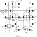
- Figure 2 is a schematic view of the structure of a hybrid power driving system for a vehicle according to a second embodiment of the present application.
- the main difference between the embodiment in Figure 2 and the embodiment in Figure 1 is that the gear box in Figure 1 has the fifth gear while the gear box in Figure 2 does not have the fifth gear.
- the reverse gear driven toothed gear is achieved by the driven toothed gear 24 of the first gear of the electric motor.
- the reverse gear driven toothed gear may also be achieved by the driven toothed gear 22 of the second gear of the electric motor.
- Figure 3 is a schematic view of the structure of a hybrid power driving system for a vehicle according to a third embodiment of the present application.
- the main difference between the embodiment in Figure 3 and the embodiment in Figure 1 is that the gear box in Figure 1 has two gears of the electric motor while the gear box in Figure 3 has just one gear of the electric motor; and the implementation mode of the first gear box part is different.
- a reverse middle toothed gear and the reverse gear driven toothed gear are achieved by an idle toothed gear 16 and the driven toothed gear 24 of the first gear of the electric motor.
- the driving toothed gear 30 of the first gear of the electric motor and the driven toothed gear 24 of the first gear of the electric motor are respectively fixedly connected toothed gears.
- one or both of the driving toothed gear 30 of the first gear of the electric motor and the driven toothed gear 24 of the first gear of the electric motor is nested toothed gear.
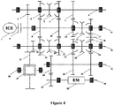
- Figure 4 is a schematic view of the structure of a hybrid power driving system for a vehicle according to a fourth embodiment of the present application.
- the main difference between the embodiment in Figure 4 and the embodiment in Figure 1 is that the implementation mode of the reverse gear of the first gear box part is different.
- the middle toothed gear of reverse gear and the reverse gear driven toothed gear are achieved by the idle toothed gear 16 and the driven toothed gear 24 of the first gear of the electric motor.
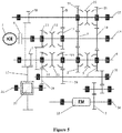
- Figure 5 is a schematic view of the structure of a hybrid power driving system for a vehicle according to a fifth embodiment of the present application.
- the main difference between the embodiment in Figure 5 and the embodiment in Figure 1 is that the arrangement order of all the gears of the gear box is different.
- the reverse gear driving toothed gear 13 referring to the axis of the input shaft 14, the reverse gear driving toothed gear 13, the third driving toothed gear 11, the first driving toothed gear 9 and the second driving toothed gear 10 are arranged in a listed sequence from a side towards the internal combustion engine 7 to a side away from the internal combustion engine 7.
- the axial positions of the driven toothed gears on the first intermediate shaft 6 and the second intermediate shaft 25 are varied accordingly.
- the second gear of the electric motor and the reverse gear driving toothed gear 13 have the same axial position, and the driving toothed gear 29 of the second gear of the electric motor forms the intermediate toothed gear, and the driven toothed gear 22 of the second gear of the electric motor forms the reverse gar driven toothed gear.
- the first gear and the third driving toothed gear 11 have the same axial position.
- the second gear box part includes the first intermediate shaft, and on the contrary, in the embodiments shown in Figures 1 to 4 , the second gear box part includes the second intermediate shaft.
- the axial positions of the first gear of the electric motor and the second gear of the electric motor may be interchanged, therefore the reverse gear driving toothed gear 13 and the first gear of the electric motor are combined, and the second gear of the electric motor and the third driving toothed gear 11 are located at the same axial position.
- the gear box according to the present application can operate in any one operating mode of the following operating modes:
- a hybrid power driving system and a hybrid power vehicle including the hybrid power driving system are provided.
- the hybrid power driving system includes an internal combustion engine 7, an electric motor 33 and a gear box.
- the gear box includes an input shaft 14, a first intermediate shaft 6, a second intermediate shaft 25, a third intermediate shaft 31 and an output shaft 26 which are arranged in parallel.
- the input shaft 14 is connected to the internal combustion engine 7 by a clutch 8.
- the driving toothed gear of the first gear and the third gear (the first driving toothed gear 9) and the driving toothed gear of the second gear and the fourth gear (the second driving toothed gear 10) are fixedly arranged in a listed sequence from a side of the input shaft 14 towards the internal combustion engine 7 to a side of the input shaft 14 away from the internal combustion engine 7.
- the first main reduction toothed gear 1, the driven toothed gear of the first gear (the first driven toothed gear 2), the first two-way synchronizer 3 and the driven toothed gear of the second gear (the second driven toothed gear 4) are arranged in a listed sequence from a side of the first intermediate shaft 16 towards the internal combustion engine 7 to a side of the first intermediate shaft 16 away from the internal combustion engine 7.
- the second main reduction toothed gear 18, the driven toothed gear of the third gear (the third driven toothed gear 19), the second two-way synchronizer 20, the driven toothed gear of the fourth gear (the fourth driven toothed gear 21) and the driven toothed gear 24 of the first gear of the electric motor are arranged in a listed sequence from a side of the second intermediate shaft 25 towards the internal combustion engine 7 to a side of the second intermediate shaft 25 away from the internal combustion engine 7.
- the third intermediate shaft 31 is connected to the electric motor 33 for transmission, and is provided with the driving toothed gear 30 of the first gear.
- the output shaft is provided with a differential 27, a differential toothed gear 17 of the differential 27 can engage with the first main reduction toothed gear 1 and the second main reduction toothed gear 18.
- gears using the internal combustion engine 7 as power source and one gear using the electric motor 33 as the power source are included, and the above description of the first gear, the second gear, the third gear, the four gear and the first gear of the electric motor are for distinguishing the gears, but not for limiting the specific structure of the gears.
- a power transmission path of the gears is specifically described as follows.
- the first gear of the internal combustion engine the first two-way synchronizer 3 on the first intermediate shaft 6 is actuated to engage with the driven toothed gear of the first gear sleeved on the first intermediate shaft 6, and the clutch 8 is closed.
- the power outputted by the internal combustion engine 7 passes through the input shaft 14, the driving toothed gear of the first gear and the third gear, the driven toothed gear of the first gear, the first intermediate shaft 6, the first main reduction toothed gear 1 and the differential toothed gear 17 in a listed sequence, and then is outputted via the differential 27 and finally via the output shaft 26.
- the second gear of the internal combustion engine the first two-way synchronizer 3 on the first intermediate shaft 6 is actuated to engage with the driven toothed gear of the second gear sleeved on the first intermediate shaft 6, the clutch 8 is closed, the power outputted by the internal combustion engine 7 passes through the input shaft 14, the driving toothed gear of the second gear and the fourth gear, the driven toothed gear of the second gear, the first intermediate shaft 6, the first main reduction toothed gear 1 and the differential toothed gear 17 in a listed sequence, and then is outputted via the differential 27 and finally via the output shaft 26.
- the third gear of the internal combustion engine the second two-way synchronizer 3 on the second intermediate shaft 25 is actuated to engage with the driven toothed gear 19 of the third gear sleeved on the second intermediate shaft 25, the clutch 8 is closed, the power outputted by the internal combustion engine 7 passes through the input shaft 14, the driving toothed gear of the first gear and the third gear, the driven toothed gear of the third gear, the second intermediate shaft 25, the second main reduction toothed gear 18 and the differential toothed gear 17 in a listed sequence, and then is outputted via the differential 27 and finally via the output shaft.
- the fourth gear of the internal combustion engine the second two-way synchronizer 3 on the second intermediate shaft 25 is actuated to engage with the driven toothed gear 19 of the third gear sleeved on the second intermediate shaft 25, the clutch 8 is closed, the power outputted by the internal combustion engine 7 passes through the input shaft 14, the driving toothed gear of the second gear and the fourth gear, the driven toothed gear of the fourth gear, the second intermediate shaft 25, the second main reduction toothed gear 18 and the differential toothed gear 17 in a listed sequence, and then is outputted via the differential 27 and finally via the output shaft 26.
- the power transmission path of the first gear of the electric motor passes through the third intermediate shaft 31, the driving toothed gear 30 of the first gear of the electric motor, the driven toothed gear 24 of the first gear of the electric motor, the second intermediate shaft 25, the second main reduction toothed gear 18 and the differential toothed gear 17 in a listed sequence, and then is outputted via the differential 27 and finally via the output shaft 26.
- the internal combustion engine 7 and the electric motor 33 are used as the hybrid power source, based on the power transmission path of the first gear of the electric motor, one of the power transmission routes of the first gear, the second gear, the third gear and the fourth gear is coupled, which can achieve the four hybrid power operating conditions of the advancing of the vehicle.
- the requirements of being driven simply by internal combustion engine, simply by the electric motor and by hybrid power can be satisfied.
- only one electric motor 33 is set as the electric power source, therefore the cost is low, and the over volume of the hybrid power driving system can be reduced in the case of meeting the requirements of the gears, and further the space occupied by the hybrid power driving system can be reduced, thus facilitating the mounting of the hybrid power driving system of the vehicle.
- the gears can be switched freely, and the power interruption problem during the gear switching process can be effectively avoided.
- the number of the gears is large, the driving efficiency of the internal combustion engine 7 and the electric motor 33 are high, the power match between the multiple gears is better, and thus the power performance and the fuel economy of the whole vehicle can be improved.
- the power transmission path of the reverse gear is the same as that of the first gear of the electric motor, just the electric motor is controlled to rotate reversely.
- the reverse gear function can be realized by the following two technical solutions.
- the first solution as shown in Figure 1 , the first synchronizer and the reverse gear driving toothed gear 13 are provided on the input shaft 14, the first synchronizer (a component of the two-way synchronizer 12 at the right side in Figure 1 ) can engage with the reverse gear driving toothed gear 13, and the reverse gear driving toothed gear 13 can engage with the driving toothed gear 30 of the first gear of the electric motor; and the reverse gear in this solution is that: the first synchronizer on the input shaft 14 is actuated to engage with the reverse gear driving toothed gear 13 sleeved on the input shaft 14, the power outputted by the internal combustion engine 7 passes through the input shaft 14, the reverse gear driving toothed gear 13, the driving toothed gear 30 of the first gear of the electric motor, the driven toothed gear 24 of the first gear of the electric motor, the second intermediate shaft 25, the second main reduction toothed gear 18 and the differential toothed gear 17 in a listed sequence, and then is outputted via the differential 27 and finally via the output shaft 26.
- the hybrid power driving system further includes a reverse gear idle toothed gear shaft 15 and an idle toothed gear 16 arranged on the reverse gear idle toothed gear shaft 15, and the first synchronizer (which is indicated by reference numeral 35 in Figure 2 ) and the reverse gear driving toothed gear 13 are provided on the input shaft 14, the idle toothed gear 16 engages with the reverse gear driving toothed gear 13 and the driven toothed gear 24 of the first gear of the electric motor respectively; and the reverse gear in this solution is that: the first synchronizer on the input shaft 14 is actuated to engage with the reverse gear driving toothed gear 13 sleeved on the input shaft 14, the power outputted by the internal combustion engine 7 passes through the input shaft 14, the reverse gear driving toothed gear 13, the idle toothed gear 16 arranged on the reverse gear idle toothed gear shaft 15, the driven toothed gear 24 of the first gear of the electric motor, the second intermediate shaft 25, the second main reduction toothed gear 18 and the differential toothed
- the power is transmitted from the reverse gear driving toothed gear 13 to the driven toothed gear 24 of the first gear of the electric motor and is further transmitted to the second intermediate shaft 25, thus achieving the reverse gear function.
- the reverse gear is achieved simply by engaging the reverse gear driving toothed gear 13 on the input shaft 14 with the driving toothed gear 30 of the first gear of the electric motor and further by engaging the driving toothed gear 30 of the first gear of the electric motor with the driven toothed gear 24 of the first gear of the electric motor.
- the overall structure is simple.
- the reverse gear idle toothed gear shaft 15 and the idle toothed gear 16 by arranging the reverse gear idle toothed gear shaft 15 and the idle toothed gear 16, the power transmission between the driving toothed gear 13 and the driven toothed gear 24 of the first gear of the electric motor is realized, and further the reverse gear of the vehicle is realized.
- the requirements on the arrangement space of the reverse gear driving toothed gear 13 and the driving toothed gear 30 of the first gear of the electric motor, that is, the relative space position of the input shaft 14 and the third intermediate shaft 31 is reduced.
- the reverse gear function in case of being driven by the internal combustion engine can be achieved by both of the first solution and the second solution, one of which can be specifically selected according to the needs.
- the power transmission path of the reverse gear purely by the internal combustion engine can be coupled to realize the hybrid condition of the reverse of the vehicle.
- the hybrid power driving system of the vehicle may include an idle charging operating mode, a driving charging operating mode and an internal combustion engine starting operating mode.
- the idle charging operating mode when the battery has a low electric quantity, the internal combustion engine 7 may provide power to the electric motor 33 and drives the electric motor 33 to charge the battery reversely; the first synchronizer on the input shaft 14 is actuated to engage with the reverse gear driving toothed gear 13, the clutch 8 is closed, the power outputted by the internal combustion engine 7 passes through the input shaft 14, the reverse gear driving toothed gear 13, the driving toothed gear 30 of the first gear of the electric motor (the power is transmitted from the reverse gear driving toothed gear 13 to the driving toothed gear 30 of the first gear of the electric motor directly or via the idle toothed gear 16 and the driven toothed gear 24 of the first gear of the electric motor), and the third intermediate shaft 31, and then finally is transmitted to the electric motor 33 to charge the battery thereof reversely.
- the driving charging operating mode during the driving process, when the battery has a low electric quantity, the internal combustion engine 7 may provide power to the electric motor 33 and drives the electric motor 33 to charge the battery reversely; and the driving charging in the hybrid power operating mode can be achieved by switching the gears.
- the first two-way synchronizer 3 on the first intermediate shaft 6 is actuated to engage with the driven toothed gear of the first gear sleeved on the first intermediate shaft 6, the clutch 8 is closed, the power outputted by the internal combustion engine 7 passes through the input shaft 14, the driving toothed gear of the first gear and the first gear, the driven toothed gear of the first gear, the first intermediate shaft 6, the first main reduction toothed gear 1 and the differential toothed gear 17 in a listed sequence.
- One part of the power is outputted via the differential 27 and finally via the output shaft 26; and the other part of the power outputted by the internal combustion engine 7 passes through the second main reduction toothed gear 18, the second intermediate shaft 25, the driven toothed gear 24 of the first gear of the electric motor, the driving toothed gear 30 of the first gear of the electric motor, and the third intermediate shaft 31, and finally is transmitted to the electric motor 33 to charge the battery thereof reversely.
- the operating mode of the electric motor 33 starting the internal combustion engine 7 when the vehicle is started or when the vehicle is switched from the operating mode of being driven simply by the electric motor to the hybrid power operating mode, the electric motor 33 can be used as the starting electric motor of the internal combustion engine 7. By switching the gears, the internal combustion engine 7 can be started by the gears of the electric motor 33 and the gears of the internal combustion engine 7.
- the first two-way synchronizer 3 on the first intermediate shaft 6 is actuated to engage with the driven toothed gear of the first gear sleeved on the first intermediate shaft 6, the clutch 8 is closed, the power outputted by the electric motor 33 passes through the third intermediate shaft 31, the driving toothed gear 30 of the first gear of the electric motor, the driven toothed gear 24 of the first gear of the electric motor, the second intermediate shaft 25, the second main reduction toothed gear 18 and the differential toothed gear 17 in a listed sequence.
- One part of the power is outputted via the differential 27 and finally via the output shaft 26; and the other part of the power outputted by the first main reduction toothed gear 1, the first intermediate shaft 6, the driven toothed gear of the first gear, the driving toothed gear of the first gear and the third gear, the input shaft 14 and the clutch, and finally is transmitted to the internal combustion engine 7 to start the same.
- the input shaft 14 may be provided with a driving toothed gear of a fifth gear (a third driving toothed gear 11).
- the intermediate shaft 6 or the second intermediate shaft 25 may be provided with a driven toothed gear of the fifth gear (a fifth driven toothed gear 5) fitted with the driving toothed gear of the fifth gear, that is to say, when the internal combustion engine 7 is used as the power source, there may be five gears, and in this case, the first synchronizer may be served as a component of a third two-way synchronizer 12, and the third two-way synchronizer 12 can engage with the driving toothed gear of the fifth gear or the reverse gear driving toothed gear 13 selectively.
- the first synchronizer may be a one-way synchronizer 35, which can engage with the reverse gear driving toothed gear 13.
- the driven toothed gear of the fifth gear is arranged on the first intermediate shaft 6 or the second intermediate shaft 25, and in this embodiment, as shown in Figures 1 , 3 and 4 , taking the case of the driven toothed gear of the fifth gear being arranged on the first intermediate shaft 6 as an example, the third two-way synchronizer 12 on the input shaft 14 is actuated to engage with the driving toothed gear of the fifth gear sleeved on the input shaft 14, the clutch 8 is closed, the power outputted by the internal combustion engine 7 passes through the input shaft 14, the driving toothed gear of the fifth gear, the driven toothed gear of the fifth gear, the first intermediate shaft 6, the first main reduction toothed gear 1 and the differential toothed gear 17 in a listed sequence, and then is outputted via the differential 27 and finally via the output shaft 26.
- the internal combustion engine 7 as the power source may include five gears; when the internal combustion engine 7 and the electric motor 33 serve as the hybrid power source, based on the power transmission path of the first gear of the electric motor, the power transmission path of one of the first gear to the fifth gear of the internal combustion engine is coupled, which may realize five operating modes of hybrid power of the advancing of the vehicle. Increased gears may achieve the power match of the internal combustion engine 7 and the electric motor 33 better, and thus the power performance and the fuel economy of the whole vehicle can be further improved.
- the driven toothed gear 24 of the first gear of the electric motor can be set in the following two manners.
- One is that the driven toothed gear 24 of the first gear of the electric motor is a fixedly connected toothed gear fixedly arranged on the second intermediate shaft 25; and the other is that the driven toothed gear 24 of the first gear of the electric motor is a nested toothed gear sleeved on the second intermediate shaft 25, which may further be provided with a second synchronizer fixedly connected to the nested toothed gear.
- the first setting manner can simplify the overall structure
- the second setting manner is flexible, and both of the setting manners can achieve the power transmission of the first gear of the electric motor.
- the third intermediate shaft 31 may further be provided with a driving toothed gear 29 of the second gear of the electric motor, and correspondingly, the second intermediate shaft 25 is provided with a driven toothed gear 22 of a second gear of the electric motor.
- the second synchronizer is a component of a fourth two-way synchronizer 23, which is located between the driven toothed gear 24 of the first gear of the electric motor and the driven toothed gear 22 of the second gear of the electric motor.
- pure electric driving includes two gears, as shown in figures 1 , 2 and 4 , the fourth two-way synchronizer 23 on the second intermediate shaft 25 is actuated to engage with the driven toothed gear 24 of the first gear of the electric motor sleeved on the second intermediate shaft 25, and the power transmission path is described above.
- the fourth two-way synchronizer 23 on the second intermediate shaft 25 is actuated to engage with the driven toothed gear 22 of the second gear of the electric motor sleeved on the second intermediate shaft 25, and the power outputted by the electric motor 33 passes through the third intermediate shaft 31, the driving toothed gear 29 of the second gear of the electric motor, a driven toothed gear 22 of the second gear of the electric motor, the second intermediate shaft 25, the second main reduction toothed gear 18 and the differential toothed gear 17, and then is outputted via the differential 17 and is finally outputted via the output shaft 26.
- the electric motor 33 as the power source may include two gears, when the internal combustion engine 7 and the electric motor 33 being as the hybrid power source, based on the power transmission path of the first gear of the electric motor and the power transmission path of the second gear of the electric motor, the power transmission path of the gears of the internal combustion engine are coupled, which may achieve eight (when the simply internal combustion engine driving has four gears) or ten (when the simply internal combustion engine driving has five gears) hybrid power transmission operating modes of the advancing of the vehicle. Increased gears may achieve the power match of the internal combustion engine 7 and the electric motor 33 better, and thus the power performance and the fuel economy of the whole vehicle can be further improved.
- the reverse gear in case of the pure electric motor driving, may also has the same power transmission path as the second gear of the electric motor, and just the electric motor 33 is controlled to rotate reversely. That is, two reverse gears in case of pure electric motor driving can both be coupled with the power transmission path of the reverse gear of the internal combustion engine to achieve the two hybrid power operating modes of the reverse of the vehicle.
- the driven toothed gear of the fifth gear may be arranged on the first intermediate shaft 6.
- the output shaft 26 and the differential toothed gear 17 or the output shaft gear is permanently connected. It is also possible that the differential toothed gear 17 or the output shaft gear constitutes as a nested gear and is fitted with a synchronizer.
- the internal combustion engine 7 drives the electric motor 33 via the differential toothed gear 17 or the output shaft gear to generate electricity, the synchronizer is disengaged, and the output shaft 26 is not driven by the internal combustion engine 7.
- the electric motor 33 drives the input shaft via the differential toothed gear 17 or the output shaft gear and thus starts the internal combustion engine 7, the synchronizer is disengaged, therefore the electric motor 33 may not undertake the task of driving the vehicle at the same time.
- the third intermediate shaft 31 is connected to the electric motor 33 for transmission, and specifically may be connected by gear or chain.
- the rotor shaft 34 of the electric motor 33 is provided with a first transmission toothed gear 32
- the third intermediate shaft 31 is provided with a second transmission toothed gear 28 fitted with the first transmission toothed gear 32
- the rotor shaft 34 of the electric motor 33 is connected to the third intermediate shaft 31 by gear engagement for transmission.
- the power of the electric motor 33 passes through the rotor shaft 34, the first transmission toothed gear 32 and the second transmission toothed gear 28 in a listed sequence, and then is transmitted to the third intermediate shaft 31.
- the electric motor 33 may be connected to the third intermediate shaft 31 via more transmission toothed gears for transmission.
- the rotor shaft 34 of the electric motor 33 is provided with a first driving chain wheel 38
- the third intermediate shaft is provided with a second driving chain wheel 37
- the transmission connection between the rotor shaft 34 of the electric motor 33 and the third intermediate shaft 31 are achieved by the first driving chain wheel 38 and the second driving chain wheel 37 connected by a chain.
- the power of the electric motor passes through the rotor shaft 34, the first driving chain wheel 38 and the second driving chain wheel 37, and is transmitted to the third intermediate shaft 34. While in the charging operating mode, the power is transmitted from the third intermediate shaft 31 to the electric motor reversely to charge the battery.
- Figure 7 is an abbreviated drawing of a hybrid drive gear combination according to an embodiment of the present application.
- the mark of ICE represents the internal combustion engine or the engine 7
- the mark of EM represents the electric motor 33.
- the internal combustion engine 7 may include five forward gears, i.e. the first gear to the fifth gear and one reverse gear
- the electric motor 33 may include two electric motor gears.
- Each connection line indicates a combination of one gear of the internal combustion engine and one gear of the electric motor.
- any one gear of the internal combustion engine can be combined with any one gear of the electric motor, thus there are ten hybrid driving modes and two hybrid reverse gear modes in total. It is an understood thing that any combination of other number of gears of the internal combustion engine and other number of gears of the electric motor can also be considered.
Landscapes
- Engineering & Computer Science (AREA)
- Mechanical Engineering (AREA)
- Chemical & Material Sciences (AREA)
- Combustion & Propulsion (AREA)
- Transportation (AREA)
- General Engineering & Computer Science (AREA)
- Hybrid Electric Vehicles (AREA)
- Structure Of Transmissions (AREA)
- Gear Transmission (AREA)
Applications Claiming Priority (2)
| Application Number | Priority Date | Filing Date | Title |
|---|---|---|---|
| CN201810327598 | 2018-04-12 | ||
| CN201910027640.4A CN110370916B (zh) | 2018-04-12 | 2019-01-11 | 混合动力车辆、混合动力驱动系统以及变速箱 |
Publications (3)
| Publication Number | Publication Date |
|---|---|
| EP3584101A2 true EP3584101A2 (de) | 2019-12-25 |
| EP3584101A3 EP3584101A3 (de) | 2021-08-11 |
| EP3584101B1 EP3584101B1 (de) | 2023-01-11 |
Family
ID=68248398
Family Applications (1)
| Application Number | Title | Priority Date | Filing Date |
|---|---|---|---|
| EP19179419.7A Active EP3584101B1 (de) | 2018-04-12 | 2019-06-11 | Hybridantriebsfahrzeug, hybridantriebsfahrsystem und getriebe |
Country Status (3)
| Country | Link |
|---|---|
| US (1) | US11364788B2 (de) |
| EP (1) | EP3584101B1 (de) |
| CN (1) | CN110370916B (de) |
Cited By (1)
| Publication number | Priority date | Publication date | Assignee | Title |
|---|---|---|---|---|
| EP3865329A1 (de) * | 2020-02-11 | 2021-08-18 | Getrag Ford Transmissions GmbH | Antriebsbaugruppe mit e-maschine für ein kraftfahrzeug |
Families Citing this family (3)
| Publication number | Priority date | Publication date | Assignee | Title |
|---|---|---|---|---|
| CN216555171U (zh) * | 2021-12-14 | 2022-05-17 | 全忠毅 | 一种变速器 |
| US12287027B2 (en) | 2023-06-07 | 2025-04-29 | Harley-Davidson Motor Company, Inc. | Reverse drive assembly for motorized vehicle |
| US12398786B2 (en) * | 2023-06-07 | 2025-08-26 | Harley-Davidson Motor Company, Inc. | Reverse drive system for a motorized vehicle |
Citations (2)
| Publication number | Priority date | Publication date | Assignee | Title |
|---|---|---|---|---|
| CN202283873U (zh) | 2011-09-30 | 2012-06-27 | 长城汽车股份有限公司 | 混合动力汽车传动系统 |
| CN107599818A (zh) | 2017-10-19 | 2018-01-19 | 上海汽车变速器有限公司 | 混合动力用双离合变速器 |
Family Cites Families (15)
| Publication number | Priority date | Publication date | Assignee | Title |
|---|---|---|---|---|
| EP1972481A1 (de) * | 2007-03-20 | 2008-09-24 | FEV Motorentechnik GmbH | Verfahren zum Betrieb eines Hybridantriebssystems sowie Hybridsantriebssystem mit zwei Teilgetrieben |
| CN102039807B (zh) * | 2009-10-13 | 2013-05-01 | 同济大学 | 一种三中间轴式车用有源传动装置 |
| JP2014054900A (ja) * | 2012-09-12 | 2014-03-27 | Aisin Ai Co Ltd | ハイブリッド車の動力伝達装置 |
| KR101611076B1 (ko) * | 2014-09-23 | 2016-04-11 | 현대자동차주식회사 | 차량의 하이브리드 변속기 |
| KR101551123B1 (ko) * | 2014-09-29 | 2015-09-07 | 현대자동차주식회사 | 하이브리드 차량용 파워트레인 |
| KR101637685B1 (ko) * | 2014-09-29 | 2016-07-08 | 현대자동차주식회사 | Amt 하이브리드 변속기 |
| CN105620460B (zh) * | 2014-11-18 | 2019-07-16 | 上海汽车集团股份有限公司 | 用于混合动力车辆变速器的控制系统和方法 |
| EP3061637A1 (de) * | 2015-02-27 | 2016-08-31 | AVL List GmbH | Mehrganggetriebe und Verfahren zum Betreiben eines Mehrganggetriebes |
| KR20160134967A (ko) * | 2015-05-14 | 2016-11-24 | 현대자동차주식회사 | 차량의 하이브리드 변속기 |
| JP2017214982A (ja) * | 2016-05-31 | 2017-12-07 | アイシン・エーアイ株式会社 | 動力伝達装置 |
| DE102016212605B4 (de) * | 2016-07-11 | 2024-02-15 | Zf Friedrichshafen Ag | Getriebe für ein Kraftfahrzeug |
| US20180015816A1 (en) * | 2016-07-12 | 2018-01-18 | GM Global Technology Operations LLC | Parallel-shaft transmission assembly with selectable electrification |
| CN109843623A (zh) * | 2016-08-08 | 2019-06-04 | 舍弗勒工程有限公司 | 用于机动车的动力总成系统以及操作动力总成系统的方法 |
| DE102016013477A1 (de) * | 2016-11-11 | 2017-05-18 | Daimler Ag | Hybriddoppelkupplungsgetriebe |
| DE102017220071A1 (de) * | 2017-11-10 | 2019-05-16 | Zf Friedrichshafen Ag | Getriebe für ein Kraftfahrzeug |
-
2019
- 2019-01-11 CN CN201910027640.4A patent/CN110370916B/zh active Active
- 2019-06-11 US US16/438,071 patent/US11364788B2/en active Active
- 2019-06-11 EP EP19179419.7A patent/EP3584101B1/de active Active
Patent Citations (2)
| Publication number | Priority date | Publication date | Assignee | Title |
|---|---|---|---|---|
| CN202283873U (zh) | 2011-09-30 | 2012-06-27 | 长城汽车股份有限公司 | 混合动力汽车传动系统 |
| CN107599818A (zh) | 2017-10-19 | 2018-01-19 | 上海汽车变速器有限公司 | 混合动力用双离合变速器 |
Cited By (1)
| Publication number | Priority date | Publication date | Assignee | Title |
|---|---|---|---|---|
| EP3865329A1 (de) * | 2020-02-11 | 2021-08-18 | Getrag Ford Transmissions GmbH | Antriebsbaugruppe mit e-maschine für ein kraftfahrzeug |
Also Published As
| Publication number | Publication date |
|---|---|
| EP3584101A3 (de) | 2021-08-11 |
| CN110370916A (zh) | 2019-10-25 |
| EP3584101B1 (de) | 2023-01-11 |
| CN110370916B (zh) | 2022-04-12 |
| US20200062105A1 (en) | 2020-02-27 |
| US11364788B2 (en) | 2022-06-21 |
Similar Documents
| Publication | Publication Date | Title |
|---|---|---|
| KR101481304B1 (ko) | Dct를 구비한 하이브리드 파워트레인 | |
| US11364788B2 (en) | Hybrid power vehicle, hybrid power driving system and gear box | |
| KR101500204B1 (ko) | 차량의 하이브리드 파워트레인 | |
| US9266418B2 (en) | Power transmission system of hybrid electric vehicle | |
| US20150005128A1 (en) | Power transmission system of hybrid electric vehicle | |
| US20150176682A1 (en) | Hybrid drive train for a motor vehicle | |
| US11293526B2 (en) | Hybrid dual-clutch transmission | |
| US9623744B2 (en) | Power transmission apparatus for vehicle | |
| US11273699B2 (en) | Power-driven system for vehicle and vehicle | |
| US10850599B2 (en) | Power-driven system for vehicle and vehicle | |
| JP2015157622A (ja) | ハイブリッド自動車用のドライブトレイン | |
| US9174523B2 (en) | Power transmission system of hybrid electric vehicle | |
| CN102490585A (zh) | 一种汽车混合动力总成 | |
| US11299041B2 (en) | Power-driven system for vehicle and vehicle | |
| US20150211607A1 (en) | Transmission for hybrid vehicle | |
| US20190202281A1 (en) | Power transmission apparatus for vehicle | |
| CN112166046A (zh) | 混合动力变速器和混合动力车辆 | |
| CN108944411A (zh) | 混合动力模块和车辆 | |
| CN108944412A (zh) | 用于车辆的混合动力模块 | |
| US10906522B2 (en) | Road vehicle with dual-clutch transmission and hybrid drive and relative control method | |
| KR101500205B1 (ko) | 차량의 하이브리드 파워트레인 | |
| CN103818231B (zh) | 变速器-发动机-组件 | |
| CN108638837A (zh) | 混合动力变速器、混合动力驱动系统和车辆 | |
| CN210161895U (zh) | 混合动力驱动系统及车辆 | |
| KR101592636B1 (ko) | 차량의 하이브리드 파워트레인 |
Legal Events
| Date | Code | Title | Description |
|---|---|---|---|
| PUAI | Public reference made under article 153(3) epc to a published international application that has entered the european phase |
Free format text: ORIGINAL CODE: 0009012 |
|
| STAA | Information on the status of an ep patent application or granted ep patent |
Free format text: STATUS: THE APPLICATION HAS BEEN PUBLISHED |
|
| AK | Designated contracting states |
Kind code of ref document: A2 Designated state(s): AL AT BE BG CH CY CZ DE DK EE ES FI FR GB GR HR HU IE IS IT LI LT LU LV MC MK MT NL NO PL PT RO RS SE SI SK SM TR |
|
| AX | Request for extension of the european patent |
Extension state: BA ME |
|
| RIN1 | Information on inventor provided before grant (corrected) |
Inventor name: FAN, YUCHUAN Inventor name: ZHU, JUN Inventor name: XU, BIN Inventor name: JIANG, DEYAN Inventor name: SUN, JUN Inventor name: ZHOU, JIAN Inventor name: GE, HAILONG Inventor name: GU, ZHENGMIN Inventor name: WANG, JIAN Inventor name: LIU, XINYU |
|
| PUAL | Search report despatched |
Free format text: ORIGINAL CODE: 0009013 |
|
| AK | Designated contracting states |
Kind code of ref document: A3 Designated state(s): AL AT BE BG CH CY CZ DE DK EE ES FI FR GB GR HR HU IE IS IT LI LT LU LV MC MK MT NL NO PL PT RO RS SE SI SK SM TR |
|
| RIC1 | Information provided on ipc code assigned before grant |
Ipc: B60K 6/547 20071001AFI20210706BHEP Ipc: B60K 6/36 20071001ALI20210706BHEP Ipc: F16H 3/093 20060101ALI20210706BHEP Ipc: B60K 6/48 20071001ALN20210706BHEP |
|
| STAA | Information on the status of an ep patent application or granted ep patent |
Free format text: STATUS: REQUEST FOR EXAMINATION WAS MADE |
|
| 17P | Request for examination filed |
Effective date: 20220128 |
|
| RBV | Designated contracting states (corrected) |
Designated state(s): AL AT BE BG CH CY CZ DE DK EE ES FI FR GB GR HR HU IE IS IT LI LT LU LV MC MK MT NL NO PL PT RO RS SE SI SK SM TR |
|
| GRAP | Despatch of communication of intention to grant a patent |
Free format text: ORIGINAL CODE: EPIDOSNIGR1 |
|
| STAA | Information on the status of an ep patent application or granted ep patent |
Free format text: STATUS: GRANT OF PATENT IS INTENDED |
|
| RIC1 | Information provided on ipc code assigned before grant |
Ipc: B60K 6/48 20071001ALN20220902BHEP Ipc: F16H 3/093 20060101ALI20220902BHEP Ipc: B60K 6/36 20071001ALI20220902BHEP Ipc: B60K 6/547 20071001AFI20220902BHEP |
|
| INTG | Intention to grant announced |
Effective date: 20220927 |
|
| GRAS | Grant fee paid |
Free format text: ORIGINAL CODE: EPIDOSNIGR3 |
|
| GRAA | (expected) grant |
Free format text: ORIGINAL CODE: 0009210 |
|
| STAA | Information on the status of an ep patent application or granted ep patent |
Free format text: STATUS: THE PATENT HAS BEEN GRANTED |
|
| AK | Designated contracting states |
Kind code of ref document: B1 Designated state(s): AL AT BE BG CH CY CZ DE DK EE ES FI FR GB GR HR HU IE IS IT LI LT LU LV MC MK MT NL NO PL PT RO RS SE SI SK SM TR |
|
| REG | Reference to a national code |
Ref country code: GB Ref legal event code: FG4D |
|
| REG | Reference to a national code |
Ref country code: CH Ref legal event code: EP |
|
| REG | Reference to a national code |
Ref country code: DE Ref legal event code: R096 Ref document number: 602019024197 Country of ref document: DE |
|
| REG | Reference to a national code |
Ref country code: IE Ref legal event code: FG4D |
|
| REG | Reference to a national code |
Ref country code: AT Ref legal event code: REF Ref document number: 1543218 Country of ref document: AT Kind code of ref document: T Effective date: 20230215 |
|
| REG | Reference to a national code |
Ref country code: LT Ref legal event code: MG9D |
|
| REG | Reference to a national code |
Ref country code: NL Ref legal event code: MP Effective date: 20230111 |
|
| REG | Reference to a national code |
Ref country code: AT Ref legal event code: MK05 Ref document number: 1543218 Country of ref document: AT Kind code of ref document: T Effective date: 20230111 |
|
| PG25 | Lapsed in a contracting state [announced via postgrant information from national office to epo] |
Ref country code: NL Free format text: LAPSE BECAUSE OF FAILURE TO SUBMIT A TRANSLATION OF THE DESCRIPTION OR TO PAY THE FEE WITHIN THE PRESCRIBED TIME-LIMIT Effective date: 20230111 |
|
| PG25 | Lapsed in a contracting state [announced via postgrant information from national office to epo] |
Ref country code: RS Free format text: LAPSE BECAUSE OF FAILURE TO SUBMIT A TRANSLATION OF THE DESCRIPTION OR TO PAY THE FEE WITHIN THE PRESCRIBED TIME-LIMIT Effective date: 20230111 Ref country code: PT Free format text: LAPSE BECAUSE OF FAILURE TO SUBMIT A TRANSLATION OF THE DESCRIPTION OR TO PAY THE FEE WITHIN THE PRESCRIBED TIME-LIMIT Effective date: 20230511 Ref country code: NO Free format text: LAPSE BECAUSE OF FAILURE TO SUBMIT A TRANSLATION OF THE DESCRIPTION OR TO PAY THE FEE WITHIN THE PRESCRIBED TIME-LIMIT Effective date: 20230411 Ref country code: LV Free format text: LAPSE BECAUSE OF FAILURE TO SUBMIT A TRANSLATION OF THE DESCRIPTION OR TO PAY THE FEE WITHIN THE PRESCRIBED TIME-LIMIT Effective date: 20230111 Ref country code: LT Free format text: LAPSE BECAUSE OF FAILURE TO SUBMIT A TRANSLATION OF THE DESCRIPTION OR TO PAY THE FEE WITHIN THE PRESCRIBED TIME-LIMIT Effective date: 20230111 Ref country code: HR Free format text: LAPSE BECAUSE OF FAILURE TO SUBMIT A TRANSLATION OF THE DESCRIPTION OR TO PAY THE FEE WITHIN THE PRESCRIBED TIME-LIMIT Effective date: 20230111 Ref country code: ES Free format text: LAPSE BECAUSE OF FAILURE TO SUBMIT A TRANSLATION OF THE DESCRIPTION OR TO PAY THE FEE WITHIN THE PRESCRIBED TIME-LIMIT Effective date: 20230111 Ref country code: AT Free format text: LAPSE BECAUSE OF FAILURE TO SUBMIT A TRANSLATION OF THE DESCRIPTION OR TO PAY THE FEE WITHIN THE PRESCRIBED TIME-LIMIT Effective date: 20230111 |
|
| PG25 | Lapsed in a contracting state [announced via postgrant information from national office to epo] |
Ref country code: SE Free format text: LAPSE BECAUSE OF FAILURE TO SUBMIT A TRANSLATION OF THE DESCRIPTION OR TO PAY THE FEE WITHIN THE PRESCRIBED TIME-LIMIT Effective date: 20230111 Ref country code: PL Free format text: LAPSE BECAUSE OF FAILURE TO SUBMIT A TRANSLATION OF THE DESCRIPTION OR TO PAY THE FEE WITHIN THE PRESCRIBED TIME-LIMIT Effective date: 20230111 Ref country code: IS Free format text: LAPSE BECAUSE OF FAILURE TO SUBMIT A TRANSLATION OF THE DESCRIPTION OR TO PAY THE FEE WITHIN THE PRESCRIBED TIME-LIMIT Effective date: 20230511 Ref country code: GR Free format text: LAPSE BECAUSE OF FAILURE TO SUBMIT A TRANSLATION OF THE DESCRIPTION OR TO PAY THE FEE WITHIN THE PRESCRIBED TIME-LIMIT Effective date: 20230412 Ref country code: FI Free format text: LAPSE BECAUSE OF FAILURE TO SUBMIT A TRANSLATION OF THE DESCRIPTION OR TO PAY THE FEE WITHIN THE PRESCRIBED TIME-LIMIT Effective date: 20230111 |
|
| REG | Reference to a national code |
Ref country code: DE Ref legal event code: R097 Ref document number: 602019024197 Country of ref document: DE |
|
| PG25 | Lapsed in a contracting state [announced via postgrant information from national office to epo] |
Ref country code: SM Free format text: LAPSE BECAUSE OF FAILURE TO SUBMIT A TRANSLATION OF THE DESCRIPTION OR TO PAY THE FEE WITHIN THE PRESCRIBED TIME-LIMIT Effective date: 20230111 Ref country code: RO Free format text: LAPSE BECAUSE OF FAILURE TO SUBMIT A TRANSLATION OF THE DESCRIPTION OR TO PAY THE FEE WITHIN THE PRESCRIBED TIME-LIMIT Effective date: 20230111 Ref country code: EE Free format text: LAPSE BECAUSE OF FAILURE TO SUBMIT A TRANSLATION OF THE DESCRIPTION OR TO PAY THE FEE WITHIN THE PRESCRIBED TIME-LIMIT Effective date: 20230111 Ref country code: DK Free format text: LAPSE BECAUSE OF FAILURE TO SUBMIT A TRANSLATION OF THE DESCRIPTION OR TO PAY THE FEE WITHIN THE PRESCRIBED TIME-LIMIT Effective date: 20230111 Ref country code: CZ Free format text: LAPSE BECAUSE OF FAILURE TO SUBMIT A TRANSLATION OF THE DESCRIPTION OR TO PAY THE FEE WITHIN THE PRESCRIBED TIME-LIMIT Effective date: 20230111 |
|
| PLBE | No opposition filed within time limit |
Free format text: ORIGINAL CODE: 0009261 |
|
| STAA | Information on the status of an ep patent application or granted ep patent |
Free format text: STATUS: NO OPPOSITION FILED WITHIN TIME LIMIT |
|
| PG25 | Lapsed in a contracting state [announced via postgrant information from national office to epo] |
Ref country code: SK Free format text: LAPSE BECAUSE OF FAILURE TO SUBMIT A TRANSLATION OF THE DESCRIPTION OR TO PAY THE FEE WITHIN THE PRESCRIBED TIME-LIMIT Effective date: 20230111 |
|
| 26N | No opposition filed |
Effective date: 20231012 |
|
| PG25 | Lapsed in a contracting state [announced via postgrant information from national office to epo] |
Ref country code: MC Free format text: LAPSE BECAUSE OF FAILURE TO SUBMIT A TRANSLATION OF THE DESCRIPTION OR TO PAY THE FEE WITHIN THE PRESCRIBED TIME-LIMIT Effective date: 20230111 |
|
| PG25 | Lapsed in a contracting state [announced via postgrant information from national office to epo] |
Ref country code: SI Free format text: LAPSE BECAUSE OF FAILURE TO SUBMIT A TRANSLATION OF THE DESCRIPTION OR TO PAY THE FEE WITHIN THE PRESCRIBED TIME-LIMIT Effective date: 20230111 Ref country code: MC Free format text: LAPSE BECAUSE OF FAILURE TO SUBMIT A TRANSLATION OF THE DESCRIPTION OR TO PAY THE FEE WITHIN THE PRESCRIBED TIME-LIMIT Effective date: 20230111 |
|
| REG | Reference to a national code |
Ref country code: CH Ref legal event code: PL |
|
| REG | Reference to a national code |
Ref country code: BE Ref legal event code: MM Effective date: 20230630 |
|
| PG25 | Lapsed in a contracting state [announced via postgrant information from national office to epo] |
Ref country code: LU Free format text: LAPSE BECAUSE OF NON-PAYMENT OF DUE FEES Effective date: 20230611 |
|
| REG | Reference to a national code |
Ref country code: IE Ref legal event code: MM4A |
|
| PG25 | Lapsed in a contracting state [announced via postgrant information from national office to epo] |
Ref country code: LU Free format text: LAPSE BECAUSE OF NON-PAYMENT OF DUE FEES Effective date: 20230611 |
|
| PG25 | Lapsed in a contracting state [announced via postgrant information from national office to epo] |
Ref country code: IE Free format text: LAPSE BECAUSE OF NON-PAYMENT OF DUE FEES Effective date: 20230611 |
|
| PG25 | Lapsed in a contracting state [announced via postgrant information from national office to epo] |
Ref country code: IE Free format text: LAPSE BECAUSE OF NON-PAYMENT OF DUE FEES Effective date: 20230611 Ref country code: CH Free format text: LAPSE BECAUSE OF NON-PAYMENT OF DUE FEES Effective date: 20230630 |
|
| PG25 | Lapsed in a contracting state [announced via postgrant information from national office to epo] |
Ref country code: IT Free format text: LAPSE BECAUSE OF FAILURE TO SUBMIT A TRANSLATION OF THE DESCRIPTION OR TO PAY THE FEE WITHIN THE PRESCRIBED TIME-LIMIT Effective date: 20230111 Ref country code: BE Free format text: LAPSE BECAUSE OF NON-PAYMENT OF DUE FEES Effective date: 20230630 |
|
| PG25 | Lapsed in a contracting state [announced via postgrant information from national office to epo] |
Ref country code: BG Free format text: LAPSE BECAUSE OF FAILURE TO SUBMIT A TRANSLATION OF THE DESCRIPTION OR TO PAY THE FEE WITHIN THE PRESCRIBED TIME-LIMIT Effective date: 20230111 |
|
| PG25 | Lapsed in a contracting state [announced via postgrant information from national office to epo] |
Ref country code: BG Free format text: LAPSE BECAUSE OF FAILURE TO SUBMIT A TRANSLATION OF THE DESCRIPTION OR TO PAY THE FEE WITHIN THE PRESCRIBED TIME-LIMIT Effective date: 20230111 |
|
| PGFP | Annual fee paid to national office [announced via postgrant information from national office to epo] |
Ref country code: DE Payment date: 20250618 Year of fee payment: 7 |
|
| PGFP | Annual fee paid to national office [announced via postgrant information from national office to epo] |
Ref country code: GB Payment date: 20250618 Year of fee payment: 7 |
|
| PGFP | Annual fee paid to national office [announced via postgrant information from national office to epo] |
Ref country code: FR Payment date: 20250626 Year of fee payment: 7 |
|
| PG25 | Lapsed in a contracting state [announced via postgrant information from national office to epo] |
Ref country code: CY Free format text: LAPSE BECAUSE OF FAILURE TO SUBMIT A TRANSLATION OF THE DESCRIPTION OR TO PAY THE FEE WITHIN THE PRESCRIBED TIME-LIMIT; INVALID AB INITIO Effective date: 20190611 |
|
| PG25 | Lapsed in a contracting state [announced via postgrant information from national office to epo] |
Ref country code: HU Free format text: LAPSE BECAUSE OF FAILURE TO SUBMIT A TRANSLATION OF THE DESCRIPTION OR TO PAY THE FEE WITHIN THE PRESCRIBED TIME-LIMIT; INVALID AB INITIO Effective date: 20190611 |
|
| PG25 | Lapsed in a contracting state [announced via postgrant information from national office to epo] |
Ref country code: TR Free format text: LAPSE BECAUSE OF FAILURE TO SUBMIT A TRANSLATION OF THE DESCRIPTION OR TO PAY THE FEE WITHIN THE PRESCRIBED TIME-LIMIT Effective date: 20230111 |