EP3584119A1 - Fahrzeugüberwachungsvorrichtung - Google Patents
Fahrzeugüberwachungsvorrichtung Download PDFInfo
- Publication number
- EP3584119A1 EP3584119A1 EP18754124.8A EP18754124A EP3584119A1 EP 3584119 A1 EP3584119 A1 EP 3584119A1 EP 18754124 A EP18754124 A EP 18754124A EP 3584119 A1 EP3584119 A1 EP 3584119A1
- Authority
- EP
- European Patent Office
- Prior art keywords
- vehicle
- image
- vehicle body
- monitoring device
- camera
- Prior art date
- Legal status (The legal status is an assumption and is not a legal conclusion. Google has not performed a legal analysis and makes no representation as to the accuracy of the status listed.)
- Granted
Links
Images


Classifications
-
- B—PERFORMING OPERATIONS; TRANSPORTING
- B60—VEHICLES IN GENERAL
- B60R—VEHICLES, VEHICLE FITTINGS, OR VEHICLE PARTS, NOT OTHERWISE PROVIDED FOR
- B60R1/00—Optical viewing arrangements; Real-time viewing arrangements for drivers or passengers using optical image capturing systems, e.g. cameras or video systems specially adapted for use in or on vehicles
- B60R1/02—Rear-view mirror arrangements
- B60R1/06—Rear-view mirror arrangements mounted on vehicle exterior
-
- B—PERFORMING OPERATIONS; TRANSPORTING
- B60—VEHICLES IN GENERAL
- B60R—VEHICLES, VEHICLE FITTINGS, OR VEHICLE PARTS, NOT OTHERWISE PROVIDED FOR
- B60R1/00—Optical viewing arrangements; Real-time viewing arrangements for drivers or passengers using optical image capturing systems, e.g. cameras or video systems specially adapted for use in or on vehicles
- B60R1/20—Real-time viewing arrangements for drivers or passengers using optical image capturing systems, e.g. cameras or video systems specially adapted for use in or on vehicles
- B60R1/22—Real-time viewing arrangements for drivers or passengers using optical image capturing systems, e.g. cameras or video systems specially adapted for use in or on vehicles for viewing an area outside the vehicle, e.g. the exterior of the vehicle
- B60R1/23—Real-time viewing arrangements for drivers or passengers using optical image capturing systems, e.g. cameras or video systems specially adapted for use in or on vehicles for viewing an area outside the vehicle, e.g. the exterior of the vehicle with a predetermined field of view
- B60R1/26—Real-time viewing arrangements for drivers or passengers using optical image capturing systems, e.g. cameras or video systems specially adapted for use in or on vehicles for viewing an area outside the vehicle, e.g. the exterior of the vehicle with a predetermined field of view to the rear of the vehicle
-
- B—PERFORMING OPERATIONS; TRANSPORTING
- B60—VEHICLES IN GENERAL
- B60J—WINDOWS, WINDSCREENS, NON-FIXED ROOFS, DOORS, OR SIMILAR DEVICES FOR VEHICLES; REMOVABLE EXTERNAL PROTECTIVE COVERINGS SPECIALLY ADAPTED FOR VEHICLES
- B60J5/00—Doors
- B60J5/04—Doors arranged at the vehicle sides
-
- B—PERFORMING OPERATIONS; TRANSPORTING
- B60—VEHICLES IN GENERAL
- B60R—VEHICLES, VEHICLE FITTINGS, OR VEHICLE PARTS, NOT OTHERWISE PROVIDED FOR
- B60R1/00—Optical viewing arrangements; Real-time viewing arrangements for drivers or passengers using optical image capturing systems, e.g. cameras or video systems specially adapted for use in or on vehicles
- B60R1/02—Rear-view mirror arrangements
- B60R1/04—Rear-view mirror arrangements mounted inside vehicle
-
- B—PERFORMING OPERATIONS; TRANSPORTING
- B60—VEHICLES IN GENERAL
- B60R—VEHICLES, VEHICLE FITTINGS, OR VEHICLE PARTS, NOT OTHERWISE PROVIDED FOR
- B60R1/00—Optical viewing arrangements; Real-time viewing arrangements for drivers or passengers using optical image capturing systems, e.g. cameras or video systems specially adapted for use in or on vehicles
- B60R1/02—Rear-view mirror arrangements
- B60R1/08—Rear-view mirror arrangements involving special optical features, e.g. avoiding blind spots, e.g. convex mirrors; Side-by-side associations of rear-view and other mirrors
-
- B—PERFORMING OPERATIONS; TRANSPORTING
- B60—VEHICLES IN GENERAL
- B60R—VEHICLES, VEHICLE FITTINGS, OR VEHICLE PARTS, NOT OTHERWISE PROVIDED FOR
- B60R11/00—Arrangements for holding or mounting articles, not otherwise provided for
- B60R11/04—Mounting of cameras operative during drive; Arrangement of controls thereof relative to the vehicle
-
- B—PERFORMING OPERATIONS; TRANSPORTING
- B60—VEHICLES IN GENERAL
- B60R—VEHICLES, VEHICLE FITTINGS, OR VEHICLE PARTS, NOT OTHERWISE PROVIDED FOR
- B60R16/00—Electric or fluid circuits specially adapted for vehicles and not otherwise provided for; Arrangement of elements of electric or fluid circuits specially adapted for vehicles and not otherwise provided for
- B60R16/02—Electric or fluid circuits specially adapted for vehicles and not otherwise provided for; Arrangement of elements of electric or fluid circuits specially adapted for vehicles and not otherwise provided for electric constitutive elements
-
- H—ELECTRICITY
- H04—ELECTRIC COMMUNICATION TECHNIQUE
- H04N—PICTORIAL COMMUNICATION, e.g. TELEVISION
- H04N23/00—Cameras or camera modules comprising electronic image sensors; Control thereof
-
- H—ELECTRICITY
- H04—ELECTRIC COMMUNICATION TECHNIQUE
- H04N—PICTORIAL COMMUNICATION, e.g. TELEVISION
- H04N23/00—Cameras or camera modules comprising electronic image sensors; Control thereof
- H04N23/60—Control of cameras or camera modules
-
- H—ELECTRICITY
- H04—ELECTRIC COMMUNICATION TECHNIQUE
- H04N—PICTORIAL COMMUNICATION, e.g. TELEVISION
- H04N7/00—Television systems
- H04N7/18—Closed-circuit television [CCTV] systems, i.e. systems in which the video signal is not broadcast
- H04N7/188—Capturing isolated or intermittent images triggered by the occurrence of a predetermined event, e.g. an object reaching a predetermined position
-
- B—PERFORMING OPERATIONS; TRANSPORTING
- B60—VEHICLES IN GENERAL
- B60R—VEHICLES, VEHICLE FITTINGS, OR VEHICLE PARTS, NOT OTHERWISE PROVIDED FOR
- B60R11/00—Arrangements for holding or mounting articles, not otherwise provided for
- B60R2011/0001—Arrangements for holding or mounting articles, not otherwise provided for characterised by position
- B60R2011/004—Arrangements for holding or mounting articles, not otherwise provided for characterised by position outside the vehicle
-
- B—PERFORMING OPERATIONS; TRANSPORTING
- B60—VEHICLES IN GENERAL
- B60R—VEHICLES, VEHICLE FITTINGS, OR VEHICLE PARTS, NOT OTHERWISE PROVIDED FOR
- B60R2300/00—Details of viewing arrangements using cameras and displays, specially adapted for use in a vehicle
- B60R2300/10—Details of viewing arrangements using cameras and displays, specially adapted for use in a vehicle characterised by the type of camera system used
- B60R2300/105—Details of viewing arrangements using cameras and displays, specially adapted for use in a vehicle characterised by the type of camera system used using multiple cameras
-
- B—PERFORMING OPERATIONS; TRANSPORTING
- B60—VEHICLES IN GENERAL
- B60R—VEHICLES, VEHICLE FITTINGS, OR VEHICLE PARTS, NOT OTHERWISE PROVIDED FOR
- B60R2300/00—Details of viewing arrangements using cameras and displays, specially adapted for use in a vehicle
- B60R2300/60—Details of viewing arrangements using cameras and displays, specially adapted for use in a vehicle characterised by monitoring and displaying vehicle exterior scenes from a transformed perspective
-
- B—PERFORMING OPERATIONS; TRANSPORTING
- B60—VEHICLES IN GENERAL
- B60R—VEHICLES, VEHICLE FITTINGS, OR VEHICLE PARTS, NOT OTHERWISE PROVIDED FOR
- B60R2300/00—Details of viewing arrangements using cameras and displays, specially adapted for use in a vehicle
- B60R2300/80—Details of viewing arrangements using cameras and displays, specially adapted for use in a vehicle characterised by the intended use of the viewing arrangement
- B60R2300/802—Details of viewing arrangements using cameras and displays, specially adapted for use in a vehicle characterised by the intended use of the viewing arrangement for monitoring and displaying vehicle exterior blind spot views
Definitions
- the invention relates to a vehicle monitoring device.
- a vehicle such as an automobile is provided with an outer mirror such as a door mirror.
- the outer mirror is used when a driver views a rear side and a diagonally backward of the vehicle, and is provided to protrude outward on the side surface of the vehicle body.
- an outer mirror causes an increase in air resistance when a vehicle travels, and since the shape and size of the mirror are limited, an area to be a blind spot is sometimes generated for the driver.
- Patent Document 1 discloses an electric mirror device in which an imaging means such as a camera instead of an outer mirror is mounted on a vehicle.
- an imaging means such as a camera instead of an outer mirror
- the rear side and the diagonally backward of the vehicle are captured by the imaging means, and the captured image is displayed on a monitor in a cabin.
- the angle of view (imaging range) of the imaging means is set to include the vehicle body side surface.
- Patent Document 2 discloses a camera mounted on an outside handle of a side door of a vehicle for the purpose of detecting an obstacle when the vehicle travels.
- the imaging range of the camera includes a vehicle body side surface of the vehicle and a rear side of the vehicle.
- abnormality occurring in a vehicle can be monitored by using an imaging means mounted on a vehicle body.
- the vehicle monitoring device in a vehicle monitoring device mounted on a vehicle including an imaging means that captures images of a vehicle body side surface, a rear side and a diagonally backward of the vehicle, the vehicle monitoring device includes a storage unit that stores a reference image defining a reference state of the vehicle body side surface appearing in the captured image of the imaging means, and an image comparison unit that detects an abnormal state of the vehicle body by comparing the captured images captured by the imaging means with the reference image read from the storage unit.
- the vehicle preferably includes an electric mirror device that presents to an occupant, the captured image of the rear side and the diagonally backward of the vehicle.
- the imaging means is preferably an imaging means for capturing an image of the rear side and the diagonally backward of the vehicle, in the electric mirror device.
- the imaging means is preferably attached to an outside handle disposed outside a side door of the vehicle.
- the image comparison unit preferably detects the abnormal state of the vehicle when the vehicle stops.
- the abnormality occurring in the vehicle would be appropriately monitored by using the captured image corresponding to the rear view of the vehicle.
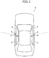
- Fig. 1 is an explanatory view showing the vehicle C.
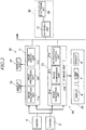
- Fig. 2 is a block diagram showing a system configuration of the vehicle C including the vehicle monitoring device 20 according to the embodiment.
- the vehicle C according to the embodiment is, for example, an automobile of a type having a pair of left and right front side doors 2, and a pair of left and right rear side doors 3.
- the vehicle C is equipped with an electric mirror device 10.
- the electric mirror device 10 is a device that performs rearview recognition by using a camera 5, instead of the outer mirror such as a door mirror.
- the electric mirror device 10 is mainly configured with a pair of left and right cameras 5 mounted on the vehicle C, an electronic mirror control unit 11, and a pair of display units 12 corresponding to the left and right cameras 5.
- the cameras 5 are respectively provided on left and right side surfaces of the vehicle body, and in the embodiment, the cameras 5 are mounted on outside handles 4 of the front side doors 2.
- Individual cameras 5 capture images of the rear view of the vehicle C, that is, a rear side and a diagonally backward of the vehicle C, including the vehicle body side surface, as shown by the range of broken lines of Fig. 1 (imaging means).
- the right camera 5 captures images of the rear side and a right diagonally backward of the vehicle C, including the right vehicle body side surface
- the left camera 5 captures images of the rear and a left diagonally backward of the vehicle C, including the left vehicle body side.
- a digital camera using an imaging element such as a CMOS and a CCD and a wide-angle lens is preferable.
- the electronic mirror control unit 11 is used to control the electric mirror device 10, and as a functional configuration, it includes an image acquisition unit 11a, an image processing unit 11b, and an image display unit 11c.
- a microcomputer which is mainly configured with a CPU, a ROM, a RAM, and an I/O interface would be used.
- the image acquisition unit 11a is connected to the left and right cameras 5, and acquires from the left and right cameras 5, captured images obtained by imaging the rear side and the diagonally backward of the vehicle C at a predetermined period.
- the image processing unit 11b cuts the captured image acquired by the image acquisition unit 11a according to a predetermined cutout range to generate a display image.
- the image processing unit 11b generates left and right display images corresponding to the left and right cameras 5.
- the image display unit 11c receives the display image from the image processing unit 11b, and displays the image on the pair of display units 12. At this time, the image processing unit 11b displays the display image processed from the right camera 5 on the display unit 12 corresponding to the right camera 5, and displays the display image processed from the left camera 5 on the display unit 12 corresponding to the left camera 5.
- a pair of display units 12 is, for example, an organic EL display, a liquid crystal display, or the like. Each display unit 12 is connected to the electronic mirror control unit 11.
- a pair of display units 12 is disposed, for example, on the base end portion of each front pillar located on both sides of the windshield, in the cabin.
- the display unit 12 corresponding to the right camera 5 is disposed at the base end portion of the front pillar on the right side, and the display unit 12 corresponding to the left camera 5 is disposed at the base end portion of the front pillar on the left side.
- the pair of display units 12 may be provided at other parts in the cabin such as an instrument panel.
- the vehicle C is equipped with the vehicle monitoring device 20.
- the vehicle monitoring device 20 is a device which monitors an abnormality occurring in the vehicle body side surface of the vehicle C. Abnormality monitored by the vehicle monitoring device 20 corresponds to, for example, a not-fully closed state of a door, a state of foreign matters being caught in the side doors 2 and 3, and an open state of the lid of the oil supply port.
- the vehicle monitoring device 20 is mainly configured with a monitoring control unit 21 and a notification unit 22.
- the vehicle monitoring device 20 is not constituted so as to be provided with a pair of left and right cameras independently, and is designed to utilize the left and right cameras 5 provided in the electric mirror device 10.
- the monitoring control unit 21 controls the electric mirror device 10, and as a functional configuration, it includes an image acquisition unit 21a, a storage unit 21b, an image comparison unit 21c, and a notification control unit 21d.
- an image acquisition unit 21a As the electronic mirror control unit 11, a microcomputer which is mainly configured with a CPU, a ROM, a RAM, and an I/O interface can be used.
- the image acquisition unit 21a is connected to the left and right cameras 5, and acquires from the left and right cameras 5, captured images obtained by capturing the rear and diagonally backward of the vehicle C.
- the storage unit 21b stores a reference image defining a reference state of a vehicle body side surface appearing in the captured image of the camera 5.
- the storage unit 21b stores a reference image corresponding to the right camera 5 and a reference image corresponding to the left camera 5, respectively.
- the image comparison unit 21c detects an abnormal state of the vehicle body by comparing the captured image actually captured by the camera 5 with the reference image read from the storage unit 21b. The abnormal state is determined with respect to the left and right vehicle body side surfaces.
- the image comparison unit 21c determines the abnormal state of the right side of the vehicle body by comparing the reference image corresponding to the right camera 5 with the captured image captured by the right camera 5. Further, the image comparison unit 21c determines the abnormal state of the left side of the vehicle body by comparing the reference image corresponding to the left camera 5 with the captured image captured by the left camera 5. Abnormality determined by the image comparison unit 21c is a not-fully closed state of a door, a state of foreign matters being caught in the side doors 2 and 3, and an open state of the lid of the oil supply port, and these abnormalities appear as a feature different from the reference image in the captured image actually captured by the camera 5. In a case where the image comparison unit 21c makes a determination as an abnormal state, the notification control unit 21d controls the notification unit 22 so as to perform notification.
- the notification unit 22 is configured to notify the occupant of the predetermined information.
- a display 6 for navigation provided in an instrument panel, an alarm lamp 7 in a meter device with a speed meter or the like disposed therein, or a speaker 8 can be used.
- the vehicle C is provided with a controller area network (CAN), and the electronic mirror control unit 11 of the electric mirror device 10 and the monitoring control unit 21 of the vehicle monitoring device 20 are connected to the CAN to communicate with each other. Further, the monitoring control unit 21 can communicate with the control unit of various sensors and various control systems mounted on the vehicle C through the CAN.
- CAN controller area network
- Such a control system includes a vehicle authentication system 30 for locking or unlocking the side doors 2 and 3 of the vehicle C and actuating an engine, called smart entry or passive entry.
- the vehicle authentication system 30 includes an on-vehicle unit 31 mounted on the vehicle C, and an electronic key 32 possessed by the user of the vehicle C. Since the on-vehicle unit 31 and the electronic key 32 perform authentication by radio communication, without performing a switch operation of the electronic key 32 or an operation by a mechanical key, the vehicle authentication system 30 executes locking or unlocking of the side doors 2 and 3 only in a series of operation process procedures of door opening and closing or activates an engine only by operating an engine switch installed in a vehicle. Further, the vehicle authentication system 30 can also lock or unlock the side doors 2 and 3 through the operation of a switch disposed in the electronic key 32.
- Fig. 3 is a flowchart showing a procedure of monitoring control by the vehicle monitoring device 20 according to the embodiment. The processing shown in this flowchart is executed by the monitoring control unit 21 with the turning-on of the ignition switch of the vehicle C as a trigger. When the ignition switch is turned on, the vehicle C is in a stop state.
- step 10 the image acquisition unit 21a acquires captured images from the left and right cameras 5, respectively.
- a vehicle body side surface of the vehicle C and the scenery of rear and rear side of the vehicle C is reflected on the captured images (left and right captured images) output from the left and right cameras 5.
- the left and right captured images acquired by the image acquisition unit 21a are output to the image comparison unit 21c.
- step 11 (S11) the image comparison unit 21c reads the reference image corresponding to the right camera 5 and the reference image corresponding to the left camera 5 from the storage unit 21b.
- step 12 (S12) the image comparison unit 21c determines the abnormal state of the right side of the vehicle body by comparing the reference image corresponding to the right camera 5 with the captured image acquired from the right camera 5. That is, the image comparison unit 21c compares the right vehicle body side surface (reference image) reflected in the state without abnormality with the right vehicle body side surface (actual captured image) actually imaged, and determines the abnormal state of the right side of the vehicle body from the difference.
- Abnormality determined by the image comparison unit 21c is a not-fully closed state of the front side door 2 or the rear side door 3, a state of foreign matters being caught in the side doors 2 and 3, and an open state of the lid of the oil supply port.
- the position of the front side door 2 is shifted outward as compared with a fully closed state, so the position of the camera 5 mounted on the outside handle 4 is also shifted outward.
- the position of the vehicle body side surface for example, the outer edge position of the vehicle body side surface
- the position of the vehicle body side surface reflected in the captured image is deviated as compared with that of the reference image.
- it is possible to determine whether the front side door 2 is not fully closed by determining the deviation between the outer edge position of the vehicle body side surface in the captured image and the outer edge position of the vehicle body side surface in the reference image, from the comparison between the captured image and the reference image.
- the position of the rear side door 3 is shifted outward as compared with a fully closed state.
- the position of the rear side door 3 (for example, the outer edge position of the rear side door 3) reflected in the captured image is deviated as compared with that in the reference image.
- it is possible to determine whether the rear side door 3 is not fully closed by determining the deviation between the outer edge position of the rear side door 3 in the captured image and the outer edge position of the rear side door 3 in the reference image, from the comparison between the captured image and the reference image.
- an open state of the lid of the oil supply port can be determined by determining the deviation between the outer edge position of the lid in the captured image and the outer edge position of the lid in the reference image, from the comparison between the captured image and the reference image.
- the image comparison unit 21c compares the reference image corresponding to the right camera 5 with the captured image obtained from the right camera 5, and in a case where a feature different from the reference image can be recognized, within the range of the vehicle body reflected in the captured image, it determines the abnormal state of the vehicle body.
- the image comparison unit 21c determines the abnormal state of the left side of the vehicle body by comparing the reference image corresponding to the left camera 5 with the captured image acquired from the left camera 5.
- step 13 the image comparison unit 21c determines whether or not there is abnormality in the vehicle body. In a case where there is an abnormality in the vehicle body, an affirmative determination is made in step 13, and the process proceeds to step 14 (S14). In a case where there is no abnormality in the vehicle body, a negative determination is made in step 13, and this routine is ended by skipping step 14.
- the notification control unit 21d controls the notification unit 22 so as to make a notification of an abnormal state of a vehicle body.
- Methods for notification include display of an abnormal state using the display 6 or the alarm lamp 7, audio output or alarm sound output using the speaker 8, and the like. As the contents of the notification, only the presence of abnormality may be notified, but the notification may be made in such a manner that the type of abnormality can be understood.
- the vehicle monitoring device 20 performs monitoring control by comparing the captured image captured by the camera 5 with the reference image to determine the abnormal state of the vehicle body of the vehicle C. Since the camera 5 for obtaining the rear view needs to project the rear side of the vehicle C, the vehicle body side surface of the vehicle C is included in the angle of view. Therefore, the abnormal state appearing in the vehicle body can be appropriately monitored by using the captured image of the camera 5.
- the camera 5 of the vehicle monitoring device 20 is shared with the camera 5 (imaging means) that captures an image of the rear and diagonally backward of the vehicle C in the electric mirror device 10.
- the vehicle monitoring device 20 can be constructed at a low cost.
- the angle of view of the camera 5 in the electric mirror device 10 is likely to be set in order to reduce the difference from the sense of use of the outer mirror in the related art. Therefore, the imaging range of the camera 5 is set so as to include the vehicle body side surface of the vehicle C. Thus, even if the camera 5 is shared, the vehicle monitoring device 20 can appropriately detect the abnormal state of the vehicle body.
- the electric mirror device 10 uses the captured image output from the camera 5 when the vehicle C travels, but the abnormality of the vehicle body to be determined by the vehicle monitoring device 20 occurs when an occupant gets on and off a vehicle, so the vehicle monitoring device 20 uses the captured image output from the camera 5 when the vehicle C stops. Therefore, the camera 5 can be used with different functions at the time of travel and at the time of stop, and the camera 5 and its captured image can be effectively utilized.
- the cameras 5 are attached to the outside handles 4 provided outside the side doors 2 and 3 of the vehicle C.
- the camera 5 can be disposed at a place where the rear view can be obtained.
- the rear view can be effectively obtained and the abnormality of the vehicle body can be appropriately monitored.
- monitoring control is performed when an ignition switch is turned on, on the assumption that an abnormal state when an occupant gets on a vehicle C is detected.
- the monitoring control may be performed when the occupant gets off the vehicle C.
- the vehicle monitoring device 20 may perform monitoring control when the side doors 2 and 3 are locked using a smart entry function of the vehicle authentication system 30, or the side doors 2 and 3 are locked using the electronic key 32 as a trigger.
- monitoring control may be performed, when the side doors 2 and 3 are operated from the open state to the closed state as a trigger.
- the monitoring control unit 21 can perform monitoring control in a period not overlapped with the operation period of the electric mirror device 10, for example, when the vehicle stops.
- the camera 5 can be used with different functions at the time of travel and at the time of stop, and the camera 5 and its captured image can be effectively utilized.
- the notification control unit 21d controls the notification unit 22 so as to make a notification of the abnormal state of the vehicle body.
- the occupant can be notified of the abnormal state of the vehicle body.
- the vehicle C starts traveling in a state where abnormality occurs in the vehicle body, or is separated from the vehicle C.
- the notification control unit 21d basically performs control so as to notify an occupant of the abnormal state, but in a case where the image comparison unit 21c determines the abnormal state of the vehicle body, the notification control unit 21d may perform a control other than notification as long as it performs a predetermined control.
- the notification control unit 21d may perform control to transmit a signal indicating an abnormal state to another control system (external equipment) mounted on the vehicle C.
- the control system receiving this signal can perform operations such as making a notification by using the notification unit provided in the system and deactivating the equipment that constitutes the system.
- Fig. 4 is a block diagram showing a configuration of the vehicle monitoring device 20 according to a second embodiment.
- the vehicle monitoring device 20 according to the second embodiment is different from the vehicle monitoring device 20 of the first embodiment in that it includes a function of updating a reference image.
- the description of the configuration overlapped with the first embodiment is omitted, and the difference will be mainly described.
- the monitoring control unit 21 of the vehicle monitoring device 20 includes a reference image update unit 21e, and the reference image stored in the storage unit 21b is updated as necessary by the reference image update unit 21e.
- Fig. 5 is a flowchart illustrating update processing of a reference image. The processing shown in the flowchart is executed by the monitoring control unit 21.
- step 20 the image acquisition unit 21a determines whether or not the side doors 2 and 3 are unlocked. In a case where the side doors 2 and 3 are unlocked, an affirmative determination is made in step 20, and the process proceeds to step 21 (S21). On the other hand, in a case where the side doors 2 and 3 are kept locked, the process returns to step 20.
- step 21 the image acquisition unit 21a acquires captured images from the left and right cameras 5, respectively.
- the scenery of rear and diagonally backward of the vehicle C, including the vehicle body side surface of the vehicle C, is reflected on the captured images (left and right captured images) output from the left and right cameras 5.
- the left and right captured images acquired by the image acquisition unit 21a are output to the reference image update unit 21e.
- the reference image update unit 21e updates the reference image stored in the storage unit 21b by using the left and right captured images acquired from the image acquisition unit 21a.
- the reference image for detecting the abnormality of the vehicle body.
- it can be reflected on the reference image.
- highly accurate monitoring control can be performed.
- the reference image is updated at a timing when the side doors 2 and 3 are unlocked. Unlocking the side doors 2 and 3 means that the side doors 2 and 3 are in a locked state, so there is a high probability that a situation such as a not-fully closed state of a door or a state of foreign matters being caught does not occur and the side doors 2 and 3 are properly closed. Therefore, the reference image can be updated in a proper state for the vehicle body, by updating the reference image, with unlocking timing as a trigger. As a result, highly accurate monitoring control can be performed.
- the camera is installed in the outside hand in the above-described embodiment, the camera may be installed in a place other than the outside handle.
Landscapes
- Engineering & Computer Science (AREA)
- Multimedia (AREA)
- Mechanical Engineering (AREA)
- Signal Processing (AREA)
- Closed-Circuit Television Systems (AREA)
- Rear-View Mirror Devices That Are Mounted On The Exterior Of The Vehicle (AREA)
- Studio Devices (AREA)
- Fittings On The Vehicle Exterior For Carrying Loads, And Devices For Holding Or Mounting Articles (AREA)
Applications Claiming Priority (2)
| Application Number | Priority Date | Filing Date | Title |
|---|---|---|---|
| JP2017028576A JP6807771B2 (ja) | 2017-02-20 | 2017-02-20 | 車両用監視装置 |
| PCT/JP2018/006073 WO2018151327A1 (ja) | 2017-02-20 | 2018-02-20 | 車両用監視装置 |
Publications (3)
| Publication Number | Publication Date |
|---|---|
| EP3584119A1 true EP3584119A1 (de) | 2019-12-25 |
| EP3584119A4 EP3584119A4 (de) | 2020-08-19 |
| EP3584119B1 EP3584119B1 (de) | 2021-10-13 |
Family
ID=63169401
Family Applications (1)
| Application Number | Title | Priority Date | Filing Date |
|---|---|---|---|
| EP18754124.8A Active EP3584119B1 (de) | 2017-02-20 | 2018-02-20 | Fahrzeugüberwachungsvorrichtung |
Country Status (5)
| Country | Link |
|---|---|
| US (1) | US11198392B2 (de) |
| EP (1) | EP3584119B1 (de) |
| JP (1) | JP6807771B2 (de) |
| CN (1) | CN110312640B (de) |
| WO (1) | WO2018151327A1 (de) |
Families Citing this family (4)
| Publication number | Priority date | Publication date | Assignee | Title |
|---|---|---|---|---|
| US11884215B2 (en) | 2019-05-15 | 2024-01-30 | Continental Automotive Systems, Inc. | Rear-view camera for pick-up trucks with open tailgates |
| JP2021167175A (ja) * | 2020-04-13 | 2021-10-21 | 株式会社デンソー | 車両用制御装置 |
| JP7380633B2 (ja) * | 2021-04-01 | 2023-11-15 | トヨタ自動車株式会社 | 監視装置、監視方法及び監視システム |
| WO2023108560A1 (zh) * | 2021-12-16 | 2023-06-22 | 华为技术有限公司 | 图像处理方法、装置、存储介质、电子后视镜系统和车辆 |
Family Cites Families (17)
| Publication number | Priority date | Publication date | Assignee | Title |
|---|---|---|---|---|
| US7366595B1 (en) * | 1999-06-25 | 2008-04-29 | Seiko Epson Corporation | Vehicle drive assist system |
| JP3599639B2 (ja) * | 2000-05-26 | 2004-12-08 | 松下電器産業株式会社 | 画像処理装置 |
| SE520075C2 (sv) * | 2000-12-01 | 2003-05-20 | Safenet I Harads Ab | Förfarande vid klämskyddsanordningar samt anordning för genomförande av förfarandet |
| US6947818B1 (en) * | 2004-09-20 | 2005-09-20 | Shih-Hsiung Li | Onboard monitoring device to ensure safe disembarkation of a transportation means |
| GB2418513A (en) * | 2004-09-22 | 2006-03-29 | Shih-Hsiung Li | A device for ensuring a safe exit from a vehicle |
| JP2006224873A (ja) | 2005-02-18 | 2006-08-31 | Denso Corp | 車両周辺監視装置 |
| JP5360491B2 (ja) * | 2009-11-13 | 2013-12-04 | アイシン精機株式会社 | 多機能カメラシステム |
| CN102343871B (zh) * | 2010-07-26 | 2013-10-30 | 浙江吉利汽车研究院有限公司 | 智能后视镜系统 |
| CN102087711A (zh) * | 2010-12-03 | 2011-06-08 | 黄晓峰 | 闭环的图像比较系统 |
| CN202279134U (zh) * | 2011-09-13 | 2012-06-20 | 北京华兴致远科技发展有限公司 | 一种列车故障检测系统 |
| JP6364797B2 (ja) * | 2014-02-06 | 2018-08-01 | 株式会社デンソー | 画像解析装置、および画像解析方法 |
| JP6206395B2 (ja) | 2014-12-26 | 2017-10-04 | トヨタ自動車株式会社 | 電子ミラー装置 |
| JP6567911B2 (ja) | 2015-07-24 | 2019-08-28 | 京セラ株式会社 | 音響発生器およびこれを備えた音響発生装置、電子機器 |
| CN105243782A (zh) * | 2015-10-23 | 2016-01-13 | 深圳市十方联智科技有限公司 | 车辆的监控方法和汽车、行车记录仪 |
| CN105915862A (zh) * | 2016-06-22 | 2016-08-31 | 成都嘉泽兴业科技有限责任公司 | 一种视频处理方法 |
| CN106203298A (zh) * | 2016-06-30 | 2016-12-07 | 北京集创北方科技股份有限公司 | 生物特征识别方法及装置 |
| CN109715423B (zh) | 2016-08-23 | 2022-12-09 | 株式会社阿尔发 | 车门外侧把手装置、车门及车辆 |
-
2017
- 2017-02-20 JP JP2017028576A patent/JP6807771B2/ja active Active
-
2018
- 2018-02-20 EP EP18754124.8A patent/EP3584119B1/de active Active
- 2018-02-20 CN CN201880012573.2A patent/CN110312640B/zh active Active
- 2018-02-20 WO PCT/JP2018/006073 patent/WO2018151327A1/ja not_active Ceased
-
2019
- 2019-08-14 US US16/540,894 patent/US11198392B2/en active Active
Also Published As
| Publication number | Publication date |
|---|---|
| US20190366927A1 (en) | 2019-12-05 |
| JP2018134885A (ja) | 2018-08-30 |
| JP6807771B2 (ja) | 2021-01-06 |
| WO2018151327A1 (ja) | 2018-08-23 |
| EP3584119B1 (de) | 2021-10-13 |
| EP3584119A4 (de) | 2020-08-19 |
| CN110312640A (zh) | 2019-10-08 |
| CN110312640B (zh) | 2023-06-02 |
| US11198392B2 (en) | 2021-12-14 |
Similar Documents
| Publication | Publication Date | Title |
|---|---|---|
| CN110300673B (zh) | 车辆外围监视装置 | |
| US11198392B2 (en) | Vehicle monitoring device | |
| CN107972609B (zh) | 用于门状态检测的方法和装置 | |
| US12497001B2 (en) | Information processing apparatus, program, computer readable recording medium, and information processing method | |
| US11498457B2 (en) | Vehicle mounted system, vehicle control system and method for monitoring an infant in a vehicle cabin | |
| EP3023943B1 (de) | Steuerung, steuerungsverfahren und computerlesbares aufzeichnungsmedium | |
| JP6515833B2 (ja) | 車両ドアロック制御装置 | |
| EP3248839B1 (de) | Fahrzeuganzeigevorrichtung | |
| JP7215228B2 (ja) | 制御装置、制御方法、制御プログラム | |
| US9956911B2 (en) | Object detection for vehicles | |
| US20180086268A1 (en) | Vehicle periphery imaging/display device and a computer-readable recording medium | |
| US20190329718A1 (en) | Electron mirror apparatus | |
| US12047668B2 (en) | Imaging assembly, and acquisition circuit mounted on a moving body | |
| CN110920517A (zh) | 检测机动车辆前部发动机罩的状态的方法和装置 | |
| JP6999761B2 (ja) | 車両用周辺監視装置 | |
| JP6500692B2 (ja) | 車両用防犯システム、車両用防犯方法 | |
| KR20250120198A (ko) | 점검 장치, 점검 방법 및 점검 프로그램 | |
| US20240303862A1 (en) | Camera calibration using a vehicle component location in field of view | |
| KR102829849B1 (ko) | 카메라 모니터링 시스템이 장착된 도어의 간섭회피 개방시스템 및 제어방법 | |
| JP2018069862A (ja) | 電子ミラー装置 | |
| JP2011111069A (ja) | 接近物検知装置、接近物検知システム、および、接近物検知方法 | |
| KR102291720B1 (ko) | 주행보조장치 | |
| JP2012086823A (ja) | 侵入検知装置及び車載制御装置 |
Legal Events
| Date | Code | Title | Description |
|---|---|---|---|
| STAA | Information on the status of an ep patent application or granted ep patent |
Free format text: STATUS: THE INTERNATIONAL PUBLICATION HAS BEEN MADE |
|
| PUAI | Public reference made under article 153(3) epc to a published international application that has entered the european phase |
Free format text: ORIGINAL CODE: 0009012 |
|
| STAA | Information on the status of an ep patent application or granted ep patent |
Free format text: STATUS: REQUEST FOR EXAMINATION WAS MADE |
|
| 17P | Request for examination filed |
Effective date: 20190820 |
|
| AK | Designated contracting states |
Kind code of ref document: A1 Designated state(s): AL AT BE BG CH CY CZ DE DK EE ES FI FR GB GR HR HU IE IS IT LI LT LU LV MC MK MT NL NO PL PT RO RS SE SI SK SM TR |
|
| AX | Request for extension of the european patent |
Extension state: BA ME |
|
| DAV | Request for validation of the european patent (deleted) | ||
| DAX | Request for extension of the european patent (deleted) | ||
| REG | Reference to a national code |
Ref country code: DE Ref legal event code: R079 Ref document number: 602018025034 Country of ref document: DE Free format text: PREVIOUS MAIN CLASS: B60R0001000000 Ipc: H04N0007180000 |
|
| A4 | Supplementary search report drawn up and despatched |
Effective date: 20200717 |
|
| RIC1 | Information provided on ipc code assigned before grant |
Ipc: B60R 1/04 20060101ALI20200713BHEP Ipc: H04N 5/232 20060101ALI20200713BHEP Ipc: B60R 1/08 20060101ALI20200713BHEP Ipc: B60R 1/00 20060101ALI20200713BHEP Ipc: B60R 16/02 20060101ALI20200713BHEP Ipc: B60R 1/06 20060101ALI20200713BHEP Ipc: B60J 5/04 20060101ALI20200713BHEP Ipc: H04N 7/18 20060101AFI20200713BHEP |
|
| GRAP | Despatch of communication of intention to grant a patent |
Free format text: ORIGINAL CODE: EPIDOSNIGR1 |
|
| STAA | Information on the status of an ep patent application or granted ep patent |
Free format text: STATUS: GRANT OF PATENT IS INTENDED |
|
| INTG | Intention to grant announced |
Effective date: 20210507 |
|
| RIN1 | Information on inventor provided before grant (corrected) |
Inventor name: KATO, TERUHISA Inventor name: SAITO, SOH Inventor name: KANIWA, KAZUHIKO Inventor name: SAKAKURA, HIROAKI |
|
| GRAS | Grant fee paid |
Free format text: ORIGINAL CODE: EPIDOSNIGR3 |
|
| GRAA | (expected) grant |
Free format text: ORIGINAL CODE: 0009210 |
|
| STAA | Information on the status of an ep patent application or granted ep patent |
Free format text: STATUS: THE PATENT HAS BEEN GRANTED |
|
| AK | Designated contracting states |
Kind code of ref document: B1 Designated state(s): AL AT BE BG CH CY CZ DE DK EE ES FI FR GB GR HR HU IE IS IT LI LT LU LV MC MK MT NL NO PL PT RO RS SE SI SK SM TR |
|
| REG | Reference to a national code |
Ref country code: GB Ref legal event code: FG4D |
|
| REG | Reference to a national code |
Ref country code: CH Ref legal event code: EP |
|
| REG | Reference to a national code |
Ref country code: DE Ref legal event code: R096 Ref document number: 602018025034 Country of ref document: DE |
|
| REG | Reference to a national code |
Ref country code: IE Ref legal event code: FG4D |
|
| REG | Reference to a national code |
Ref country code: AT Ref legal event code: REF Ref document number: 1439020 Country of ref document: AT Kind code of ref document: T Effective date: 20211115 |
|
| REG | Reference to a national code |
Ref country code: LT Ref legal event code: MG9D |
|
| REG | Reference to a national code |
Ref country code: NL Ref legal event code: MP Effective date: 20211013 |
|
| REG | Reference to a national code |
Ref country code: AT Ref legal event code: MK05 Ref document number: 1439020 Country of ref document: AT Kind code of ref document: T Effective date: 20211013 |
|
| PG25 | Lapsed in a contracting state [announced via postgrant information from national office to epo] |
Ref country code: RS Free format text: LAPSE BECAUSE OF FAILURE TO SUBMIT A TRANSLATION OF THE DESCRIPTION OR TO PAY THE FEE WITHIN THE PRESCRIBED TIME-LIMIT Effective date: 20211013 Ref country code: LT Free format text: LAPSE BECAUSE OF FAILURE TO SUBMIT A TRANSLATION OF THE DESCRIPTION OR TO PAY THE FEE WITHIN THE PRESCRIBED TIME-LIMIT Effective date: 20211013 Ref country code: FI Free format text: LAPSE BECAUSE OF FAILURE TO SUBMIT A TRANSLATION OF THE DESCRIPTION OR TO PAY THE FEE WITHIN THE PRESCRIBED TIME-LIMIT Effective date: 20211013 Ref country code: BG Free format text: LAPSE BECAUSE OF FAILURE TO SUBMIT A TRANSLATION OF THE DESCRIPTION OR TO PAY THE FEE WITHIN THE PRESCRIBED TIME-LIMIT Effective date: 20220113 Ref country code: AT Free format text: LAPSE BECAUSE OF FAILURE TO SUBMIT A TRANSLATION OF THE DESCRIPTION OR TO PAY THE FEE WITHIN THE PRESCRIBED TIME-LIMIT Effective date: 20211013 |
|
| PG25 | Lapsed in a contracting state [announced via postgrant information from national office to epo] |
Ref country code: IS Free format text: LAPSE BECAUSE OF FAILURE TO SUBMIT A TRANSLATION OF THE DESCRIPTION OR TO PAY THE FEE WITHIN THE PRESCRIBED TIME-LIMIT Effective date: 20220213 Ref country code: SE Free format text: LAPSE BECAUSE OF FAILURE TO SUBMIT A TRANSLATION OF THE DESCRIPTION OR TO PAY THE FEE WITHIN THE PRESCRIBED TIME-LIMIT Effective date: 20211013 Ref country code: PT Free format text: LAPSE BECAUSE OF FAILURE TO SUBMIT A TRANSLATION OF THE DESCRIPTION OR TO PAY THE FEE WITHIN THE PRESCRIBED TIME-LIMIT Effective date: 20220214 Ref country code: PL Free format text: LAPSE BECAUSE OF FAILURE TO SUBMIT A TRANSLATION OF THE DESCRIPTION OR TO PAY THE FEE WITHIN THE PRESCRIBED TIME-LIMIT Effective date: 20211013 Ref country code: NO Free format text: LAPSE BECAUSE OF FAILURE TO SUBMIT A TRANSLATION OF THE DESCRIPTION OR TO PAY THE FEE WITHIN THE PRESCRIBED TIME-LIMIT Effective date: 20220113 Ref country code: NL Free format text: LAPSE BECAUSE OF FAILURE TO SUBMIT A TRANSLATION OF THE DESCRIPTION OR TO PAY THE FEE WITHIN THE PRESCRIBED TIME-LIMIT Effective date: 20211013 Ref country code: LV Free format text: LAPSE BECAUSE OF FAILURE TO SUBMIT A TRANSLATION OF THE DESCRIPTION OR TO PAY THE FEE WITHIN THE PRESCRIBED TIME-LIMIT Effective date: 20211013 Ref country code: HR Free format text: LAPSE BECAUSE OF FAILURE TO SUBMIT A TRANSLATION OF THE DESCRIPTION OR TO PAY THE FEE WITHIN THE PRESCRIBED TIME-LIMIT Effective date: 20211013 Ref country code: GR Free format text: LAPSE BECAUSE OF FAILURE TO SUBMIT A TRANSLATION OF THE DESCRIPTION OR TO PAY THE FEE WITHIN THE PRESCRIBED TIME-LIMIT Effective date: 20220114 Ref country code: ES Free format text: LAPSE BECAUSE OF FAILURE TO SUBMIT A TRANSLATION OF THE DESCRIPTION OR TO PAY THE FEE WITHIN THE PRESCRIBED TIME-LIMIT Effective date: 20211013 |
|
| REG | Reference to a national code |
Ref country code: DE Ref legal event code: R097 Ref document number: 602018025034 Country of ref document: DE |
|
| PG25 | Lapsed in a contracting state [announced via postgrant information from national office to epo] |
Ref country code: SM Free format text: LAPSE BECAUSE OF FAILURE TO SUBMIT A TRANSLATION OF THE DESCRIPTION OR TO PAY THE FEE WITHIN THE PRESCRIBED TIME-LIMIT Effective date: 20211013 Ref country code: SK Free format text: LAPSE BECAUSE OF FAILURE TO SUBMIT A TRANSLATION OF THE DESCRIPTION OR TO PAY THE FEE WITHIN THE PRESCRIBED TIME-LIMIT Effective date: 20211013 Ref country code: RO Free format text: LAPSE BECAUSE OF FAILURE TO SUBMIT A TRANSLATION OF THE DESCRIPTION OR TO PAY THE FEE WITHIN THE PRESCRIBED TIME-LIMIT Effective date: 20211013 Ref country code: EE Free format text: LAPSE BECAUSE OF FAILURE TO SUBMIT A TRANSLATION OF THE DESCRIPTION OR TO PAY THE FEE WITHIN THE PRESCRIBED TIME-LIMIT Effective date: 20211013 Ref country code: DK Free format text: LAPSE BECAUSE OF FAILURE TO SUBMIT A TRANSLATION OF THE DESCRIPTION OR TO PAY THE FEE WITHIN THE PRESCRIBED TIME-LIMIT Effective date: 20211013 Ref country code: CZ Free format text: LAPSE BECAUSE OF FAILURE TO SUBMIT A TRANSLATION OF THE DESCRIPTION OR TO PAY THE FEE WITHIN THE PRESCRIBED TIME-LIMIT Effective date: 20211013 |
|
| PLBE | No opposition filed within time limit |
Free format text: ORIGINAL CODE: 0009261 |
|
| STAA | Information on the status of an ep patent application or granted ep patent |
Free format text: STATUS: NO OPPOSITION FILED WITHIN TIME LIMIT |
|
| 26N | No opposition filed |
Effective date: 20220714 |
|
| PG25 | Lapsed in a contracting state [announced via postgrant information from national office to epo] |
Ref country code: MC Free format text: LAPSE BECAUSE OF FAILURE TO SUBMIT A TRANSLATION OF THE DESCRIPTION OR TO PAY THE FEE WITHIN THE PRESCRIBED TIME-LIMIT Effective date: 20211013 |
|
| REG | Reference to a national code |
Ref country code: CH Ref legal event code: PL |
|
| REG | Reference to a national code |
Ref country code: BE Ref legal event code: MM Effective date: 20220228 |
|
| PG25 | Lapsed in a contracting state [announced via postgrant information from national office to epo] |
Ref country code: LU Free format text: LAPSE BECAUSE OF NON-PAYMENT OF DUE FEES Effective date: 20220220 Ref country code: AL Free format text: LAPSE BECAUSE OF FAILURE TO SUBMIT A TRANSLATION OF THE DESCRIPTION OR TO PAY THE FEE WITHIN THE PRESCRIBED TIME-LIMIT Effective date: 20211013 |
|
| PG25 | Lapsed in a contracting state [announced via postgrant information from national office to epo] |
Ref country code: SI Free format text: LAPSE BECAUSE OF FAILURE TO SUBMIT A TRANSLATION OF THE DESCRIPTION OR TO PAY THE FEE WITHIN THE PRESCRIBED TIME-LIMIT Effective date: 20211013 |
|
| PG25 | Lapsed in a contracting state [announced via postgrant information from national office to epo] |
Ref country code: LI Free format text: LAPSE BECAUSE OF NON-PAYMENT OF DUE FEES Effective date: 20220228 Ref country code: IE Free format text: LAPSE BECAUSE OF NON-PAYMENT OF DUE FEES Effective date: 20220220 Ref country code: CH Free format text: LAPSE BECAUSE OF NON-PAYMENT OF DUE FEES Effective date: 20220228 |
|
| PG25 | Lapsed in a contracting state [announced via postgrant information from national office to epo] |
Ref country code: BE Free format text: LAPSE BECAUSE OF NON-PAYMENT OF DUE FEES Effective date: 20220228 |
|
| PG25 | Lapsed in a contracting state [announced via postgrant information from national office to epo] |
Ref country code: IT Free format text: LAPSE BECAUSE OF FAILURE TO SUBMIT A TRANSLATION OF THE DESCRIPTION OR TO PAY THE FEE WITHIN THE PRESCRIBED TIME-LIMIT Effective date: 20211013 |
|
| PG25 | Lapsed in a contracting state [announced via postgrant information from national office to epo] |
Ref country code: MK Free format text: LAPSE BECAUSE OF FAILURE TO SUBMIT A TRANSLATION OF THE DESCRIPTION OR TO PAY THE FEE WITHIN THE PRESCRIBED TIME-LIMIT Effective date: 20211013 Ref country code: CY Free format text: LAPSE BECAUSE OF FAILURE TO SUBMIT A TRANSLATION OF THE DESCRIPTION OR TO PAY THE FEE WITHIN THE PRESCRIBED TIME-LIMIT Effective date: 20211013 |
|
| PG25 | Lapsed in a contracting state [announced via postgrant information from national office to epo] |
Ref country code: HU Free format text: LAPSE BECAUSE OF FAILURE TO SUBMIT A TRANSLATION OF THE DESCRIPTION OR TO PAY THE FEE WITHIN THE PRESCRIBED TIME-LIMIT; INVALID AB INITIO Effective date: 20180220 |
|
| PG25 | Lapsed in a contracting state [announced via postgrant information from national office to epo] |
Ref country code: MT Free format text: LAPSE BECAUSE OF FAILURE TO SUBMIT A TRANSLATION OF THE DESCRIPTION OR TO PAY THE FEE WITHIN THE PRESCRIBED TIME-LIMIT Effective date: 20211013 |
|
| PGFP | Annual fee paid to national office [announced via postgrant information from national office to epo] |
Ref country code: FR Payment date: 20241231 Year of fee payment: 8 |
|
| PGFP | Annual fee paid to national office [announced via postgrant information from national office to epo] |
Ref country code: DE Payment date: 20241231 Year of fee payment: 8 |
|
| PGFP | Annual fee paid to national office [announced via postgrant information from national office to epo] |
Ref country code: GB Payment date: 20250102 Year of fee payment: 8 |
|
| PG25 | Lapsed in a contracting state [announced via postgrant information from national office to epo] |
Ref country code: TR Free format text: LAPSE BECAUSE OF FAILURE TO SUBMIT A TRANSLATION OF THE DESCRIPTION OR TO PAY THE FEE WITHIN THE PRESCRIBED TIME-LIMIT Effective date: 20211013 |