EP3584197A1 - Système de stockage - Google Patents
Système de stockage Download PDFInfo
- Publication number
- EP3584197A1 EP3584197A1 EP19184795.3A EP19184795A EP3584197A1 EP 3584197 A1 EP3584197 A1 EP 3584197A1 EP 19184795 A EP19184795 A EP 19184795A EP 3584197 A1 EP3584197 A1 EP 3584197A1
- Authority
- EP
- European Patent Office
- Prior art keywords
- piece goods
- storage
- receiving device
- transport
- storage channel
- Prior art date
- Legal status (The legal status is an assumption and is not a legal conclusion. Google has not performed a legal analysis and makes no representation as to the accuracy of the status listed.)
- Granted
Links
Images







Classifications
-
- B—PERFORMING OPERATIONS; TRANSPORTING
- B65—CONVEYING; PACKING; STORING; HANDLING THIN OR FILAMENTARY MATERIAL
- B65G—TRANSPORT OR STORAGE DEVICES, e.g. CONVEYORS FOR LOADING OR TIPPING, SHOP CONVEYOR SYSTEMS OR PNEUMATIC TUBE CONVEYORS
- B65G1/00—Storing articles, individually or in orderly arrangement, in warehouses or magazines
- B65G1/02—Storage devices
- B65G1/04—Storage devices mechanical
- B65G1/0407—Storage devices mechanical using stacker cranes
- B65G1/0435—Storage devices mechanical using stacker cranes with pulling or pushing means on either stacking crane or stacking area
-
- B—PERFORMING OPERATIONS; TRANSPORTING
- B65—CONVEYING; PACKING; STORING; HANDLING THIN OR FILAMENTARY MATERIAL
- B65G—TRANSPORT OR STORAGE DEVICES, e.g. CONVEYORS FOR LOADING OR TIPPING, SHOP CONVEYOR SYSTEMS OR PNEUMATIC TUBE CONVEYORS
- B65G1/00—Storing articles, individually or in orderly arrangement, in warehouses or magazines
- B65G1/02—Storage devices
- B65G1/04—Storage devices mechanical
- B65G1/0407—Storage devices mechanical using stacker cranes
-
- B—PERFORMING OPERATIONS; TRANSPORTING
- B65—CONVEYING; PACKING; STORING; HANDLING THIN OR FILAMENTARY MATERIAL
- B65G—TRANSPORT OR STORAGE DEVICES, e.g. CONVEYORS FOR LOADING OR TIPPING, SHOP CONVEYOR SYSTEMS OR PNEUMATIC TUBE CONVEYORS
- B65G1/00—Storing articles, individually or in orderly arrangement, in warehouses or magazines
- B65G1/02—Storage devices
- B65G1/04—Storage devices mechanical
- B65G1/0407—Storage devices mechanical using stacker cranes
- B65G1/0421—Storage devices mechanical using stacker cranes with control for stacker crane operations
-
- B—PERFORMING OPERATIONS; TRANSPORTING
- B65—CONVEYING; PACKING; STORING; HANDLING THIN OR FILAMENTARY MATERIAL
- B65G—TRANSPORT OR STORAGE DEVICES, e.g. CONVEYORS FOR LOADING OR TIPPING, SHOP CONVEYOR SYSTEMS OR PNEUMATIC TUBE CONVEYORS
- B65G1/00—Storing articles, individually or in orderly arrangement, in warehouses or magazines
- B65G1/02—Storage devices
- B65G1/04—Storage devices mechanical
- B65G1/0485—Check-in, check-out devices
-
- B—PERFORMING OPERATIONS; TRANSPORTING
- B65—CONVEYING; PACKING; STORING; HANDLING THIN OR FILAMENTARY MATERIAL
- B65G—TRANSPORT OR STORAGE DEVICES, e.g. CONVEYORS FOR LOADING OR TIPPING, SHOP CONVEYOR SYSTEMS OR PNEUMATIC TUBE CONVEYORS
- B65G1/00—Storing articles, individually or in orderly arrangement, in warehouses or magazines
- B65G1/02—Storage devices
- B65G1/04—Storage devices mechanical
- B65G1/137—Storage devices mechanical with arrangements or automatic control means for selecting which articles are to be removed
-
- B—PERFORMING OPERATIONS; TRANSPORTING
- B65—CONVEYING; PACKING; STORING; HANDLING THIN OR FILAMENTARY MATERIAL
- B65G—TRANSPORT OR STORAGE DEVICES, e.g. CONVEYORS FOR LOADING OR TIPPING, SHOP CONVEYOR SYSTEMS OR PNEUMATIC TUBE CONVEYORS
- B65G1/00—Storing articles, individually or in orderly arrangement, in warehouses or magazines
- B65G1/02—Storage devices
- B65G1/04—Storage devices mechanical
- B65G1/137—Storage devices mechanical with arrangements or automatic control means for selecting which articles are to be removed
- B65G1/1371—Storage devices mechanical with arrangements or automatic control means for selecting which articles are to be removed with data records
Definitions
- the EP 2 234 904 A1 discloses a method for storing loading aids with a transport device in a storage channel with storage spaces arranged one behind the other for piece goods of uniform length and width dimensions.
- a first piece of goods is conveyed from the transport device into the storage channel to the front storage place in the storage direction.
- a second piece of goods is moved from the transport device into the storage channel to the front storage location and the first piece of goods is moved in the direction of storage to the storage area behind and the second piece of goods is conveyed to the front storage area so that the items are stored close to each other in the storage channel.
- the transport device has entrainment elements for the storage process and transport elements for the retrieval process.
- a transport device for storing loading aids is known, by means of which piece goods of different length and width dimensions can be manipulated.
- the storage channels have web rib bottoms, on the projecting webs of which the piece goods can be placed in different depth positions.
- the US 8,594,835 B2 discloses an automatic storage system with storage racks with storage channels arranged in a grid, a plurality of piece goods receiving devices (shuttle) which can be moved along guide rails in a first direction (x direction) for each shelf level.
- the piece goods receiving devices are each provided with a transport device which can be extended into the storage channel in a second direction (z direction).
- the general cargo receiving devices and transport devices are controlled by a control unit.
- the storage channels can accommodate piece goods of different dimensions.
- JP 2000118639 A and JP 2008143660 A is known a storage system with a storage rack with a plurality of storage channels, in which the storage channels can accommodate differently sized piece goods, but there is only a single piece goods (W) in a storage channel in the second direction (z direction).
- the existing general cargo range is divided into breadth classes, with the bulk goods of a first breadth class being stored next to each other and single depth on a first shelf level, the bulk goods of a second breadth class being stored next to each other and single depth on a second shelf level, etc.
- the EP 2 543 446 A1 discloses an automatic disc sorter which comprises a storage rack with a plurality of storage channels and a piece goods receiving device which can be moved along the storage rack.
- the piece goods receiving device is equipped with a transport device in order to store glass panes in a storage channel or to remove them from a storage channel.
- the transport device can only accommodate one pane of glass. If a storage channel is already occupied with a glass pane, the free shelf depth is calculated from the difference to the total shelf depth and the control system assigns a glass pane with the same or shorter length to the already partially occupied shelf compartment.
- An automatic storage system which comprises a storage rack with a plurality of storage channels, a loading device for loading trays, and piece goods receiving devices which can be moved along the storage rack in a first direction (x-direction).
- the piece goods receiving devices are each equipped with a transport device which can be extended into the storage channel in a second direction (z direction).
- the piece goods are conveyed to the loading device via a conveyor belt and transferred there from the conveyor belt to the tray via a transfer jaw gripper.
- the piece goods are placed in several rows (R1, R2) next to each other on the tray, whereby only piece goods are placed within a row if an enclosing rectangle of this row does not overlap with an enclosing rectangle of the next row.
- the piece goods can then be taken from the tray individually or as a row by means of the transport device and distributed to the storage channels.
- the EP 1 627 830 A1 discloses a generic method for storing piece goods of different dimensions in storage channels of a storage rack with a plurality of storage channels.
- the present invention has for its object to provide a storage system with a piece goods receiving device, which enables a reliable movement of piece goods between the piece goods receiving device and a storage channel.
- the piece goods receiving device has a motorized conveying device, the transport device and support means, wherein the motorized conveyor, the transport device and the support means are mounted on a support frame, and wherein the support means are arranged in the opposite end regions of the motorized conveyor and are each formed by a motorized conveyor, so that on the movement of the piece goods between the piece goods receiving device and the storage channel the piece goods rest on the support means and a driving force can be applied to them.
- the arrangement of support means in the opposite end regions of the motorized conveying device makes it possible to manipulate piece goods which have a particularly short length dimension, for example in the range of 150 mm. It proves to be advantageous if the support means each comprise a motorized conveying device, so that on the movement of the piece goods between the piece goods receiving device and the storage channel, the piece goods can be subjected to a driving force from below, which proves to be particularly advantageous in the case of heavy piece goods.
- the embodiment according to claim 2 is also advantageous, since the piece goods device is particularly simple in construction with high functionality.
- the transport device comprises transport members which are arranged exclusively in the end regions of the second carriage and which can be adjusted between the starting position and the actuating position.
- the transport members can be moved together with the telescopic units in the x direction or the transport members can be moved relative to the second carriage.
- the conveyor device is preferably stationary and enables the piece goods to be positioned in the z direction.
- the embodiment according to claim 3 is advantageous because it allows a wide range of general cargo to be manipulated, hence general cargo with small width / length dimensions and general cargo with large width / length dimensions.
- the piece goods receiving device can also comprise a stop element in the end regions of the conveying device, as described in claim 4. This measure makes it possible to position piece goods on the piece goods receiving device that have a particularly short width dimension, for example in the range of 200 mm. According to claim 5, the takeover of the piece goods is monitored on the piece goods receiving device and thus incorrect storage is avoided. If the measurement shows a deviation of the actual length for the groupage goods group, which was adopted on the groupage goods receiving device, from the target length for the groupage goods group, which should have been accepted on the groupage goods receiving device, a monitoring signal is triggered. In this case, manual intervention in automatic mode may be required.
- width units are defined in the storage system by the control unit and the piece goods are assigned to the respective width classes, and piece goods groups are transported, since the number of positioning operations of the piece goods receiving device on the one hand relative to the staging area and on the other hand relative to the storage channel in which the piece goods of a width class should be stored, can be significantly reduced. This becomes clearer the higher the number of different width dimensions for the piece goods. If the piece goods vary in width dimension within a predefined range, these piece goods are not each taken over and stored separately by the piece goods receiving device, but they are assigned to a width class and accordingly selectively conveyed to the staging area. The general cargo of this breadth class is then taken over on the general cargo receiving device.
- the piece goods are combined on the piece goods receiving device into a piece goods group. This groupage is then stored in a storage channel. Only if the number of piece goods in this width dimension is higher than the storage channel can accommodate in the depth direction can the piece goods receiving device carry out a first storage process in a first storage channel and subsequently a second storage process to a second storage channel.
- a significantly higher storage performance can be achieved.
- the mechanics are also less stressed and the availability of the storage system is increased.
- the piece goods range contains piece goods with the same width dimension and in large quantities, they are assigned to a width class and these are arranged as a piece goods group close together on the piece goods receiving device and then in a large number of storage channels are stored one after the other as general cargo groups.
- the groupage group referred to preferably forms a single row of general cargo, which is aligned in the z direction.
- the storage rack is set up to accommodate general cargo of different dimensions.
- the storage channels are formed on storage shelves that are designed as a shelf plate, grid shelves and the like.
- the control unit can predefine an x-latching distance between the general cargo groups depending on the width class for the general cargo. It can be seen that optimal use of the existing storage space is now possible both in the x direction and in the z direction. A high degree of storage filling is therefore achieved.
- a simplification of the warehouse organization and reduction of the control effort is achieved if the storage rack defines on a shelf level a first storage zone with a large number of first storage channels and a second storage zone with a large number of second storage channels, whereby in the first storage zone general cargo groups include the general cargo of the first breadth class and in the second storage zone store general cargo groups comprising the general cargo of the second breadth class.
- piece goods with the same width dimensions can now be stored within a selected (first) storage channel.
- These piece goods can also have the same length dimensions (for example 400 mm).
- Piece goods which have at least the same width dimensions (for example 300 mm) as the piece goods in the selected (first) storage channel are preferably stored in the other (first) storage channels of the first storage zone.
- These piece goods can also have the same length dimensions (for example 400 mm) as the piece goods in the selected (first) storage channel.
- Such a storage method has the advantage that the same articles can also be stored within a storage channel. If the article is a shirt, for example, then only shirts are stored in a storage channel, which can also all affect the same article type.
- the shirts are size X-Large and Color stored in white.
- the same article is also stored, for example a shirt, either of the same article type or different article type.
- the shirt of size large and color white can be stored in another (first) storage channel, etc.
- piece goods with the same width dimensions can now be stored within a selected (second) storage channel.
- These piece goods can also have the same length dimensions (for example 700 mm).
- Piece goods which have at least the same width dimensions (for example 500 mm) as the piece goods in the selected (second) storage channel are preferably stored in the other (second) storage channels of the second storage zone.
- These piece goods can also have the same length dimensions (for example 700 mm) as the piece goods in the selected (second) storage channel.
- Such a storage method has the advantage that the same articles can also be stored within a storage channel. If the article is a sweater, for example, then only sweaters are stored in a storage channel, which can also all affect the same article type.
- the sweaters of size X-Large and color white are stored in the selected (second) storage channel.
- the same article is also stored, for example a sweater, either of the same article type or different article type.
- the sweater of large and color white can be stored in another (second) storage channel, etc.
- the piece goods of the first storage zone certainly differ from the piece goods of the second storage zone at least by the width dimensions. If necessary, the length dimension of the piece goods of the first storage zone can also differ from the length dimension of the piece goods of the second storage zone.
- the piece goods within the piece goods group are preferably aligned with one another before they are conveyed into the storage channel.
- the transport device is preferably used, in particular telescope units that are adjustable relative to one another in the x direction.
- an additional alignment device would also be possible, which includes the piece goods receiving device. This ensures that the general cargo group is sufficient is stored exactly in the storage channel in order to be able to reliably carry out a subsequent retrieval process.
- the general cargo group can also be positioned in the z direction, thereby ensuring that the rearmost general cargo of the general cargo group with its side wall runs sufficiently precisely with an end edge of the storage channel with its side wall.
- the general cargo group is positioned via the conveyor device (belt conveyor) in which the general cargo group is moved against the transport member (s) removed in the direction of insertion or the stop element removed in the direction of insertion.
- an outsourcing order can include a large number of similar piece goods.
- the piece goods receiving device can move to the storage channels, which each contain the same piece goods, and in each case move a piece group by means of the transport device and then convey it to the conveyor system.
- a high outsourcing performance is achieved. It also proves to be particularly advantageous if the extension path of the transport device is controlled by the control unit as a function of the (measured) actual values of the length dimension of the piece goods.
- a storage system can be created, which is characterized by an enormously high storage throughput (number of storage processes and retrieval processes per unit of time) or a maximum storage performance.
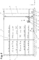
- FIG. 1 and 2 An embodiment of a storage system is shown. This comprises stationary storage racks 1, at least one automated general cargo receiving device 2 and an automated conveyor technology 3.
- the storage racks 1 each form a multiplicity of storage channels 4, which are provided next to one another in superimposed shelf levels 5 and 5 per shelf level.
- These storage channels 4 can store piece goods 6 of different width dimensions 7 one behind the other in a depth direction (z direction) of the storage rack 1, only piece goods 6 of a single width class being located within a storage channel 4.
- the width classes are defined by an electronic control unit 8 before the piece goods 6 are stored, as will be described below.
- These piece goods 6 can also be of different length dimensions 9. As will be described in the following, depending on a length dimension 9 of the piece goods 6, either only a single (long) piece goods 6 or several (shorter) piece goods 6 are stored in a storage channel 4. If several (shorter) piece goods 6 are stored in a storage channel 4, they belong to a single width class.
- the piece goods 6 can either have the same length dimension 9 or different length dimensions 9.
- the piece goods 6 can be conveyed and stored without an additional loading aid (LHM), such as a tray or container.
- LHM loading aid
- the piece goods 6 are in particular packing units, for example cardboard boxes.
- the boxes contain articles, for example from the textile or food industry.
- These piece goods 6 have a width dimension 7 between 150 mm and 1,200 mm and a length dimension 9 between 200 mm and 2,000 mm.
- Some of the width classes B1..B10 are listed below as examples.
- the width deviation from an initial width dimension is approx. 50 mm.
- This width deviation can be matched, for example, to the quality of the cartons and / or the mechanical structure of the transport device to be described in more detail. This is mainly because different boxes are used depending on customer requirements. "Inferior" cardboard boxes have a lower inherent stiffness and tend to be deformed, in particular to be pressed in. In this case, the width deviation will be greater than with boxes of "higher" quality. Experience has shown that the width deviation can be between 50 mm and 200 mm. In Fig. 1 it is shown for one of the width classes that the piece goods 6 within a storage channel 4 can have different width dimensions 7, but these piece goods 6 nevertheless have this Belong to broad class.
- the first general cargo 6 has, for example, a width dimension 7 of 560 mm and the second general cargo 6 has, for example, a width dimension 7 of 580 mm.
- the storage racks 1 each include front rack uprights 10, rear rack uprights 11, front longitudinal cross members 12 and rear longitudinal cross members 13 fastened to them, and one storage shelf 5 arranged between each of the longitudinal cross members 12, 13 and fastened to them.
- the storage floor 14 forms on the top side a bearing surface 15, which extends per shelf level 5 in the depth direction (z direction) between the front longitudinal cross member 12 and rear longitudinal cross members 13.
- the storage surface 15 per shelf level 5 extends at least between the successive front rack uprights 10 and rear rack uprights 11.
- bearing channels 4 are formed on the bearing surface 15, whereby the term “bearing channel” is to be understood in such a way that it is fictitiously defined by the control unit 8 as a footprint. In Fig. 1 the bearing channels 4 are indicated by dashed lines. Depending on the width class and thus the width dimension 7 of the piece goods 6 which are to be stored in a storage channel 4, a width of the (fictitious) storage channel 4 is also determined by the control unit 8.
- 5 storage zones 16, 17 can be defined in the storage rack 1 per shelf level, the control unit 8 assigning different width classes to the storage zones 16, 17, for example a width zone B1..B6 and a second storage zone 17 the width classes B7 .. B10.
- width class B1 can be stored in the first storage zone 16
- width class B4 can be stored in the second storage zone 17.
- the piece goods receiving device 2 shown is mounted on a support frame 18 and can be moved along the storage racks 1 in a first direction (x direction) and vertically in a second direction (y direction).
- a plurality of piece goods receiving devices 2 can also be mounted on the support frame 18, but this is not shown.
- the piece goods receiving device 2 is located in a shelf aisle 19 formed between the storage racks 1 ( Fig. 1 ) arranged.
- the support frame 18 ( Fig. 3 ) is mounted on a travel unit 20, in particular a conveyor vehicle.
- the travel unit 20 is designed as a shelf conveyor vehicle and comprises a vertical mast 21, a lower carriage 22 attached to the mast foot, an upper carriage 23 attached to the mast head.
- the lower carriage 22 is on a lower guide rail 24 and the upper carriage 23 on an upper guide rail 25 guided.
- the support frame 18 is mounted on the vertical mast 21 in a height-adjustable manner in the y direction via a lifting drive 26.
- the stroke drive 26 is connected by a traction mechanism drive 27 and at least one electric drive motor 28 ( Fig. 1 ) educated.
- the electric drive motor 28 is connected to the control unit 8 in order to receive control signals.
- the travel unit 20 is mounted on the guide rails 24, 25 so that it can be moved in the x direction via a travel drive 29.
- the lower undercarriage 21 comprises the travel drive 29, which is formed by at least one electric drive motor 30 and a drive roller 31 coupled to it. Two drive motors 30 and two drive rollers 31 are preferably provided.
- the electric drive motor (s) 30 is / are connected to the control unit 8 in order to receive control signals.
- Such a moving unit 20 is, for example, in FIG EP 2 419 365 B1 and is the subject of this disclosure.
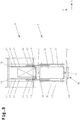
- the piece goods receiving device 2 As in the 1 to 3 can be seen, on the support frame 18 which is movable in a first direction (x direction) and second direction (y direction), the piece goods receiving device 2 and an (automated) transport device 32 which can be extended into the storage channel 4 in a third direction (z direction) Storage of piece goods 6 in the storage channels 4 and removal of piece goods 6 from the storage channels 4 mounted.
- the piece goods receiving device 2 is in the Fig. 1 and 2 only shown schematically for the sake of a better overview.
- the general cargo receiving device 2 as detailed in its functional units in Fig. 3 a motorized conveyor device 33 may be shown.
- the conveyor device 33 is, for example, a belt conveyor or roller conveyor, the length of the transport surface 34 of which is essentially the maximum storage depth 35 ( Fig. 8a ) of a storage channel 4 and the width essentially corresponds to the maximum width dimension 7 of a piece good 6.
- the belt conveyor is operated by at least one drive motor 36 ( Fig. 2 ) driven. If the conveyor device 33 is a roller conveyor, some of the conveyor rollers or all of the conveyor rollers can each be equipped with an electric drive motor, the drive motor being arranged within the roller body.
- the electric drive motor (s) of the belt conveyor / roller conveyor is / are connected to the control unit 8 in order to receive control signals.
- the piece goods receiving device 2 can also have support means 37 arranged in the opposite end regions of the motorized conveying device 33.
- the support means 37 are each formed by a conveyor device 38 with non-driven support rollers or preferably in each case by a motorized conveyor device 38.
- a particularly simple construction results if the motorized conveying devices 38 are each formed by a driven support roller.
- This driven support roller can be equipped with an electric drive motor arranged within it, the drive motor being arranged within the roller body.
- the electric drive motors are connected to the control unit 8 in order to receive control signals.
- a transport surface 34 of the conveying device 33 and a (not entered) transport surface of the conveying device 38 run in a common plane.
- the support means 37 serves to support the load of the piece goods 6 when they are shifted between the piece goods receiving device 2 and the storage channel 4. If the support means 37 is formed by a motorized conveyor device 38, the piece goods 6 can also be subjected to a driving force.
- the driving force is selected such that a feed speed of the conveying device 38, in particular the motorized support roller, is higher than a feed speed of the conveying device 33.
- the piece goods receiving device 2 can also have stop elements 39, 40 arranged in the opposite end regions of the motorized conveying device 33. These are adjustably mounted on the support frame 18 between an initial position moved out of the transport path of the piece goods 6 along the conveyor device 33 and an actuation position moved into the transport route of the piece goods 6 along the conveyor device 33.
- the stop elements 39, 40 are each with a (in Fig. 2 schematically indicated) coupled actuator, which comprises a drive motor.
- the drive motors are connected to the control unit 8 in order to receive control signals.
- the piece goods receiving device 2 can also have a sensor system, which is set up to detect the piece goods 6 on the piece goods receiving device 2. This is connected to the control unit 8 in order to ascertain an actual length of the groupage of goods on the package receiving device 2.
- the sensor system is formed by measuring devices 41 arranged in the opposite end regions of the conveying device 33, which measure a distance from the foremost piece goods 6 of the piece goods group.
- the control unit 8 uses the measured values to determine an actual length of the general cargo group, which is located on the general cargo receiving device 2 after the transfer.
- the measuring devices 41 are optoelectronic measuring systems, in particular laser or infrared measuring systems.
- the sensor system can also be an image processing system with a camera.
- the transport device 32 shown can be extended in both directions relative to the piece goods receiving device 2, so that piece goods 6 or piece goods 6 can be stored in the storage racks 1 arranged on both sides of the piece goods receiving device 2.
- the transport device 32 can comprise telescoping units 42 arranged parallel to one another on the support frame 18, each of which has a base frame 43 and slides 44, 45 that can be retracted or extended synchronously in one direction (z direction) relative to the base frame 43.
- the telescopic units 42 form telescopic arms.
- the first slide 44 is slidably mounted on the base frame 43 and the second slide 45 is slidably mounted on the first slide 44.
- the first carriage 44 can be moved relative to the base frame 43 with the aid of a drive device (not shown), for example a drive chain and toothed rack arrangement, relative to the base frame 43.
- the chain drive is connected to an electric drive motor 46 ( Fig. 2 ) coupled.
- the electric drive motor 46 is connected to the control unit 8 in order to receive control signals.
- a first belt (not shown) is deflected around a first roller mounted on the first slide 44 and fastened with its first end to the base frame 43 and with its second end to the second slide 45.
- a second belt (not shown) is deflected around a second roller mounted on the first slide 44 and fastened with its first end to the base frame 43 and with its second end to the second slide 45. If the first carriage 44 is moved by the drive device, the second carriage 45 is also moved via the belts, that is to say moved in or out.
- the second carriage 45 comprises drive motors 47 for transport members 48, 49 for transporting piece goods 6 between the storage channel 4 and the piece goods receiving device 2.
- the transport members 48, 49 are arranged in the opposite end regions of the second carriage 45, each transport member 48 , 49 (driving element) is coupled to a drive motor 47 and can be moved between an initial position and an actuating position. In the starting position, the transport members 48, 49 are moved out of a transport path for the piece goods 6 so that the piece goods 6 can pass the transport members 48, 49, and in the actuation position the transport members 48, 49 are moved into the transport path for the piece goods 6 , so that the transport members 48, 49 engage behind the piece goods 6 in a form-fitting manner.
- the telescopic units 42 are also preferably mounted on the support frame 18 via an actuator relative to one another and adjustable in an x-direction. In this way, a distance between the telescopic units 42 can be varied and set to the respective width classes B1..B10.
- the actuator comprises at least one electric drive motor 50 which is connected to the control unit 8 in order to receive control signals.
- an automated conveyor technology 3 which has a first conveyor device 51 for the transport of piece goods 6 to the piece goods receiving device 2 and a second conveyor device 52 for the removal of piece goods 6 from the piece goods receiving device 2.
- the first conveying device 51 connects to a discharge point 67 upstream of this in the conveying direction.
- the second conveying device 51 connects to an insertion point 68 located downstream of this in the conveying direction.
- the second conveyor device 52 leads to a logistical work process, not shown, where, for example, customer orders are picked automatically or manually, or consolidated.
- the first conveying device 51 forms a staging area 53, on which piece goods 6 of a broad class, for example the broad class B2, are put together.
- the piece goods 6 of this width class are positioned against a stop element 54 and lying close together to form a piece goods group.
- the stop element 54 is assigned to the first conveying device 51 in a downstream end region and by means of an actuator 55 ( Fig. 2 ), for example a pneumatically operated lifting cylinder, between an initial position moved out of the transport path of the piece goods 6 along the conveying device 51 and an actuating position moved into the transport path of the piece goods 6 along the conveying device 51 adjustable on a support frame.
- an actuator 55 for example a pneumatically operated lifting cylinder
- the first conveying device 51 for the transport of piece goods 6 forms a first conveying section, a second conveying section and a third conveying section in the conveying direction.
- a staging area 53 is formed in the first conveyor section.
- the staging area 53 is formed, for example, by a roller conveyor, belt conveyor and the like. If the supply location 53 is a roller conveyor, some or all of the conveyor rollers can be so-called motor rollers.
- a lifting and lowering belt converter 56 is arranged, which connects the first conveyor section and third conveyor section with each other in terms of conveying technology.
- the third conveyor section is formed, for example, by a roller conveyor, belt conveyor and the like.
- the second conveying device 52 for the transport of piece goods 6 forms a first conveying section, a second conveying section and a third conveying section in the conveying direction.
- a takeover place 57 is formed in the first funding section.
- the takeover place 57 is formed, for example, by a roller conveyor, belt conveyor and the like. If the transfer location 57 is a roller conveyor, some or all of the conveyor rollers can be so-called motor rollers.
- a lifting and lowering belt converter 56 is arranged, which is the first conveyor section and third conveyor section connects with each other in terms of conveyor technology.
- the third conveyor section is formed, for example, by a roller conveyor, belt conveyor and the like.
- a measuring station 58 in particular an optical measuring station, is arranged along the automated conveyor technology 3, at which preferably each piece good 6 is measured without contact.
- the measuring station 58 is preferably located in front of a discharge point 67, at which piece goods 6 are delivered to the first conveyor device 51.
- the (maximum) width dimension 7 and (maximum) length dimension 9 of a piece good 6 are preferably recorded.
- a volume measurement of the piece goods 6 is also conceivable.
- the piece goods 6 only to determine the width dimension 7.
- the width dimension 7 corresponds to that dimension of a piece goods 6, which runs transversely to the longitudinal extent of the storage channel 4 when the piece goods 6 has been stored in the storage channel 4.
- the length dimension 9 corresponds to that dimension of a piece goods 6, which runs in the direction of the longitudinal extent of the storage channel 4 when the piece goods 6 has been stored in the storage channel 4.
- the measuring station 58 is connected to the control unit 8 in order to transmit the actual values of the width dimension 7 or width dimension 7 and length dimension 9 to an electronic evaluation module 59.
- the control unit 8 controls the piece goods receiving device 2, the transport device 32 and / or the conveyor device 51 for the transport of piece goods 6 to the piece goods receiving device 2 in order to select the piece goods 6 according to width classes to at least one staging area 53 to convey and to receive the piece goods 6 provided on the piece goods receiving device 2 and to store the piece goods 6 taken over on the piece goods receiving device 2 in a storage channel 4 of a defined width class.
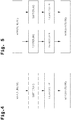
- Fig. 4 shows a storage system according to Fig. 1 with two storage racks 1 and at least one piece goods receiving device 2, the storage system connecting to a goods receipt and a goods issue.
- the piece goods 6 are delivered to the goods receipt and by means of the first conveying device 51 to the storage system, where they are picked up and stored by the piece goods receiving device 2.
- the term “similar” is to be understood here in such a way that the articles do not necessarily have to be the same, but their width dimensions 7 and / or length dimensions 9. If, for example, the delivery of goods concerns shirts, these can be sorted according to size.
- the first boxes contain the X-Large shirts
- the second boxes contain the Large shirts
- the third boxes contain the Medium shirts
- the fourth boxes contain the Small shirts.
- all boxes are of the same width and length.
- the boxes can be delivered by the supplier directly to at least one feed station (not shown), which connects to the first conveyor device 51, and can be removed by the first conveyor device 51.
- the cartons can also be delivered on a load carrier, for example on a pallet, so that the cartons stacked on the load carrier must be separated and transferred to the first conveyor device 51. The separation can be done manually or automatically.
- Sorting can be done manually or automatically. If automatic sorting is provided, the Conveyor technology 3 has a sorting device (not shown), by means of which the piece goods 6 are sorted at least according to their width dimensions 7 and are fed to the staging area 53 in the sorted order by means of the first conveying device 51.
- Such an automatic sorting device is preferably arranged in the conveying direction of the piece goods 6 along the first conveying device 51 after the measuring station 58.
- the supplier it is also possible for the supplier to transfer the different piece goods 6, sorted according to size and width dimension 7, to the first conveyor device 51. In this case, a separate sorting device is not required before storage.
- Different width classes are thus made available in succession at the supply location 53.
- general cargo 6 of a first breadth class in a corresponding number as a bulk goods group and subsequently bulk goods 6 of another breadth class in a corresponding number as a bulk goods group are initially provided at the supply location 53.
- the sorting described can also be carried out according to width dimensions 7 and length dimensions 9 of the piece goods 6, with sorting primarily according to width dimension 7, so that only piece goods 6 of a single width class are contained within a piece goods group, while the length dimensions 9 of the piece goods 6 can vary.
- the piece goods 6 are selectively fed to the staging area 53 at least depending on their width dimension 7.
- the group of piece goods 6 of a first width class and then a group of piece goods 6 of a second width class are initially made available in succession on the staging area 53.
- the first general cargo group comprises at least two general cargo 6 of the same first width dimension 7 and the second general cargo group comprises at least two general cargo 6 of the same second width dimension 7.
- control unit 8 receives a picking order or removal order, which in turn controls the piece goods receiving device 2 and the transport device 32 in order to outsource the desired piece goods 6 for this order.
- the General cargo receiving device 2 conveys the general cargo 6 to the take-over location 57, where they are transported away by the second conveying device 52.
- the articles are, for example, shirts, pullovers, T-shirts and the like.
- the article type is used, for example, to define the size, color and the like.
- the article "shirt” of size X-Large and color white can form a first piece 6,
- the article "shirt” of size Large and color white can form a second piece 6, etc.
- the article "shirt” of size X-Large and color black form a third piece 6,
- the article "shirt” of size large and color black form a fourth piece 6 etc.
- the piece goods 6 with the article "shirt” in this case each have the same width dimensions 7 and length dimensions 9. Es it is possible to sort these (same) piece goods 6 according to article type. For example, initially all first piece goods 6 and then all second piece goods 6 etc. are transferred to conveyor system 3.
- the article "sweater” of size X-Large and color white can form a fifth piece 6, the article “Sweater” size large and color white can form a sixth piece 6 etc.
- the fifth / sixth piece 6 with article “sweater” have the same width dimensions 7 and length dimensions 9, but a different width dimension 7 and length dimension 9 than the first / second / third / fourth piece goods 6 with the article" shirt ".
- the first / second / third / fourth piece goods 6 and fifth / sixth piece goods 6, however, are selectively fed by the conveyor technology 3 to the staging area 53.
- Fig. 5 shows the sequence of several storage systems according to Fig. 1 with two storage racks 1 and at least one piece goods receiving device 2 per storage system, the storage systems connecting to a common goods receipt and a common goods issue.
- the piece goods 6 are delivered to the goods receipt and each by means of conveyed first conveyor device 51 to the respective storage system, where they are picked up and stored by the piece goods receiving device 2, as above in Fig. 4 described.
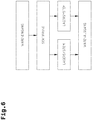
- Fig. 6 shows the sequence of several storage systems according to Fig. 1 with two storage racks 1 and at least one piece goods receiving device 2 for each storage system, the storage systems connecting to a common goods receipt and a common goods issue and to a common sorting device having the conveyor technology 3.
- the sorting device comprises a closed distribution system (conveyor orbit) with a first conveyor section, a second conveyor section and third conveyor sections connecting them.
- the first conveyor section is adjoined by a large number of feed stations, so that the piece goods 6 or cartons that are delivered by the suppliers at the feed stations and possibly different are introduced into the distribution system.
- the boxes can also be delivered on load carriers, for example pallets, so that the boxes stacked on the load carriers are separated and introduced into the distribution system. The separation can be done manually or automatically.
- the conveying device 51 of the first storage system and the conveying device 51 of the second storage system are connected to the second conveying section.
- the distribution system can supply different piece goods 6, sorted at least according to their width dimensions 7, to the conveying device 51 of the first storage system and conveying device 51 of the second storage system. Different width classes are successively provided at the first staging area 53 of the first storage system and different width classes are successively provided at the second staging area 53 of the second storage system.
- the sorting can also be controlled such that at the first staging area 53 of the first storage system and at the second staging area 53 of the second storage system General cargo 6 of the same breadth classes are provided in parallel. A uniform distribution of the different piece goods 6 is thus achieved in the storage systems, so that picking orders can be processed in parallel by several piece goods receiving devices 2.
- width classes B1..B5 in the first storage system are stored in the storage systems, for example width classes B1..B5 in the first storage system and width classes B6..B10 in the second storage system.
- width classes B1..B5 in the first storage system are stored in the storage systems, for example width classes B1..B5 in the first storage system and width classes B6..B10 in the second storage system.
- Such an application is advantageous if there is a higher variety of articles but a lower turnover rate in one of the storage systems (first storage system) and a comparatively low variety of articles with a higher turnover rate in another of the storage systems (second storage system).
- a particularly high overall performance can be achieved by parallelizing the storage processes.
- the sorting described can also be carried out according to width dimensions 7 and length dimensions 9 of the piece goods 6, with sorting primarily according to width dimension 7, so that only piece goods 6 of a single width class, for example the width class B2, are contained at the first staging area 53 within a piece goods group, while the length dimensions 9 of the piece goods 6 can vary, and only piece goods 6 of a single breadth class, for example the breadth class B6, are contained at the second supply location 53 within a piece goods group, while the length dimensions 9 of the piece goods 6 can vary.
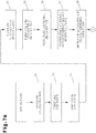
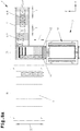
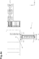
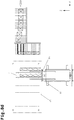
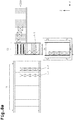
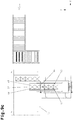
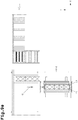
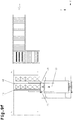
- Fig. 7a . 7b and 8a-8e the process sequence for storing piece goods 6 in at least one of a plurality of storage channels 4 is shown on the basis of a flow diagram and sequence sequence.
- the piece goods 6 are delivered to the goods receipt.
- storage orders are recorded electronically, for example on an input device, for example a computer.
- the storage orders comprise different piece goods 6.
- the storage orders are continuously transmitted to the control unit 8, which in turn coordinates the control of the conveyor technology, piece goods receiving device 2 and transport device 32.
- the piece goods 6 are conveyed by the conveyor technology from the goods receipt to the storage system, step S2. Before the piece goods 6 are fed to the staging area 53, they can be measured in an (optional) step S3 in the manner described above.
- the evaluation module 59 ( Fig. 1 )
- the control unit 8 preferably determines the actual value of the width dimension 7 or the actual values of the width dimension 7 and length dimension 9 for each piece good 6. This is the maximum width dimension 7 and possibly maximum length dimension 9 (along a circumferential line) of the piece goods 6. Alternatively, The control unit 8 also receives the setpoint of the width dimension 7 or the setpoints of the width dimension 7 and length dimension 9 for each piece good 6, which are stored as master data in a database.
- the piece goods 6 are identified on the basis of a data carrier, for example barcode or an RFID (Radio Frequency Identification Device) and a piece goods identification device, for example a reading device or image processing system.
- a data carrier for example barcode or an RFID (Radio Frequency Identification Device)
- a piece goods identification device for example a reading device or image processing system.
- an identification code is read from a data carrier attached by the supplier to each carton (packing unit) or a load carrier (for example a pallet) on which similar piece goods 6 are stacked, in particular a barcode is scanned.
- the database and the stored setpoints of the width dimension 7 or the setpoints of the width dimension 7 and length dimension 9 of the piece goods 6 are used.
- dimensional or shape deviations of the cartons (packing units) can also be taken into account in the control of the transport device 32 and / or conveyor technology.
- control unit 8 determines that the piece goods 6 for a storage order cannot be stored in the desired number in a storage channel 4, since the available storage depth 35 is too small. It would thus be possible to store general cargo 6 of a broad class and in a calculated number in a storage channel 4 if the general cargo 6 has a length dimension 9, which are stored as target values in the master data. For example, according to the target values for the length dimension 9 per piece good 6, the piece goods 6 of a width class B6 could be stored in a storage channel 4 in a number of four pieces.
- control unit 8 has evaluated the actual values of the piece goods 6 and has determined an actual length of the “planned” piece goods group, which corresponds to or exceeds the maximum available storage depth 35. Accordingly, it would not be possible to store the "planned" general cargo group with the four general cargo 6 of width class B6, but only three general cargo 6, as in Fig. 1 entered in dashed lines.
- the control unit 8 can now control the conveyor technology 3 in such a way that only a “matched” number of piece goods 6 are discharged onto the first conveyor device 51 at the discharge point 67, hence three piece goods 6.
- step S4 the piece goods 6 are assigned to a corresponding width class B1..B10 depending on the width dimension 7. Either the actual values of width dimension 7 or nominal values of width dimension 7 can be used for this assignment. As described above, a piece good 6 with the width dimension 7 between 201 mm and 250 mm, for example, is assigned to the width class B2, a piece good 6 with the width dimension 7 between 501 mm and 550 mm, for example, the width class B8, etc. This assignment is carried out automatically by an analysis module 60 or a logic of the control unit 8.
- the width classes B1..B10 are defined before the storage system is put into operation and recorded on the control unit 8.
- the first storage order comprises the piece goods 6, which were assigned to the second breadth class B2
- the second storage order comprises the piece goods 6, which were assigned to the eighth breadth class B8.
- the first storage order comprises eight general cargo 6-2 of the second breadth class B2 and the second storage order six bulk goods 6-8 of the eighth breadth class B8.
- the piece goods 6-2, 6-8 are fed according to step S5 by the conveyor technology 3 selectively according to breadth class to at least one staging area 53 and made available in succession there, see Figures 8a - 8e ,
- the eight piece goods 6-2 of the second width class B2 are initially provided in succession at the at least one staging area 53.
- the six piece goods 6-8 of the eighth width class B8 are made available in succession at the at least one staging area 53.
- four piece goods 6-2 of the second breadth class B2 are also made available at a first staging area 53 and four piece goods 6-2 of the second breadth class B2 are made available at a second staging area 53.
- the six piece goods 6-8 of the eighth width class B4 are fed in the same way to the first staging area 53 and second staging area 53 and made available there.
- the control unit 8 determines the at least one storage channel 4, in which the piece goods 6 are to be stored according to a storage order. If the first storage order comprises more piece goods 6 than can be received in a storage channel 4, the control unit 8 determines a corresponding number of storage channels 4 in which the piece goods groups 61-2 (as in FIG Figures 8a - 8e shown).
- a particularly high storage performance is achieved if the control unit 8 determines the empty storage channels 4, in particular within a storage zone 16, 17.
- the entire storage depth 35 can be used and a maximum number of piece goods 6 can be stored.
- four piece goods 6-2 of width class B2 and with the existing length dimension 9 of piece goods 6-8 in the second storage zone 17 in the empty storage channel 4 three General cargo 6-8 of width class B8 can be included.
- the storage rack 1 is subdivided into storage zones 16, 17 and each storage zone 16, 17 forms a plurality of (fictitious) storage channels 4 provided next to one another.
- a first storage channel 4 is loaded with the piece goods 6 of a selected width class, for example width class B2
- the control unit 8 also determines the occupancy of the remaining storage channels 4 within the same storage zone 16, 17 depending on the occupancy of the first storage channel 4 such that after a first run (see 8a - 8e , Storage zone 16) also the remaining storage channels 4 only with piece goods 6 of the same breadth class, therefore all storage channels 4 are filled with piece goods 4 of the breadth class B2.
- a (right) first storage channel 4 is occupied with the piece goods 6 of a selected width class, for example width class B7.
- the remaining storage channels 4 will only be occupied with piece goods 6 of selected width classes, for example width classes B8-B10. It can be seen that the width classes B8-B10 are similar to the selected width class B6 in the first storage channel 4.
- the chaotic storage principle is therefore not followed, in which piece goods 6 are stored at any free storage channels 4, but rather a selected occupancy of the storage channels 4 graded according to width classes.
- the general cargo 6 of the width classes are conveyed from the general cargo receiving device 2 to the storage channels 4 of the storage zones 16, 17 and stored by the transport device 32 into the storage channels 4 of the storage zones 16, 17.
- step S7 the piece goods pick-up device 2 is positioned relative to the staging area 53 by its movement in a first direction (x direction) and possibly a second direction (y direction), see Fig. 8a ,
- the piece goods 6-2 are then conveyed from the supply station 53 onto the piece goods receiving device 2 and taken over on the piece goods receiving device 2, step S8.
- the piece goods 6-2 can be compressed into a piece goods group 61-2 before transfer to the piece goods receiving device 2, therefore the piece goods 6-2 are lined up closely together in the conveying direction.
- a compaction device 62 can be provided at the supply station 53.
- This is formed, for example, by the abutment element 54 described above, which is adjustable between the starting position moved out of the transport path of the piece goods 6-2 along the conveying device 51 and the actuating position moved into the transport path of the piece goods 6-2 along the conveying device 51, so that the piece goods 6-2 run against the stop element in the operating position.
- the piece goods receiving device 2 comprises the conveying device 33, the transport members 48, 49 and, if appropriate, the stop elements 39, 40. If the piece goods 6 on the piece goods receiving device 2 are conveyed by the conveying device 33, they can be positioned against the transport members 49 which are adjusted into the actuation position become. In the case of narrow piece goods 6-1 (piece goods of the first width class B1), the stop element 40 is moved into the actuation position, so that these piece goods 6 can be positioned against the stop element 40.
- the groupage 61-2 is only put together on the package receiving device 2. However, the groupage 61-2 already put together on the supply station 53 can be compressed again on the groupage pickup device 2 if it can be assumed that the groupage 6-2 move apart in the conveying direction on the conveying movement from the supply station 53 onto the groupage pickup device 2.
- the control unit 8 comprises an evaluation module 66 (analysis module) by means of which the actual length of the groupage group 61-2 is compared with a target length of the groupage group 61-2.
- the control unit 8 can determine a target length of the general cargo group 61-2 based on the storage order, the individual length dimensions 9 of the general cargo 6-2 originating from the measurement at the measuring station 58 and the target length corresponds to the sum of these length dimensions 9.
- the setpoints for the length dimensions 9 from the master data for the piece goods 6-2 can also be used. However, this presupposes that the piece goods 6 are dimensionally stable. If the actual length of the general cargo group 61-2 deviates from the target length of the general cargo group 61-2, a monitoring signal is triggered by the evaluation module 66 of the control unit 8. The deviation must be greater than the sum of the usual tolerance deviations due to deformation of the boxes (piece goods 6-2). For example if the deviation is more than 50 mm.
- the monitoring signal can be used to output an optical and / or acoustic fault message for an operator. Such a fault message is available if the piece goods 6-2 have not been properly transferred from the supply location 53 to the piece goods receiving device 2, for example if a piece goods 6-2 has been handed over to the piece goods receiving device 2 too little.
- step S9 the piece goods receiving device 2 is moved by its movement in a first direction (x direction) and possibly a second direction (y direction) relative to the storage channel 4 defined by the control unit 8, in which the piece goods group 61-2 is to be stored, positioned, see Fig. 8c ,
- the groupage 61-2 is conveyed by the transport device 32 from the piece pickup device 2 into the defined storage channel 4.
- the piece goods 6-2 are moved simultaneously via the transport members 49, which are arranged in the end region of the transport device 32 opposite in the displacement direction (insertion direction according to arrow 63). It goes without saying that the displacement is also possible with only one transport element 49, which is arranged in the end region of the transport device 32 opposite in the displacement direction (insertion direction according to arrow 63).
- the piece goods 6-2 are moved so far in the depth direction of the storage channel 4 that the rearmost piece goods 6-2 in the displacement direction (storage direction according to arrow 63) with its side wall 64 runs essentially flush with an end edge 65 of the storage channel 4, see Fig. 8d ,
- the term “essentially in alignment” is to be understood in such a way that the piece goods 6-2 can be offset with its side wall 64 with respect to the end edge 65 in the direction of the storage channel 4 to such an extent that an offset distance is less than 80 mm, for example 20 mm.
- the piece goods 6-2 can also protrude by the offset distance on the end edge 65 of the storage channel 4.
- the transport device 32 in particular the telescopic units 42, extended into the storage channel 4 is moved back into an initial position. It is also possible for the groupage goods group 61-2 to be positioned before the shift movement into the storage channel 4 by means of a centering stroke of the telescopic units 42 relative to the piece pick-up device 2, so that the groupage goods 6-2 are aligned exactly one after the other before they enter the storage channel 4 be promoted.
- the piece goods 6-2 of the piece goods group 61-2 on the piece goods receiving device 2 can again in a direction parallel to the longitudinal extent of the storage channel 4 and in front the relocation of the general cargo group 61-2 can be positioned by moving the general cargo 6-2 via the conveying device 33 against the loading direction 63 against the transport members 40 of the transport device 32 in an initial position and / or the stop element 40.
- This ensures that the piece goods 6-2 of the piece goods group 61-2 are lined up closely to one another before they are moved into the storage channel 4. Even if the piece goods 6-2 have slipped unexpectedly during the adjustment movement of the piece goods receiving device 2, this has no effect on the placement accuracy of the piece goods 6-2 in the storage channel 4.
- the piece goods receiving device 2 comprises support means 37, which serves as a guide support for the piece goods 6 to be stored.
- the support means 37 bridges the gap between the piece goods receiving device 2 and the front edge 65. This measure makes it possible to move piece goods 6 between the piece goods receiving device 2 and the storage channel 4, which have particularly short length dimensions 9, for example in the range of 150 mm , If the support means 37 is a driven conveyor device 38, the respective piece goods 6 are acted upon by a driving force during the displacement.
- the conveying speed of the conveying device 38 essentially corresponds to the extension speed of the transport device 32 when it is extended into the storage channel 4.
- the described storage process is repeated until all piece goods 6-2 have been stored in the plurality of storage channels 4 of the first storage zone 16, step S11.
- the second storage order comprising the piece goods 6-8 of the eighth width class B8 is then processed in the same way, the piece goods 6-8 being stored here in a plurality of storage channels 4 of the second storage zone 17.
- the piece goods 6 per storage channel 4 always have the same width dimensions 7, it is possible in the sense of the invention that 4 piece goods 6 of the same width class, for example width class B9, but with slightly different width dimensions 7 are stored in a storage channel, as in FIG Fig. 1 entered in one of the storage channels 4.
- the piece goods 6 deposited in the depth direction in the storage channel 4 at the front storage position have a width dimension of 560 mm and the piece goods 6 deposited in the depth direction in the storage channel 4 at the rear storage position have a width dimension of 600 mm. Both unit loads 6 have been assigned to width class B9 by the control unit 8.
- the control unit 8 first determines a free storage depth 35 in the defined storage channel 4, which remains minus the length dimension 9 of the intermediate piece goods 6-8 or the intermediate piece goods 6-8. The control unit 8 then determines the number of piece goods 6-8, which can also be stored in the defined storage channel 4 for this width class, for example width class B8.
- the piece goods receiving device 2 is initially positioned in front of the staging area 53 in order to take the piece goods or pieces 6-8 which can still be stored in the storage channel 4 of the width class B8.
- Fig. 9b three piece goods 6-8 were taken on the piece goods receiving device 2.
- Piece goods 6-8 can in turn be provided close together to form a piece goods group 61-8 on the piece goods receiving device 2, although this is not absolutely necessary. If the piece goods 6-8 are provided close together as piece goods group 61-8, the piece goods 61-8 can, as already in Fig. 7a . 7b , Step 8 described in detail, before the transfer to the piece goods receiving device 2 or only on the piece goods receiving device 2 to the piece goods group 61-8.
- the actual length of the general cargo group 61-8 can also be determined on the general cargo receiving device 2, as described above.
- the piece goods receiving device 2 is positioned opposite the storage channel 4 defined by the control unit 8, in which the piece goods 6-8 or the piece goods group 61-8 is to be stored.
- the general cargo 6-8 or the general cargo group 61-8 is / are positioned in a direction parallel to the depth direction of the storage channel 4 before the relocation process, as will be described below, by means of the conveying device 33.
- the stop element 39 is then moved into the starting position or the transport members 48 are moved into the starting position and the transport device 32 is extended into the storage channel 4.
- the transport device 32 is extended in the z direction to such an extent that a piece of goods 6-8 placed in the storage channel 4 at the foremost storage position passes over a side wall 69 facing away from the end edge 65.
- the transport device 32 is extended in the z direction to such an extent that a piece of goods 6-8 placed in the storage channel 4 at the lowest storage position passes over a side wall 69 facing away from the end edge 65.
- the transport members 48 are then moved into the actuating position.
- the control unit 8 controls the extension movement of the transport device 32, the control unit 8 also the extension path, preferably from the previously measured length dimension 9 (actual value of the length dimension 9) of the piece goods 6-8 or from the sum of the previously measured length dimensions 9 (actual values of the length dimensions 9) the piece goods 6-8 is determined.
- control unit 8 determines the extension path from the setpoint of the length dimension 9 of the piece goods 6-8 or the setpoint values of the length dimensions 9 of the piece goods 6-8, after the length dimension of each piece goods 6-8 in the master data 9 are deposited.
- Fig. 9d shows the rearrangement of two piece goods 6-8. If there is only one piece good 6-8 in the storage channel 4, then only this piece good 6-8 is relocated.
- the (two) piece goods 6-8 are moved from the storage channel 4 onto the piece goods receiving device 2 by the movement of the transport device 32 in a second displacement direction 70 (removal direction).
- the rear transport members 48 with respect to the second displacement direction 70 are moved into the actuation position before the transport device 32 is moved back into the starting position on the piece goods receiving device 2.
- the (two) piece goods 6-8 are displaced by the transport members 48 moved into the actuating position.
- the conveying device 33 is also driven such that the speed of movement of the conveying device 32 and conveying speed of the conveying device 33 are essentially synchronized.
- the (three) piece goods 6-8, which are already on the conveying device 33, and the (two) piece goods 6-8, which still have to be transferred to the conveying device 33, are simultaneously moved in the second displacement direction 70 (discharge direction).
- the (five) piece goods 6-8 of the width class B8 can be positioned by means of the conveying device 33 on the piece goods receiving device 2 to the (complete) piece goods group 61-8 in a direction parallel to the depth direction of the storage channel 4.
- the piece goods 6-8 are pressed against the stop element 40 (which is removed from the storage channel 4 in which the piece goods group 61-8 is to be stored).
- Fig. 3 which has been moved into the actuating position, or the removed transport members 49, which have been moved into the actuating position, in which the conveying device 33 is driven with a conveying direction away from the storage channel 4, therefore in the unloading direction 70.
- the transport members 48 adjacent to the storage channel 4 in which the groupage 61-8 is to be stored are moved back into the starting position.
- Fig. 9f finally shows the displacement of the groupage 61-8 formed from the package receiving device 2 into the storage channel 4 by means of the transport device 32.
- the package goods 6-8 are simultaneously moved in a first direction of displacement 63 (storage direction) and as far in the depth direction of the storage channel 4 that the in Direction of displacement 63 (Storage direction) the rearmost piece goods 6-8 with its side wall 64 are essentially flush with an end edge 65 of the storage channel 4.
- the transport members 49 which have been moved into the actuating position, are used.
- the general cargo 6-8 of the general cargo group 61-8 on the general cargo receiving device 2 can be aligned in a direction transverse to the longitudinal extent of the storage channel 4.
- the groupage goods group 61-8 it is possible for the groupage goods group 61-8 to be positioned before the shift movement into the storage channel 4 by means of a centering stroke of the telescopic units 42 relative to the piece pick-up device 2, so that the groupage goods 6-8 are aligned exactly one after the other before they enter the storage channel 4 be promoted.
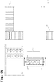
- FIG. 10a - 10b the outsourcing of a general cargo group 61-8, using the example of the general cargo group 61-8 to the general cargo receiving device 2 positioned in front of a storage channel 4 is described. Otherwise, only a single piece goods 6-8 can be removed from storage channel 4.
- the number of piece goods 6-8 to be outsourced is determined by a picking or removal order.
- the removal order is recorded electronically, for example on an input device (computer).
- the removal order can comprise a large number of similar piece goods 6, so that whole piece goods groups 61-8 can be removed, with which a high removal rate is achieved.
- a single piece goods 6-8 or the piece goods group 61-8 is moved from the storage channel 4 to the piece goods receiving device 2 by means of the transport device 32 such that the transport device 32 simultaneously moves all piece goods 6-8 located in the storage channel 4 in a second displacement direction 70 (discharge direction ) and moved out of the storage channel 4 until the desired number of piece goods 6-8 or the piece goods group 61-8 is positioned on the piece goods receiving device 2.
- the transport device 32 is extended in the z direction to such an extent that it passes the piece goods 6-8 (of several piece goods 6-8) placed in the deepest storage position in the storage channel 4 on a side wall 69 facing away from the end edge 65.
- the transport members 48 are then moved into the actuating position.
- the control unit 8 controls the extension movement of the transport device 32, the control unit 8 determining the extension path, preferably from the previously measured length dimension 9 (actual value of the Length dimension 9) of a piece goods 6-8 or from the sum of the previously measured length dimensions 9 (actual values of the length dimensions 9) of several piece goods 6-4.
- the control unit 8 it would also be possible for the control unit 8 to determine the extension path from the target values for the length dimensions 9 of the piece goods 6-4, after the length dimension 9 of each piece goods 6-4 has been stored in the master data.
- the conveying device 33 With the movement of the transport device 32 back into the starting position, the (four) piece goods 6-8 are displaced by the transport members 48 moved into the actuating position. With the takeover of the first piece goods 6-8 on the piece goods receiving device 2, the conveying device 33 is also driven such that the speed of movement of the conveying device 32 and conveying speed of the conveying device 33 are essentially synchronized.
- the piece goods 6-8 are on the piece goods receiving device 2 against the stop element 40 removed from the storage channel 4, from which the piece goods 6-8 were removed, which was moved into the actuating position, or the removed transport members 49, which were moved into the actuating position, positioned in which the conveying device 33 is driven with a conveying direction away from the storage channel 4, therefore in the unloading direction 70.
- the groupage receiving device 2 is moved to the second conveyor device 52 and positioned in front of the second conveyor device 52.
- the groupage 61-8 is then conveyed onto the second conveyor device 52.
- the storage system shown is a possible version.
- the piece goods receiving device 2 it is also possible for the piece goods receiving device 2 to be arranged on a walking beam device which is set up in a stationary manner and comprises a walking beam which can be moved vertically in the y direction and at least one piece goods receiving device 2 which can be moved along the walking beam in the x direction.
- a transport device 32 which can be extended relative to it in the z-direction in the storage channel 4, is mounted on the piece goods receiving device 2.
- the storage system can also have a multiplicity of piece goods receiving devices 2, which are each mounted on a movement unit which can be moved exclusively in the x direction.
- Such process units are from the State of the art is very well known and are so-called single-level shelf operating devices (shuttle), see for example the WO 2013/090970 A2 ,
- the transport device 32 described above for storing piece goods 6 in the storage channels 4 and removing piece goods 6 from the storage channels 4 on every second carriage 45 is equipped with an additional transport element which is arranged between the outer transport elements 48, 49, whereby also the additional transport member is coupled to a drive motor and can be moved between an initial position and an actuated position via the latter.
- the additional transport elements are always kept in the (inactive) starting position for the method described above.
- the control unit 8 can also control these additional transport members.
- storage zones 16, 17 can be formed, in which, on the one hand, the piece goods 6 in the storage channels 4 are stored close to one another and on the other hand the piece goods 6 are stored in the storage channels 4 with a mutual spacing ,
Landscapes
- Engineering & Computer Science (AREA)
- Mechanical Engineering (AREA)
- Warehouses Or Storage Devices (AREA)
Applications Claiming Priority (3)
| Application Number | Priority Date | Filing Date | Title |
|---|---|---|---|
| ATA50179/2015A AT516875B1 (de) | 2015-03-06 | 2015-03-06 | Verfahren zum Einlagern von Stückgütern in ein Lagerregal und Lagersystem |
| PCT/AT2016/050034 WO2016141395A1 (fr) | 2015-03-06 | 2016-02-19 | Procédé de mise en stock de marchandises au détail dans un rayonnage de stockage et système de stockage |
| EP16718988.5A EP3265406B1 (fr) | 2015-03-06 | 2016-02-19 | Procédé de mise en stock de marchandises au détail dans un rayonnage de stockage et système de stockage |
Related Parent Applications (2)
| Application Number | Title | Priority Date | Filing Date |
|---|---|---|---|
| EP16718988.5A Division EP3265406B1 (fr) | 2015-03-06 | 2016-02-19 | Procédé de mise en stock de marchandises au détail dans un rayonnage de stockage et système de stockage |
| EP16718988.5A Division-Into EP3265406B1 (fr) | 2015-03-06 | 2016-02-19 | Procédé de mise en stock de marchandises au détail dans un rayonnage de stockage et système de stockage |
Publications (2)
| Publication Number | Publication Date |
|---|---|
| EP3584197A1 true EP3584197A1 (fr) | 2019-12-25 |
| EP3584197B1 EP3584197B1 (fr) | 2022-08-03 |
Family
ID=55858717
Family Applications (2)
| Application Number | Title | Priority Date | Filing Date |
|---|---|---|---|
| EP16718988.5A Active EP3265406B1 (fr) | 2015-03-06 | 2016-02-19 | Procédé de mise en stock de marchandises au détail dans un rayonnage de stockage et système de stockage |
| EP19184795.3A Active EP3584197B1 (fr) | 2015-03-06 | 2016-02-19 | Système de stockage |
Family Applications Before (1)
| Application Number | Title | Priority Date | Filing Date |
|---|---|---|---|
| EP16718988.5A Active EP3265406B1 (fr) | 2015-03-06 | 2016-02-19 | Procédé de mise en stock de marchandises au détail dans un rayonnage de stockage et système de stockage |
Country Status (5)
| Country | Link |
|---|---|
| US (1) | US10322876B2 (fr) |
| EP (2) | EP3265406B1 (fr) |
| AT (1) | AT516875B1 (fr) |
| ES (2) | ES2929399T3 (fr) |
| WO (1) | WO2016141395A1 (fr) |
Cited By (2)
| Publication number | Priority date | Publication date | Assignee | Title |
|---|---|---|---|---|
| DE102020101689A1 (de) | 2020-01-24 | 2021-07-29 | Telejet Kommunikations Gmbh | Lagerungsverfahren sowie hierfür geeignetes Flächenlager |
| WO2022162170A1 (fr) * | 2021-01-29 | 2022-08-04 | Autostore Technology AS | Commande d'emplacements de stockage de produits stockés dans des conteneurs de stockage dans un système de stockage et de récupération automatisé |
Families Citing this family (25)
| Publication number | Priority date | Publication date | Assignee | Title |
|---|---|---|---|---|
| AT519050A1 (de) * | 2016-09-13 | 2018-03-15 | Tgw Mechanics Gmbh | Schienensystem für ein Förderfahrzeug und Lagersystem |
| JP6729491B2 (ja) * | 2017-05-25 | 2020-07-22 | 株式会社ダイフク | 物品移載装置 |
| WO2018231222A1 (fr) * | 2017-06-14 | 2018-12-20 | Lydle Richard C | Systèmes et procédés de manipulation de conteneurs d'expédition |
| CN108058967A (zh) * | 2017-12-13 | 2018-05-22 | 格力电器(武汉)有限公司 | 一种分装发货设备 |
| CN109292344B (zh) * | 2018-11-16 | 2024-02-09 | 罗博特科智能科技股份有限公司 | 一种拼接式物料存储仓 |
| AT16745U1 (de) | 2019-05-27 | 2020-07-15 | Tgw Mechanics Gmbh | Regallagersystem und Regalrahmenteil für ein Regallagersystem |
| DE202019102977U1 (de) | 2019-05-27 | 2019-06-05 | Tgw Mechanics Gmbh | Regallagersystem und Regalrahmenteil für ein Regallagersystem |
| DE102019124466B3 (de) * | 2019-09-11 | 2021-01-21 | Dematic Gmbh | Verfahren zum vollautomatischen Beladen eines mobilen Regals |
| DE102019129124B4 (de) * | 2019-10-29 | 2021-06-17 | Audi Ag | Flexibles Kommissionierspeichersystem für Behälter unterschiedlicher Dimensionierung |
| DE102020202912A1 (de) * | 2020-03-06 | 2021-09-09 | Kardex Produktion Deutschland Gmbh | Lagersystem mit zwei schräg zueinander ausgerichteten Übergabepositionen |
| IT202000009502A1 (it) * | 2020-04-30 | 2021-10-30 | System Logistics S P A | Elevatore per impianti di immagazzinamento automatici |
| US12172837B2 (en) * | 2020-05-27 | 2024-12-24 | Dematic Corp. | Robotic automated storage and retrieval system and method of storing articles |
| US11978012B2 (en) | 2020-10-28 | 2024-05-07 | United Parcel Service Of America, Inc. | Locating, identifying, and shifting objects in automated or semi-automated fashion including during transit |
| US12321889B2 (en) | 2020-10-28 | 2025-06-03 | United Parcel Service Of America, Inc. | Locating, identifying, and shifting objects in automated or semi-automated fashion including during transit |
| US11887048B2 (en) * | 2020-10-28 | 2024-01-30 | United Parcel Service Of America, Inc. | Locating, identifying, and shifting objects in automated or semi-automated fashion including during transit |
| CN114506610B (zh) * | 2020-11-20 | 2023-09-26 | 深圳市海柔创新科技有限公司 | 空间分配方法、货物存放方法、装置、机器人和仓储系统 |
| JP7298589B2 (ja) * | 2020-12-15 | 2023-06-27 | 株式会社ダイフク | 物品収容設備 |
| JP7314924B2 (ja) * | 2020-12-22 | 2023-07-26 | 株式会社ダイフク | 物品収容設備 |
| AT524700A1 (de) * | 2021-01-29 | 2022-08-15 | Tgw Mechanics Gmbh | Verfahren zum Einlagern mehrerer Lagerobjekte unterschiedlicher Lagerobjekttype in ein Lagerregal und ein Regallagersystem hierfür |
| CN113239832B (zh) * | 2021-05-20 | 2023-02-17 | 众芯汉创(北京)科技有限公司 | 基于图像识别的隐患智能识别方法及系统 |
| IT202300003996A1 (it) * | 2023-03-06 | 2024-09-06 | Pharmathek S R L | Unità e procedimento di trasferimento automatizzato di elementi scatolari |
| IT202300017028A1 (it) * | 2023-08-09 | 2025-02-09 | Ambrosi S R L | Magazzino verticale |
| EP4614265A1 (fr) | 2024-03-06 | 2025-09-10 | TGW Logistics GmbH | Dispositif et procédé pour éliminer des perturbations dans des installations de transport de marchandises |
| EP4620866B1 (fr) * | 2024-03-20 | 2026-04-08 | Pharmathek S.r.L. | Unité de manipulation automatisée et procédé pour articles en boîte |
| CN118657473B (zh) * | 2024-08-22 | 2024-10-22 | 华远陆港跨境电子商务有限公司 | 一种基于计算机的大数据分析控制系统 |
Citations (17)
| Publication number | Priority date | Publication date | Assignee | Title |
|---|---|---|---|---|
| JP2000118639A (ja) | 1998-10-19 | 2000-04-25 | Itoki Crebio Corp | 自動倉庫及びその入庫方法 |
| US6923612B2 (en) | 2002-03-29 | 2005-08-02 | TGW Transportgeräte GmbH & Co. KG | Load-handling system and telescopic arm therefor |
| JP2005219832A (ja) | 2004-02-03 | 2005-08-18 | Toyota Industries Corp | 自動倉庫の制御装置 |
| EP1627830A1 (fr) | 2004-08-16 | 2006-02-22 | Moving Ab | Dispositif et procédé de manutention et d'emmagasinage d'objets |
| DE102004046176A1 (de) | 2004-09-23 | 2006-04-06 | Kht Kommissionier- Und Handhabungstechnik Gmbh | Verfahren zum rechnergesteuerten Ein- und Auslagern von Gegenständen und Vorrichtung zur Durchführung dieses Verfahrens |
| JP2008143660A (ja) | 2006-12-11 | 2008-06-26 | Seibu Electric & Mach Co Ltd | 自動倉庫の物品格納方法 |
| WO2009143548A1 (fr) * | 2008-05-26 | 2009-12-03 | Tgw Mechanics Gmbh | Système de stockage et procédé pour le faire fonctionner |
| EP2234904A1 (fr) | 2007-12-21 | 2010-10-06 | TGW Mechanics GmbH | Procédé d'emmagasinage de moyens de chargement, et dispositif de transport |
| EP2393735A1 (fr) | 2009-02-06 | 2011-12-14 | Vanderlande Industries B.V. | Système de collecte de différents produits sur une palette de capture |
| EP2419365A1 (fr) | 2009-04-15 | 2012-02-22 | TGW Mechanics GmbH | Appareil de manipulation et mât pour celui-ci |
| US8162585B2 (en) * | 2007-07-26 | 2012-04-24 | Daifuku Co., Ltd. | Article storage facility |
| EP2543446A1 (fr) | 2011-07-06 | 2013-01-09 | Klaus Knaust | Trieuse de vitres |
| WO2013090970A2 (fr) | 2011-12-21 | 2013-06-27 | Tgw Logistics Group Gmbh | Système de stockage sur rayonnages et son procédé de fonctionnement |
| US8594835B2 (en) | 2009-04-10 | 2013-11-26 | Symbotic, LLC | Control system for storage and retrieval systems |
| EP2687463A1 (fr) * | 2009-02-12 | 2014-01-22 | TGW Logistics Group GmbH | Système de stockage et procédé de distribution automatique d'unités d'emballage |
| US20150037129A1 (en) * | 2013-08-05 | 2015-02-05 | Toyota Jidosha Kabushiki Kaisha | Transfer apparatus and transfer method |
| US20150044002A1 (en) * | 2011-10-14 | 2015-02-12 | Krones Ag | Rack-serving unit and order-picking warehouse |
Family Cites Families (11)
| Publication number | Priority date | Publication date | Assignee | Title |
|---|---|---|---|---|
| DE10254647A1 (de) * | 2002-11-22 | 2004-06-09 | Fraunhofer-Gesellschaft zur Förderung der angewandten Forschung e.V. | Bediengerät für Behälter-Läger und zugehöriges Fahrschienensystem |
| JP4100322B2 (ja) | 2003-10-22 | 2008-06-11 | 株式会社豊田自動織機 | 自動倉庫 |
| DE102008037658A1 (de) * | 2008-08-14 | 2010-02-25 | Knapp Logistik Automation Gmbh | Verfahren und Vorrichtung zum Kommissionieren von Stückgut mit einem Kommissionierautomaten und beigeordnetem Durchlaufregal |
| US9321591B2 (en) * | 2009-04-10 | 2016-04-26 | Symbotic, LLC | Autonomous transports for storage and retrieval systems |
| WO2012016031A1 (fr) * | 2010-07-28 | 2012-02-02 | Par Systems, Inc. | Systèmes de stockage et de récupération robotiques |
| FR2964957B1 (fr) * | 2010-09-20 | 2013-11-29 | Michelin Soc Tech | Magasin d'ebauches de pneumatique |
| AT510537A1 (de) * | 2010-09-22 | 2012-04-15 | Tgw Mechanics Gmbh | Verfahren zum einlagern von waren sowie vorrichtung dazu |
| JP5310686B2 (ja) | 2010-09-28 | 2013-10-09 | 村田機械株式会社 | 物品搬送装置 |
| US9475649B2 (en) | 2010-12-15 | 2016-10-25 | Symbolic, LLC | Pickface builder for storage and retrieval systems |
| DE102011002322B4 (de) | 2011-04-28 | 2024-07-04 | Hartmut Lang | Regalbedienvorrichtung für ein Regallager und Verfahren zum Betrieb einer Regalbedienvorrichtung |
| US9725240B2 (en) * | 2013-03-14 | 2017-08-08 | Signode Industrial Group Llc | Storage system and methods |
-
2015
- 2015-03-06 AT ATA50179/2015A patent/AT516875B1/de active
-
2016
- 2016-02-19 WO PCT/AT2016/050034 patent/WO2016141395A1/fr not_active Ceased
- 2016-02-19 EP EP16718988.5A patent/EP3265406B1/fr active Active
- 2016-02-19 ES ES19184795T patent/ES2929399T3/es active Active
- 2016-02-19 ES ES16718988T patent/ES2761627T3/es active Active
- 2016-02-19 US US15/555,625 patent/US10322876B2/en active Active
- 2016-02-19 EP EP19184795.3A patent/EP3584197B1/fr active Active
Patent Citations (17)
| Publication number | Priority date | Publication date | Assignee | Title |
|---|---|---|---|---|
| JP2000118639A (ja) | 1998-10-19 | 2000-04-25 | Itoki Crebio Corp | 自動倉庫及びその入庫方法 |
| US6923612B2 (en) | 2002-03-29 | 2005-08-02 | TGW Transportgeräte GmbH & Co. KG | Load-handling system and telescopic arm therefor |
| JP2005219832A (ja) | 2004-02-03 | 2005-08-18 | Toyota Industries Corp | 自動倉庫の制御装置 |
| EP1627830A1 (fr) | 2004-08-16 | 2006-02-22 | Moving Ab | Dispositif et procédé de manutention et d'emmagasinage d'objets |
| DE102004046176A1 (de) | 2004-09-23 | 2006-04-06 | Kht Kommissionier- Und Handhabungstechnik Gmbh | Verfahren zum rechnergesteuerten Ein- und Auslagern von Gegenständen und Vorrichtung zur Durchführung dieses Verfahrens |
| JP2008143660A (ja) | 2006-12-11 | 2008-06-26 | Seibu Electric & Mach Co Ltd | 自動倉庫の物品格納方法 |
| US8162585B2 (en) * | 2007-07-26 | 2012-04-24 | Daifuku Co., Ltd. | Article storage facility |
| EP2234904A1 (fr) | 2007-12-21 | 2010-10-06 | TGW Mechanics GmbH | Procédé d'emmagasinage de moyens de chargement, et dispositif de transport |
| WO2009143548A1 (fr) * | 2008-05-26 | 2009-12-03 | Tgw Mechanics Gmbh | Système de stockage et procédé pour le faire fonctionner |
| EP2393735A1 (fr) | 2009-02-06 | 2011-12-14 | Vanderlande Industries B.V. | Système de collecte de différents produits sur une palette de capture |
| EP2687463A1 (fr) * | 2009-02-12 | 2014-01-22 | TGW Logistics Group GmbH | Système de stockage et procédé de distribution automatique d'unités d'emballage |
| US8594835B2 (en) | 2009-04-10 | 2013-11-26 | Symbotic, LLC | Control system for storage and retrieval systems |
| EP2419365A1 (fr) | 2009-04-15 | 2012-02-22 | TGW Mechanics GmbH | Appareil de manipulation et mât pour celui-ci |
| EP2543446A1 (fr) | 2011-07-06 | 2013-01-09 | Klaus Knaust | Trieuse de vitres |
| US20150044002A1 (en) * | 2011-10-14 | 2015-02-12 | Krones Ag | Rack-serving unit and order-picking warehouse |
| WO2013090970A2 (fr) | 2011-12-21 | 2013-06-27 | Tgw Logistics Group Gmbh | Système de stockage sur rayonnages et son procédé de fonctionnement |
| US20150037129A1 (en) * | 2013-08-05 | 2015-02-05 | Toyota Jidosha Kabushiki Kaisha | Transfer apparatus and transfer method |
Cited By (3)
| Publication number | Priority date | Publication date | Assignee | Title |
|---|---|---|---|---|
| DE102020101689A1 (de) | 2020-01-24 | 2021-07-29 | Telejet Kommunikations Gmbh | Lagerungsverfahren sowie hierfür geeignetes Flächenlager |
| WO2022162170A1 (fr) * | 2021-01-29 | 2022-08-04 | Autostore Technology AS | Commande d'emplacements de stockage de produits stockés dans des conteneurs de stockage dans un système de stockage et de récupération automatisé |
| CN116761765A (zh) * | 2021-01-29 | 2023-09-15 | 自动存储科技股份有限公司 | 控制储存容器中所储存的产品在自动储存和取出系统中的储存位置 |
Also Published As
| Publication number | Publication date |
|---|---|
| US20180127208A1 (en) | 2018-05-10 |
| AT516875A2 (de) | 2016-09-15 |
| US10322876B2 (en) | 2019-06-18 |
| EP3584197B1 (fr) | 2022-08-03 |
| AT516875A3 (de) | 2016-11-15 |
| AT516875B1 (de) | 2017-02-15 |
| ES2929399T3 (es) | 2022-11-29 |
| EP3265406B1 (fr) | 2019-09-11 |
| WO2016141395A1 (fr) | 2016-09-15 |
| ES2761627T3 (es) | 2020-05-20 |
| EP3265406A1 (fr) | 2018-01-10 |
Similar Documents
| Publication | Publication Date | Title |
|---|---|---|
| EP3584197B1 (fr) | Système de stockage | |
| EP2794434B1 (fr) | Poste de préparation des commandes et procédé de préparation des marchandises commandées | |
| EP2297005B1 (fr) | Système de stockage et procédé pour le faire fonctionner | |
| EP2173644B1 (fr) | Système et procédé pour manipuler des marchandises de retour dans une installation de préparation de commandes | |
| DE102009019511B3 (de) | Lager-und Kommissioniersystem und Verfahren zum Betreiben desselben im Batch-Betrieb | |
| EP2456696B1 (fr) | Procédé permettant de charger des unités de chargement sur un support de chargement | |
| EP2855282B1 (fr) | Procédé et appareil pour transférer des articles à partir de stations de distribution vers des stations de réception | |
| DE212010000161U1 (de) | Kommissioniersystem | |
| AT13910U1 (de) | Kommissionierstation und Verfahren zum Bereitstellen von Ladehilfsmitteln | |
| WO2013004695A1 (fr) | Système et procédé d'entrée d'un produit à stocker dans un rayon et de sortie hors du rayon | |
| WO2012028347A1 (fr) | Convoyeur de positionnement, système de stockage et procédé de reprise de charges isolées sur un convoyeur | |
| EP2753558B1 (fr) | Poste de préparation de commande et méthode de préparation de commande d'articles avec aide au chargement | |
| AT511860A2 (de) | Kommissionierstation und verfahren zum bereitstellen von ladehilfsmitteln | |
| DE102014206590A1 (de) | Logistiksystem und Verfahren zur Übergabe und/oder Übernahme von Waren zwischen einem Fahrzeug und einem Warenlager | |
| EP1338346B1 (fr) | Dispositif de tri à sorties superposées | |
| EP2452900B1 (fr) | Station de chargement de chariots-cages, système de commissionnement avec une telle station et procédés correspondants | |
| EP2396253B1 (fr) | Système de stockage et procédé de répartition automatique d'unités conditionnées | |
| EP2557056B1 (fr) | Système de stockage avec appareil à longeron | |
| DE10033281A1 (de) | Arbeitsverfahren und Vorrichtung zum Kommissionieren von Stückgut | |
| EP2602213A1 (fr) | Préparation des commandes combinée avec véhicules de préparation des commandes et un dispositif de palettisation pour stockage | |
| EP2419355B1 (fr) | Dispositif et procédé de formation de piles de produits |
Legal Events
| Date | Code | Title | Description |
|---|---|---|---|
| PUAI | Public reference made under article 153(3) epc to a published international application that has entered the european phase |
Free format text: ORIGINAL CODE: 0009012 |
|
| STAA | Information on the status of an ep patent application or granted ep patent |
Free format text: STATUS: THE APPLICATION HAS BEEN PUBLISHED |
|
| AC | Divisional application: reference to earlier application |
Ref document number: 3265406 Country of ref document: EP Kind code of ref document: P |
|
| AK | Designated contracting states |
Kind code of ref document: A1 Designated state(s): AL AT BE BG CH CY CZ DE DK EE ES FI FR GB GR HR HU IE IS IT LI LT LU LV MC MK MT NL NO PL PT RO RS SE SI SK SM TR |
|
| STAA | Information on the status of an ep patent application or granted ep patent |
Free format text: STATUS: REQUEST FOR EXAMINATION WAS MADE |
|
| 17P | Request for examination filed |
Effective date: 20200623 |
|
| RBV | Designated contracting states (corrected) |
Designated state(s): AL AT BE BG CH CY CZ DE DK EE ES FI FR GB GR HR HU IE IS IT LI LT LU LV MC MK MT NL NO PL PT RO RS SE SI SK SM TR |
|
| GRAP | Despatch of communication of intention to grant a patent |
Free format text: ORIGINAL CODE: EPIDOSNIGR1 |
|
| STAA | Information on the status of an ep patent application or granted ep patent |
Free format text: STATUS: GRANT OF PATENT IS INTENDED |
|
| INTG | Intention to grant announced |
Effective date: 20220316 |
|
| GRAS | Grant fee paid |
Free format text: ORIGINAL CODE: EPIDOSNIGR3 |
|
| GRAA | (expected) grant |
Free format text: ORIGINAL CODE: 0009210 |
|
| STAA | Information on the status of an ep patent application or granted ep patent |
Free format text: STATUS: THE PATENT HAS BEEN GRANTED |
|
| AC | Divisional application: reference to earlier application |
Ref document number: 3265406 Country of ref document: EP Kind code of ref document: P |
|
| AK | Designated contracting states |
Kind code of ref document: B1 Designated state(s): AL AT BE BG CH CY CZ DE DK EE ES FI FR GB GR HR HU IE IS IT LI LT LU LV MC MK MT NL NO PL PT RO RS SE SI SK SM TR |
|
| REG | Reference to a national code |
Ref country code: AT Ref legal event code: REF Ref document number: 1508584 Country of ref document: AT Kind code of ref document: T Effective date: 20220815 Ref country code: CH Ref legal event code: EP |
|
| REG | Reference to a national code |
Ref country code: DE Ref legal event code: R096 Ref document number: 502016015147 Country of ref document: DE |
|
| REG | Reference to a national code |
Ref country code: IE Ref legal event code: FG4D Free format text: LANGUAGE OF EP DOCUMENT: GERMAN |
|
| REG | Reference to a national code |
Ref country code: NL Ref legal event code: FP |
|
| REG | Reference to a national code |
Ref country code: LT Ref legal event code: MG9D |
|
| REG | Reference to a national code |
Ref country code: ES Ref legal event code: FG2A Ref document number: 2929399 Country of ref document: ES Kind code of ref document: T3 Effective date: 20221129 |
|
| PG25 | Lapsed in a contracting state [announced via postgrant information from national office to epo] |
Ref country code: SE Free format text: LAPSE BECAUSE OF FAILURE TO SUBMIT A TRANSLATION OF THE DESCRIPTION OR TO PAY THE FEE WITHIN THE PRESCRIBED TIME-LIMIT Effective date: 20220803 Ref country code: RS Free format text: LAPSE BECAUSE OF FAILURE TO SUBMIT A TRANSLATION OF THE DESCRIPTION OR TO PAY THE FEE WITHIN THE PRESCRIBED TIME-LIMIT Effective date: 20220803 Ref country code: PT Free format text: LAPSE BECAUSE OF FAILURE TO SUBMIT A TRANSLATION OF THE DESCRIPTION OR TO PAY THE FEE WITHIN THE PRESCRIBED TIME-LIMIT Effective date: 20221205 Ref country code: NO Free format text: LAPSE BECAUSE OF FAILURE TO SUBMIT A TRANSLATION OF THE DESCRIPTION OR TO PAY THE FEE WITHIN THE PRESCRIBED TIME-LIMIT Effective date: 20221103 Ref country code: LV Free format text: LAPSE BECAUSE OF FAILURE TO SUBMIT A TRANSLATION OF THE DESCRIPTION OR TO PAY THE FEE WITHIN THE PRESCRIBED TIME-LIMIT Effective date: 20220803 Ref country code: LT Free format text: LAPSE BECAUSE OF FAILURE TO SUBMIT A TRANSLATION OF THE DESCRIPTION OR TO PAY THE FEE WITHIN THE PRESCRIBED TIME-LIMIT Effective date: 20220803 Ref country code: FI Free format text: LAPSE BECAUSE OF FAILURE TO SUBMIT A TRANSLATION OF THE DESCRIPTION OR TO PAY THE FEE WITHIN THE PRESCRIBED TIME-LIMIT Effective date: 20220803 |
|
| PG25 | Lapsed in a contracting state [announced via postgrant information from national office to epo] |
Ref country code: PL Free format text: LAPSE BECAUSE OF FAILURE TO SUBMIT A TRANSLATION OF THE DESCRIPTION OR TO PAY THE FEE WITHIN THE PRESCRIBED TIME-LIMIT Effective date: 20220803 Ref country code: IS Free format text: LAPSE BECAUSE OF FAILURE TO SUBMIT A TRANSLATION OF THE DESCRIPTION OR TO PAY THE FEE WITHIN THE PRESCRIBED TIME-LIMIT Effective date: 20221203 Ref country code: HR Free format text: LAPSE BECAUSE OF FAILURE TO SUBMIT A TRANSLATION OF THE DESCRIPTION OR TO PAY THE FEE WITHIN THE PRESCRIBED TIME-LIMIT Effective date: 20220803 Ref country code: GR Free format text: LAPSE BECAUSE OF FAILURE TO SUBMIT A TRANSLATION OF THE DESCRIPTION OR TO PAY THE FEE WITHIN THE PRESCRIBED TIME-LIMIT Effective date: 20221104 |
|
| PG25 | Lapsed in a contracting state [announced via postgrant information from national office to epo] |
Ref country code: SM Free format text: LAPSE BECAUSE OF FAILURE TO SUBMIT A TRANSLATION OF THE DESCRIPTION OR TO PAY THE FEE WITHIN THE PRESCRIBED TIME-LIMIT Effective date: 20220803 Ref country code: RO Free format text: LAPSE BECAUSE OF FAILURE TO SUBMIT A TRANSLATION OF THE DESCRIPTION OR TO PAY THE FEE WITHIN THE PRESCRIBED TIME-LIMIT Effective date: 20220803 Ref country code: DK Free format text: LAPSE BECAUSE OF FAILURE TO SUBMIT A TRANSLATION OF THE DESCRIPTION OR TO PAY THE FEE WITHIN THE PRESCRIBED TIME-LIMIT Effective date: 20220803 Ref country code: CZ Free format text: LAPSE BECAUSE OF FAILURE TO SUBMIT A TRANSLATION OF THE DESCRIPTION OR TO PAY THE FEE WITHIN THE PRESCRIBED TIME-LIMIT Effective date: 20220803 |
|
| REG | Reference to a national code |
Ref country code: DE Ref legal event code: R097 Ref document number: 502016015147 Country of ref document: DE |
|
| PG25 | Lapsed in a contracting state [announced via postgrant information from national office to epo] |
Ref country code: SK Free format text: LAPSE BECAUSE OF FAILURE TO SUBMIT A TRANSLATION OF THE DESCRIPTION OR TO PAY THE FEE WITHIN THE PRESCRIBED TIME-LIMIT Effective date: 20220803 Ref country code: EE Free format text: LAPSE BECAUSE OF FAILURE TO SUBMIT A TRANSLATION OF THE DESCRIPTION OR TO PAY THE FEE WITHIN THE PRESCRIBED TIME-LIMIT Effective date: 20220803 |
|
| PLBE | No opposition filed within time limit |
Free format text: ORIGINAL CODE: 0009261 |
|
| STAA | Information on the status of an ep patent application or granted ep patent |
Free format text: STATUS: NO OPPOSITION FILED WITHIN TIME LIMIT |
|
| PG25 | Lapsed in a contracting state [announced via postgrant information from national office to epo] |
Ref country code: AL Free format text: LAPSE BECAUSE OF FAILURE TO SUBMIT A TRANSLATION OF THE DESCRIPTION OR TO PAY THE FEE WITHIN THE PRESCRIBED TIME-LIMIT Effective date: 20220803 |
|
| P01 | Opt-out of the competence of the unified patent court (upc) registered |
Effective date: 20230525 |
|
| 26N | No opposition filed |
Effective date: 20230504 |
|
| PG25 | Lapsed in a contracting state [announced via postgrant information from national office to epo] |
Ref country code: SI Free format text: LAPSE BECAUSE OF FAILURE TO SUBMIT A TRANSLATION OF THE DESCRIPTION OR TO PAY THE FEE WITHIN THE PRESCRIBED TIME-LIMIT Effective date: 20220803 |
|
| PG25 | Lapsed in a contracting state [announced via postgrant information from national office to epo] |
Ref country code: MC Free format text: LAPSE BECAUSE OF FAILURE TO SUBMIT A TRANSLATION OF THE DESCRIPTION OR TO PAY THE FEE WITHIN THE PRESCRIBED TIME-LIMIT Effective date: 20220803 |
|
| PG25 | Lapsed in a contracting state [announced via postgrant information from national office to epo] |
Ref country code: LU Free format text: LAPSE BECAUSE OF NON-PAYMENT OF DUE FEES Effective date: 20230219 |
|
| REG | Reference to a national code |
Ref country code: IE Ref legal event code: MM4A |
|
| PG25 | Lapsed in a contracting state [announced via postgrant information from national office to epo] |
Ref country code: IE Free format text: LAPSE BECAUSE OF NON-PAYMENT OF DUE FEES Effective date: 20230219 |
|
| PG25 | Lapsed in a contracting state [announced via postgrant information from national office to epo] |
Ref country code: IT Free format text: LAPSE BECAUSE OF FAILURE TO SUBMIT A TRANSLATION OF THE DESCRIPTION OR TO PAY THE FEE WITHIN THE PRESCRIBED TIME-LIMIT Effective date: 20220803 |
|
| PG25 | Lapsed in a contracting state [announced via postgrant information from national office to epo] |
Ref country code: BG Free format text: LAPSE BECAUSE OF FAILURE TO SUBMIT A TRANSLATION OF THE DESCRIPTION OR TO PAY THE FEE WITHIN THE PRESCRIBED TIME-LIMIT Effective date: 20220803 |
|
| PG25 | Lapsed in a contracting state [announced via postgrant information from national office to epo] |
Ref country code: BG Free format text: LAPSE BECAUSE OF FAILURE TO SUBMIT A TRANSLATION OF THE DESCRIPTION OR TO PAY THE FEE WITHIN THE PRESCRIBED TIME-LIMIT Effective date: 20220803 |
|
| PGFP | Annual fee paid to national office [announced via postgrant information from national office to epo] |
Ref country code: NL Payment date: 20250221 Year of fee payment: 10 |
|
| REG | Reference to a national code |
Ref country code: DE Ref legal event code: R081 Ref document number: 502016015147 Country of ref document: DE Owner name: TGW HOLDING GMBH, AT Free format text: FORMER OWNER: TGW LOGISTICS GROUP GMBH, MARCHTRENK, AT Ref country code: DE Ref legal event code: R081 Ref document number: 502016015147 Country of ref document: DE Owner name: TGW LOGISTICS GMBH, AT Free format text: FORMER OWNER: TGW LOGISTICS GROUP GMBH, MARCHTRENK, AT |
|
| PGFP | Annual fee paid to national office [announced via postgrant information from national office to epo] |
Ref country code: DE Payment date: 20250220 Year of fee payment: 10 |
|
| PGFP | Annual fee paid to national office [announced via postgrant information from national office to epo] |
Ref country code: ES Payment date: 20250306 Year of fee payment: 10 |
|
| PGFP | Annual fee paid to national office [announced via postgrant information from national office to epo] |
Ref country code: AT Payment date: 20250221 Year of fee payment: 10 Ref country code: CH Payment date: 20250319 Year of fee payment: 10 Ref country code: BE Payment date: 20250220 Year of fee payment: 10 |
|
| PGFP | Annual fee paid to national office [announced via postgrant information from national office to epo] |
Ref country code: FR Payment date: 20250226 Year of fee payment: 10 |
|
| PGFP | Annual fee paid to national office [announced via postgrant information from national office to epo] |
Ref country code: GB Payment date: 20250225 Year of fee payment: 10 |
|
| REG | Reference to a national code |
Ref country code: DE Ref legal event code: R081 Ref document number: 502016015147 Country of ref document: DE Owner name: TGW LOGISTICS GMBH, AT Free format text: FORMER OWNER: TGW HOLDING GMBH, MARCHTRENK, AT |
|
| REG | Reference to a national code |
Ref country code: AT Ref legal event code: HC Ref document number: 1508584 Country of ref document: AT Kind code of ref document: T Owner name: TGW HOLDING GMBH, AT Effective date: 20250422 |
|
| REG | Reference to a national code |
Ref country code: NL Ref legal event code: PD Owner name: TGW LOGISTICS GMBH; AT Free format text: DETAILS ASSIGNMENT: CHANGE OF OWNER(S), ASSIGNMENT; FORMER OWNER NAME: TGW HOLDING GMBH Effective date: 20250604 Ref country code: NL Ref legal event code: HC Owner name: TGW HOLDING GMBH; AT Free format text: DETAILS ASSIGNMENT: CHANGE OF OWNER(S), CHANGE OF OWNER(S) NAME; FORMER OWNER NAME: TGW LOGISTICS GROUP GMBH Effective date: 20250604 Ref country code: GB Ref legal event code: 732E Free format text: REGISTERED BETWEEN 20250522 AND 20250528 |
|
| PG25 | Lapsed in a contracting state [announced via postgrant information from national office to epo] |
Ref country code: CY Free format text: LAPSE BECAUSE OF FAILURE TO SUBMIT A TRANSLATION OF THE DESCRIPTION OR TO PAY THE FEE WITHIN THE PRESCRIBED TIME-LIMIT; INVALID AB INITIO Effective date: 20160219 |
|
| PG25 | Lapsed in a contracting state [announced via postgrant information from national office to epo] |
Ref country code: HU Free format text: LAPSE BECAUSE OF FAILURE TO SUBMIT A TRANSLATION OF THE DESCRIPTION OR TO PAY THE FEE WITHIN THE PRESCRIBED TIME-LIMIT; INVALID AB INITIO Effective date: 20160219 |
|
| REG | Reference to a national code |
Ref country code: BE Ref legal event code: HC Owner name: TGW HOLDING GMBH; AT Free format text: DETAILS ASSIGNMENT: CHANGE OF OWNER(S), CHANGE OF OWNER(S) NAME; FORMER OWNER NAME: TGW LOGISTICS GROUP GMBH Effective date: 20250523 Ref country code: BE Ref legal event code: PD Owner name: TGW LOGISTICS GMBH; AT Free format text: DETAILS ASSIGNMENT: CHANGE OF OWNER(S), ASSIGNMENT; FORMER OWNER NAME: TGW HOLDING GMBH Effective date: 20250523 |
|
| PG25 | Lapsed in a contracting state [announced via postgrant information from national office to epo] |
Ref country code: TR Free format text: LAPSE BECAUSE OF FAILURE TO SUBMIT A TRANSLATION OF THE DESCRIPTION OR TO PAY THE FEE WITHIN THE PRESCRIBED TIME-LIMIT Effective date: 20220803 |