EP3584343B1 - Pièce nitrurée et son procédé de production - Google Patents
Pièce nitrurée et son procédé de production Download PDFInfo
- Publication number
- EP3584343B1 EP3584343B1 EP18754123.0A EP18754123A EP3584343B1 EP 3584343 B1 EP3584343 B1 EP 3584343B1 EP 18754123 A EP18754123 A EP 18754123A EP 3584343 B1 EP3584343 B1 EP 3584343B1
- Authority
- EP
- European Patent Office
- Prior art keywords
- mass
- nitrided
- group
- stress
- element selected
- Prior art date
- Legal status (The legal status is an assumption and is not a legal conclusion. Google has not performed a legal analysis and makes no representation as to the accuracy of the status listed.)
- Active
Links
Images
Classifications
-
- C—CHEMISTRY; METALLURGY
- C22—METALLURGY; FERROUS OR NON-FERROUS ALLOYS; TREATMENT OF ALLOYS OR NON-FERROUS METALS
- C22C—ALLOYS
- C22C38/00—Ferrous alloys, e.g. steel alloys
- C22C38/18—Ferrous alloys, e.g. steel alloys containing chromium
- C22C38/24—Ferrous alloys, e.g. steel alloys containing chromium with vanadium
-
- B—PERFORMING OPERATIONS; TRANSPORTING
- B21—MECHANICAL METAL-WORKING WITHOUT ESSENTIALLY REMOVING MATERIAL; PUNCHING METAL
- B21J—FORGING; HAMMERING; PRESSING METAL; RIVETING; FORGE FURNACES
- B21J1/00—Preparing metal stock or similar ancillary operations prior, during or post forging, e.g. heating or cooling
- B21J1/06—Heating or cooling methods or arrangements specially adapted for performing forging or pressing operations
-
- B—PERFORMING OPERATIONS; TRANSPORTING
- B21—MECHANICAL METAL-WORKING WITHOUT ESSENTIALLY REMOVING MATERIAL; PUNCHING METAL
- B21K—MAKING FORGED OR PRESSED METAL PRODUCTS, e.g. HORSE-SHOES, RIVETS, BOLTS OR WHEELS
- B21K1/00—Making machine elements
- B21K1/28—Making machine elements wheels; discs
- B21K1/30—Making machine elements wheels; discs with gear-teeth
-
- C—CHEMISTRY; METALLURGY
- C21—METALLURGY OF IRON
- C21D—MODIFYING THE PHYSICAL STRUCTURE OF FERROUS METALS; GENERAL DEVICES FOR HEAT TREATMENT OF FERROUS OR NON-FERROUS METALS OR ALLOYS; MAKING METAL MALLEABLE, e.g. BY DECARBURISATION OR TEMPERING
- C21D1/00—General methods or devices for heat treatment, e.g. annealing, hardening, quenching or tempering
- C21D1/06—Surface hardening
-
- C—CHEMISTRY; METALLURGY
- C21—METALLURGY OF IRON
- C21D—MODIFYING THE PHYSICAL STRUCTURE OF FERROUS METALS; GENERAL DEVICES FOR HEAT TREATMENT OF FERROUS OR NON-FERROUS METALS OR ALLOYS; MAKING METAL MALLEABLE, e.g. BY DECARBURISATION OR TEMPERING
- C21D8/00—Modifying the physical properties of ferrous metals or ferrous alloys by deformation combined with, or followed by, heat treatment
- C21D8/06—Modifying the physical properties of ferrous metals or ferrous alloys by deformation combined with, or followed by, heat treatment during manufacturing of rods or wires
-
- C—CHEMISTRY; METALLURGY
- C21—METALLURGY OF IRON
- C21D—MODIFYING THE PHYSICAL STRUCTURE OF FERROUS METALS; GENERAL DEVICES FOR HEAT TREATMENT OF FERROUS OR NON-FERROUS METALS OR ALLOYS; MAKING METAL MALLEABLE, e.g. BY DECARBURISATION OR TEMPERING
- C21D9/00—Heat treatment, e.g. annealing, hardening, quenching or tempering, adapted for particular articles; Furnaces therefor
- C21D9/32—Heat treatment, e.g. annealing, hardening, quenching or tempering, adapted for particular articles; Furnaces therefor for gear wheels, worm wheels, or the like
-
- C—CHEMISTRY; METALLURGY
- C22—METALLURGY; FERROUS OR NON-FERROUS ALLOYS; TREATMENT OF ALLOYS OR NON-FERROUS METALS
- C22C—ALLOYS
- C22C38/00—Ferrous alloys, e.g. steel alloys
-
- C—CHEMISTRY; METALLURGY
- C22—METALLURGY; FERROUS OR NON-FERROUS ALLOYS; TREATMENT OF ALLOYS OR NON-FERROUS METALS
- C22C—ALLOYS
- C22C38/00—Ferrous alloys, e.g. steel alloys
- C22C38/002—Ferrous alloys, e.g. steel alloys containing In, Mg, or other elements not provided for in one single group C22C38/001 - C22C38/60
-
- C—CHEMISTRY; METALLURGY
- C22—METALLURGY; FERROUS OR NON-FERROUS ALLOYS; TREATMENT OF ALLOYS OR NON-FERROUS METALS
- C22C—ALLOYS
- C22C38/00—Ferrous alloys, e.g. steel alloys
- C22C38/02—Ferrous alloys, e.g. steel alloys containing silicon
-
- C—CHEMISTRY; METALLURGY
- C22—METALLURGY; FERROUS OR NON-FERROUS ALLOYS; TREATMENT OF ALLOYS OR NON-FERROUS METALS
- C22C—ALLOYS
- C22C38/00—Ferrous alloys, e.g. steel alloys
- C22C38/04—Ferrous alloys, e.g. steel alloys containing manganese
-
- C—CHEMISTRY; METALLURGY
- C22—METALLURGY; FERROUS OR NON-FERROUS ALLOYS; TREATMENT OF ALLOYS OR NON-FERROUS METALS
- C22C—ALLOYS
- C22C38/00—Ferrous alloys, e.g. steel alloys
- C22C38/06—Ferrous alloys, e.g. steel alloys containing aluminium
-
- C—CHEMISTRY; METALLURGY
- C22—METALLURGY; FERROUS OR NON-FERROUS ALLOYS; TREATMENT OF ALLOYS OR NON-FERROUS METALS
- C22C—ALLOYS
- C22C38/00—Ferrous alloys, e.g. steel alloys
- C22C38/12—Ferrous alloys, e.g. steel alloys containing tungsten, tantalum, molybdenum, vanadium, or niobium
-
- C—CHEMISTRY; METALLURGY
- C22—METALLURGY; FERROUS OR NON-FERROUS ALLOYS; TREATMENT OF ALLOYS OR NON-FERROUS METALS
- C22C—ALLOYS
- C22C38/00—Ferrous alloys, e.g. steel alloys
- C22C38/18—Ferrous alloys, e.g. steel alloys containing chromium
- C22C38/22—Ferrous alloys, e.g. steel alloys containing chromium with molybdenum or tungsten
-
- C—CHEMISTRY; METALLURGY
- C22—METALLURGY; FERROUS OR NON-FERROUS ALLOYS; TREATMENT OF ALLOYS OR NON-FERROUS METALS
- C22C—ALLOYS
- C22C38/00—Ferrous alloys, e.g. steel alloys
- C22C38/18—Ferrous alloys, e.g. steel alloys containing chromium
- C22C38/26—Ferrous alloys, e.g. steel alloys containing chromium with niobium or tantalum
-
- C—CHEMISTRY; METALLURGY
- C23—COATING METALLIC MATERIAL; COATING MATERIAL WITH METALLIC MATERIAL; CHEMICAL SURFACE TREATMENT; DIFFUSION TREATMENT OF METALLIC MATERIAL; COATING BY VACUUM EVAPORATION, BY SPUTTERING, BY ION IMPLANTATION OR BY CHEMICAL VAPOUR DEPOSITION, IN GENERAL; INHIBITING CORROSION OF METALLIC MATERIAL OR INCRUSTATION IN GENERAL
- C23C—COATING METALLIC MATERIAL; COATING MATERIAL WITH METALLIC MATERIAL; SURFACE TREATMENT OF METALLIC MATERIAL BY DIFFUSION INTO THE SURFACE, BY CHEMICAL CONVERSION OR SUBSTITUTION; COATING BY VACUUM EVAPORATION, BY SPUTTERING, BY ION IMPLANTATION OR BY CHEMICAL VAPOUR DEPOSITION, IN GENERAL
- C23C8/00—Solid state diffusion of only non-metal elements into metallic material surfaces; Chemical surface treatment of metallic material by reaction of the surface with a reactive gas, leaving reaction products of surface material in the coating, e.g. conversion coatings, passivation of metals
- C23C8/02—Pretreatment of the material to be coated
-
- C—CHEMISTRY; METALLURGY
- C23—COATING METALLIC MATERIAL; COATING MATERIAL WITH METALLIC MATERIAL; CHEMICAL SURFACE TREATMENT; DIFFUSION TREATMENT OF METALLIC MATERIAL; COATING BY VACUUM EVAPORATION, BY SPUTTERING, BY ION IMPLANTATION OR BY CHEMICAL VAPOUR DEPOSITION, IN GENERAL; INHIBITING CORROSION OF METALLIC MATERIAL OR INCRUSTATION IN GENERAL
- C23C—COATING METALLIC MATERIAL; COATING MATERIAL WITH METALLIC MATERIAL; SURFACE TREATMENT OF METALLIC MATERIAL BY DIFFUSION INTO THE SURFACE, BY CHEMICAL CONVERSION OR SUBSTITUTION; COATING BY VACUUM EVAPORATION, BY SPUTTERING, BY ION IMPLANTATION OR BY CHEMICAL VAPOUR DEPOSITION, IN GENERAL
- C23C8/00—Solid state diffusion of only non-metal elements into metallic material surfaces; Chemical surface treatment of metallic material by reaction of the surface with a reactive gas, leaving reaction products of surface material in the coating, e.g. conversion coatings, passivation of metals
- C23C8/06—Solid state diffusion of only non-metal elements into metallic material surfaces; Chemical surface treatment of metallic material by reaction of the surface with a reactive gas, leaving reaction products of surface material in the coating, e.g. conversion coatings, passivation of metals using gases
- C23C8/08—Solid state diffusion of only non-metal elements into metallic material surfaces; Chemical surface treatment of metallic material by reaction of the surface with a reactive gas, leaving reaction products of surface material in the coating, e.g. conversion coatings, passivation of metals using gases only one element being applied
- C23C8/24—Nitriding
- C23C8/26—Nitriding of ferrous surfaces
-
- C—CHEMISTRY; METALLURGY
- C21—METALLURGY OF IRON
- C21D—MODIFYING THE PHYSICAL STRUCTURE OF FERROUS METALS; GENERAL DEVICES FOR HEAT TREATMENT OF FERROUS OR NON-FERROUS METALS OR ALLOYS; MAKING METAL MALLEABLE, e.g. BY DECARBURISATION OR TEMPERING
- C21D2211/00—Microstructure comprising significant phases
- C21D2211/005—Ferrite
-
- C—CHEMISTRY; METALLURGY
- C21—METALLURGY OF IRON
- C21D—MODIFYING THE PHYSICAL STRUCTURE OF FERROUS METALS; GENERAL DEVICES FOR HEAT TREATMENT OF FERROUS OR NON-FERROUS METALS OR ALLOYS; MAKING METAL MALLEABLE, e.g. BY DECARBURISATION OR TEMPERING
- C21D2211/00—Microstructure comprising significant phases
- C21D2211/009—Pearlite
Definitions
- the present invention relates to a nitrided part and a method of producing the same, more particularly relates to art for manufacturing a nitrided part having excellent bending fatigue strength.
- Nitriding is advantageous since it maintains the elongated grain structures obtained by cold forging and enables improvement of the strength of the parts.
- the art shown below is known.
- Japanese Unexamined Patent Publication No. 9-279295 discloses steel for soft nitriding use excellent in cold forgeability characterized by having predetermined constituents and characteristics of a deep hardness HV after hot rolling or hot forging of 200 or less and a critical upset ratio in the subsequent cold forging of 65 or more.
- HV deep hardness
- a critical upset ratio in the subsequent cold forging of 65 or more.
- Nitriding has the advantage of enabling a rise in the surface hardness to an HV of 1000 or more and has the advantage of a small heat treatment distortion since in general it is performed at the 600°C or less ⁇ region and is not accompanied with phase transformation.
- nitriding has the defect that compared with carburizing, which is performed in the 900°C or more ⁇ region, the speed of diffusion of N atoms is slower and that if the treatment time is the same, the hardened layer is shallower in depth than when employing carburizing, so the bending fatigue strength is not sufficiently raised.
- V which reacts with the N at the time of nitriding to form fine precipitates
- the steel material softens at the time of cold forging, if spheroidally annealing it, the V is liable to react with the C in the steel and precipitate as VC.
- the steel material not sufficiently be softened, but sufficient solid solution V will not remain in the steel at the time of nitriding after cold forging, so sufficient improvement in strength by the nitriding is liable to be unable to be expected.
- the present invention was made in consideration of the above situation and has as its object the provision of a nitrided part having excellent fatigue strength by maintaining the elongated grain structures obtained in cold working even after nitriding in the case of application of nitriding, which has a small heat treatment distortion since not accompanied with phase transformation, to a cold worked part such as a cold forged part.
- the inventors intensively studied nitrided parts maintaining elongated grain structures obtained in cold working even after nitriding and in turn having excellent fatigue strength and obtained the following findings:
- the constituents, structures, aspect ratio of the ferrite grains, and average concentration of N at the surface layer part are suitably set. Further, in the method of producing a nitrided part according to the present invention, the constituents, final stand exit temperature in hot rolling, cooling conditions after hot rolling, and order of cold working and nitriding after dissolving V in the steel material in a solid solution are suitably set.
- nitrided part having excellent fatigue strength by maintaining the elongated grain structures obtained in cold working even after nitriding in the case of application of nitriding, which has a small heat treatment distortion since not accompanied with phase transformation, to a cold worked part such as a cold forged part.
- the nitrided part of the present embodiment has the following chemical composition. Note that, the ratios (%) of the elements shown below all mean mass%.
- Carbon (C) raises the strength of a nitrided part (in particular the strength of the core part). If the content of C is too low, this effect cannot be obtained. On the other hand, if the content of C is too high, the steel material becomes too high in strength, so the steel material falls in cold workability. Therefore, the content of C is 0.05 to 0.20%.
- the preferable lower limit of the content of C is 0.10%, while the preferable upper limit is 0.15%.
- Silicon (Si) has the action of raising the strength of the steel, but if the content is over 0.20%, the cold workability falls. On the other hand, making the content of Si less than 0.05% in mass production would result in ballooning costs. Therefore, the content of Si is 0.05 to 0.20%. From the viewpoint of the cold workability, the content of Si is preferably 0.15% or less.
- Manganese (Mn) raises the strength of steel. Furthermore, Mn fixes the S in the steel as MnS to thereby keep FeS from being produced at the crystal grain boundaries. Due to this, red shortness is suppressed and hot rollability is improved. If the content of Mn is too low, these effects cannot be obtained. On the other hand, if the content of Mn is too high, the cold workability falls. Therefore, the content of Mn is 0.20 to 0.50%. The preferable lower limit of the content of Mn is 0.25%, while the preferable upper limit is 0.45%.
- Phosphorus (P) is an impurity. P segregates at the grain boundaries to lower the grain boundary strength. As a result, the bending fatigue strength of the nitrided part falls. Therefore, the content of P is 0.030% or less. The preferable upper limit of the content of P is 0.025%. The content of P should be as low as possible.
- S Sulfur
- S is an impurity. If the content of S is too high, the S which was not fixed by Mn forms FeS at the grain boundaries whereby not only does the hot rollability fall, but also the large amount of MnS produced causes the cold rollability of the steel to fall and cracks to be liable to occur during cold working. Therefore, the content of S is 0.020% or less. The preferable upper limit of the content of S is 0.010%. The content of S should be as low as possible.
- V 0.10 to 0.50%
- V Vanadium bonds with N to form fine precipitates by nitriding so as to improve the hardness near the surface so as to raise the fatigue strength of the nitrided part. Further, V has the effects of suppressing the recovery and recrystallization of the steel structures and maintaining the elongated grain structures produced due to cold working. If the content of V is too low, these effects are not obtained. On the other hand, if the content of V is over 0.50%, part of the V precipitates as VC and the effects start to become saturated. Therefore, the content of V is 0.10 to 0.50%. The preferable lower limit of the content of V is 0.2%, while the preferable upper limit is 0.4%.
- the balance of the chemical composition of the above steel material is iron (Fe) and unavoidable impurities.
- the "unavoidable impurities” mean constituents mixed in from the ore or scrap utilized as the raw material of the steel or the environment of the manufacturing process and not constituents intentionally included in the steel material.
- the steel material may also contain at least one of Mo, Nb, Cr, and Al.
- Molybdenum (Mo) has the function of raising the strength of steel and of suppressing recovery and recrystallization of the steel structures and maintaining elongated grain structures formed by cold working. However, if the content of Mo is too high, the strength of the steel material excessively increases and the cold workability falls. Therefore, the content of Mo is preferably made 0.10 to 0.50%. The more preferable upper limit of the content of Mo is 0.40% while the more preferable lower limit is 0.20%.
- Niobium has the function of bonding with N and C in steel to form carbonitrides and of suppressing recovery and recrystallization of the steel structures by the carbonitrides and maintaining elongated grain structures formed by cold working.
- the content of Nb is too high, the hardness of the material excessively rises and the workability when machining, forging, and otherwise working the part remarkably deteriorates.
- the ductility at a 1000°C or more high temperature region falls and becomes a cause of a drop in yield at the time of continuous casting and rolling. Therefore, the range of the content of Nb is preferably made 0.01 to 0.05%.
- the more preferable upper limit of the content of Nb is 0.04% and the still more preferable lower limit is 0.02%.
- Chromium (Cr) has the function of bonding with N by nitriding to form fine precipitates and improve the hardness near the surface so as to raise the fatigue strength of the nitrided part.
- the range of content of Cr is preferably 0.1 to 2.0%. The more preferable upper limit of the content of Cr is 1.0% and the still more preferable lower limit is 0.5%.
- Aluminum (Al) has the function of bonding with N by nitriding to form fine precipitates and improve the hardness near the surface so as to raise the fatigue strength of the nitrided part.
- the content of Al is preferably made 0.01 to 0.1%.
- the more preferable lower limit of the content of Al is 0.02%.
- the more preferable upper limit of the content of Al is 0.05%, while the extremely preferable upper limit value is 0.04%.
- the structures consist of ferrite and pearlite. Due to this, the strength of the steel material before nitriding is low, so cold working is possible. The effect is obtained that elongated grains can be formed by cold working. In turn, the fatigue strength of the nitrided part can be improved.
- the structures can be observed and identified as follows: That is, the surface or cross-sectional surface of the part is polished to a mirror finish, then is corroded by Nital.
- the white regions in observation by an optical microscope can be identified as ferrite, while the black and white stripe pattern regions or the black regions can be identified as pearlite.
- ferrite grains with an aspect ratio of the ratio of the long axis direction and short axis direction of 4.5 or more. This is proof that cold working such as cold forging is sufficiently performed. Accordingly, such a nitrided part naturally has excellent fatigue strength. Note that, this aspect ratio is preferably 20 or more, more preferably 100 or more.
- the aspect ratio of the ferrite grains can be derived as follows: That is, the aspect ratio, for example, can be measured and calculated by a 1000X optical microscope. Note that, when the aspect ratio is so extremely large that measurement of the aspect ratio by an optical microscope is difficult, it is possible to estimate the aspect ratio from the amount of the distortion component found by finite element method analysis of cold working.
- the aspect ratio of the ratio of the long axis direction and short axis direction of the ferrite grains becomes 4.5 or more. Due to this, suitable predetermined ferrite elongated grains are obtained even after the later explained nitriding.
- the method of derivation of the depth ( ⁇ 0.09+0.05) mm from the surface of the part where stress is expected to concentrate is as follows: That is, the depth "d" from the surface at the position of occurrence of a high bending stress of 0.8 time the bending stress of the surface of the nitrided part at the part where stress is expected to concentrate changes according to the magnitude of the radius of curvature p of the part where stress is expected to concentrate.
- the larger the p the deeper, while the smaller the p, the shallower. Therefore, the inventors estimated the relationship between the region where a high bending stress occurs (depth "d") and the radius of curvature p of the part where stress is expected to concentrate by finite element method analysis.
- the analysis conditions are as follows:
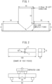
- FIG. 1 is a view showing a finite element method analysis model for estimating a bending stress occurring at a rectangular tooth shape.
- the analysis model was a two-dimensional model in the planar distortion state.
- two root corners at a width 10 mm, height 10 mm rectangular tooth shape were smoothly connected by arcs with a radius of curvature p to obtain an elastic member with a vertical modulus of elasticity of 213 GPa and a Poisson ratio of 0.3. This was divided into square elements.
- the bottom side was completely fixed and displacement of 0.05 mm was given in the left direction to the top right corner at the rectangular tooth shape.
- the radius of curvature p was made three levels of 0.3 mm, 1 mm, and 3 mm.
- the average concentration of N of the surface layer part is 5000 ppm or more. Due to this, the effect is obtained that a large amount of nitrides precipitate and the surface layer part is improved in hardness and in turn the nitrided part can be raised in fatigue strength.
- the "surface layer part” means the part of the region in the range of the surface of the nitrided part down to 200 ⁇ m in the depth direction.
- the average concentration of N can be measured by the following method. That is, first, the part is cut vertically to the surface to obtain a measurement sample. The observed surface is polished to a mirror finish. After that, the concentration of N in the range from the surface down to 200 ⁇ m in the depth direction (that is, the surface layer part) is measured in the depth direction at 0.5 ⁇ m pitches by an electron probe microanalyzer (EPMA) and the average concentration of N is calculated.
- EPMA electron probe microanalyzer
- the nitrided part of the present invention having a predetermined chemical composition and having structures, an aspect ratio of the ferrite grains, regions of presence of elongated ferrite grains, and an average concentration of N of the surface layer part all satisfying predetermined ranges, it is possible to realize excellent fatigue strength along with the above-mentioned effects.
- the method of producing the nitrided part of the present embodiment includes at least a hot rolling step, cold working step, and nitriding step.
- a steel material is obtained from cast steel adjusted to a chemical composition corresponding to the chemical composition of the above-mentioned nitrided part. Further, this steel material is used for hot rolling.
- the final stand exit temperature of the steel material is made 1050°C or more. Due to this, all of the V contained is made the solid solution state.
- the steel After hot rolling, the steel is immediately cooled in the atmosphere or air-cooled. Specifically, the average cooling rate between 900 to 500°C is made 0.4°C/s or more to inhibit the precipitation of VC. Further, by making the average cooling rate between 900°C to 500°C 2.0°C/s or less, it is possible to prevent the formation of bainite. For this reason, the structures of the steel material cooled by this cooling rate condition and in turn the structures of the nitrided part become structures consisting of ferrite and pearlite.
- the steel material hot rolled as explained above is then formed with a predetermined lubrication film for use for cold working.
- a predetermined lubrication film for use for cold working. Note that, below, an example will be given of use of cold forging, in particular, in cold working.
- VC precipitates. This VC ends up lowering the effect of inhibition of the recovery and recrystallization of the elongated grains due to the solid solution V at the time of nitriding intended by the present embodiment. Due to the above reasons, no annealing is performed before the cold forging in the present embodiment.
- parts are formed by cold forging.
- the cold forging is performed to raise the degree of working of part where stress is expected to concentrate where stress concentrates at the time when the nitrided part is actually used.
- the "part where stress is expected to concentrate” is the part where it is expected that a large stress will be applied during operation in the nitrided part. In general, it is the portion with a small curvature.
- the boundary between the boss and flange in a flange with a boss, the bottom of teeth of the gear, and portions where stress concentrates in the same way as these may be mentioned as parts where stress is expected to concentrate.
- the aspect ratio of the ratio of the lengths in the long axis direction and short axial direction of the ferrite grains is made to become 4.5 or more at the entire region at a depth of ( ⁇ 0.09+0.05) mm or less from the surface of the part where stress is expected to concentrate (p: radius of curvature of part where stress is expected to concentrate (mm)). Due to this, suitable predetermined ferrite elongated grains can be obtained even after the later explained nitriding.
- the part obtained by cold working (cold forging) as explained above is then used for nitriding.
- the nitriding in the present embodiment may be treatment under any conditions so long as treatment whereby the average concentration of N of the surface layer part from the surface of the nitrided part down to 200 ⁇ m in the depth direction becomes 5000 ppm or more.
- a predetermined amount of V is made to form a solid solution in the steel material, even if nitriding in this way, no recrystallized grains are formed, the elongated grains formed by cold working are maintained, and ferrite grains with an aspect ratio of a ratio of the long axis direction and short axis direction of 4.5 or more can be made present in the nitrided part.
- the combination of the above-mentioned effects enables a nitrided part having an excellent fatigue strength to be obtained.
- Test Pieces "a” to “h” and “l” to “s” were all judged to have low hardnesses after rolling of less than 170HV and to be excellent in cold workability. Conversely, the Test Pieces "i” to “k” were all judged to have high hardnesses after rolling of 170HV or more and to be inferior in cold workability.
- Hot Rolled Steel Bars “a” to “o” and Hot Rolled Steel Bars “q” to “s” were formed with notches by cold forging, while the Hot Rolled Steel Bar “p” was formed with a notch by machining.
- test pieces were cut out from the hot rolled steel bars and predetermined lubrication coatings were formed. After that, the test pieces were cold forged by punching by a plate-shaped punch of a width 4 mm, height 10 mm, and depth 40 mm with edge parts at the bottom surface rounded by a radius of curvature of 2 mm. Note that, the amount of punching by the plate-shaped punch was as shown in Table 2.
- test pieces were finished by machining based on the notches to end the formation of the notches.
- the Test Piece "r” was finished by machining based on the notch cut deeper by 0.5 mm by machining so as to make the depth of the region where elongated grains with an aspect ratio of 4.5 or more were formed 0.15 mm.
- the Test Piece "s” was finished by machining based on the notch cut deeper by 0.4 mm depth by machining so as to make the depth of the region where elongated grains with an aspect ratio of 4.5 or more were formed 0.25 mm.
- the bottom of the notch was the part where stress concentrated in the subsequent four point bending fatigue test.
- the radius of curvature of the notch was 2 mm, so the depth "d" at which a high bending stress occurred of 0.8 time or more the bending stress of the surface-most part became 0.23 mm.
- Test Pieces "a” to "s” were nitrided.
- the nitriding in each case was performed at 570°C for 5 hours.
- the nitriding potential Kn was made 0.6 and oil quenching was performed at 90°C.
- the nitrided part obtained in the above way was investigated for (I) whether the structures consisted of ferrite and pearlite, (II) whether ferrite grains with an aspect ratio of the ratio of the long axis direction and short axis direction of 4.5 or more were present in the entire region at a depth of 0.23 mm from the surface of the bottom of the notch, and (III) average concentration of N (ppm) of the surface layer part from the surface down to 200 ⁇ m in the depth direction and was investigated for (IV) the fatigue life of a four point bending test (cycles) at a maximum load of 12 kN. The results are shown in Table 3.
- the average aspect ratio of the elongated grains at the surface layer part was calculated by cutting out any cross-section at the surface layer part, picking out ferrite grains able to be seen on this cut cross-section at 20 points, measuring the aspect ratio of the ferrite grains, then finding their average. Note that, Samples "a” to “l”, “n”, and “o” were difficult to measure for aspect ratio by an optical microscope, so the aspect ratio was calculated from the amount of strain found by finite element method analysis.
- FIG. 2 is a view showing a shape of a four-point bending fatigue test piece and a load in a four test point bending fatigue test.
- a 13 mm square cross-section ⁇ 100 mm length test piece was formed as explained above by cold forging and machining (Samples “a” to “o” and “q” to “s”) or machining (Sample "p").
- a lower side supporting point was placed at the 80 mm position and the upper side supporting point was placed at the 20 mm position sandwiching a notch with a radius of curvature of 2 mm formed at the center point of length of the test piece and a repeated load was applied to the upper side supporting point.
- a 10 tonf Servopulsar made by Shimadzu Corporation was used.
- a 12 kN load was repeatedly applied at 10Hz and the fatigue test life (number of repetitions required for breaking test piece) was investigated. At this time, the minimum load was set to 0.6 kN corresponding to 5% of the maximum load of 12 kN.
Landscapes
- Chemical & Material Sciences (AREA)
- Engineering & Computer Science (AREA)
- Mechanical Engineering (AREA)
- Materials Engineering (AREA)
- Metallurgy (AREA)
- Organic Chemistry (AREA)
- Chemical Kinetics & Catalysis (AREA)
- Physics & Mathematics (AREA)
- Thermal Sciences (AREA)
- Crystallography & Structural Chemistry (AREA)
- Manufacturing & Machinery (AREA)
- Heat Treatment Of Steel (AREA)
- Solid-Phase Diffusion Into Metallic Material Surfaces (AREA)
Claims (6)
- Pièce nitrurée comprenant, en % en masse, C: 0,05 à 0,20 %, Si: 0,05 à 0,20 %, Mn: 0,20 à 0,50 %, P: 0,030 % ou moins, S: 0,020 % ou moins, et V: 0,10 à 0,50 %, comprenant éventuellement en outre, en % en masse, au moins un élément choisi dans le groupe consistant en Mo: 0,10 à 0,50 % et Nb: 0,01 à 0,05 %, et/ou au moins un élément choisi dans le groupe consistant en Cr: 0,1 à 2,0 % et Al: 0,01 à 0,1 %, et ayant un solde de Fe et d'impuretés inévitables,ayant des structures consistant en ferrite et perlite,ayant des grains de ferrite ayant un rapport d'aspect d'un rapport d'une direction d'axe long et d'une direction d'axe court de 4,5 ou plus présents dans une région entière à une profondeur de (ρ × 0,09 + 0,05) mm ou moins à partir d'une surface d'une partie où il est prévu qu'une contrainte se concentre, etayant une concentration moyenne de N de 5000 ppm ou plus au niveau d'une partie de couche superficielle à partir d'une surface jusqu'à 200 µm dans une direction de la profondeur:où ρ est un rayon de courbure en mm de la partie où il est prévu qu'une contrainte se concentre,dans laquelle le rapport d'aspect et la concentration moyenne de N sont déterminés conformément à la description.
- Pièce nitrurée selon la revendication 1, comprenant, en % en masse, au moins un élément choisi dans le groupe consistant en Mo: 0,10 à 0,50 % et Nb: 0,01 à 0,05 %.
- Pièce nitrurée selon la revendication 1 ou 2, comprenant, en % en masse, au moins un élément choisi dans le groupe consistant en Cr: 0,1 à 2,0 % et Al: 0,01 à 0,1%.
- Procédé de production de la pièce nitrurée selon l'une quelconque des revendications 1 à 3 comprenant:une étape de laminage à chaud à une température de sortie de cage finale de 1050°C ou plus d'un matériau en acier d'une composition comprenant, en % en masse, C: 0,05 à 0,20 %, Si: 0,05 à 0,20 %, Mn: 0,20 à 0,50 %, P: 0,030 % ou moins, S: 0,020 % ou moins, et V: 0,10 à 0,50 %, comprenant éventuellement en outre, en % en masse, au moins un élément choisi dans le groupe consistant en Mo: 0,10 à 0,50 % et Nb: 0,01 à 0,05%, et/ou au moins un élément choisi dans le groupe consistant en Cr: 0,1 à 2,0 % et Al: 0,01 à 0,1 %, et ayant un solde de Fe et d'impuretés inévitables, et de refroidissement du matériau en acier entre 900°C et 500°C à raison de 0,4 à 2,0°C/s,une étape de travail à froid du matériau en acier, sans recuit, de sorte qu'un rapport d'aspect d'un rapport d'une direction d'axe long et d'une direction d'axe court de grains de ferrite devient 4,5 ou plus dans une région entière avec une profondeur de (ρ × 0,09 + 0,05) mm ou moins à partir d'une surface d'une partie où il est prévu qu'une contrainte se concentre, etune étape de nitruration:
où ρ est un rayon de courbure en mm d'une partie où il est prévu qu'une contrainte se concentre. - Procédé de production d'une pièce nitrurée selon la revendication 4, dans lequel le matériau en acier comprend, en % en masse, au moins un élément choisi dans le groupe consistant en Mo: 0,10 à 0,50 % et Nb: 0,01 à 0,05 %.
- Procédé de production d'une pièce nitrurée selon la revendication 4 ou 5, dans lequel le matériau en acier comprend, en % en masse, au moins un élément choisi dans le groupe consistant en Cr: 0,1 à 2,0 % et Al: 0,01 à 0,1%.
Applications Claiming Priority (2)
| Application Number | Priority Date | Filing Date | Title |
|---|---|---|---|
| JP2017029144 | 2017-02-20 | ||
| PCT/JP2018/006051 WO2018151321A1 (fr) | 2017-02-20 | 2018-02-20 | Composant nitruré et son procédé de fabrication |
Publications (3)
| Publication Number | Publication Date |
|---|---|
| EP3584343A1 EP3584343A1 (fr) | 2019-12-25 |
| EP3584343A4 EP3584343A4 (fr) | 2020-11-11 |
| EP3584343B1 true EP3584343B1 (fr) | 2024-09-25 |
Family
ID=63170325
Family Applications (1)
| Application Number | Title | Priority Date | Filing Date |
|---|---|---|---|
| EP18754123.0A Active EP3584343B1 (fr) | 2017-02-20 | 2018-02-20 | Pièce nitrurée et son procédé de production |
Country Status (4)
| Country | Link |
|---|---|
| US (1) | US10837097B2 (fr) |
| EP (1) | EP3584343B1 (fr) |
| JP (1) | JP6822548B2 (fr) |
| WO (1) | WO2018151321A1 (fr) |
Families Citing this family (3)
| Publication number | Priority date | Publication date | Assignee | Title |
|---|---|---|---|---|
| JP7800789B1 (ja) * | 2024-08-23 | 2026-01-16 | Jfeスチール株式会社 | 鋼および鋼部品 |
| WO2026042642A1 (fr) * | 2024-08-23 | 2026-02-26 | Jfeスチール株式会社 | Acier et composant d'acier |
| WO2026042643A1 (fr) * | 2024-08-23 | 2026-02-26 | Jfeスチール株式会社 | Acier, composant d'acier et procédé de fabrication d'acier |
Family Cites Families (9)
| Publication number | Priority date | Publication date | Assignee | Title |
|---|---|---|---|---|
| JPH05171347A (ja) * | 1991-12-18 | 1993-07-09 | Aichi Steel Works Ltd | 冷間鍛造性に優れた軟窒化用鋼 |
| JPH09279295A (ja) | 1996-04-16 | 1997-10-28 | Nippon Steel Corp | 冷間鍛造性に優れた軟窒化用鋼 |
| KR101401130B1 (ko) * | 2009-06-17 | 2014-05-29 | 신닛테츠스미킨 카부시키카이샤 | 질화용 강 및 질화 처리 부품 |
| JP5617747B2 (ja) | 2010-07-16 | 2014-11-05 | 新日鐵住金株式会社 | 窒化処理機械部品の製造方法 |
| JP5521970B2 (ja) * | 2010-10-20 | 2014-06-18 | 新日鐵住金株式会社 | 冷鍛窒化用鋼、冷鍛窒化用鋼材および冷鍛窒化部品 |
| JP5597563B2 (ja) * | 2011-02-01 | 2014-10-01 | 新日鐵住金株式会社 | 窒化用鋼および窒化部品 |
| JP5682486B2 (ja) * | 2011-07-07 | 2015-03-11 | 新日鐵住金株式会社 | 冷鍛窒化用鋼材 |
| JP5768734B2 (ja) * | 2012-02-02 | 2015-08-26 | 新日鐵住金株式会社 | 冷鍛窒化用圧延鋼材 |
| JP5783101B2 (ja) * | 2012-03-22 | 2015-09-24 | 新日鐵住金株式会社 | 窒化用鋼材 |
-
2018
- 2018-02-20 US US16/486,999 patent/US10837097B2/en not_active Expired - Fee Related
- 2018-02-20 EP EP18754123.0A patent/EP3584343B1/fr active Active
- 2018-02-20 JP JP2019500191A patent/JP6822548B2/ja active Active
- 2018-02-20 WO PCT/JP2018/006051 patent/WO2018151321A1/fr not_active Ceased
Also Published As
| Publication number | Publication date |
|---|---|
| JP6822548B2 (ja) | 2021-01-27 |
| EP3584343A4 (fr) | 2020-11-11 |
| JPWO2018151321A1 (ja) | 2019-11-21 |
| US10837097B2 (en) | 2020-11-17 |
| US20200024721A1 (en) | 2020-01-23 |
| WO2018151321A1 (fr) | 2018-08-23 |
| EP3584343A1 (fr) | 2019-12-25 |
Similar Documents
| Publication | Publication Date | Title |
|---|---|---|
| EP3088550B1 (fr) | Procédé de production de constituant en acier cémenté et constituant en acier cémenté | |
| EP2415891A1 (fr) | Tôle d'acier laminée à froid et son procédé de fabrication | |
| JP5123335B2 (ja) | クランクシャフトおよびその製造方法 | |
| US11542569B2 (en) | Austenitic stainless steel having excellent processability and surface characteristics, and manufacturing method therefor | |
| US20180066344A1 (en) | Wire rod for use in bolts that has excellent acid pickling properties and resistance to delayed fracture after quenching and tempering, and bolt | |
| EP3489381A1 (fr) | Acier pour durcissement par induction | |
| EP3741879B1 (fr) | Tôle en acier laminée à froid à haut carbone, et procédé de fabrication de celle-ci | |
| EP3584343B1 (fr) | Pièce nitrurée et son procédé de production | |
| EP3489378A1 (fr) | Acier pour trempe par induction | |
| EP3489379A1 (fr) | Acier pour trempe par induction | |
| JP3460659B2 (ja) | 軟質で熱処理歪みの小さい高炭素鋼帯とその製造方法 | |
| CN116888293B (zh) | 冷加工用机械结构用钢及其制造方法 | |
| US20140230968A1 (en) | Maraging steel | |
| US10428414B2 (en) | Carburized component | |
| JP2010189697A (ja) | クランクシャフトおよびその製造方法 | |
| JP6690464B2 (ja) | 浸炭部品 | |
| EP3272896B1 (fr) | Acier durcissable par vieillissement, et procédé de fabrication de composants au moyen de l'acier durcissable par vieillissement | |
| US10689721B2 (en) | Case hardening steel and carburized component obtained therefrom | |
| US10287668B2 (en) | Case hardening steel | |
| EP4177368A1 (fr) | Acier inoxydable austénitique présentant une aptitude à l'emboutissage profond améliorée | |
| JP7829992B2 (ja) | 芯部硬さに優れた窒化用鋼 | |
| WO2024171976A1 (fr) | Acier pour forgeage à froid/nitruration ayant une excellente aptitude au forgeage à froid et d'excellentes propriétés de nitruration, et composant forgé à froid/nitruré l'utilisant | |
| EP2803745A1 (fr) | Tôle d'acier laminée à chaud et son procédé de fabrication | |
| JP3888288B2 (ja) | 異形引抜きと高周波焼入れを施して用いる鋼材及びそれを用いた鋼部材の製造法 | |
| TWI883700B (zh) | 熱軋鋼材及其製造方法 |
Legal Events
| Date | Code | Title | Description |
|---|---|---|---|
| STAA | Information on the status of an ep patent application or granted ep patent |
Free format text: STATUS: THE INTERNATIONAL PUBLICATION HAS BEEN MADE |
|
| PUAI | Public reference made under article 153(3) epc to a published international application that has entered the european phase |
Free format text: ORIGINAL CODE: 0009012 |
|
| STAA | Information on the status of an ep patent application or granted ep patent |
Free format text: STATUS: REQUEST FOR EXAMINATION WAS MADE |
|
| 17P | Request for examination filed |
Effective date: 20190913 |
|
| AK | Designated contracting states |
Kind code of ref document: A1 Designated state(s): AL AT BE BG CH CY CZ DE DK EE ES FI FR GB GR HR HU IE IS IT LI LT LU LV MC MK MT NL NO PL PT RO RS SE SI SK SM TR |
|
| AX | Request for extension of the european patent |
Extension state: BA ME |
|
| DAV | Request for validation of the european patent (deleted) | ||
| DAX | Request for extension of the european patent (deleted) | ||
| A4 | Supplementary search report drawn up and despatched |
Effective date: 20201009 |
|
| RIC1 | Information provided on ipc code assigned before grant |
Ipc: C22C 38/06 20060101ALI20201005BHEP Ipc: B21K 1/30 20060101ALI20201005BHEP Ipc: C22C 38/02 20060101ALI20201005BHEP Ipc: C21D 8/06 20060101ALI20201005BHEP Ipc: C22C 38/24 20060101ALI20201005BHEP Ipc: C21D 1/06 20060101ALI20201005BHEP Ipc: C22C 38/22 20060101ALI20201005BHEP Ipc: C23C 8/02 20060101ALI20201005BHEP Ipc: B21J 5/00 20060101ALI20201005BHEP Ipc: C22C 38/00 20060101AFI20201005BHEP Ipc: C22C 38/04 20060101ALI20201005BHEP Ipc: C23C 8/26 20060101ALI20201005BHEP Ipc: B21J 1/06 20060101ALI20201005BHEP Ipc: C22C 38/26 20060101ALI20201005BHEP Ipc: C21D 9/32 20060101ALI20201005BHEP Ipc: C22C 38/12 20060101ALI20201005BHEP |
|
| GRAP | Despatch of communication of intention to grant a patent |
Free format text: ORIGINAL CODE: EPIDOSNIGR1 |
|
| STAA | Information on the status of an ep patent application or granted ep patent |
Free format text: STATUS: GRANT OF PATENT IS INTENDED |
|
| INTG | Intention to grant announced |
Effective date: 20240422 |
|
| GRAS | Grant fee paid |
Free format text: ORIGINAL CODE: EPIDOSNIGR3 |
|
| GRAA | (expected) grant |
Free format text: ORIGINAL CODE: 0009210 |
|
| STAA | Information on the status of an ep patent application or granted ep patent |
Free format text: STATUS: THE PATENT HAS BEEN GRANTED |
|
| AK | Designated contracting states |
Kind code of ref document: B1 Designated state(s): AL AT BE BG CH CY CZ DE DK EE ES FI FR GB GR HR HU IE IS IT LI LT LU LV MC MK MT NL NO PL PT RO RS SE SI SK SM TR |
|
| REG | Reference to a national code |
Ref country code: GB Ref legal event code: FG4D |
|
| REG | Reference to a national code |
Ref country code: CH Ref legal event code: EP |
|
| REG | Reference to a national code |
Ref country code: DE Ref legal event code: R096 Ref document number: 602018074718 Country of ref document: DE |
|
| REG | Reference to a national code |
Ref country code: IE Ref legal event code: FG4D |
|
| REG | Reference to a national code |
Ref country code: LT Ref legal event code: MG9D |
|
| PG25 | Lapsed in a contracting state [announced via postgrant information from national office to epo] |
Ref country code: NO Free format text: LAPSE BECAUSE OF FAILURE TO SUBMIT A TRANSLATION OF THE DESCRIPTION OR TO PAY THE FEE WITHIN THE PRESCRIBED TIME-LIMIT Effective date: 20241225 |
|
| PG25 | Lapsed in a contracting state [announced via postgrant information from national office to epo] |
Ref country code: GR Free format text: LAPSE BECAUSE OF FAILURE TO SUBMIT A TRANSLATION OF THE DESCRIPTION OR TO PAY THE FEE WITHIN THE PRESCRIBED TIME-LIMIT Effective date: 20241226 Ref country code: FI Free format text: LAPSE BECAUSE OF FAILURE TO SUBMIT A TRANSLATION OF THE DESCRIPTION OR TO PAY THE FEE WITHIN THE PRESCRIBED TIME-LIMIT Effective date: 20240925 |
|
| PG25 | Lapsed in a contracting state [announced via postgrant information from national office to epo] |
Ref country code: BG Free format text: LAPSE BECAUSE OF FAILURE TO SUBMIT A TRANSLATION OF THE DESCRIPTION OR TO PAY THE FEE WITHIN THE PRESCRIBED TIME-LIMIT Effective date: 20240925 |
|
| PG25 | Lapsed in a contracting state [announced via postgrant information from national office to epo] |
Ref country code: LV Free format text: LAPSE BECAUSE OF FAILURE TO SUBMIT A TRANSLATION OF THE DESCRIPTION OR TO PAY THE FEE WITHIN THE PRESCRIBED TIME-LIMIT Effective date: 20240925 |
|
| PG25 | Lapsed in a contracting state [announced via postgrant information from national office to epo] |
Ref country code: RS Free format text: LAPSE BECAUSE OF FAILURE TO SUBMIT A TRANSLATION OF THE DESCRIPTION OR TO PAY THE FEE WITHIN THE PRESCRIBED TIME-LIMIT Effective date: 20241225 |
|
| REG | Reference to a national code |
Ref country code: NL Ref legal event code: MP Effective date: 20240925 |
|
| PG25 | Lapsed in a contracting state [announced via postgrant information from national office to epo] |
Ref country code: RS Free format text: LAPSE BECAUSE OF FAILURE TO SUBMIT A TRANSLATION OF THE DESCRIPTION OR TO PAY THE FEE WITHIN THE PRESCRIBED TIME-LIMIT Effective date: 20241225 Ref country code: NO Free format text: LAPSE BECAUSE OF FAILURE TO SUBMIT A TRANSLATION OF THE DESCRIPTION OR TO PAY THE FEE WITHIN THE PRESCRIBED TIME-LIMIT Effective date: 20241225 Ref country code: LV Free format text: LAPSE BECAUSE OF FAILURE TO SUBMIT A TRANSLATION OF THE DESCRIPTION OR TO PAY THE FEE WITHIN THE PRESCRIBED TIME-LIMIT Effective date: 20240925 Ref country code: GR Free format text: LAPSE BECAUSE OF FAILURE TO SUBMIT A TRANSLATION OF THE DESCRIPTION OR TO PAY THE FEE WITHIN THE PRESCRIBED TIME-LIMIT Effective date: 20241226 Ref country code: FI Free format text: LAPSE BECAUSE OF FAILURE TO SUBMIT A TRANSLATION OF THE DESCRIPTION OR TO PAY THE FEE WITHIN THE PRESCRIBED TIME-LIMIT Effective date: 20240925 Ref country code: BG Free format text: LAPSE BECAUSE OF FAILURE TO SUBMIT A TRANSLATION OF THE DESCRIPTION OR TO PAY THE FEE WITHIN THE PRESCRIBED TIME-LIMIT Effective date: 20240925 |
|
| REG | Reference to a national code |
Ref country code: AT Ref legal event code: MK05 Ref document number: 1726685 Country of ref document: AT Kind code of ref document: T Effective date: 20240925 |
|
| PG25 | Lapsed in a contracting state [announced via postgrant information from national office to epo] |
Ref country code: NL Free format text: LAPSE BECAUSE OF FAILURE TO SUBMIT A TRANSLATION OF THE DESCRIPTION OR TO PAY THE FEE WITHIN THE PRESCRIBED TIME-LIMIT Effective date: 20240925 |
|
| PG25 | Lapsed in a contracting state [announced via postgrant information from national office to epo] |
Ref country code: PT Free format text: LAPSE BECAUSE OF FAILURE TO SUBMIT A TRANSLATION OF THE DESCRIPTION OR TO PAY THE FEE WITHIN THE PRESCRIBED TIME-LIMIT Effective date: 20250127 Ref country code: IS Free format text: LAPSE BECAUSE OF FAILURE TO SUBMIT A TRANSLATION OF THE DESCRIPTION OR TO PAY THE FEE WITHIN THE PRESCRIBED TIME-LIMIT Effective date: 20250125 |
|
| PG25 | Lapsed in a contracting state [announced via postgrant information from national office to epo] |
Ref country code: RO Free format text: LAPSE BECAUSE OF FAILURE TO SUBMIT A TRANSLATION OF THE DESCRIPTION OR TO PAY THE FEE WITHIN THE PRESCRIBED TIME-LIMIT Effective date: 20240925 Ref country code: SM Free format text: LAPSE BECAUSE OF FAILURE TO SUBMIT A TRANSLATION OF THE DESCRIPTION OR TO PAY THE FEE WITHIN THE PRESCRIBED TIME-LIMIT Effective date: 20240925 |
|
| PG25 | Lapsed in a contracting state [announced via postgrant information from national office to epo] |
Ref country code: ES Free format text: LAPSE BECAUSE OF FAILURE TO SUBMIT A TRANSLATION OF THE DESCRIPTION OR TO PAY THE FEE WITHIN THE PRESCRIBED TIME-LIMIT Effective date: 20240925 |
|
| PG25 | Lapsed in a contracting state [announced via postgrant information from national office to epo] |
Ref country code: EE Free format text: LAPSE BECAUSE OF FAILURE TO SUBMIT A TRANSLATION OF THE DESCRIPTION OR TO PAY THE FEE WITHIN THE PRESCRIBED TIME-LIMIT Effective date: 20240925 Ref country code: AT Free format text: LAPSE BECAUSE OF FAILURE TO SUBMIT A TRANSLATION OF THE DESCRIPTION OR TO PAY THE FEE WITHIN THE PRESCRIBED TIME-LIMIT Effective date: 20240925 |
|
| PG25 | Lapsed in a contracting state [announced via postgrant information from national office to epo] |
Ref country code: CZ Free format text: LAPSE BECAUSE OF FAILURE TO SUBMIT A TRANSLATION OF THE DESCRIPTION OR TO PAY THE FEE WITHIN THE PRESCRIBED TIME-LIMIT Effective date: 20240925 Ref country code: PL Free format text: LAPSE BECAUSE OF FAILURE TO SUBMIT A TRANSLATION OF THE DESCRIPTION OR TO PAY THE FEE WITHIN THE PRESCRIBED TIME-LIMIT Effective date: 20240925 |
|
| PG25 | Lapsed in a contracting state [announced via postgrant information from national office to epo] |
Ref country code: IT Free format text: LAPSE BECAUSE OF FAILURE TO SUBMIT A TRANSLATION OF THE DESCRIPTION OR TO PAY THE FEE WITHIN THE PRESCRIBED TIME-LIMIT Effective date: 20240925 Ref country code: SK Free format text: LAPSE BECAUSE OF FAILURE TO SUBMIT A TRANSLATION OF THE DESCRIPTION OR TO PAY THE FEE WITHIN THE PRESCRIBED TIME-LIMIT Effective date: 20240925 |
|
| REG | Reference to a national code |
Ref country code: DE Ref legal event code: R097 Ref document number: 602018074718 Country of ref document: DE |
|
| PG25 | Lapsed in a contracting state [announced via postgrant information from national office to epo] |
Ref country code: DK Free format text: LAPSE BECAUSE OF FAILURE TO SUBMIT A TRANSLATION OF THE DESCRIPTION OR TO PAY THE FEE WITHIN THE PRESCRIBED TIME-LIMIT Effective date: 20240925 |
|
| PLBE | No opposition filed within time limit |
Free format text: ORIGINAL CODE: 0009261 |
|
| STAA | Information on the status of an ep patent application or granted ep patent |
Free format text: STATUS: NO OPPOSITION FILED WITHIN TIME LIMIT |
|
| 26N | No opposition filed |
Effective date: 20250626 |
|
| PG25 | Lapsed in a contracting state [announced via postgrant information from national office to epo] |
Ref country code: SE Free format text: LAPSE BECAUSE OF FAILURE TO SUBMIT A TRANSLATION OF THE DESCRIPTION OR TO PAY THE FEE WITHIN THE PRESCRIBED TIME-LIMIT Effective date: 20240925 |
|
| PG25 | Lapsed in a contracting state [announced via postgrant information from national office to epo] |
Ref country code: MC Free format text: LAPSE BECAUSE OF FAILURE TO SUBMIT A TRANSLATION OF THE DESCRIPTION OR TO PAY THE FEE WITHIN THE PRESCRIBED TIME-LIMIT Effective date: 20240925 |
|
| REG | Reference to a national code |
Ref country code: CH Ref legal event code: PL |
|
| PG25 | Lapsed in a contracting state [announced via postgrant information from national office to epo] |
Ref country code: LU Free format text: LAPSE BECAUSE OF NON-PAYMENT OF DUE FEES Effective date: 20250220 |
|
| PG25 | Lapsed in a contracting state [announced via postgrant information from national office to epo] |
Ref country code: CH Free format text: LAPSE BECAUSE OF NON-PAYMENT OF DUE FEES Effective date: 20250228 |
|
| GBPC | Gb: european patent ceased through non-payment of renewal fee |
Effective date: 20250220 |
|
| REG | Reference to a national code |
Ref country code: BE Ref legal event code: MM Effective date: 20250228 |
|
| PG25 | Lapsed in a contracting state [announced via postgrant information from national office to epo] |
Ref country code: GB Free format text: LAPSE BECAUSE OF NON-PAYMENT OF DUE FEES Effective date: 20250220 |
|
| PG25 | Lapsed in a contracting state [announced via postgrant information from national office to epo] |
Ref country code: HR Free format text: LAPSE BECAUSE OF FAILURE TO SUBMIT A TRANSLATION OF THE DESCRIPTION OR TO PAY THE FEE WITHIN THE PRESCRIBED TIME-LIMIT Effective date: 20240925 Ref country code: FR Free format text: LAPSE BECAUSE OF NON-PAYMENT OF DUE FEES Effective date: 20250228 |
|
| PG25 | Lapsed in a contracting state [announced via postgrant information from national office to epo] |
Ref country code: BE Free format text: LAPSE BECAUSE OF NON-PAYMENT OF DUE FEES Effective date: 20250228 |
|
| PG25 | Lapsed in a contracting state [announced via postgrant information from national office to epo] |
Ref country code: IE Free format text: LAPSE BECAUSE OF NON-PAYMENT OF DUE FEES Effective date: 20250220 |
|
| PGFP | Annual fee paid to national office [announced via postgrant information from national office to epo] |
Ref country code: DE Payment date: 20251230 Year of fee payment: 9 |