EP3584367A1 - Anordnung einer verbindungsvorrichtung - Google Patents
Anordnung einer verbindungsvorrichtung Download PDFInfo
- Publication number
- EP3584367A1 EP3584367A1 EP18020262.4A EP18020262A EP3584367A1 EP 3584367 A1 EP3584367 A1 EP 3584367A1 EP 18020262 A EP18020262 A EP 18020262A EP 3584367 A1 EP3584367 A1 EP 3584367A1
- Authority
- EP
- European Patent Office
- Prior art keywords
- retaining plate
- concrete
- face
- retaining
- window
- Prior art date
- Legal status (The legal status is an assumption and is not a legal conclusion. Google has not performed a legal analysis and makes no representation as to the accuracy of the status listed.)
- Granted
Links
Images


Classifications
-
- E—FIXED CONSTRUCTIONS
- E01—CONSTRUCTION OF ROADS, RAILWAYS, OR BRIDGES
- E01C—CONSTRUCTION OF, OR SURFACES FOR, ROADS, SPORTS GROUNDS, OR THE LIKE; MACHINES OR AUXILIARY TOOLS FOR CONSTRUCTION OR REPAIR
- E01C11/00—Details of pavings
- E01C11/02—Arrangement or construction of joints; Methods of making joints; Packing for joints
- E01C11/04—Arrangement or construction of joints; Methods of making joints; Packing for joints for cement concrete paving
- E01C11/14—Dowel assembly ; Design or construction of reinforcements in the area of joints
-
- E—FIXED CONSTRUCTIONS
- E01—CONSTRUCTION OF ROADS, RAILWAYS, OR BRIDGES
- E01C—CONSTRUCTION OF, OR SURFACES FOR, ROADS, SPORTS GROUNDS, OR THE LIKE; MACHINES OR AUXILIARY TOOLS FOR CONSTRUCTION OR REPAIR
- E01C11/00—Details of pavings
- E01C11/02—Arrangement or construction of joints; Methods of making joints; Packing for joints
- E01C11/04—Arrangement or construction of joints; Methods of making joints; Packing for joints for cement concrete paving
- E01C11/12—Packing of metal and plastic or elastic materials
Definitions
- connection devices are known between two concrete bodies.
- connection device comprising a retaining plate comprising clip fingers for fixing bars of a metal frame.
- Clipping requires a fairly significant effort.
- this clipping is only possible after fixing the socket on the retaining plate. Therefore, if the socket is not prefixed, it is necessary to remove the retaining plate from the formwork wall, this to avoid any displacement of the retaining plate when sliding the socket support along the plate of restraint.
- the withdrawal of the latter is not easy and may cause the retaining plate to be torn away from the formwork wall.
- connection device with a socket integral with a folded sheet with a curved end. Correct filling of concrete between the sleeve and the sheet is not easy. Fixing the sleeve and bent sheet assembly to a formwork wall and frame is not easy, in particular because of the total weight of the assembly to be fixed.
- connection device comprising an assembly formed by a folded sheet welded to rebar and integral with a socket. Attaching this assembly to a wall is not easy.
- the invention relates to an assembly of a connection device allowing easy attachment of the assembly to a formwork wall, while ensuring correct positioning of the reinforcement, as well as after setting the concrete excellent support of the reinforcement in the concrete body.
- a positioning error removal of the assembly is easy, which will encourage staff to correct the location of the assemblies.
- the bushing becomes damaged after positioning an assembly on a formwork wall or in the event of the use of an unsuitable bushing, the assembly allows easy replacement of the damaged or unsuitable bushing by another.
- the subject of the invention is an assembly as described in the first paragraph of this specification.
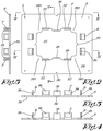
- the assembly according to the invention is essentially characterized in that the metal sheet (3C) of the first frame (3) is a folded metal sheet with a thickness of between 1.5 mm and 5mm having a substantially U-shaped part, the the core (3D) forms the flat face (3A) facing the expansion joint (J), said flat face (3A) having a retaining window (3F) cooperating with the retaining plate (5) of the sliding bushing (2) by a clipping system (6), while the retaining plate (5) of the sliding sleeve (2) cooperates with the support element (2A) of the sliding sleeve (2) by clipping system (7), and in that the retaining plate (5) of the sliding sleeve (2) has a flat face (5A) for bearing on a formwork wall (C) of the first concrete body (CB1), and openings (D ) for the passage of fixing means (8) of the plate retaining (5) on said formwork wall (C) of the first concrete body (
- This fixing by clipping allows easy disassembly of the assembly, for example in the event of incorrect positioning of the retaining plate or in the event of a defective part.
- the invention also relates to a concrete assembly comprising at least two concrete bodies, in particular two concrete plates, connected to each other by connection devices according to the invention cooperating with an intermediate expansion joint.
- the first object of the invention is a set (E) comprising at least the sliding bushing (2), the first metal frame (3), and the retaining plate (5) of the sliding bushing (2) allowing clipping independent of the socket on the retaining plate, the clipping of the first metal frame on the retaining plate, the clipping of the socket 2 and of the frame on the retaining plate cooperating to oppose an unwanted unclipping of the socket or frame relative to the retaining plate.
- the metal sheet (3C) of the first frame (3) is a folded metal sheet of thickness between 1.5 mm and 5mm having a substantially U-shaped part whose core (3D) forms the face flat (3A) facing the expansion joint (J), said flat face (3A) having a retaining window (3F) cooperating with the retaining plate (5) of the sliding sleeve (2) by a clipping system (6), while the retaining plate (5) of the sliding sleeve (2) cooperates with the support element (2A) of the sliding sleeve (2) by clipping system (7).
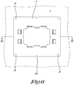
- the retaining plate (5) of the sliding sleeve (2) has a flat face (5A) for bearing on a formwork wall (C) of the first concrete body (CB1), and openings (D) for the passage of fastening means (8) of the retaining plate (5) on said formwork wall (C) of the first concrete body (CB1).
- the retaining window (3F) of the sheet (3C) of the first frame (3) has a shape with an outline (3G) cooperating with clipping lugs (6) of the retaining plate (5) extending along said second face (5B) of the retaining plate (5), while the retaining plate (5) has along its second face (5B) on the one hand, support zones (5B1) for the support element (2A) of the sliding sleeve (2), and, on the other hand, clip tabs (7) cooperating with edges or perimeter part (2A1) of the support element (2A) of the sliding sleeve (2).
- the clipping lugs (6) of the retaining plate (5) cooperating with the contour of the retaining window (3F) of the core (3D) of the folded metal sheet (3) include lugs cooperating with two parallel edges opposite (3F1,3F2) of the retaining window (3F).
- the clipping tabs (6) pass through the window 3F before being clipped.
- the retaining plate (5) has along its second face (5B) at least two stop tabs (5I, 5J) limiting in a direction parallel to said two opposite parallel edges (3F1.3F2) of the retaining window (3F ), a relative displacement between the retaining plate (5) and the core (3D) of the folded metal sheet (3).
- the stop tabs 5I, 5J pass through the window 3F of the folded sheet 3C.
- the stop tabs (5I, 5J) are clips for clipping the support element (2A) of the sliding bushing (2) onto the retaining plate (5).
- the support element 2A of the sleeve 2 is clipped onto the retaining plate (5), the support element is located in the volume of the window 3F of the folded sheet 3C.
- the support element 2A has a thickness substantially equal to that of the folded sheet 3C of the first frame 3.
- the retaining window (3F) is substantially rectangular defining a first pair of parallel edges (3F1.3F2) and a second pair of parallel edges (3F3.3F4).
- the retaining plate (5) comprises two or more of two clipping tabs ( 6) cooperating with each edge.
- the retaining plate comprises two or more of two clipping tabs cooperating with each of said edges of the retaining window.
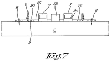
- the retaining plate has at least two stop tabs (7) extending along each edge of a pair of parallel edges (3F3,3F4), said stop tabs (7) acting as clipping tabs for the support element (2A) of the sliding sleeve (2), said stop tabs (7) being advantageously separated from one the other by a tab or centering means (18) cooperating with the support element (2A) of the sliding sleeve (2) to limit its relative displacement relative to the retaining plate (5).
- the retaining plate (5) has a window (5C) facing the retaining window (3F) of the bent sheet metal core (3D) when the retaining plate (5) is clipped onto the retaining window (3F).
- At least clipping lugs (7) and / or stop lugs or centering means (18) are formed along the periphery of the window (5C) of the retaining plate (5).
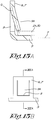
- Each clip tab (6,7) of the retaining plate is produced by folding a portion of the retaining plate (5) to form a tab extending substantially in a plane perpendicular to the plane (P) of the plate retaining (5), said tab having a cutout (9) to form a flap (9A) extending in a plane (Q) inclined relative to the plane (P) of the tab considered.
- the metal sheet folded in a U (3) has wings (3M, 3N) each having at least one window (3M1,3N1) for the passage of concrete and the evacuation of air, thus preventing the formation of air pockets at the structural level.
- the wings (3M, 3N) are connected to the core by a portion (3P, 3Q) partially curved and / or inclined having at least one window (3P1) for the passage of concrete and the evacuation of air, thus preventing the formation of air pockets at the level of the structure, when pouring concrete.
- the wings (3M, 3N) have an extreme portion of width (L3M, L3N) less than the width (L3D) of the core (3D). This width of the end part of the wings (3M, 3N) corresponds substantially to the distance separating the bars 13A, 13B from one another.
- the wings (3M, 3N) each have at least one flap (3M2.3N2) for fixing (for example by welding) the wing to a rod (13A, 13B) of the first frame (3).
- the flap or flaps may in embodiments form attachment means, for example clipping for part of the rod (13A, 13B).
- the support 2A of the socket 2 has a substantially rectangular outline with two recesses or recesses 2A2 for the placement of the stop or centering means 18 during the clipping, this limiting the movements of the support element 2A relative to the retaining plate .
- the frame 4 can be a frame similar to the frame 3, using an open socket, to maintain the position of the rod 1 on the frame 4, once one end of the rod is inserted into the socket sliding (2) clipped onto the retaining plate (5).
- the frame 4 can also be a frame of the type described in EP554483 .
- the steel sheet (3C) is removably mounted on the bars of the first frame (3), which for example has the form of two U-shaped bars connected to one another by welded sections. The steel sheet is then for example clipped onto the bars of the frame.
- the retaining plate advantageously includes positioning marks 50 to ensure correct positioning of the plate when it is fixed to a wall of a formwork.
Landscapes
- Engineering & Computer Science (AREA)
- Architecture (AREA)
- Civil Engineering (AREA)
- Structural Engineering (AREA)
- Forms Removed On Construction Sites Or Auxiliary Members Thereof (AREA)
- Joining Of Building Structures In Genera (AREA)
Priority Applications (1)
| Application Number | Priority Date | Filing Date | Title |
|---|---|---|---|
| EP18020262.4A EP3584367B1 (de) | 2018-06-18 | 2018-06-18 | Anordnung einer verbindungsvorrichtung |
Applications Claiming Priority (1)
| Application Number | Priority Date | Filing Date | Title |
|---|---|---|---|
| EP18020262.4A EP3584367B1 (de) | 2018-06-18 | 2018-06-18 | Anordnung einer verbindungsvorrichtung |
Publications (2)
| Publication Number | Publication Date |
|---|---|
| EP3584367A1 true EP3584367A1 (de) | 2019-12-25 |
| EP3584367B1 EP3584367B1 (de) | 2020-09-30 |
Family
ID=62705361
Family Applications (1)
| Application Number | Title | Priority Date | Filing Date |
|---|---|---|---|
| EP18020262.4A Active EP3584367B1 (de) | 2018-06-18 | 2018-06-18 | Anordnung einer verbindungsvorrichtung |
Country Status (1)
| Country | Link |
|---|---|
| EP (1) | EP3584367B1 (de) |
Cited By (1)
| Publication number | Priority date | Publication date | Assignee | Title |
|---|---|---|---|---|
| CN113482166A (zh) * | 2021-07-19 | 2021-10-08 | 合肥工业大学 | 剪力墙连接组件及剪力墙结构 |
Citations (4)
| Publication number | Priority date | Publication date | Assignee | Title |
|---|---|---|---|---|
| EP0113115A2 (de) | 1983-01-03 | 1984-07-11 | Coulter Systems Corporation | Elektrostatisches Bogentransportverfahren und Vorrichtung dazu |
| EP0554483A1 (de) | 1992-02-05 | 1993-08-11 | Claude Meyers | Verbindungs- und Druckverteilerelement für Betonbauteile |
| EP0773324A1 (de) | 1995-11-07 | 1997-05-14 | F.J. Aschwanden AG | Vorrichtung zum Verbinden und zur Aufnahme von Querkräften von zwei durch eine Fuge getrennten Bauteilen |
| EP1113115A2 (de) * | 1999-12-30 | 2001-07-04 | SCHÖCK BAUTEILE GmbH | Hülsen-/Dorn-Verbindung zwischen benachbarten Bauteilen |
-
2018
- 2018-06-18 EP EP18020262.4A patent/EP3584367B1/de active Active
Patent Citations (4)
| Publication number | Priority date | Publication date | Assignee | Title |
|---|---|---|---|---|
| EP0113115A2 (de) | 1983-01-03 | 1984-07-11 | Coulter Systems Corporation | Elektrostatisches Bogentransportverfahren und Vorrichtung dazu |
| EP0554483A1 (de) | 1992-02-05 | 1993-08-11 | Claude Meyers | Verbindungs- und Druckverteilerelement für Betonbauteile |
| EP0773324A1 (de) | 1995-11-07 | 1997-05-14 | F.J. Aschwanden AG | Vorrichtung zum Verbinden und zur Aufnahme von Querkräften von zwei durch eine Fuge getrennten Bauteilen |
| EP1113115A2 (de) * | 1999-12-30 | 2001-07-04 | SCHÖCK BAUTEILE GmbH | Hülsen-/Dorn-Verbindung zwischen benachbarten Bauteilen |
Cited By (2)
| Publication number | Priority date | Publication date | Assignee | Title |
|---|---|---|---|---|
| CN113482166A (zh) * | 2021-07-19 | 2021-10-08 | 合肥工业大学 | 剪力墙连接组件及剪力墙结构 |
| CN113482166B (zh) * | 2021-07-19 | 2023-08-11 | 合肥工业大学 | 剪力墙连接组件及剪力墙结构 |
Also Published As
| Publication number | Publication date |
|---|---|
| EP3584367B1 (de) | 2020-09-30 |
Similar Documents
| Publication | Publication Date | Title |
|---|---|---|
| EP1659297B1 (de) | Abhängevorrichtung um diverse Elemente an einen Träger zu befestigen | |
| FR2665422A1 (fr) | Montant reglable de support de corbeilles a courrier. | |
| FR2803899A1 (fr) | Element structurel comprenant un corps et des nervures de renfort et vehicule automobile correspondant | |
| EP2621766B1 (de) | Deformierbarer unterer windschutzscheiben-querträger | |
| EP2999619B1 (de) | Anordnung mit einem innenelement eines fahrzeugaufbaus, trennwand und sicherheitsgurteinzugshalterung | |
| FR3034788A1 (fr) | Structure de support pour un equipement de toilettes suspendues | |
| EP2456931B1 (de) | Trennwand umfassend eine leiste mit Doppelverriegelung | |
| EP3584367B1 (de) | Anordnung einer verbindungsvorrichtung | |
| FR2781517A1 (fr) | Fermeture de porte metallique et cadre avec rupture de pont thermique | |
| FR2841809A1 (fr) | Dispositif flexible pour la construction de structures | |
| FR2861660A1 (fr) | Armature de siege d'automobile comportant un assemblage d'une platine sur un tube | |
| FR2915725A1 (fr) | Structure de vehicule comportant une traverse de planche de bord | |
| WO2015150669A1 (fr) | Structure de vehicule automobile renforcee | |
| FR3089937A1 (fr) | Structure de berceau pourvue d’un passage de câble ou tuyau | |
| FR2861659A1 (fr) | Armature de sige d'automobile comportant un assemblage d'une platine sur un tube | |
| EP1767438A1 (de) | A-Säule für eine Kraftfahrzeugkarosserie | |
| EP1630075A1 (de) | Fahrzeugkarosserie mit verbessertem dynamischen Verhalten | |
| WO2010097536A1 (fr) | Support pour stockage de béquilles | |
| FR2896143A1 (fr) | Dispositif de fixation pour barre d'accrochage d'ustensiles de cuisine forme essentiellement d'un support-equerre et d'un cavalier de blocage | |
| WO2020128178A1 (fr) | Renfort de structure avant de bas de caisse avec fonction appui cric integree | |
| EP1932703B1 (de) | Abdichtvorrichtung für den Rahmen einer Öffnung, die von einem Öffnungsflügel eines Kraftfahrzeugs geschlossen werden kann | |
| FR3103455A1 (fr) | Véhicule doté d’un dispositif de montage optimisé de la planche de bord | |
| EP0604288A1 (de) | Anordnung zur Befestigung eines Teiles auf einer Wand | |
| EP2588334B1 (de) | Vorrichtung und dichtungsverfahren einer öffnung in zwei angewinkelten oberflächen einer automobilen karrosserie | |
| EP2013048A1 (de) | Streifenvorrichtung mit einem haftmaterial sowie verfahren zu dessen befestigung in einem fahrzeug |
Legal Events
| Date | Code | Title | Description |
|---|---|---|---|
| STAA | Information on the status of an ep patent application or granted ep patent |
Free format text: STATUS: UNKNOWN |
|
| PUAI | Public reference made under article 153(3) epc to a published international application that has entered the european phase |
Free format text: ORIGINAL CODE: 0009012 |
|
| STAA | Information on the status of an ep patent application or granted ep patent |
Free format text: STATUS: THE APPLICATION HAS BEEN PUBLISHED |
|
| AK | Designated contracting states |
Kind code of ref document: A1 Designated state(s): AL AT BE BG CH CY CZ DE DK EE ES FI FR GB GR HR HU IE IS IT LI LT LU LV MC MK MT NL NO PL PT RO RS SE SI SK SM TR |
|
| AX | Request for extension of the european patent |
Extension state: BA ME |
|
| STAA | Information on the status of an ep patent application or granted ep patent |
Free format text: STATUS: REQUEST FOR EXAMINATION WAS MADE |
|
| GRAP | Despatch of communication of intention to grant a patent |
Free format text: ORIGINAL CODE: EPIDOSNIGR1 |
|
| STAA | Information on the status of an ep patent application or granted ep patent |
Free format text: STATUS: GRANT OF PATENT IS INTENDED |
|
| 17P | Request for examination filed |
Effective date: 20200515 |
|
| RBV | Designated contracting states (corrected) |
Designated state(s): AL AT BE BG CH CY CZ DE DK EE ES FI FR GB GR HR HU IE IS IT LI LT LU LV MC MK MT NL NO PL PT RO RS SE SI SK SM TR |
|
| INTG | Intention to grant announced |
Effective date: 20200623 |
|
| GRAS | Grant fee paid |
Free format text: ORIGINAL CODE: EPIDOSNIGR3 |
|
| GRAA | (expected) grant |
Free format text: ORIGINAL CODE: 0009210 |
|
| STAA | Information on the status of an ep patent application or granted ep patent |
Free format text: STATUS: THE PATENT HAS BEEN GRANTED |
|
| AK | Designated contracting states |
Kind code of ref document: B1 Designated state(s): AL AT BE BG CH CY CZ DE DK EE ES FI FR GB GR HR HU IE IS IT LI LT LU LV MC MK MT NL NO PL PT RO RS SE SI SK SM TR |
|
| REG | Reference to a national code |
Ref country code: CH Ref legal event code: EP Ref country code: GB Ref legal event code: FG4D Free format text: NOT ENGLISH |
|
| REG | Reference to a national code |
Ref country code: DE Ref legal event code: R096 Ref document number: 602018008149 Country of ref document: DE Ref country code: AT Ref legal event code: REF Ref document number: 1318911 Country of ref document: AT Kind code of ref document: T Effective date: 20201015 |
|
| REG | Reference to a national code |
Ref country code: IE Ref legal event code: FG4D Free format text: LANGUAGE OF EP DOCUMENT: FRENCH |
|
| PG25 | Lapsed in a contracting state [announced via postgrant information from national office to epo] |
Ref country code: FI Free format text: LAPSE BECAUSE OF FAILURE TO SUBMIT A TRANSLATION OF THE DESCRIPTION OR TO PAY THE FEE WITHIN THE PRESCRIBED TIME-LIMIT Effective date: 20200930 Ref country code: SE Free format text: LAPSE BECAUSE OF FAILURE TO SUBMIT A TRANSLATION OF THE DESCRIPTION OR TO PAY THE FEE WITHIN THE PRESCRIBED TIME-LIMIT Effective date: 20200930 Ref country code: HR Free format text: LAPSE BECAUSE OF FAILURE TO SUBMIT A TRANSLATION OF THE DESCRIPTION OR TO PAY THE FEE WITHIN THE PRESCRIBED TIME-LIMIT Effective date: 20200930 Ref country code: GR Free format text: LAPSE BECAUSE OF FAILURE TO SUBMIT A TRANSLATION OF THE DESCRIPTION OR TO PAY THE FEE WITHIN THE PRESCRIBED TIME-LIMIT Effective date: 20201231 Ref country code: NO Free format text: LAPSE BECAUSE OF FAILURE TO SUBMIT A TRANSLATION OF THE DESCRIPTION OR TO PAY THE FEE WITHIN THE PRESCRIBED TIME-LIMIT Effective date: 20201230 Ref country code: BG Free format text: LAPSE BECAUSE OF FAILURE TO SUBMIT A TRANSLATION OF THE DESCRIPTION OR TO PAY THE FEE WITHIN THE PRESCRIBED TIME-LIMIT Effective date: 20201230 |
|
| REG | Reference to a national code |
Ref country code: AT Ref legal event code: MK05 Ref document number: 1318911 Country of ref document: AT Kind code of ref document: T Effective date: 20200930 |
|
| PG25 | Lapsed in a contracting state [announced via postgrant information from national office to epo] |
Ref country code: RS Free format text: LAPSE BECAUSE OF FAILURE TO SUBMIT A TRANSLATION OF THE DESCRIPTION OR TO PAY THE FEE WITHIN THE PRESCRIBED TIME-LIMIT Effective date: 20200930 Ref country code: LV Free format text: LAPSE BECAUSE OF FAILURE TO SUBMIT A TRANSLATION OF THE DESCRIPTION OR TO PAY THE FEE WITHIN THE PRESCRIBED TIME-LIMIT Effective date: 20200930 |
|
| REG | Reference to a national code |
Ref country code: NL Ref legal event code: MP Effective date: 20200930 |
|
| REG | Reference to a national code |
Ref country code: LT Ref legal event code: MG4D |
|
| PG25 | Lapsed in a contracting state [announced via postgrant information from national office to epo] |
Ref country code: EE Free format text: LAPSE BECAUSE OF FAILURE TO SUBMIT A TRANSLATION OF THE DESCRIPTION OR TO PAY THE FEE WITHIN THE PRESCRIBED TIME-LIMIT Effective date: 20200930 Ref country code: CZ Free format text: LAPSE BECAUSE OF FAILURE TO SUBMIT A TRANSLATION OF THE DESCRIPTION OR TO PAY THE FEE WITHIN THE PRESCRIBED TIME-LIMIT Effective date: 20200930 Ref country code: PT Free format text: LAPSE BECAUSE OF FAILURE TO SUBMIT A TRANSLATION OF THE DESCRIPTION OR TO PAY THE FEE WITHIN THE PRESCRIBED TIME-LIMIT Effective date: 20210201 Ref country code: RO Free format text: LAPSE BECAUSE OF FAILURE TO SUBMIT A TRANSLATION OF THE DESCRIPTION OR TO PAY THE FEE WITHIN THE PRESCRIBED TIME-LIMIT Effective date: 20200930 Ref country code: SM Free format text: LAPSE BECAUSE OF FAILURE TO SUBMIT A TRANSLATION OF THE DESCRIPTION OR TO PAY THE FEE WITHIN THE PRESCRIBED TIME-LIMIT Effective date: 20200930 Ref country code: LT Free format text: LAPSE BECAUSE OF FAILURE TO SUBMIT A TRANSLATION OF THE DESCRIPTION OR TO PAY THE FEE WITHIN THE PRESCRIBED TIME-LIMIT Effective date: 20200930 |
|
| PG25 | Lapsed in a contracting state [announced via postgrant information from national office to epo] |
Ref country code: AT Free format text: LAPSE BECAUSE OF FAILURE TO SUBMIT A TRANSLATION OF THE DESCRIPTION OR TO PAY THE FEE WITHIN THE PRESCRIBED TIME-LIMIT Effective date: 20200930 Ref country code: AL Free format text: LAPSE BECAUSE OF FAILURE TO SUBMIT A TRANSLATION OF THE DESCRIPTION OR TO PAY THE FEE WITHIN THE PRESCRIBED TIME-LIMIT Effective date: 20200930 Ref country code: ES Free format text: LAPSE BECAUSE OF FAILURE TO SUBMIT A TRANSLATION OF THE DESCRIPTION OR TO PAY THE FEE WITHIN THE PRESCRIBED TIME-LIMIT Effective date: 20200930 Ref country code: IS Free format text: LAPSE BECAUSE OF FAILURE TO SUBMIT A TRANSLATION OF THE DESCRIPTION OR TO PAY THE FEE WITHIN THE PRESCRIBED TIME-LIMIT Effective date: 20210130 Ref country code: PL Free format text: LAPSE BECAUSE OF FAILURE TO SUBMIT A TRANSLATION OF THE DESCRIPTION OR TO PAY THE FEE WITHIN THE PRESCRIBED TIME-LIMIT Effective date: 20200930 |
|
| PG25 | Lapsed in a contracting state [announced via postgrant information from national office to epo] |
Ref country code: SK Free format text: LAPSE BECAUSE OF FAILURE TO SUBMIT A TRANSLATION OF THE DESCRIPTION OR TO PAY THE FEE WITHIN THE PRESCRIBED TIME-LIMIT Effective date: 20200930 Ref country code: NL Free format text: LAPSE BECAUSE OF FAILURE TO SUBMIT A TRANSLATION OF THE DESCRIPTION OR TO PAY THE FEE WITHIN THE PRESCRIBED TIME-LIMIT Effective date: 20200930 |
|
| REG | Reference to a national code |
Ref country code: DE Ref legal event code: R097 Ref document number: 602018008149 Country of ref document: DE |
|
| PLBE | No opposition filed within time limit |
Free format text: ORIGINAL CODE: 0009261 |
|
| STAA | Information on the status of an ep patent application or granted ep patent |
Free format text: STATUS: NO OPPOSITION FILED WITHIN TIME LIMIT |
|
| PG25 | Lapsed in a contracting state [announced via postgrant information from national office to epo] |
Ref country code: DK Free format text: LAPSE BECAUSE OF FAILURE TO SUBMIT A TRANSLATION OF THE DESCRIPTION OR TO PAY THE FEE WITHIN THE PRESCRIBED TIME-LIMIT Effective date: 20200930 |
|
| 26N | No opposition filed |
Effective date: 20210701 |
|
| PG25 | Lapsed in a contracting state [announced via postgrant information from national office to epo] |
Ref country code: IT Free format text: LAPSE BECAUSE OF FAILURE TO SUBMIT A TRANSLATION OF THE DESCRIPTION OR TO PAY THE FEE WITHIN THE PRESCRIBED TIME-LIMIT Effective date: 20200930 |
|
| PG25 | Lapsed in a contracting state [announced via postgrant information from national office to epo] |
Ref country code: SI Free format text: LAPSE BECAUSE OF FAILURE TO SUBMIT A TRANSLATION OF THE DESCRIPTION OR TO PAY THE FEE WITHIN THE PRESCRIBED TIME-LIMIT Effective date: 20200930 |
|
| PG25 | Lapsed in a contracting state [announced via postgrant information from national office to epo] |
Ref country code: MC Free format text: LAPSE BECAUSE OF FAILURE TO SUBMIT A TRANSLATION OF THE DESCRIPTION OR TO PAY THE FEE WITHIN THE PRESCRIBED TIME-LIMIT Effective date: 20200930 |
|
| REG | Reference to a national code |
Ref country code: CH Ref legal event code: PL |
|
| PG25 | Lapsed in a contracting state [announced via postgrant information from national office to epo] |
Ref country code: LU Free format text: LAPSE BECAUSE OF NON-PAYMENT OF DUE FEES Effective date: 20210618 |
|
| PG25 | Lapsed in a contracting state [announced via postgrant information from national office to epo] |
Ref country code: LI Free format text: LAPSE BECAUSE OF NON-PAYMENT OF DUE FEES Effective date: 20210630 Ref country code: IE Free format text: LAPSE BECAUSE OF NON-PAYMENT OF DUE FEES Effective date: 20210618 Ref country code: CH Free format text: LAPSE BECAUSE OF NON-PAYMENT OF DUE FEES Effective date: 20210630 |
|
| PG25 | Lapsed in a contracting state [announced via postgrant information from national office to epo] |
Ref country code: IS Free format text: LAPSE BECAUSE OF FAILURE TO SUBMIT A TRANSLATION OF THE DESCRIPTION OR TO PAY THE FEE WITHIN THE PRESCRIBED TIME-LIMIT Effective date: 20210130 |
|
| GBPC | Gb: european patent ceased through non-payment of renewal fee |
Effective date: 20220618 |
|
| PG25 | Lapsed in a contracting state [announced via postgrant information from national office to epo] |
Ref country code: GB Free format text: LAPSE BECAUSE OF NON-PAYMENT OF DUE FEES Effective date: 20220618 |
|
| PG25 | Lapsed in a contracting state [announced via postgrant information from national office to epo] |
Ref country code: CY Free format text: LAPSE BECAUSE OF FAILURE TO SUBMIT A TRANSLATION OF THE DESCRIPTION OR TO PAY THE FEE WITHIN THE PRESCRIBED TIME-LIMIT Effective date: 20200930 |
|
| PG25 | Lapsed in a contracting state [announced via postgrant information from national office to epo] |
Ref country code: HU Free format text: LAPSE BECAUSE OF FAILURE TO SUBMIT A TRANSLATION OF THE DESCRIPTION OR TO PAY THE FEE WITHIN THE PRESCRIBED TIME-LIMIT; INVALID AB INITIO Effective date: 20180618 |
|
| PG25 | Lapsed in a contracting state [announced via postgrant information from national office to epo] |
Ref country code: MK Free format text: LAPSE BECAUSE OF FAILURE TO SUBMIT A TRANSLATION OF THE DESCRIPTION OR TO PAY THE FEE WITHIN THE PRESCRIBED TIME-LIMIT Effective date: 20200930 |
|
| PG25 | Lapsed in a contracting state [announced via postgrant information from national office to epo] |
Ref country code: MT Free format text: LAPSE BECAUSE OF FAILURE TO SUBMIT A TRANSLATION OF THE DESCRIPTION OR TO PAY THE FEE WITHIN THE PRESCRIBED TIME-LIMIT Effective date: 20200930 |
|
| PGFP | Annual fee paid to national office [announced via postgrant information from national office to epo] |
Ref country code: DE Payment date: 20250618 Year of fee payment: 8 |
|
| PGFP | Annual fee paid to national office [announced via postgrant information from national office to epo] |
Ref country code: BE Payment date: 20250618 Year of fee payment: 8 |
|
| PGFP | Annual fee paid to national office [announced via postgrant information from national office to epo] |
Ref country code: FR Payment date: 20250626 Year of fee payment: 8 |
|
| PG25 | Lapsed in a contracting state [announced via postgrant information from national office to epo] |
Ref country code: TR Free format text: LAPSE BECAUSE OF FAILURE TO SUBMIT A TRANSLATION OF THE DESCRIPTION OR TO PAY THE FEE WITHIN THE PRESCRIBED TIME-LIMIT Effective date: 20200930 |