EP3584374A1 - Véhicule de travail - Google Patents
Véhicule de travail Download PDFInfo
- Publication number
- EP3584374A1 EP3584374A1 EP18870208.8A EP18870208A EP3584374A1 EP 3584374 A1 EP3584374 A1 EP 3584374A1 EP 18870208 A EP18870208 A EP 18870208A EP 3584374 A1 EP3584374 A1 EP 3584374A1
- Authority
- EP
- European Patent Office
- Prior art keywords
- boom
- actuator
- attachment
- work vehicle
- controller
- Prior art date
- Legal status (The legal status is an assumption and is not a legal conclusion. Google has not performed a legal analysis and makes no representation as to the accuracy of the status listed.)
- Granted
Links
Images
Classifications
-
- E—FIXED CONSTRUCTIONS
- E02—HYDRAULIC ENGINEERING; FOUNDATIONS; SOIL SHIFTING
- E02F—DREDGING; SOIL-SHIFTING
- E02F9/00—Component parts of dredgers or soil-shifting machines, not restricted to one of the kinds covered by groups E02F3/00 - E02F7/00
- E02F9/20—Drives; Control devices
- E02F9/22—Hydraulic or pneumatic drives
- E02F9/2203—Arrangements for controlling the attitude of actuators, e.g. speed, floating function
- E02F9/2214—Arrangements for controlling the attitude of actuators, e.g. speed, floating function for reducing the shock generated at the stroke end
-
- E—FIXED CONSTRUCTIONS
- E02—HYDRAULIC ENGINEERING; FOUNDATIONS; SOIL SHIFTING
- E02F—DREDGING; SOIL-SHIFTING
- E02F9/00—Component parts of dredgers or soil-shifting machines, not restricted to one of the kinds covered by groups E02F3/00 - E02F7/00
- E02F9/26—Indicating devices
- E02F9/264—Sensors and their calibration for indicating the position of the work tool
- E02F9/265—Sensors and their calibration for indicating the position of the work tool with follow-up actions (e.g. control signals sent to actuate the work tool)
-
- E—FIXED CONSTRUCTIONS
- E02—HYDRAULIC ENGINEERING; FOUNDATIONS; SOIL SHIFTING
- E02F—DREDGING; SOIL-SHIFTING
- E02F3/00—Dredgers; Soil-shifting machines
- E02F3/04—Dredgers; Soil-shifting machines mechanically-driven
- E02F3/28—Dredgers; Soil-shifting machines mechanically-driven with digging tools mounted on a dipper- or bucket-arm, i.e. there is either one arm or a pair of arms, e.g. dippers, buckets
- E02F3/283—Dredgers; Soil-shifting machines mechanically-driven with digging tools mounted on a dipper- or bucket-arm, i.e. there is either one arm or a pair of arms, e.g. dippers, buckets with a single arm pivoted directly on the chassis
-
- E—FIXED CONSTRUCTIONS
- E02—HYDRAULIC ENGINEERING; FOUNDATIONS; SOIL SHIFTING
- E02F—DREDGING; SOIL-SHIFTING
- E02F3/00—Dredgers; Soil-shifting machines
- E02F3/04—Dredgers; Soil-shifting machines mechanically-driven
- E02F3/28—Dredgers; Soil-shifting machines mechanically-driven with digging tools mounted on a dipper- or bucket-arm, i.e. there is either one arm or a pair of arms, e.g. dippers, buckets
- E02F3/36—Component parts
- E02F3/42—Drives for dippers, buckets, dipper-arms or bucket-arms
- E02F3/422—Drive systems for bucket-arms, front-end loaders, dumpers or the like
-
- E—FIXED CONSTRUCTIONS
- E02—HYDRAULIC ENGINEERING; FOUNDATIONS; SOIL SHIFTING
- E02F—DREDGING; SOIL-SHIFTING
- E02F3/00—Dredgers; Soil-shifting machines
- E02F3/04—Dredgers; Soil-shifting machines mechanically-driven
- E02F3/28—Dredgers; Soil-shifting machines mechanically-driven with digging tools mounted on a dipper- or bucket-arm, i.e. there is either one arm or a pair of arms, e.g. dippers, buckets
- E02F3/36—Component parts
- E02F3/42—Drives for dippers, buckets, dipper-arms or bucket-arms
- E02F3/43—Control of dipper or bucket position; Control of sequence of drive operations
- E02F3/431—Control of dipper or bucket position; Control of sequence of drive operations for bucket-arms, front-end loaders, dumpers or the like
- E02F3/434—Control of dipper or bucket position; Control of sequence of drive operations for bucket-arms, front-end loaders, dumpers or the like providing automatic sequences of movements, e.g. automatic dumping or loading, automatic return-to-dig
-
- E—FIXED CONSTRUCTIONS
- E02—HYDRAULIC ENGINEERING; FOUNDATIONS; SOIL SHIFTING
- E02F—DREDGING; SOIL-SHIFTING
- E02F9/00—Component parts of dredgers or soil-shifting machines, not restricted to one of the kinds covered by groups E02F3/00 - E02F7/00
- E02F9/20—Drives; Control devices
- E02F9/2004—Control mechanisms, e.g. control levers
-
- E—FIXED CONSTRUCTIONS
- E02—HYDRAULIC ENGINEERING; FOUNDATIONS; SOIL SHIFTING
- E02F—DREDGING; SOIL-SHIFTING
- E02F9/00—Component parts of dredgers or soil-shifting machines, not restricted to one of the kinds covered by groups E02F3/00 - E02F7/00
- E02F9/20—Drives; Control devices
- E02F9/2025—Particular purposes of control systems not otherwise provided for
- E02F9/2041—Automatic repositioning of implements, i.e. memorising determined positions of the implement
-
- E—FIXED CONSTRUCTIONS
- E02—HYDRAULIC ENGINEERING; FOUNDATIONS; SOIL SHIFTING
- E02F—DREDGING; SOIL-SHIFTING
- E02F9/00—Component parts of dredgers or soil-shifting machines, not restricted to one of the kinds covered by groups E02F3/00 - E02F7/00
- E02F9/20—Drives; Control devices
- E02F9/22—Hydraulic or pneumatic drives
- E02F9/2203—Arrangements for controlling the attitude of actuators, e.g. speed, floating function
-
- E—FIXED CONSTRUCTIONS
- E02—HYDRAULIC ENGINEERING; FOUNDATIONS; SOIL SHIFTING
- E02F—DREDGING; SOIL-SHIFTING
- E02F9/00—Component parts of dredgers or soil-shifting machines, not restricted to one of the kinds covered by groups E02F3/00 - E02F7/00
- E02F9/20—Drives; Control devices
- E02F9/22—Hydraulic or pneumatic drives
- E02F9/2221—Control of flow rate; Load sensing arrangements
- E02F9/2225—Control of flow rate; Load sensing arrangements using pressure-compensating valves
- E02F9/2228—Control of flow rate; Load sensing arrangements using pressure-compensating valves including an electronic controller
-
- E—FIXED CONSTRUCTIONS
- E02—HYDRAULIC ENGINEERING; FOUNDATIONS; SOIL SHIFTING
- E02F—DREDGING; SOIL-SHIFTING
- E02F9/00—Component parts of dredgers or soil-shifting machines, not restricted to one of the kinds covered by groups E02F3/00 - E02F7/00
- E02F9/26—Indicating devices
- E02F9/264—Sensors and their calibration for indicating the position of the work tool
Definitions
- the present invention relates to a work vehicle and a control method for the work vehicle.
- an automatic lowering control is performed in a work vehicle such as a wheel loader or a bulldozer for automatically lowering an attachment to a predetermined position for the purpose of repeatedly lowering the attachment to a predetermined lowering position easily and accurately (see Patent Document No. 1).
- Patent Document No. 1 Japanese Laid-Open Patent Publication No. H09-133105
- the operator may want to perform leveling work of the ground surface by using the attachment in a grounded state under its own weight (a so-called floating state).
- an object of the present invention is to provide a work vehicle and a control method for a work vehicle with which the attachment can be grounded easily.
- a work vehicle is provided with a vehicle body, a work implement, a first actuator, and a controller.
- the work implement includes a boom attached to the vehicle body and an attachment attached to a tip end part of the boom.
- the first actuator is configured to rotate the boom up and down.
- the controller is configured to execute an automatic lowering control for automatically rotating and lowering the boom.
- the controller is configured to set the first actuator to a floating state when it is detected that the attachment has reached a predetermined position during an execution of the automatic lowering control.
- a work vehicle and a control method for a work vehicle can be provided with which an attachment can be grounded easily.
- front is a term that indicates the forward direction of the work vehicle
- rear indicates the reverse direction of the work vehicle
- left and right are terms relative to the traveling direction when the work vehicle is traveling forward.
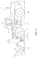
- FIG. 1 is a side view of a wheel loader 1 according to the present embodiment.
- the wheel loader 1 is provided with a vehicle body 2, a work implement 5, front wheels 6F, rear wheels 6R, an operating cabin 7, a boom cylinder 9, and a bucket cylinder 10.
- the boom cylinder 9 is an example of a first actuator and the bucket cylinder 10 is an example of a second actuator.
- the work implement, the front wheels 6F, the rear wheels 6R, and the operating cabin 7 are attached to the vehicle body 2.
- An operator's seat DS on which the operator sits, and an operating lever CL for operating the work implement 5 are disposed inside the operating cabin 7.
- the operating lever CL is an example of an operating device.
- the work implement 5 is attached at the front of the vehicle body 2.
- the work implement 5 has a boom 3 and a bucket 4.
- the boom 3 is attached to the vehicle body 2 and extends from the vehicle body 2 in the forward direction.
- the boom 3 is supported by the vehicle body 2 in a manner that allows rotating up and down (elevating).
- a boom angle detection sensor 3a is disposed at a base end part of the boom 3.
- the boom angle detection sensor 3a detects the angle of the boom 3 with respect to the horizontal direction.
- an automatic lowering control is executed for automatically rotating and lowering the boom 3.
- the automatic lowering control is described below.
- the bucket 4 has an opening part 4H and a claw 4C.
- the bucket 4 scoops a load of sand or gravel and the like with the claw 4C.
- the load scooped with the claw 4C enters into the bucket 4 from the opening part 4H.
- the bucket 4 is attached to the tip end part of the boom 3.
- the bucket 4 is supported by the boom 3 in a manner that allows rotating forward and backward. In the present description, rotating the bucket 4 to the rear is called “tilting" and rotating the bucket 4 forward is called “dumping.”
- the front wheels 6F and the rear wheels 6R are in contact with a road surface R.
- the wheel loader 1 travels due to the front wheels 6F and the rear wheels 6R rotating on the road surface R.
- the wheel loader 1 is steered by bending the vehicle body 2 between the front wheels 6F and the rear wheels 6R.
- the boom cylinder 9 is coupled to the vehicle body 2 and the boom 3.
- the boom 3 rotates up and down due to the extension and contraction of the boom cylinder 9.
- the bucket cylinder 10 is coupled to the vehicle body 2 and an upper end part of a bell crank 11.
- the bell crank 11 is rotatably supported at the tip end part of a supporting member 12 that is fixed to the boom 3.
- a lower end part of the bell crank 11 is coupled to the bucket 4 via a coupling member 13.
- the bucket 4 tilts and dumps forward and backward around a portion supported by the boom 3 due to the extension and contraction of the bucket cylinder 10.
- a bucket angle detection sensor 4a is disposed at a tip end part of the supporting member 12. The bucket angle detection sensor 4a detects the angle of the bottom surface of the bucket 4 with respect to the horizontal direction.
- the operating lever CL is used for raising and lowering the boom 3 due to the extension and contraction of the boom cylinder 9.
- the boom 3 is lowered when the operating lever CL is operated to the lowering side (forward in the present embodiment) relative to a neutral region.
- the boom 3 is raised when the operating lever CL is operated to the raising side (backward in the present embodiment) relative to the neutral position.
- the boom 3 is stopped when the operating lever CL is positioned in the neutral region between the raising side and the lowering side.
- the operating lever CL is used for tilting or dumping the bucket 4 due to the extension and contraction of the bucket cylinder 10.
- the bucket 4 is tilted when the operating lever CL is operated to the tilt side (leftward in the present embodiment) relative to the neutral region.
- the bucket 4 is dumped when the operating lever CL is operated to the dump side (rightward in the present embodiment) relative to the neutral region.
- the bucket 4 is stopped when the operating lever CL is positioned in the neutral region between the tilt side and the dump side.
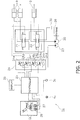
- FIG. 2 is a block diagram illustrating a control system 1a for controlling the operations of the wheel loader 1.
- the control system 1a of the wheel loader 1 is provided with a work implement pump 20, a boom operation valve 21, a bucket operation valve 22, a pilot pump 23, a work implement electronic control valve 24, and a controller 25.
- the work implement pump 20 is driven by an engine 26 as a drive force generation source mounted in the wheel loader 1.
- the work implement pump 20 discharges hydraulic fluid to the boom operation valve 21 and the bucket operation valve 22.
- the boom operation valve 21 and the bucket operation valve 22 are both hydraulic pilot-type operation valves.
- the boom operation valve 21 is connected to the boom cylinder 9 and the bucket operation valve 22 is connected to the bucket cylinder 10.
- the boom operation valve 21 is a switching valve for switching the respective flow paths of a head side port of the boom cylinder 9 and a bottom side port of the boom cylinder 9.
- the boom operation valve 21 has a floating position for enabling the head side and the bottom side of the boom cylinder 9 to communicate.
- both the head side and the bottom side of the boom cylinder 9 are connected to a hydraulic fluid tank 30.
- the bucket operation valve 22 is a switching valve for switching the respective flow paths of a head side port of the bucket cylinder 10 and a bottom side port of the bucket cylinder 10.
- the respective pilot pressure receiving parts of the boom operation valve 21 and the bucket operation valve 22 are connected to the work implement electronic control valve 24 via the pilot pump 23.
- the pilot pump 23 is driven by the engine 26.
- the pilot pump 23 supplies hydraulic fluid at a pilot pressure to the respective pilot pressure receiving parts of the boom operation valve 21 and the bucket operation valve 22 via the work implement electronic control valve 24.
- the work implement electronic control valve 24 has a boom lowering control valve 24a, a boom raising control valve 24b, a bucket dump control valve 24c, and a bucket tilt control valve 24d.
- the boom lowering control valve 24a and the boom raising control valve 24b are connected respectively to a pair of pilot pressure receiving parts of the boom operation valve 21.
- the bucket dump control valve 24c and the bucket tilt control valve 24d are connected respectively to a pair of pilot pressure receiving parts of the bucket operation valve 22.
- Command signals from the controller 25 are inputted respectively to a solenoid command part 24e of the boom lowering control valve 24a, a solenoid command part 24f of the boom raising control valve 24b, a solenoid command part 24g of the bucket dump control valve 24c, and a solenoid command part 24h of the bucket tilt control valve 24d.
- the boom operation valve 21, the boom lowering control valve 24a, the boom raising control valve 24b, and the boom cylinder 9 function as a boom driving part for raising and lowering the boom 3.
- the bucket operation valve 22, the bucket dump control valve 24c, the bucket tilt control valve 24d, and the bucket cylinder 10 function as a bucket driving part for tilting and dumping the bucket 4.
- the controller 25 is, for example, a computer.
- the controller 25 includes a processing part such as a central processing unit (CPU) or the like, and a storage unit such as a read only memory (ROM) or the like.
- the controller 25 controls the operation of the work implement 5 by consecutively executing various commands stored in a computer program.
- the controller 25 is connected to a boom lever potentiometer 27, a bucket lever potentiometer 28, a display 29, the boom angle detection sensor 3a, and the bucket angle detection sensor 4a.
- the boom lever potentiometer 27 is provided on the operating lever CL.
- the boom lever potentiometer 27 detects the operation amount of the operating lever CL in the front-back direction.
- the bucket lever potentiometer 28 is provided on the operating lever CL.
- the bucket lever potentiometer 28 detects the operation amount of the operating lever CL in the left-right direction.
- the controller 25 switches the boom operation valve 21 thereby enabling the head side of the boom cylinder 9 to communicate with the hydraulic fluid tank 30 and enabling the bottom side of the boom cylinder 9 to communicate with the work implement pump 20. Consequently, the boom 3 is raised.
- the controller 25 switches the boom operation valve 21 thereby enabling the bottom side of the boom cylinder 9 to communicate with the hydraulic fluid tank 30 and enabling the head side of the boom cylinder 9 to communicate with the work implement pump 20. Consequently, the boom 3 is lowered by rotating.
- the controller 25 drives the boom 3 at a driving speed corresponding to the operation amount of the operating lever CL.
- the controller 25 switches the bucket operation valve 22 thereby enabling the head side of the bucket cylinder 10 to communicate with the hydraulic fluid tank 30 and enabling the bottom side of the bucket cylinder 10 to communicate with the work implement pump 20. Consequently, the bucket 4 is tilted forward.
- the controller 25 switches the bucket operation valve 22 thereby enabling the bottom side of the bucket cylinder 10 to communicate with the hydraulic fluid tank 30 and enabling the head side of the bucket cylinder 10 to communicate with the work implement pump 20. Consequently, the bucket 4 dumps to the rear.
- the controller 25 drives the bucket 4 at a driving speed corresponding to the operation amount of the operating lever CL.
- the controller 25 starts the execution of the automatic lowering control for automatically rotating and lowering the boom 3 when the operating lever CL is operated by a predetermined operation amount or greater to the lowering side.
- the lowering speed of the boom 3 during the automatic lowering control can be inputted by the operator on a setting screen displayed on the display 29.
- a touch panel-type monitor can be used on the display 29.
- the controller 25 sets the speed inserted on the display 29 as the lowering speed during the automatic lowering control.
- the controller 25 controls a boom driving part so that the lowering speed to which the boom 3 is set is maintained during the execution of the automatic lowering control.
- the controller 25 sets the boom cylinder 9 to a floating state when it is detected that the bucket 4 has reached a grounding position during the execution of the automatic lowering control.
- the floating state is a state in which the head side and the bottom side of the boom cylinder 9 and the tanks are in communication with each other.
- the controller 25 sets the boom cylinder 9 to the floating state by switching the boom operation valve 21 to a floating position.
- the bucket 4 is not held by the boom cylinder 9 because the boom cylinder 9 in the floating state is expandable. As a result, the bucket 4 enters a state of being placed on the ground surface under its own weight. When the wheel loader 1 moves in reverse under the above state, leveling work of the ground surface can be performed effectively with the bucket 4.
- the controller 25 detects that the bucket 4 has come into contact with the ground on the basis of the angles of the respective boom angle detection sensor 3a and the bucket angle detection sensor 4a. Specifically, the attitude of the boom cylinder 9 is sensed on the basis of an output value of the boom angle detection sensor 3a, and the attitude of the bucket 4 is sensed on the basis of an output value of the bucket angle detection sensor 4a, whereby it can be determined whether or not any portion of the bucket 4 has reached the grounding position.
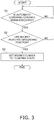
- the automatic lowering control performed by the controller 25 will be explained with reference to the flow chart illustrated in FIG. 3 .
- step S1 the controller 25 determines whether the automatic lowering control is being executed.
- the processing advances to step S2 when the automatic lowering control is being executed, and the processing repeats step S1 when the automatic lowering control is not being executed.
- step S2 the controller 25 determines whether or not the bucket 4 has reached the grounding position on the basis of the respective angles of the boom angle detection sensor 3a and the bucket angle detection sensor 4a.
- the processing advances to step S3 when the bucket 4 has reached the grounding position, and the processing returns to step S1 when the bucket has not reached the grounding position.
- step S3 the controller 25 sets the boom cylinder 9 to the floating state by switching the boom operation valve 21 to the floating position. As a result, the bucket 4 enters a state of being placed on the ground surface under its own weight. Thereafter, the controller 25 ends the automatic lowering control.
- the controller 25 detects that the bucket 4 is in contact with the ground on the basis of the respective angles of the boom angle detection sensor 3a and the bucket angle detection sensor 4a in the above embodiment, the fact that the bucket 4 has come into contact with the ground can be detected with various methods.
- the controller 25 can detect that the bucket 4 is in contact with the ground on the basis of the angle of the boom angle detection sensor 3a only.
- the controller 25 can detect that the bucket 4 is in contact with the ground on the basis of the stroke amount of the boom cylinder 9.
- the wheel loader 1 may be provided with a boom stroke sensor for the boom cylinder 9.
- the controller 25 can detect that the bucket 4 is in contact with the ground on the basis of the stroke amount of the boom cylinder 9 and the stroke amount of the bucket cylinder 10.
- the wheel loader 1 may be provided with a boom stroke sensor for the boom cylinder 9 for detecting the stroke amount of the boom cylinder 9, and a bucket stroke sensor for detecting the stroke amount of the bucket cylinder 10.
- the controller 25 can detect that the bucket 4 is in contact with the ground on the basis of the fact that hydraulic pressure at the bottom side of the boom cylinder 9 is equal to or less than a predetermined threshold.
- the wheel loader 1 may be provided with a hydraulic pressure sensor for sensing the hydraulic pressure at the bottom side of the boom cylinder 9.
- the execution starting condition of the automatic lowering control is not limited in this way.
- the controller 25 may execute the automatic lowering control when the operating lever CL is returned to a neutral position after the operating lever CL has been moved by the predetermined operation amount or greater toward the lowering side.
- the controller 25 may execute the automatic lowering control when the operator presses an execution button for the automatic lowering control after the operating lever CL has been operated by the predetermined operation amount or more to the lowering side.
- controller 25 sets the speed inputted on the setting screen displayed on the display 29 as the predetermined speed for the automatic lowering control
- the present invention is not limited in this way.
- the controller 25 may set the predetermined speed in response to the position of a dial for setting the predetermined speed for the automatic lowering control.
- the controller 25 sets the boom cylinder 9 to the floating state when it is detected that the bucket 4 has reached the grounding position
- the controller 25 may set the boom cylinder 9 to the floating state when it is detected that the bucket 4 has reached a predetermined position.
- the predetermined position is preferably set to a position where the bucket 4 is near the ground surface. In this case, the bucket 4 can be brought into contact with the ground easily and the shock when the bucket 4 comes into contact with the ground can be limited.
Landscapes
- Engineering & Computer Science (AREA)
- Mining & Mineral Resources (AREA)
- Civil Engineering (AREA)
- General Engineering & Computer Science (AREA)
- Structural Engineering (AREA)
- Mechanical Engineering (AREA)
- Physics & Mathematics (AREA)
- Fluid Mechanics (AREA)
- Operation Control Of Excavators (AREA)
- Lifting Devices For Agricultural Implements (AREA)
Applications Claiming Priority (2)
| Application Number | Priority Date | Filing Date | Title |
|---|---|---|---|
| JP2017205489A JP7164294B2 (ja) | 2017-10-24 | 2017-10-24 | 作業車両 |
| PCT/JP2018/036430 WO2019082600A1 (fr) | 2017-10-24 | 2018-09-28 | Véhicule de travail |
Publications (3)
| Publication Number | Publication Date |
|---|---|
| EP3584374A1 true EP3584374A1 (fr) | 2019-12-25 |
| EP3584374A4 EP3584374A4 (fr) | 2021-01-13 |
| EP3584374B1 EP3584374B1 (fr) | 2026-02-25 |
Family
ID=66247800
Family Applications (1)
| Application Number | Title | Priority Date | Filing Date |
|---|---|---|---|
| EP18870208.8A Active EP3584374B1 (fr) | 2017-10-24 | 2018-09-28 | Véhicule de travail |
Country Status (5)
| Country | Link |
|---|---|
| US (1) | US11879234B2 (fr) |
| EP (1) | EP3584374B1 (fr) |
| JP (1) | JP7164294B2 (fr) |
| CN (1) | CN110462137B (fr) |
| WO (1) | WO2019082600A1 (fr) |
Cited By (2)
| Publication number | Priority date | Publication date | Assignee | Title |
|---|---|---|---|---|
| WO2022016146A1 (fr) * | 2020-07-17 | 2022-01-20 | Cnh Industrial America Llc | Système et procédé servant à maintenir une position de bras de chargeur en cours de fonctionnement d'un véhicule de chantier à l'aide d'un mode de commande de conduite |
| IT202000021808A1 (it) * | 2020-09-16 | 2022-03-16 | Cnh Ind Italia Spa | Procedimento di controllo per eseguire una funzione flottante di un braccio, sistemi di controllo corrispondenti e macchine operatrici comprendenti tali sistemi di controllo |
Families Citing this family (4)
| Publication number | Priority date | Publication date | Assignee | Title |
|---|---|---|---|---|
| JP6964109B2 (ja) * | 2019-03-26 | 2021-11-10 | 日立建機株式会社 | 作業機械 |
| CN112922074A (zh) * | 2021-01-28 | 2021-06-08 | 三一重机有限公司 | 动臂浮动的自适应启动方法及装置 |
| CN117500986A (zh) | 2021-06-28 | 2024-02-02 | 斗山山猫北美公司 | 用于控制挖掘机和其他动力机器的系统和方法 |
| CN115606351B (zh) * | 2022-10-08 | 2025-10-10 | 江苏徐工工程机械研究院有限公司 | 一种拖拉机机具控制方法、系统及拖拉机 |
Family Cites Families (35)
| Publication number | Priority date | Publication date | Assignee | Title |
|---|---|---|---|---|
| US3487958A (en) * | 1968-01-31 | 1970-01-06 | Caterpillar Tractor Co | Self-cycling loader |
| US3726428A (en) * | 1971-02-04 | 1973-04-10 | Int Harvester Co | Control circuit for front end loader |
| US4286417A (en) * | 1979-08-08 | 1981-09-01 | Robert T. Nelson | Blasting machine with position sensing and adjustment |
| JP2546294B2 (ja) | 1987-10-09 | 1996-10-23 | 井関農機株式会社 | ローダの操作装置 |
| JPH089234Y2 (ja) * | 1989-06-06 | 1996-03-13 | ヤンマー農機株式会社 | 持上げ運搬作業機 |
| JPH0794737B2 (ja) * | 1989-08-02 | 1995-10-11 | 株式会社小松製作所 | 油圧掘削機における直線掘削制御装置 |
| JPH06185093A (ja) * | 1992-12-18 | 1994-07-05 | Hitachi Constr Mach Co Ltd | ホイールローダのフロント制御装置 |
| JP3379799B2 (ja) | 1993-09-30 | 2003-02-24 | 株式会社小松製作所 | 産業車両のバケットレベラ装置 |
| JP2749253B2 (ja) * | 1993-10-04 | 1998-05-13 | 新キャタピラー三菱株式会社 | ショベルのバケット刃先位置検出方法 |
| JP3024910B2 (ja) * | 1994-07-18 | 2000-03-27 | 新キャタピラー三菱株式会社 | 掘削用建設機械における自動掘削制御装置 |
| US5642653A (en) | 1995-10-23 | 1997-07-01 | Caterpillar Inc. | Method and apparatus for providing detents on an electronic control handle |
| US5924516A (en) * | 1996-01-16 | 1999-07-20 | Clark Equipment Company | Electronic controls on a skid steer loader |
| JP3154656B2 (ja) | 1996-03-21 | 2001-04-09 | 日立建機株式会社 | 建設機械の制御ユニットにおける制御定数の設定方法、建設機械の制御方法及び建設機械の制御ユニット |
| JP4383611B2 (ja) * | 1999-12-09 | 2009-12-16 | ヤンマー株式会社 | フロントローダ |
| US7076354B2 (en) * | 2000-03-24 | 2006-07-11 | Komatsu Ltd. | Working unit control apparatus of excavating and loading machine |
| US6640468B2 (en) * | 2001-02-27 | 2003-11-04 | M. P. Menze Research & Development Inc. | Vehicle mounted snowplow impact monitoring system and method |
| US6871710B1 (en) * | 2001-05-01 | 2005-03-29 | Altec Industries, Inc. | Rotational float for rotating equipment |
| SE519970C2 (sv) * | 2001-09-07 | 2003-05-06 | Bruun Ecomate Ab | Hydrauldrivet armsystem med flytreglering |
| SE526720C2 (sv) * | 2003-05-28 | 2005-10-25 | Volvo Constr Equip Holding Se | System och förfarande för förflyttning av ett redskap hos ett fordon |
| DE102004012382B4 (de) * | 2004-03-13 | 2014-03-13 | Deere & Company | Hydraulische Anordnung |
| DE102004012362A1 (de) * | 2004-03-13 | 2005-09-22 | Deere & Company, Moline | Hydraulische Anordnung |
| US7869922B2 (en) * | 2004-04-12 | 2011-01-11 | Cnh America Llc | Method and apparatus to put a windrower header in the transport mode under specified conditions |
| JP4436241B2 (ja) | 2004-12-10 | 2010-03-24 | 株式会社小松製作所 | 建設車両 |
| JP4855124B2 (ja) * | 2006-04-06 | 2012-01-18 | 株式会社小松製作所 | ブルドーザ、作業機械及びブレードの自由落下方法 |
| US8500387B2 (en) * | 2007-06-15 | 2013-08-06 | Deere & Company | Electronic parallel lift and return to carry or float on a backhoe loader |
| US8602153B2 (en) * | 2007-08-06 | 2013-12-10 | Extendquip Llc | Extendable frame work vehicle |
| US8103418B2 (en) * | 2007-08-06 | 2012-01-24 | Extendquip Llc | Extendable frame work vehicle having lift member movable in a true vertical fashion |
| US20090099737A1 (en) * | 2007-10-12 | 2009-04-16 | Wendte Keith W | Method and apparatus for optimization of agricultural field operations using weather, product and environmental information |
| JP5390208B2 (ja) | 2009-01-30 | 2014-01-15 | 株式会社クボタ | フロントローダ |
| JP5277449B2 (ja) | 2009-03-26 | 2013-08-28 | 株式会社小松製作所 | 作業車両並びに作業車両の制御方法および制御装置 |
| DE112013006501T5 (de) * | 2013-01-24 | 2016-03-31 | Volvo Construction Equipment Ab | Vorrichtung und Verfahren zum Steuern einer Flussrate bei Baumaschinen |
| EP2853641B1 (fr) | 2013-07-12 | 2017-06-14 | Komatsu Ltd. | Véhicule de travail et procédé de commande de véhicule de travail |
| CN106068353B (zh) * | 2014-03-03 | 2018-06-26 | 凯斯纽荷兰(中国)管理有限公司 | 具有返回挖掘功能的工作机 |
| US10280948B2 (en) | 2014-04-04 | 2019-05-07 | Volvo Construction Equipment Ab | Hydraulic system and method for controlling an implement of a working machine |
| US10407876B2 (en) * | 2015-06-02 | 2019-09-10 | Doosan Infracore Co., Ltd. | Hydraulic system of construction machinery |
-
2017
- 2017-10-24 JP JP2017205489A patent/JP7164294B2/ja active Active
-
2018
- 2018-09-28 CN CN201880021940.5A patent/CN110462137B/zh active Active
- 2018-09-28 EP EP18870208.8A patent/EP3584374B1/fr active Active
- 2018-09-28 WO PCT/JP2018/036430 patent/WO2019082600A1/fr not_active Ceased
- 2018-09-28 US US16/496,094 patent/US11879234B2/en active Active
Cited By (5)
| Publication number | Priority date | Publication date | Assignee | Title |
|---|---|---|---|---|
| WO2022016146A1 (fr) * | 2020-07-17 | 2022-01-20 | Cnh Industrial America Llc | Système et procédé servant à maintenir une position de bras de chargeur en cours de fonctionnement d'un véhicule de chantier à l'aide d'un mode de commande de conduite |
| US12523000B2 (en) | 2020-07-17 | 2026-01-13 | Cnh Industrial America Llc | System and method for maintaining loader arm position during the operation of a work vehicle using a ride control mode |
| IT202000021808A1 (it) * | 2020-09-16 | 2022-03-16 | Cnh Ind Italia Spa | Procedimento di controllo per eseguire una funzione flottante di un braccio, sistemi di controllo corrispondenti e macchine operatrici comprendenti tali sistemi di controllo |
| WO2022058400A1 (fr) * | 2020-09-16 | 2022-03-24 | Cnh Industrial Italia S.P.A. | Procédé de commande pour exécuter une fonction flottante d'une flèche d'un engin de chantier, système de commande correspondant et engin de chantier comprenant un tel système de commande |
| US12577756B2 (en) | 2020-09-16 | 2026-03-17 | Cnh Industrial Italia S.P.A. | Control method for executing a floating function of a boom, corresponding control systems and work vehicles comprising such control systems |
Also Published As
| Publication number | Publication date |
|---|---|
| WO2019082600A1 (fr) | 2019-05-02 |
| CN110462137B (zh) | 2022-02-25 |
| JP7164294B2 (ja) | 2022-11-01 |
| EP3584374A4 (fr) | 2021-01-13 |
| US20200056354A1 (en) | 2020-02-20 |
| EP3584374B1 (fr) | 2026-02-25 |
| JP2019078066A (ja) | 2019-05-23 |
| CN110462137A (zh) | 2019-11-15 |
| US11879234B2 (en) | 2024-01-23 |
Similar Documents
| Publication | Publication Date | Title |
|---|---|---|
| US11879234B2 (en) | Work vehicle | |
| KR102556315B1 (ko) | 쇼벨 | |
| US20160040391A1 (en) | Work vehicle and method of controlling work vehicle | |
| US7637039B2 (en) | Method and apparatus for controlling hydraulic pump for working machine of working vehicle | |
| KR102649042B1 (ko) | 작업 차량 | |
| US9702117B2 (en) | Work vehicle control method, work vehicle control device, and work vehicle | |
| KR20110069942A (ko) | 건설기계의 작업기 위치제어장치 및 작업기 위치제어방법 | |
| US9809948B2 (en) | Work vehicle control method, work vehicle control device, and work vehicle | |
| JP7450526B2 (ja) | 作業車両 | |
| JP2021011819A (ja) | 作業車両及び作業車両の制御方法 | |
| JP7024139B2 (ja) | 作業機械 | |
| EP3584376B1 (fr) | Engin de chantier et son procédé de commande | |
| US12509860B2 (en) | Control system for loading machine, control method therefor, and loading machine | |
| EP3572589B1 (fr) | Véhicule de travail et procédé de commande de véhicule de travail | |
| JP2026050042A (ja) | 建設機械のための建設機械制御装置及び建設機械 |
Legal Events
| Date | Code | Title | Description |
|---|---|---|---|
| STAA | Information on the status of an ep patent application or granted ep patent |
Free format text: STATUS: THE INTERNATIONAL PUBLICATION HAS BEEN MADE |
|
| PUAI | Public reference made under article 153(3) epc to a published international application that has entered the european phase |
Free format text: ORIGINAL CODE: 0009012 |
|
| STAA | Information on the status of an ep patent application or granted ep patent |
Free format text: STATUS: REQUEST FOR EXAMINATION WAS MADE |
|
| 17P | Request for examination filed |
Effective date: 20190918 |
|
| AK | Designated contracting states |
Kind code of ref document: A1 Designated state(s): AL AT BE BG CH CY CZ DE DK EE ES FI FR GB GR HR HU IE IS IT LI LT LU LV MC MK MT NL NO PL PT RO RS SE SI SK SM TR |
|
| AX | Request for extension of the european patent |
Extension state: BA ME |
|
| A4 | Supplementary search report drawn up and despatched |
Effective date: 20201211 |
|
| RIC1 | Information provided on ipc code assigned before grant |
Ipc: A01B 63/10 20060101ALI20201207BHEP Ipc: E02F 3/43 20060101AFI20201207BHEP |
|
| DAV | Request for validation of the european patent (deleted) | ||
| DAX | Request for extension of the european patent (deleted) | ||
| STAA | Information on the status of an ep patent application or granted ep patent |
Free format text: STATUS: EXAMINATION IS IN PROGRESS |
|
| 17Q | First examination report despatched |
Effective date: 20230313 |
|
| GRAP | Despatch of communication of intention to grant a patent |
Free format text: ORIGINAL CODE: EPIDOSNIGR1 |
|
| STAA | Information on the status of an ep patent application or granted ep patent |
Free format text: STATUS: GRANT OF PATENT IS INTENDED |
|
| INTG | Intention to grant announced |
Effective date: 20251117 |
|
| GRAS | Grant fee paid |
Free format text: ORIGINAL CODE: EPIDOSNIGR3 |
|
| GRAA | (expected) grant |
Free format text: ORIGINAL CODE: 0009210 |
|
| STAA | Information on the status of an ep patent application or granted ep patent |
Free format text: STATUS: THE PATENT HAS BEEN GRANTED |
|
| AK | Designated contracting states |
Kind code of ref document: B1 Designated state(s): AL AT BE BG CH CY CZ DE DK EE ES FI FR GB GR HR HU IE IS IT LI LT LU LV MC MK MT NL NO PL PT RO RS SE SI SK SM TR |
|
| REG | Reference to a national code |
Ref country code: CH Ref legal event code: F10 Free format text: ST27 STATUS EVENT CODE: U-0-0-F10-F00 (AS PROVIDED BY THE NATIONAL OFFICE) Effective date: 20260225 Ref country code: GB Ref legal event code: FG4D |
|
| REG | Reference to a national code |
Ref country code: DE Ref legal event code: R096 Ref document number: 602018089454 Country of ref document: DE |
|
| REG | Reference to a national code |
Ref country code: IE Ref legal event code: FG4D |