EP3584407B1 - Kühlrippen für erweiterte grenzschichtmischung - Google Patents
Kühlrippen für erweiterte grenzschichtmischung Download PDFInfo
- Publication number
- EP3584407B1 EP3584407B1 EP19179785.1A EP19179785A EP3584407B1 EP 3584407 B1 EP3584407 B1 EP 3584407B1 EP 19179785 A EP19179785 A EP 19179785A EP 3584407 B1 EP3584407 B1 EP 3584407B1
- Authority
- EP
- European Patent Office
- Prior art keywords
- wall
- airfoil
- trip
- trip strips
- cooling
- Prior art date
- Legal status (The legal status is an assumption and is not a legal conclusion. Google has not performed a legal analysis and makes no representation as to the accuracy of the status listed.)
- Active
Links
Images






Classifications
-
- F—MECHANICAL ENGINEERING; LIGHTING; HEATING; WEAPONS; BLASTING
- F01—MACHINES OR ENGINES IN GENERAL; ENGINE PLANTS IN GENERAL; STEAM ENGINES
- F01D—NON-POSITIVE DISPLACEMENT MACHINES OR ENGINES, e.g. STEAM TURBINES
- F01D5/00—Blades; Blade-carrying members; Heating, heat-insulating, cooling or antivibration means on the blades or the members
- F01D5/12—Blades
- F01D5/14—Form or construction
- F01D5/18—Hollow blades, i.e. blades with cooling or heating channels or cavities; Heating, heat-insulating or cooling means on blades
- F01D5/187—Convection cooling
- F01D5/188—Convection cooling with an insert in the blade cavity to guide the cooling fluid, e.g. forming a separation wall
-
- F—MECHANICAL ENGINEERING; LIGHTING; HEATING; WEAPONS; BLASTING
- F01—MACHINES OR ENGINES IN GENERAL; ENGINE PLANTS IN GENERAL; STEAM ENGINES
- F01D—NON-POSITIVE DISPLACEMENT MACHINES OR ENGINES, e.g. STEAM TURBINES
- F01D5/00—Blades; Blade-carrying members; Heating, heat-insulating, cooling or antivibration means on the blades or the members
- F01D5/12—Blades
- F01D5/14—Form or construction
- F01D5/18—Hollow blades, i.e. blades with cooling or heating channels or cavities; Heating, heat-insulating or cooling means on blades
- F01D5/187—Convection cooling
-
- F—MECHANICAL ENGINEERING; LIGHTING; HEATING; WEAPONS; BLASTING
- F01—MACHINES OR ENGINES IN GENERAL; ENGINE PLANTS IN GENERAL; STEAM ENGINES
- F01D—NON-POSITIVE DISPLACEMENT MACHINES OR ENGINES, e.g. STEAM TURBINES
- F01D25/00—Component parts, details, or accessories, not provided for in, or of interest apart from, other groups
- F01D25/08—Cooling; Heating; Heat-insulation
- F01D25/12—Cooling
-
- F—MECHANICAL ENGINEERING; LIGHTING; HEATING; WEAPONS; BLASTING
- F01—MACHINES OR ENGINES IN GENERAL; ENGINE PLANTS IN GENERAL; STEAM ENGINES
- F01D—NON-POSITIVE DISPLACEMENT MACHINES OR ENGINES, e.g. STEAM TURBINES
- F01D5/00—Blades; Blade-carrying members; Heating, heat-insulating, cooling or antivibration means on the blades or the members
- F01D5/12—Blades
- F01D5/14—Form or construction
- F01D5/141—Shape, i.e. outer, aerodynamic form
-
- F—MECHANICAL ENGINEERING; LIGHTING; HEATING; WEAPONS; BLASTING
- F05—INDEXING SCHEMES RELATING TO ENGINES OR PUMPS IN VARIOUS SUBCLASSES OF CLASSES F01-F04
- F05D—INDEXING SCHEME FOR ASPECTS RELATING TO NON-POSITIVE-DISPLACEMENT MACHINES OR ENGINES, GAS-TURBINES OR JET-PROPULSION PLANTS
- F05D2240/00—Components
- F05D2240/10—Stators
- F05D2240/12—Fluid guiding means, e.g. vanes
- F05D2240/127—Vortex generators, turbulators, or the like, for mixing
-
- F—MECHANICAL ENGINEERING; LIGHTING; HEATING; WEAPONS; BLASTING
- F05—INDEXING SCHEMES RELATING TO ENGINES OR PUMPS IN VARIOUS SUBCLASSES OF CLASSES F01-F04
- F05D—INDEXING SCHEME FOR ASPECTS RELATING TO NON-POSITIVE-DISPLACEMENT MACHINES OR ENGINES, GAS-TURBINES OR JET-PROPULSION PLANTS
- F05D2250/00—Geometry
- F05D2250/10—Two-dimensional
- F05D2250/18—Two-dimensional patterned
- F05D2250/183—Two-dimensional patterned zigzag
-
- F—MECHANICAL ENGINEERING; LIGHTING; HEATING; WEAPONS; BLASTING
- F05—INDEXING SCHEMES RELATING TO ENGINES OR PUMPS IN VARIOUS SUBCLASSES OF CLASSES F01-F04
- F05D—INDEXING SCHEME FOR ASPECTS RELATING TO NON-POSITIVE-DISPLACEMENT MACHINES OR ENGINES, GAS-TURBINES OR JET-PROPULSION PLANTS
- F05D2250/00—Geometry
- F05D2250/70—Shape
- F05D2250/75—Shape given by its similarity to a letter, e.g. T-shaped
-
- F—MECHANICAL ENGINEERING; LIGHTING; HEATING; WEAPONS; BLASTING
- F05—INDEXING SCHEMES RELATING TO ENGINES OR PUMPS IN VARIOUS SUBCLASSES OF CLASSES F01-F04
- F05D—INDEXING SCHEME FOR ASPECTS RELATING TO NON-POSITIVE-DISPLACEMENT MACHINES OR ENGINES, GAS-TURBINES OR JET-PROPULSION PLANTS
- F05D2260/00—Function
- F05D2260/20—Heat transfer, e.g. cooling
- F05D2260/221—Improvement of heat transfer
- F05D2260/2212—Improvement of heat transfer by creating turbulence
-
- Y—GENERAL TAGGING OF NEW TECHNOLOGICAL DEVELOPMENTS; GENERAL TAGGING OF CROSS-SECTIONAL TECHNOLOGIES SPANNING OVER SEVERAL SECTIONS OF THE IPC; TECHNICAL SUBJECTS COVERED BY FORMER USPC CROSS-REFERENCE ART COLLECTIONS [XRACs] AND DIGESTS
- Y02—TECHNOLOGIES OR APPLICATIONS FOR MITIGATION OR ADAPTATION AGAINST CLIMATE CHANGE
- Y02T—CLIMATE CHANGE MITIGATION TECHNOLOGIES RELATED TO TRANSPORTATION
- Y02T50/00—Aeronautics or air transport
- Y02T50/60—Efficient propulsion technologies, e.g. for aircraft
Definitions
- the present invention generally relates to cooling of gas turbine engines, and more particularly to the cooling of an airfoil for a gas turbine engine.
- Gas turbine engines such as those which power aircraft and industrial equipment, may employ a compressor to compress air that is drawn into the engine and a turbine to capture energy associated with a combustion of a fuel-air mixture.
- Turbine airfoils are subjected to elevated temperatures as a result of such combustion.
- most engines incorporate a cooling technique that utilizes a flow of cooling air within cavities/channels of the airfoil.
- the cooling air absorbs heat from the walls of the airfoil, thereby reducing the operating temperature of the airfoil walls.
- the cooling air represents a resource of the engine and its use impacts the performance/efficiency of the engine. Accordingly, the cooling air must be used effectively in order to promote engine efficiency.
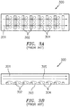
- FIGS. 3A-3B illustrate a(n arrangement of a) channel 300.
- cooling air 301 flows through the channel 300 in, e.g., a left-to-right fashion.
- Trip strips 302 (which are located on a wall 303 of the channel 300) trip/impede the flow of the cooling air 301 through the channel 300 and increase the turbulence of the cooling air in the channel 300, thereby generating separated regions of flow 304 behind the trip strips 302.
- the tripped/separated flows 304 have a lower velocity from a bulk flow 305 (where the bulk flow 305 corresponds to the portion of the cooling air 301 that bypasses/is not impeded by the trip strips 302), tend to swirl and mix, and thus increase an exchange of heat between the channel walls (e.g., the wall 303) and the cooling air 301.
- WO2014175937A2 , WO2004035992A1 and DE19526917A1 disclose airfoils with corrugated patterns.
- trip strips While the use of trip strips is generally effective in terms of reducing the temperature of a channel wall, further enhancements are necessary to increase the effectiveness of the cooling air (e.g., to increase the heat transfer coefficient).
- an airfoil for a gas turbine engine as set out in claim 1 is provided.
- the airfoil comprises a plurality of trip strips coupled to the first wall, where the plurality of trip strips include the trip strip.
- at least part of each of the plurality of trips strips forms a corrugated pattern.
- the first leg and the second leg define an angle between them, and the angle is less than ninety degrees and greater than zero degrees.
- the airfoil comprises a second trip strip coupled to the second wall, where the first wall and the second wall are opposed to one another.
- the airfoil comprises a third wall and a fourth wall that at least partially define the channel, a third trip strip coupled to the third wall, and a fourth trip strip coupled to the fourth wall.
- the trip strip includes a first member that forms a part of the corrugated pattern and a second member that forms a part of the corrugated pattern, and where the first member includes a first leg that has a first length and the second member includes a second leg that has a second length, and where the first length is different from the second length.
- the corrugated pattern is defined by a plurality of members that each include a vertex, and each of the vertices of the corrugated pattern is skewed relative to a flow direction of a fluid in the channel. In some embodiments, the vertices are skewed by an angle within a range of thirty degrees and sixty degrees relative to the flow direction.
- a gas turbine engine according to claim 9 is provided.
- the airfoil is part of a non-rotatable vane.
- the airfoil is part of a rotatable blade.
- the channel conveys a fluid to cool the first wall and the second wall.
- the gas turbine engine comprises a pipe coupled to the compressor section and the turbine section that conveys the fluid from the compressor section to the turbine section.
- the airfoil includes a second trip strip coupled to the first wall, and the fluid converges and diverges in traversing the channel between the first trip strip and the second trip strip.
- connections are set forth between elements in the following description and in the drawings (the contents of which are included in this disclosure by way of reference). It is noted that these connections are general and, unless specified otherwise, may be direct or indirect and that this specification is not intended to be limiting in this respect.
- a coupling between two or more entities may refer to a direct connection or an indirect connection.
- An indirect connection may incorporate one or more intervening entities and/or a gap/space between entities.
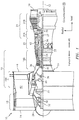
- FIG. 1 is a side cutaway illustration of a geared turbine engine 10.
- This turbine engine 10 extends along an axial centerline 12 between an upstream airflow inlet 14 and a downstream airflow exhaust 16.
- the turbine engine 10 includes a fan section 18, a compressor section 19, a combustor section 20 and a turbine section 21.
- the compressor section 19 includes a low pressure compressor (LPC) section 19A and a high pressure compressor (HPC) section 19B.
- the turbine section 21 includes a high pressure turbine (HPT) section 21A and a low pressure turbine (LPT) section 21B.
- the engine sections 18-21 are arranged sequentially along the centerline 12 within an engine housing 22.
- Each of the engine sections 18-19B, 21A and 21B includes a respective rotor 24-28.
- Each of these rotors 24-28 includes a plurality of rotor blades arranged circumferentially around and connected to one or more respective rotor disks.
- the rotor blades may be formed integral with or mechanically fastened, welded, brazed, adhered and/or otherwise attached to the respective rotor disk(s).
- the fan rotor 24 is connected to a gear train 30, for example, through a fan shaft 32.
- the gear train 30 and the LPC rotor 25 are connected to and driven by the LPT rotor 28 through a low speed shaft 33.
- the HPC rotor 26 is connected to and driven by the HPT rotor 27 through a high speed shaft 34.
- the shafts 32-34 are rotatably supported by a plurality of bearings 36 (e.g., rolling element and/or thrust bearings). Each of these bearings 36 is connected to the engine housing 22 by at least one stationary structure such as, for example, an annular support strut.
- a fan drive gear system which may be incorporated as part of the gear train 30, may be used to separate the rotation of the fan rotor 24 from the rotation of the rotor 25 of the low pressure compressor section 19A and the rotor 28 of the low pressure turbine section 21B.
- FDGS fan drive gear system
- such an FDGS may allow the fan rotor 24 to rotate at a different (e.g., slower) speed relative to the rotors 25 and 28.
- the air within the core gas path 38 may be referred to as "core air”.
- the air within the bypass gas path 40 may be referred to as "bypass air”.
- the core air is directed through the engine sections 19-21, and exits the turbine engine 10 through the airflow exhaust 16 to provide forward engine thrust.
- fuel is injected into a combustion chamber 42 and mixed with compressed core air. This fuel-core air mixture is ignited to power the turbine engine 10.
- the bypass air is directed through the bypass gas path 40 and out of the turbine engine 10 through a bypass nozzle 44 to provide additional forward engine thrust. This additional forward engine thrust may account for a majority (e.g., more than 70 percent) of total engine thrust.
- at least some of the bypass air may be directed out of the turbine engine 10 through a thrust reverser to provide reverse engine thrust.
- FIG. 1 represents one possible configuration for an engine 10. Aspects of the disclosure may be applied in connection with other environments, including additional configurations for gas turbine engines. Aspects of the disclosure may be applied in connection with non-geared engines.
- FIG. 2 a portion of a turbine section 221 of an engine is shown.
- the portion of the turbine section 221 may correspond to a portion of the turbine section 21 of FIG. 1 .
- Also shown in FIG. 2 is an engine longitudinal centerline 212 (which may correspond to the centerline 12 of FIG. 1 ).
- the turbine section 221 may include a case 202 and a conduit/pipe 206.
- the case 202 may be arranged as a full-hoop structure.
- the pipe 206 may supply a cooling fluid (e.g., cooling air) to a vane cavity as is described further below.
- the cooling fluid may be obtained from one or more sources; for example, the cooling fluid may be obtained from a compressor section of an engine (see, e.g., compressor section 19 of FIG. 1 ), from an output of a heat exchanger, etc.
- the turbine section 221 may include alternating stages of rotational structure and static structure.
- the turbine section 221 may include a first rotor disk 214-1 and a second rotor disk 214-2, where the second rotor disk 214-2 is disposed axially aft of the first rotor disk 214-1.
- the rotor disks 214-1 and 214-2 may be coupled to respective airfoils/blades 218-1 and 218-2.
- the airfoils 218-1 and 218-2 may interface to respective seals 222-1 and 222-2.
- the seals 222-1 and 222-2 may be coupled to the case 202.
- Each of the seals 222-1 and 222-2 is frequently referred to as a blade outer air seal (BOAS).
- BOAS blade outer air seal
- Axially disposed between, e.g., the first rotor disk 214-1 and the second rotor disk 214-2 may be a stage of static (e.g., non-rotating) structure, frequently referred to as a vane.
- the vane may include an airfoil 228 that is bounded by a (radially outer) platform 232-1 and a (radially inner) platform 232-2.
- a forward platform rail 208a and an aft platform rail 208b may couple the outer platform 232-1 to the case 202.
- the case 202 and the outer platform 232-1 may at least partially define an outer vane cavity 236-1.
- the inner platform 232-2 and a seal 240 may at least partially define an inner vane cavity 236-2.
- the seal 240 may be arranged as a full-hoop structure.
- the seal 240 may include, or be coupled to, one or more seal lands.
- FIG. 2 illustrates a first seal land 244-1 and a second seal land 244-2.
- the seal lands 244-1 and 244-2 may interface to respective cover plates 248-1 and 248-2.
- the cover plates 248-1 and 248-2 may be coupled to the first rotor disk 214-1 and the second rotor disk 214-2, respectively.
- the cover plates 248-1 and 248-2 may be arranged as full-hoop structures.
- cooling fluid supplied via the pipe 206 may enter the outer vane cavity 236-1.
- the cooling fluid may enter the airfoil 228 (via, e.g., one or more holes/apertures formed in the platform 232-1) and flow in, e.g., a radially inward/inboard direction via one or more cooling channels 258.
- At least a portion of the cooling fluid may be admitted from the cooling channel(s) 258 into the inner vane cavity 236-2 (via, e.g., one or more holes/apertures formed in the platform 232-2).
- the cooling fluid may be provided to a rotor cavity 260 via an orifice 264 defined by the seal 240.
- the rotor cavity 260 may be at least partially defined/bounded by the disks 214-1 and 214-2, the cover plates 248-1 and 248-2, and the seal 240. A portion of the fluid in the rotor cavity 260 may bypass the interfaces between the cover plates 248-1 and 248-2 and their respective seal lands 244-1 and 244-2 and may cool, e.g., the airfoils 218-1 and 218-2.
- the pipe 206 may be coupled to the inner vane cavity 236-2.
- the cooling fluid may initially be supplied to the inner vane cavity 236-2 to cool, e.g., the inner platform 232-2; from the inner vane cavity 236-2, at least a portion of the cooling fluid may traverse the airfoil 228 via the cooling channels 258 and flow to, e.g., the outer vane cavity 236-1.
- the cooling channels 258 may be used to cool or reduce a temperature of the airfoil 228.
- Cooling channel(s) 268-1 and 268-2 may be included in the airfoils 218-1 and 218-2, respectively, to cool or reduce a temperature of the airfoils 218-1 and 218-2.
- Cooling fluid may be routed through the cooling channel(s) 268-1 and 268-2 in a manner similar to that described above in relation to the cooling channels 258. More generally, a component may be manufactured/fabricated to include cooling channels to facilitate a reduction in a temperature of that component.
- cooling channels are described below.
- the cooling channels described below may be implemented in conjunction with one or more of the cooling channels described above (e.g., the cooling channels 258/268-1/268-2).
- FIGS. 4A-4B an example of a cooling channel 400 is shown. Also superimposed in FIGS. 4A-4B is a flow direction, which corresponds to the direction that cooling fluid flows in the channel 400.
- the cooling channel 400 includes trip strips 402 that may be disposed/located on a wall 403 of the cooling channel 400. Whereas each of the trip strips 302 are shown as being substantially straight members in FIG. 3A , each of the trip strips 402 of FIG. 4A may form a corrugated pattern.
- the corrugated pattern may include/be composed of a number of members, where each member may substantially correspond to the shape of the letter 'V' (or, analogously, at least a portion of the shape of one or more of the letters 'E', 'M' or 'W') of the English alphabet as shown in FIG. 4A .
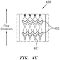
- FIG. 4C A closer view of the trip strips 402 bounded by the box 450 in FIG. 4A is shown in FIG. 4C .
- FIG. 4C Also shown in FIG. 4C is a flow of cooling fluid 401.
- the corrugated pattern of the trip strips 402 may encourage the flow of the cooling fluid 401 over the trip strips 402 to repeatedly converge and diverge as shown in FIG. 4C .
- the cooling fluid flows/paths reach a state of increased (e.g., maximum) convergence, that may establish a local region of high pressure that may have a tendency to want to expand (and hence, diverge the flows/paths) to a lower pressure environment.
- lateral mixing e.g., mixing to the left and right in FIG. 4C
- the lateral mixing may increase the overall mixing that occurs, such that an increase in the heat transfer coefficient may be realized/obtained.
- the cooling fluid 401 may realize less of a pressure drop in traversing the cooling channel 400 since no portion of the corrugated-patterned trip strips 402 are directly opposed to the flow direction. The corrugated-patterned trip strips 402 tend to redirect the flow, rather than stop/oppose the flow.
- a trip strip 402 member may include a first leg/segment 402-1 and a second leg/segment 402-2 that emanate from a vertex 402-3 that collectively form a substantial 'V'-shape as described above.
- the first leg 402-1 and the second leg 402-2 may define an angle 402-4 between them.
- the angle 402-4 may assume one or more values.
- the angle 402-4 may be a value that is less than or equal to ninety degrees and greater than zero degrees.
- An angle equal to zero degrees (or approximately zero degrees) may impose challenges in terms of manufacturability/reliability (e.g., elevated stress concentrations may be present at the interface/vertex 402-3 between the legs 402-1 and 402-2 when the angle 402-4 is approximately equal to zero). Accordingly, trade-offs may be made to arrive at a value of the angle 402-4 that is suitable for the particular application at hand.
- One or more simulations, tests, etc. may be conducted to determine/verify the value of the angle 402-4 to use for the application.
- FIGS. 4A-4D may be utilized in some examples.
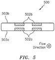
- a cooling channel 500 may include one or more (corrugated-patterned) trip strips 502a disposed on a first wall 503a and one or more (corrugated-patterned) trip strips 502b disposed on a second wall 503b.
- the cooling channel 500 may be used to enhance cooling with respect to two cooling channel walls (relative to the cooling channel 400 with a single wall 403 that includes trip strips 402 as shown in FIG. 4B ).
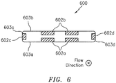
- FIG. 6 illustrates a cooling channel 600 that may include one or more (corrugated-patterned) trip strips 602a, 602b, 602c, and 602d disposed on walls 603a, 603b, 603c, and 603d, respectively.
- the cooling channel 600 may be used in applications/environments characterized by elevated/extreme temperatures, where the use of cooling is of paramount importance.
- cooling efficiency in terms of an amount of cooling obtained per dimension of trip strip used, the cooling efficiency that is obtained in cooling channels 400 and 500 may be greater than the cooling efficiency that is obtained in the cooling channel 600.
- the corners of the cooling channel 600 where the walls 603b and 603c meet may not obtain much in the way of benefit as far as the use of, e.g., the trip strip 602c is concerned.
- the trip strip 602c may incur reduced performance/efficiency in terms of cooling relative to a remainder (e.g., the center) of the trip strip 602c.
- a cooling channel 700 is shown in accordance with the invention.
- the cooling channel 700 includes trip strips 702.
- the trip strips 702 incorporate aspects of the trip strips 302 and the trip strips 402.
- each of the trip strips 702 include a first (e.g., center) member that is of a straight profile/pattern similar to the trip strips 302 of FIG. 3A , and additional members coupled to the first member that are of a 'V'-shaped profile similar to the trip strips 402 shown in conjunction with FIGS. 4A and 4D .
- the trip strips 702 may be referred to as having a corrugated-straight pattern.
- the trip strips 702 may be easier to manufacture than, e.g., the trip strips 402 due to the presence of the first/straight member.
- the trip strips 702 may provide enhanced cooling relative to the trip strips 302 due to the presence of the 'V'-shaped members.
- the trip strips 702 may not provide as much (lateral) cooling as the trip strips 402 due to the presence of the first/straight member.
- the trip strips 702 may find particular utility in conjunction with embodiments that may require an incremental degree of enhanced cooling.
- the cooling channel 800 may include trip strips 802.
- the trip strips 802 may be similar to the trip strips 402 shown in conjunction with FIGS. 4A and 4D in the sense that the trip strips 802 may be composed of 'V'-shaped members (e.g., may be entirely composed of 'V'-shaped members in some embodiments).
- the trip strips 802 may differ from the trip strips 402 in that the members of the trip strips 802 may not be uniform with respect to one another.
- each of the trip strips 802 may include a first (e.g., center) member composed of legs that are longer than counterpart legs of the other members.
- the trip strips 802 may be referred to as having a variable length corrugated pattern.
- the trips strips 802 may be easier to manufacture than, e.g., the trip strips 402 due to the presence of the first/longer-legged member.
- larger shapes/features may be easier to manufacture than smaller shapes/features.
- larger shapes/features tend to have a greater impact on the magnitude of flow alteration that is obtained.
- the converging/diverging pattern that is obtained in FIG. 8 may be asymmetrical/non-uniform.
- the converging/diverging pattern may be more pronounced proximate the first/center member of the trip strips 802 relative to the converging/diverging pattern that is obtained closer to the walls 803a and 803b.
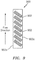
- the cooling channel 900 may include trip strips 902.
- the trip strips 902 may be similar to the trip strips 402 shown in conjunction with FIGS. 4A and 4D in the sense that the trip strips 902 may be composed of 'V'-shaped members (e.g., may be entirely composed of 'V'-shaped members in some embodiments).
- the trip strips 902 may differ from the trip strips 402 in that the trip strips 902 may assume a different orientation/angle relative to, e.g., the flow direction. For example, in comparing FIGS.
- the trip strips 902 (or more particularly, vertices of the members of the trip strips 902) are shown as being rotated/skewed clockwise by an angle of approximately forty-five degrees relative to the trip strips 402.
- the skew relative to the flow direction may be a value within a range of thirty degrees to sixty degrees.
- the trip strips 902 may be referred to as having a skewed-corrugated pattern.
- the trip strips 902 may cause a cooling flow (that is generally oriented in the direction of the flow direction superimposed in FIG. 9 ) to be steered towards the wall 903b (and away from the wall 903a).
- a cooling flow that is generally oriented in the direction of the flow direction superimposed in FIG. 9
- the configuration shown in FIG. 9 may find particular applicability in embodiments where cooling the wall 903b is of greater concern relative to the wall 903a.
- the cooling channel 1000 may include trip strips 1002.
- the trip strips 1002 may be similar to the trip strips 402 shown in conjunction with FIGS. 4A and 4D in the sense that the trip strips 1002 may be composed of members that include a pointed vertex/leading edge (where the leading edge is specified relative to the flow direction). The pointed vertex may help to split the flow, thereby reducing the likelihood of stagnation at the vertex.
- the trip strip legs 402-1 and 402-2 are shown as being linear in FIG. 4D
- the trip strips 1002 include curved legs in FIG. 10 .
- curved legs in FIG. 10 may gently/smoothly/gradually guide the converging flows together.
- a particular channel configuration (inclusive of a particular trip strip configuration) that is used may be based on one or more tests, simulations, computational fluid dynamics (CFD) analyses, etc., as would be understood by one of skill in the art based on a review of this disclosure.
- CFD computational fluid dynamics
- Various components of this disclosure may be composed of one or more materials.
- one or more metals e.g., nickel, steel, aluminum, titanium, etc.
- an airfoil inclusive of any walls that form the cooling channels.
- One or more techniques may be utilized to manufacture a component of this disclosure. For example, casting, machining, an application of one or more chemicals (e.g., chemical etching), additive manufacturing, etc., may be used.
- one or more chemicals e.g., chemical etching
- additive manufacturing etc.
- a channel may be used to increase a temperature of a component.
- a channel included in a component may convey a warm fluid (e.g., a fluid at a first temperature that is greater than a second temperature of the component) to de-ice/anti-ice the component.
Landscapes
- Engineering & Computer Science (AREA)
- Mechanical Engineering (AREA)
- General Engineering & Computer Science (AREA)
- Physics & Mathematics (AREA)
- Fluid Mechanics (AREA)
- Turbine Rotor Nozzle Sealing (AREA)
Claims (13)
- Schaufelprofil für ein Gasturbinentriebwerk, wobei das Schaufelprofil Folgendes umfasst:eine erste Wand (403, 503a, 603a) und eine zweite Wand (503b, 603b), die zumindest teilweise einen Kanal (400, 500, 600) definieren; wobei das Schaufelprofil ferner eine Kühlrippe (702) umfasst, die an die erste Wand (403, 503a, 603b) gekoppelt ist, wobei zumindest ein Teil der Kühlrippe (702) ein gewelltes Muster bildet, wobei das Schaufelprofil dadurch gekennzeichnet ist, dass die Kühlrippe (702) ein mittleres Element, das ein gerades Profil aufweist, und zusätzliche Elemente, die an das mittlere Element gekoppelt sind und ein 'V'-Profil aufweisen, umfasst, undwobei jedes zusätzliche Element einen ersten Schenkel (402-1) und einen zweiten Schenkel (402-2) beinhaltet.
- Schaufelprofil nach Anspruch 1, ferner umfassend eine Vielzahl von Kühlrippen, die an die erste Wand gekoppelt sind, wobei die Vielzahl von Kühlrippen die Kühlrippe beinhaltet.
- Schaufelprofil nach Anspruch 2, wobei zumindest ein Teil jeder der Vielzahl von Kühlrippen ein gewelltes Muster bildet.
- Schaufelprofil nach Anspruch 1, 2 oder 3, wobei der erste Schenkel (402-1) und der zweite Schenkel (402-2) einen Winkel zwischen ihnen definieren und wobei der Winkel geringer als neunzig Grad und größer als null Grad ist.
- Schaufelprofil nach einem der vorangehenden Ansprüche, ferner umfassend:eine zweite Kühlrippe, die an die zweite Wand (503b, 603b) gekoppelt ist,wobei die erste Wand (503a, 603a) und die zweite Wand (503b, 603b) einander gegenüberliegen.
- Schaufelprofil nach Anspruch 5, ferner umfassend:eine dritte Wand (603c) und eine vierte Wand (603d), die zumindest teilweise den Kanal (600) definieren;eine dritte Kühlrippe, die an die dritte Wand (603c) gekoppelt ist; undeine vierte Kühlrippe, die an die vierte Wand (603d) gekoppelt ist.
- Schaufelprofil nach einem der vorangehenden Ansprüche, wobei das gewellte Muster durch eine Vielzahl von Elementen definiert ist, die jeweils einen Scheitelpunkt (402-3) beinhalten, und wobei jeder der Scheitelpunkte (402-3) des gewellten Musters relativ zu einer Strömungsrichtung eines Fluids in dem Kanal schräg ist.
- Schaufelprofil nach Anspruch 7, wobei die Scheitelpunkte (402-3) um einen Winkel in einem Bereich von dreißig und sechzig Grad relativ zu der Strömungsrichtung schräg sind.
- Gasturbinentriebwerk, umfassend:einen Verdichterabschnitt (19);einen Brennkammerabschnitt (20); undeinen Turbinenabschnitt (21),wobei der Turbinenabschnitt (21) das Schaufelprofil nach einem der vorangehenden Ansprüche beinhaltet.
- Gasturbinentriebwerk nach Anspruch 9, wobei das Schaufelprofil Teil einer nicht rotierbaren Leitschaufel (228) oder einer rotierbaren Laufschaufel (214) ist.
- Gasturbinentriebwerk nach Anspruch 9 oder 10, wobei der Kanal (400, 500, 600) ein Fluid fördert, um die erste Wand (403, 503a, 603a) und die zweite Wand (503b, 603b) zu kühlen.
- Gasturbinentriebwerk nach Anspruch 11, wobei das Schaufelprofil eine zweite Kühlrippe beinhaltet, die an die erste Wand (403) gekoppelt ist, und wobei das Fluid beim Durchlaufen des Kanals zwischen der ersten Kühlrippe und der zweiten Kühlrippe konvergiert und divergiert.
- Gasturbinentriebwerk nach Anspruch 11 oder 12, wobei das Gasturbinentriebwerk ein Rohr (206) umfasst, das an den Verdichterabschnitt (19) und den Turbinenabschnitt (21) gekoppelt ist und das Fluid aus dem Verdichterabschnitt (19) zu dem Turbinenabschnitt (21) fördert.
Applications Claiming Priority (1)
| Application Number | Priority Date | Filing Date | Title |
|---|---|---|---|
| US16/012,300 US10815793B2 (en) | 2018-06-19 | 2018-06-19 | Trip strips for augmented boundary layer mixing |
Publications (2)
| Publication Number | Publication Date |
|---|---|
| EP3584407A1 EP3584407A1 (de) | 2019-12-25 |
| EP3584407B1 true EP3584407B1 (de) | 2021-11-03 |
Family
ID=66857673
Family Applications (1)
| Application Number | Title | Priority Date | Filing Date |
|---|---|---|---|
| EP19179785.1A Active EP3584407B1 (de) | 2018-06-19 | 2019-06-12 | Kühlrippen für erweiterte grenzschichtmischung |
Country Status (2)
| Country | Link |
|---|---|
| US (1) | US10815793B2 (de) |
| EP (1) | EP3584407B1 (de) |
Families Citing this family (3)
| Publication number | Priority date | Publication date | Assignee | Title |
|---|---|---|---|---|
| US10808552B2 (en) * | 2018-06-18 | 2020-10-20 | Raytheon Technologies Corporation | Trip strip configuration for gaspath component in a gas turbine engine |
| US12607125B2 (en) | 2021-02-05 | 2026-04-21 | Nikon Corporation | Blade member and structural member |
| EP4729742A1 (de) * | 2024-10-15 | 2026-04-22 | Industria de Turbo Propulsores, S.A.U. | Schaufelprofil, turbinenlaufschaufel, turbinenleitschaufel und turbinentriebwerk |
Family Cites Families (14)
| Publication number | Priority date | Publication date | Assignee | Title |
|---|---|---|---|---|
| US4627480A (en) * | 1983-11-07 | 1986-12-09 | General Electric Company | Angled turbulence promoter |
| US5052889A (en) * | 1990-05-17 | 1991-10-01 | Pratt & Whintey Canada | Offset ribs for heat transfer surface |
| DE19526917A1 (de) | 1995-07-22 | 1997-01-23 | Fiebig Martin Prof Dr Ing | Längswirbelerzeugende Rauhigkeitselemente |
| DE19963373A1 (de) * | 1999-12-28 | 2001-07-12 | Abb Alstom Power Ch Ag | Vorrichtung zur Kühlung einer, einen Strömungskanal umgebenden Strömungskanalwand mit wenigstens einem Rippenzug |
| DE10248548A1 (de) | 2002-10-18 | 2004-04-29 | Alstom (Switzerland) Ltd. | Kühlbares Bauteil |
| US7866947B2 (en) * | 2007-01-03 | 2011-01-11 | United Technologies Corporation | Turbine blade trip strip orientation |
| US8317474B1 (en) | 2010-01-19 | 2012-11-27 | Florida Turbine Technologies, Inc. | Turbine blade with near wall cooling |
| US20140219813A1 (en) * | 2012-09-14 | 2014-08-07 | Rafael A. Perez | Gas turbine engine serpentine cooling passage |
| EP2954168B1 (de) * | 2013-02-05 | 2019-07-03 | United Technologies Corporation | Gasturbinenmotorkomponente mit gekrümmtem turbulator |
| WO2014159800A1 (en) * | 2013-03-14 | 2014-10-02 | United Technologies Corporation | Obtuse angle chevron trip strip |
| US10156157B2 (en) * | 2015-02-13 | 2018-12-18 | United Technologies Corporation | S-shaped trip strips in internally cooled components |
| EP3124743B1 (de) * | 2015-07-28 | 2021-04-28 | Rolls-Royce Deutschland Ltd & Co KG | Leitschaufel und verfahren zur herstellung einer leitschaufel |
| WO2017171763A1 (en) * | 2016-03-31 | 2017-10-05 | Siemens Aktiengesellschaft | Turbine airfoil with turbulating feature on a cold wall |
| US10502068B2 (en) * | 2016-12-02 | 2019-12-10 | General Electric Company | Engine with chevron pin bank |
-
2018
- 2018-06-19 US US16/012,300 patent/US10815793B2/en active Active
-
2019
- 2019-06-12 EP EP19179785.1A patent/EP3584407B1/de active Active
Non-Patent Citations (1)
| Title |
|---|
| None * |
Also Published As
| Publication number | Publication date |
|---|---|
| EP3584407A1 (de) | 2019-12-25 |
| US20190383150A1 (en) | 2019-12-19 |
| US10815793B2 (en) | 2020-10-27 |
Similar Documents
| Publication | Publication Date | Title |
|---|---|---|
| US12565842B2 (en) | Airfoil having a film hole | |
| EP3121382B1 (de) | Gasturbinenmotoren mit kanalgekühlten haken zum halten eines teils relativ zu einer motorgehäusestruktur | |
| US10364681B2 (en) | Turbine blade | |
| US10443398B2 (en) | Turbine blade | |
| US7775053B2 (en) | Heat transfer augmentation in a compact heat exchanger pedestal array | |
| EP3553276B1 (de) | Gastrubinetriebwerks-rotor mit komponente zur umleitung des kühlmittelstroms | |
| US10066488B2 (en) | Turbomachine blade with generally radial cooling conduit to wheel space | |
| EP3584407B1 (de) | Kühlrippen für erweiterte grenzschichtmischung | |
| US20180171808A1 (en) | Turbine Engine Assembly with a Component having a Leading Edge Trough | |
| JP2017141825A (ja) | ガスタービンエンジン用の翼形部 | |
| US11085304B2 (en) | Variably skewed trip strips in internally cooled components | |
| US20180216467A1 (en) | Turbine engine with an extension into a buffer cavity | |
| EP2791472B1 (de) | Filmgekühlte turbinenkomponente | |
| US10590778B2 (en) | Engine component with non-uniform chevron pins | |
| US10502068B2 (en) | Engine with chevron pin bank | |
| CN107091122B (zh) | 具有冷却的涡轮发动机翼型件 | |
| US10428659B2 (en) | Crossover hole configuration for a flowpath component in a gas turbine engine | |
| CN107762564A (zh) | 带有多孔肋部的用于涡轮发动机的翼型件 | |
| CN115605668B (zh) | 涡轮机叶片 | |
| US10760427B2 (en) | Secondary flow control | |
| EP4450760A1 (de) | Anordnung für asymmetrische störstreifen, anordnung für asymmetrische störstreifen für ein bauteil für ein gasturbinentriebwerk und verfahren zum leiten einer fluidströmung durch einen strömungsdurchgang mit asymmetrischen störstreifen für ein bauteil eines gasturbinentriebwerks | |
| CN120608738A (zh) | 带有具有一组冷却导管的叶片组件的涡轮发动机 |
Legal Events
| Date | Code | Title | Description |
|---|---|---|---|
| PUAI | Public reference made under article 153(3) epc to a published international application that has entered the european phase |
Free format text: ORIGINAL CODE: 0009012 |
|
| STAA | Information on the status of an ep patent application or granted ep patent |
Free format text: STATUS: THE APPLICATION HAS BEEN PUBLISHED |
|
| AK | Designated contracting states |
Kind code of ref document: A1 Designated state(s): AL AT BE BG CH CY CZ DE DK EE ES FI FR GB GR HR HU IE IS IT LI LT LU LV MC MK MT NL NO PL PT RO RS SE SI SK SM TR |
|
| AX | Request for extension of the european patent |
Extension state: BA ME |
|
| STAA | Information on the status of an ep patent application or granted ep patent |
Free format text: STATUS: REQUEST FOR EXAMINATION WAS MADE |
|
| 17P | Request for examination filed |
Effective date: 20200623 |
|
| RBV | Designated contracting states (corrected) |
Designated state(s): AL AT BE BG CH CY CZ DE DK EE ES FI FR GB GR HR HU IE IS IT LI LT LU LV MC MK MT NL NO PL PT RO RS SE SI SK SM TR |
|
| STAA | Information on the status of an ep patent application or granted ep patent |
Free format text: STATUS: EXAMINATION IS IN PROGRESS |
|
| 17Q | First examination report despatched |
Effective date: 20200917 |
|
| RAP1 | Party data changed (applicant data changed or rights of an application transferred) |
Owner name: RAYTHEON TECHNOLOGIES CORPORATION |
|
| GRAP | Despatch of communication of intention to grant a patent |
Free format text: ORIGINAL CODE: EPIDOSNIGR1 |
|
| STAA | Information on the status of an ep patent application or granted ep patent |
Free format text: STATUS: GRANT OF PATENT IS INTENDED |
|
| INTG | Intention to grant announced |
Effective date: 20210521 |
|
| RIN1 | Information on inventor provided before grant (corrected) |
Inventor name: STYBORSKI, JEREMY Inventor name: STILLMAN, WILLIAM P. |
|
| GRAS | Grant fee paid |
Free format text: ORIGINAL CODE: EPIDOSNIGR3 |
|
| GRAA | (expected) grant |
Free format text: ORIGINAL CODE: 0009210 |
|
| STAA | Information on the status of an ep patent application or granted ep patent |
Free format text: STATUS: THE PATENT HAS BEEN GRANTED |
|
| AK | Designated contracting states |
Kind code of ref document: B1 Designated state(s): AL AT BE BG CH CY CZ DE DK EE ES FI FR GB GR HR HU IE IS IT LI LT LU LV MC MK MT NL NO PL PT RO RS SE SI SK SM TR |
|
| REG | Reference to a national code |
Ref country code: GB Ref legal event code: FG4D |
|
| REG | Reference to a national code |
Ref country code: AT Ref legal event code: REF Ref document number: 1444118 Country of ref document: AT Kind code of ref document: T Effective date: 20211115 Ref country code: CH Ref legal event code: EP |
|
| REG | Reference to a national code |
Ref country code: DE Ref legal event code: R096 Ref document number: 602019008856 Country of ref document: DE |
|
| REG | Reference to a national code |
Ref country code: IE Ref legal event code: FG4D |
|
| REG | Reference to a national code |
Ref country code: LT Ref legal event code: MG9D |
|
| REG | Reference to a national code |
Ref country code: NL Ref legal event code: MP Effective date: 20211103 |
|
| REG | Reference to a national code |
Ref country code: AT Ref legal event code: MK05 Ref document number: 1444118 Country of ref document: AT Kind code of ref document: T Effective date: 20211103 |
|
| PG25 | Lapsed in a contracting state [announced via postgrant information from national office to epo] |
Ref country code: RS Free format text: LAPSE BECAUSE OF FAILURE TO SUBMIT A TRANSLATION OF THE DESCRIPTION OR TO PAY THE FEE WITHIN THE PRESCRIBED TIME-LIMIT Effective date: 20211103 Ref country code: LT Free format text: LAPSE BECAUSE OF FAILURE TO SUBMIT A TRANSLATION OF THE DESCRIPTION OR TO PAY THE FEE WITHIN THE PRESCRIBED TIME-LIMIT Effective date: 20211103 Ref country code: FI Free format text: LAPSE BECAUSE OF FAILURE TO SUBMIT A TRANSLATION OF THE DESCRIPTION OR TO PAY THE FEE WITHIN THE PRESCRIBED TIME-LIMIT Effective date: 20211103 Ref country code: BG Free format text: LAPSE BECAUSE OF FAILURE TO SUBMIT A TRANSLATION OF THE DESCRIPTION OR TO PAY THE FEE WITHIN THE PRESCRIBED TIME-LIMIT Effective date: 20220203 Ref country code: AT Free format text: LAPSE BECAUSE OF FAILURE TO SUBMIT A TRANSLATION OF THE DESCRIPTION OR TO PAY THE FEE WITHIN THE PRESCRIBED TIME-LIMIT Effective date: 20211103 |
|
| PG25 | Lapsed in a contracting state [announced via postgrant information from national office to epo] |
Ref country code: IS Free format text: LAPSE BECAUSE OF FAILURE TO SUBMIT A TRANSLATION OF THE DESCRIPTION OR TO PAY THE FEE WITHIN THE PRESCRIBED TIME-LIMIT Effective date: 20220303 Ref country code: SE Free format text: LAPSE BECAUSE OF FAILURE TO SUBMIT A TRANSLATION OF THE DESCRIPTION OR TO PAY THE FEE WITHIN THE PRESCRIBED TIME-LIMIT Effective date: 20211103 Ref country code: PT Free format text: LAPSE BECAUSE OF FAILURE TO SUBMIT A TRANSLATION OF THE DESCRIPTION OR TO PAY THE FEE WITHIN THE PRESCRIBED TIME-LIMIT Effective date: 20220303 Ref country code: PL Free format text: LAPSE BECAUSE OF FAILURE TO SUBMIT A TRANSLATION OF THE DESCRIPTION OR TO PAY THE FEE WITHIN THE PRESCRIBED TIME-LIMIT Effective date: 20211103 Ref country code: NO Free format text: LAPSE BECAUSE OF FAILURE TO SUBMIT A TRANSLATION OF THE DESCRIPTION OR TO PAY THE FEE WITHIN THE PRESCRIBED TIME-LIMIT Effective date: 20220203 Ref country code: NL Free format text: LAPSE BECAUSE OF FAILURE TO SUBMIT A TRANSLATION OF THE DESCRIPTION OR TO PAY THE FEE WITHIN THE PRESCRIBED TIME-LIMIT Effective date: 20211103 Ref country code: LV Free format text: LAPSE BECAUSE OF FAILURE TO SUBMIT A TRANSLATION OF THE DESCRIPTION OR TO PAY THE FEE WITHIN THE PRESCRIBED TIME-LIMIT Effective date: 20211103 Ref country code: HR Free format text: LAPSE BECAUSE OF FAILURE TO SUBMIT A TRANSLATION OF THE DESCRIPTION OR TO PAY THE FEE WITHIN THE PRESCRIBED TIME-LIMIT Effective date: 20211103 Ref country code: GR Free format text: LAPSE BECAUSE OF FAILURE TO SUBMIT A TRANSLATION OF THE DESCRIPTION OR TO PAY THE FEE WITHIN THE PRESCRIBED TIME-LIMIT Effective date: 20220204 Ref country code: ES Free format text: LAPSE BECAUSE OF FAILURE TO SUBMIT A TRANSLATION OF THE DESCRIPTION OR TO PAY THE FEE WITHIN THE PRESCRIBED TIME-LIMIT Effective date: 20211103 |
|
| PG25 | Lapsed in a contracting state [announced via postgrant information from national office to epo] |
Ref country code: SM Free format text: LAPSE BECAUSE OF FAILURE TO SUBMIT A TRANSLATION OF THE DESCRIPTION OR TO PAY THE FEE WITHIN THE PRESCRIBED TIME-LIMIT Effective date: 20211103 Ref country code: SK Free format text: LAPSE BECAUSE OF FAILURE TO SUBMIT A TRANSLATION OF THE DESCRIPTION OR TO PAY THE FEE WITHIN THE PRESCRIBED TIME-LIMIT Effective date: 20211103 Ref country code: RO Free format text: LAPSE BECAUSE OF FAILURE TO SUBMIT A TRANSLATION OF THE DESCRIPTION OR TO PAY THE FEE WITHIN THE PRESCRIBED TIME-LIMIT Effective date: 20211103 Ref country code: EE Free format text: LAPSE BECAUSE OF FAILURE TO SUBMIT A TRANSLATION OF THE DESCRIPTION OR TO PAY THE FEE WITHIN THE PRESCRIBED TIME-LIMIT Effective date: 20211103 Ref country code: DK Free format text: LAPSE BECAUSE OF FAILURE TO SUBMIT A TRANSLATION OF THE DESCRIPTION OR TO PAY THE FEE WITHIN THE PRESCRIBED TIME-LIMIT Effective date: 20211103 Ref country code: CZ Free format text: LAPSE BECAUSE OF FAILURE TO SUBMIT A TRANSLATION OF THE DESCRIPTION OR TO PAY THE FEE WITHIN THE PRESCRIBED TIME-LIMIT Effective date: 20211103 |
|
| REG | Reference to a national code |
Ref country code: DE Ref legal event code: R097 Ref document number: 602019008856 Country of ref document: DE |
|
| PLBE | No opposition filed within time limit |
Free format text: ORIGINAL CODE: 0009261 |
|
| STAA | Information on the status of an ep patent application or granted ep patent |
Free format text: STATUS: NO OPPOSITION FILED WITHIN TIME LIMIT |
|
| 26N | No opposition filed |
Effective date: 20220804 |
|
| PG25 | Lapsed in a contracting state [announced via postgrant information from national office to epo] |
Ref country code: AL Free format text: LAPSE BECAUSE OF FAILURE TO SUBMIT A TRANSLATION OF THE DESCRIPTION OR TO PAY THE FEE WITHIN THE PRESCRIBED TIME-LIMIT Effective date: 20211103 |
|
| PG25 | Lapsed in a contracting state [announced via postgrant information from national office to epo] |
Ref country code: SI Free format text: LAPSE BECAUSE OF FAILURE TO SUBMIT A TRANSLATION OF THE DESCRIPTION OR TO PAY THE FEE WITHIN THE PRESCRIBED TIME-LIMIT Effective date: 20211103 |
|
| PG25 | Lapsed in a contracting state [announced via postgrant information from national office to epo] |
Ref country code: MC Free format text: LAPSE BECAUSE OF FAILURE TO SUBMIT A TRANSLATION OF THE DESCRIPTION OR TO PAY THE FEE WITHIN THE PRESCRIBED TIME-LIMIT Effective date: 20211103 |
|
| REG | Reference to a national code |
Ref country code: CH Ref legal event code: PL |
|
| REG | Reference to a national code |
Ref country code: BE Ref legal event code: MM Effective date: 20220630 |
|
| PG25 | Lapsed in a contracting state [announced via postgrant information from national office to epo] |
Ref country code: LU Free format text: LAPSE BECAUSE OF NON-PAYMENT OF DUE FEES Effective date: 20220612 Ref country code: LI Free format text: LAPSE BECAUSE OF NON-PAYMENT OF DUE FEES Effective date: 20220630 Ref country code: IE Free format text: LAPSE BECAUSE OF NON-PAYMENT OF DUE FEES Effective date: 20220612 Ref country code: CH Free format text: LAPSE BECAUSE OF NON-PAYMENT OF DUE FEES Effective date: 20220630 |
|
| PG25 | Lapsed in a contracting state [announced via postgrant information from national office to epo] |
Ref country code: IT Free format text: LAPSE BECAUSE OF FAILURE TO SUBMIT A TRANSLATION OF THE DESCRIPTION OR TO PAY THE FEE WITHIN THE PRESCRIBED TIME-LIMIT Effective date: 20211103 Ref country code: BE Free format text: LAPSE BECAUSE OF NON-PAYMENT OF DUE FEES Effective date: 20220630 |
|
| P01 | Opt-out of the competence of the unified patent court (upc) registered |
Effective date: 20230521 |
|
| PG25 | Lapsed in a contracting state [announced via postgrant information from national office to epo] |
Ref country code: MK Free format text: LAPSE BECAUSE OF FAILURE TO SUBMIT A TRANSLATION OF THE DESCRIPTION OR TO PAY THE FEE WITHIN THE PRESCRIBED TIME-LIMIT Effective date: 20211103 Ref country code: CY Free format text: LAPSE BECAUSE OF FAILURE TO SUBMIT A TRANSLATION OF THE DESCRIPTION OR TO PAY THE FEE WITHIN THE PRESCRIBED TIME-LIMIT Effective date: 20211103 |
|
| PG25 | Lapsed in a contracting state [announced via postgrant information from national office to epo] |
Ref country code: HU Free format text: LAPSE BECAUSE OF FAILURE TO SUBMIT A TRANSLATION OF THE DESCRIPTION OR TO PAY THE FEE WITHIN THE PRESCRIBED TIME-LIMIT; INVALID AB INITIO Effective date: 20190612 |
|
| PG25 | Lapsed in a contracting state [announced via postgrant information from national office to epo] |
Ref country code: MT Free format text: LAPSE BECAUSE OF FAILURE TO SUBMIT A TRANSLATION OF THE DESCRIPTION OR TO PAY THE FEE WITHIN THE PRESCRIBED TIME-LIMIT Effective date: 20211103 |
|
| PGFP | Annual fee paid to national office [announced via postgrant information from national office to epo] |
Ref country code: DE Payment date: 20250520 Year of fee payment: 7 |
|
| PGFP | Annual fee paid to national office [announced via postgrant information from national office to epo] |
Ref country code: GB Payment date: 20250520 Year of fee payment: 7 |
|
| PGFP | Annual fee paid to national office [announced via postgrant information from national office to epo] |
Ref country code: FR Payment date: 20250520 Year of fee payment: 7 |
|
| REG | Reference to a national code |
Ref country code: DE Ref legal event code: R081 Ref document number: 602019008856 Country of ref document: DE Owner name: RTX CORPORATION (N.D.GES.D. STAATES DELAWARE),, US Free format text: FORMER OWNER: RAYTHEON TECHNOLOGIES CORPORATION, FARMINGTON, CT, US |
|
| PG25 | Lapsed in a contracting state [announced via postgrant information from national office to epo] |
Ref country code: TR Free format text: LAPSE BECAUSE OF FAILURE TO SUBMIT A TRANSLATION OF THE DESCRIPTION OR TO PAY THE FEE WITHIN THE PRESCRIBED TIME-LIMIT Effective date: 20211103 |