EP3584452B1 - Composant résineux - Google Patents
Composant résineux Download PDFInfo
- Publication number
- EP3584452B1 EP3584452B1 EP18753644.6A EP18753644A EP3584452B1 EP 3584452 B1 EP3584452 B1 EP 3584452B1 EP 18753644 A EP18753644 A EP 18753644A EP 3584452 B1 EP3584452 B1 EP 3584452B1
- Authority
- EP
- European Patent Office
- Prior art keywords
- housing
- adhesive
- cover
- insertion protrusion
- groove
- Prior art date
- Legal status (The legal status is an assumption and is not a legal conclusion. Google has not performed a legal analysis and makes no representation as to the accuracy of the status listed.)
- Active
Links
Images




Classifications
-
- F—MECHANICAL ENGINEERING; LIGHTING; HEATING; WEAPONS; BLASTING
- F16—ENGINEERING ELEMENTS AND UNITS; GENERAL MEASURES FOR PRODUCING AND MAINTAINING EFFECTIVE FUNCTIONING OF MACHINES OR INSTALLATIONS; THERMAL INSULATION IN GENERAL
- F16B—DEVICES FOR FASTENING OR SECURING CONSTRUCTIONAL ELEMENTS OR MACHINE PARTS TOGETHER, e.g. NAILS, BOLTS, CIRCLIPS, CLAMPS, CLIPS OR WEDGES; JOINTS OR JOINTING
- F16B11/00—Connecting constructional elements or machine parts by sticking or pressing them together, e.g. cold pressure welding
- F16B11/006—Connecting constructional elements or machine parts by sticking or pressing them together, e.g. cold pressure welding by gluing
-
- B—PERFORMING OPERATIONS; TRANSPORTING
- B29—WORKING OF PLASTICS; WORKING OF SUBSTANCES IN A PLASTIC STATE IN GENERAL
- B29C—SHAPING OR JOINING OF PLASTICS; SHAPING OF MATERIAL IN A PLASTIC STATE, NOT OTHERWISE PROVIDED FOR; AFTER-TREATMENT OF THE SHAPED PRODUCTS, e.g. REPAIRING
- B29C65/00—Joining or sealing of preformed parts, e.g. welding of plastics materials; Apparatus therefor
- B29C65/48—Joining or sealing of preformed parts, e.g. welding of plastics materials; Apparatus therefor using adhesives, i.e. using supplementary joining material; solvent bonding
-
- B—PERFORMING OPERATIONS; TRANSPORTING
- B29—WORKING OF PLASTICS; WORKING OF SUBSTANCES IN A PLASTIC STATE IN GENERAL
- B29C—SHAPING OR JOINING OF PLASTICS; SHAPING OF MATERIAL IN A PLASTIC STATE, NOT OTHERWISE PROVIDED FOR; AFTER-TREATMENT OF THE SHAPED PRODUCTS, e.g. REPAIRING
- B29C65/00—Joining or sealing of preformed parts, e.g. welding of plastics materials; Apparatus therefor
- B29C65/56—Joining or sealing of preformed parts, e.g. welding of plastics materials; Apparatus therefor using mechanical means or mechanical connections, e.g. form-fits
- B29C65/58—Snap connection
-
- B—PERFORMING OPERATIONS; TRANSPORTING
- B29—WORKING OF PLASTICS; WORKING OF SUBSTANCES IN A PLASTIC STATE IN GENERAL
- B29C—SHAPING OR JOINING OF PLASTICS; SHAPING OF MATERIAL IN A PLASTIC STATE, NOT OTHERWISE PROVIDED FOR; AFTER-TREATMENT OF THE SHAPED PRODUCTS, e.g. REPAIRING
- B29C65/00—Joining or sealing of preformed parts, e.g. welding of plastics materials; Apparatus therefor
- B29C65/72—Joining or sealing of preformed parts, e.g. welding of plastics materials; Apparatus therefor by combined operations or combined techniques, e.g. welding and stitching
-
- B—PERFORMING OPERATIONS; TRANSPORTING
- B29—WORKING OF PLASTICS; WORKING OF SUBSTANCES IN A PLASTIC STATE IN GENERAL
- B29C—SHAPING OR JOINING OF PLASTICS; SHAPING OF MATERIAL IN A PLASTIC STATE, NOT OTHERWISE PROVIDED FOR; AFTER-TREATMENT OF THE SHAPED PRODUCTS, e.g. REPAIRING
- B29C65/00—Joining or sealing of preformed parts, e.g. welding of plastics materials; Apparatus therefor
- B29C65/78—Means for handling the parts to be joined, e.g. for making containers or hollow articles, e.g. means for handling sheets, plates, web-like materials, tubular articles, hollow articles or elements to be joined therewith; Means for discharging the joined articles from the joining apparatus
- B29C65/7802—Positioning the parts to be joined, e.g. aligning, indexing or centring
- B29C65/782—Positioning the parts to be joined, e.g. aligning, indexing or centring by setting the gap between the parts to be joined
- B29C65/7823—Positioning the parts to be joined, e.g. aligning, indexing or centring by setting the gap between the parts to be joined by using distance pieces, i.e. by using spacers positioned between the parts to be joined and forming a part of the joint
- B29C65/7829—Positioning the parts to be joined, e.g. aligning, indexing or centring by setting the gap between the parts to be joined by using distance pieces, i.e. by using spacers positioned between the parts to be joined and forming a part of the joint said distance pieces being integral with at least one of the parts to be joined
-
- B—PERFORMING OPERATIONS; TRANSPORTING
- B29—WORKING OF PLASTICS; WORKING OF SUBSTANCES IN A PLASTIC STATE IN GENERAL
- B29C—SHAPING OR JOINING OF PLASTICS; SHAPING OF MATERIAL IN A PLASTIC STATE, NOT OTHERWISE PROVIDED FOR; AFTER-TREATMENT OF THE SHAPED PRODUCTS, e.g. REPAIRING
- B29C65/00—Joining or sealing of preformed parts, e.g. welding of plastics materials; Apparatus therefor
- B29C65/78—Means for handling the parts to be joined, e.g. for making containers or hollow articles, e.g. means for handling sheets, plates, web-like materials, tubular articles, hollow articles or elements to be joined therewith; Means for discharging the joined articles from the joining apparatus
- B29C65/7855—Provisory fixing
-
- B—PERFORMING OPERATIONS; TRANSPORTING
- B29—WORKING OF PLASTICS; WORKING OF SUBSTANCES IN A PLASTIC STATE IN GENERAL
- B29C—SHAPING OR JOINING OF PLASTICS; SHAPING OF MATERIAL IN A PLASTIC STATE, NOT OTHERWISE PROVIDED FOR; AFTER-TREATMENT OF THE SHAPED PRODUCTS, e.g. REPAIRING
- B29C66/00—General aspects of processes or apparatus for joining preformed parts
- B29C66/01—General aspects dealing with the joint area or with the area to be joined
- B29C66/05—Particular design of joint configurations
- B29C66/10—Particular design of joint configurations particular design of the joint cross-sections
- B29C66/11—Joint cross-sections comprising a single joint-segment, i.e. one of the parts to be joined comprising a single joint-segment in the joint cross-section
- B29C66/112—Single lapped joints
-
- B—PERFORMING OPERATIONS; TRANSPORTING
- B29—WORKING OF PLASTICS; WORKING OF SUBSTANCES IN A PLASTIC STATE IN GENERAL
- B29C—SHAPING OR JOINING OF PLASTICS; SHAPING OF MATERIAL IN A PLASTIC STATE, NOT OTHERWISE PROVIDED FOR; AFTER-TREATMENT OF THE SHAPED PRODUCTS, e.g. REPAIRING
- B29C66/00—General aspects of processes or apparatus for joining preformed parts
- B29C66/01—General aspects dealing with the joint area or with the area to be joined
- B29C66/05—Particular design of joint configurations
- B29C66/10—Particular design of joint configurations particular design of the joint cross-sections
- B29C66/12—Joint cross-sections combining only two joint-segments; Tongue and groove joints; Tenon and mortise joints; Stepped joint cross-sections
- B29C66/124—Tongue and groove joints
- B29C66/1244—Tongue and groove joints characterised by the male part, i.e. the part comprising the tongue
- B29C66/12445—Tongue and groove joints characterised by the male part, i.e. the part comprising the tongue having the tongue on the side
-
- B—PERFORMING OPERATIONS; TRANSPORTING
- B29—WORKING OF PLASTICS; WORKING OF SUBSTANCES IN A PLASTIC STATE IN GENERAL
- B29C—SHAPING OR JOINING OF PLASTICS; SHAPING OF MATERIAL IN A PLASTIC STATE, NOT OTHERWISE PROVIDED FOR; AFTER-TREATMENT OF THE SHAPED PRODUCTS, e.g. REPAIRING
- B29C66/00—General aspects of processes or apparatus for joining preformed parts
- B29C66/01—General aspects dealing with the joint area or with the area to be joined
- B29C66/05—Particular design of joint configurations
- B29C66/10—Particular design of joint configurations particular design of the joint cross-sections
- B29C66/12—Joint cross-sections combining only two joint-segments; Tongue and groove joints; Tenon and mortise joints; Stepped joint cross-sections
- B29C66/124—Tongue and groove joints
- B29C66/1246—Tongue and groove joints characterised by the female part, i.e. the part comprising the groove
- B29C66/12469—Tongue and groove joints characterised by the female part, i.e. the part comprising the groove being asymmetric
-
- B—PERFORMING OPERATIONS; TRANSPORTING
- B29—WORKING OF PLASTICS; WORKING OF SUBSTANCES IN A PLASTIC STATE IN GENERAL
- B29C—SHAPING OR JOINING OF PLASTICS; SHAPING OF MATERIAL IN A PLASTIC STATE, NOT OTHERWISE PROVIDED FOR; AFTER-TREATMENT OF THE SHAPED PRODUCTS, e.g. REPAIRING
- B29C66/00—General aspects of processes or apparatus for joining preformed parts
- B29C66/01—General aspects dealing with the joint area or with the area to be joined
- B29C66/05—Particular design of joint configurations
- B29C66/10—Particular design of joint configurations particular design of the joint cross-sections
- B29C66/13—Single flanged joints; Fin-type joints; Single hem joints; Edge joints; Interpenetrating fingered joints; Other specific particular designs of joint cross-sections not provided for in groups B29C66/11 - B29C66/12
- B29C66/131—Single flanged joints, i.e. one of the parts to be joined being rigid and flanged in the joint area
-
- B—PERFORMING OPERATIONS; TRANSPORTING
- B29—WORKING OF PLASTICS; WORKING OF SUBSTANCES IN A PLASTIC STATE IN GENERAL
- B29C—SHAPING OR JOINING OF PLASTICS; SHAPING OF MATERIAL IN A PLASTIC STATE, NOT OTHERWISE PROVIDED FOR; AFTER-TREATMENT OF THE SHAPED PRODUCTS, e.g. REPAIRING
- B29C66/00—General aspects of processes or apparatus for joining preformed parts
- B29C66/01—General aspects dealing with the joint area or with the area to be joined
- B29C66/05—Particular design of joint configurations
- B29C66/303—Particular design of joint configurations the joint involving an anchoring effect
- B29C66/3032—Particular design of joint configurations the joint involving an anchoring effect making use of protrusions or cavities belonging to at least one of the parts to be joined
- B29C66/30321—Particular design of joint configurations the joint involving an anchoring effect making use of protrusions or cavities belonging to at least one of the parts to be joined making use of protrusions belonging to at least one of the parts to be joined
- B29C66/30322—Particular design of joint configurations the joint involving an anchoring effect making use of protrusions or cavities belonging to at least one of the parts to be joined making use of protrusions belonging to at least one of the parts to be joined in the form of rugosity
-
- B—PERFORMING OPERATIONS; TRANSPORTING
- B29—WORKING OF PLASTICS; WORKING OF SUBSTANCES IN A PLASTIC STATE IN GENERAL
- B29C—SHAPING OR JOINING OF PLASTICS; SHAPING OF MATERIAL IN A PLASTIC STATE, NOT OTHERWISE PROVIDED FOR; AFTER-TREATMENT OF THE SHAPED PRODUCTS, e.g. REPAIRING
- B29C66/00—General aspects of processes or apparatus for joining preformed parts
- B29C66/01—General aspects dealing with the joint area or with the area to be joined
- B29C66/32—Measures for keeping the burr form under control; Avoiding burr formation; Shaping the burr
- B29C66/322—Providing cavities in the joined article to collect the burr
-
- B—PERFORMING OPERATIONS; TRANSPORTING
- B29—WORKING OF PLASTICS; WORKING OF SUBSTANCES IN A PLASTIC STATE IN GENERAL
- B29C—SHAPING OR JOINING OF PLASTICS; SHAPING OF MATERIAL IN A PLASTIC STATE, NOT OTHERWISE PROVIDED FOR; AFTER-TREATMENT OF THE SHAPED PRODUCTS, e.g. REPAIRING
- B29C66/00—General aspects of processes or apparatus for joining preformed parts
- B29C66/50—General aspects of joining tubular articles; General aspects of joining long products, i.e. bars or profiled elements; General aspects of joining single elements to tubular articles, hollow articles or bars; General aspects of joining several hollow-preforms to form hollow or tubular articles
- B29C66/51—Joining tubular articles, profiled elements or bars; Joining single elements to tubular articles, hollow articles or bars; Joining several hollow-preforms to form hollow or tubular articles
- B29C66/54—Joining several hollow-preforms, e.g. half-shells, to form hollow articles, e.g. for making balls, containers; Joining several hollow-preforms, e.g. half-cylinders, to form tubular articles
- B29C66/542—Joining several hollow-preforms, e.g. half-shells, to form hollow articles, e.g. for making balls, containers; Joining several hollow-preforms, e.g. half-cylinders, to form tubular articles joining hollow covers or hollow bottoms to open ends of container bodies
-
- B—PERFORMING OPERATIONS; TRANSPORTING
- B29—WORKING OF PLASTICS; WORKING OF SUBSTANCES IN A PLASTIC STATE IN GENERAL
- B29C—SHAPING OR JOINING OF PLASTICS; SHAPING OF MATERIAL IN A PLASTIC STATE, NOT OTHERWISE PROVIDED FOR; AFTER-TREATMENT OF THE SHAPED PRODUCTS, e.g. REPAIRING
- B29C66/00—General aspects of processes or apparatus for joining preformed parts
- B29C66/50—General aspects of joining tubular articles; General aspects of joining long products, i.e. bars or profiled elements; General aspects of joining single elements to tubular articles, hollow articles or bars; General aspects of joining several hollow-preforms to form hollow or tubular articles
- B29C66/51—Joining tubular articles, profiled elements or bars; Joining single elements to tubular articles, hollow articles or bars; Joining several hollow-preforms to form hollow or tubular articles
- B29C66/54—Joining several hollow-preforms, e.g. half-shells, to form hollow articles, e.g. for making balls, containers; Joining several hollow-preforms, e.g. half-cylinders, to form tubular articles
- B29C66/543—Joining several hollow-preforms, e.g. half-shells, to form hollow articles, e.g. for making balls, containers; Joining several hollow-preforms, e.g. half-cylinders, to form tubular articles joining more than two hollow-preforms to form said hollow articles
-
- B—PERFORMING OPERATIONS; TRANSPORTING
- B60—VEHICLES IN GENERAL
- B60T—VEHICLE BRAKE CONTROL SYSTEMS OR PARTS THEREOF; BRAKE CONTROL SYSTEMS OR PARTS THEREOF, IN GENERAL; ARRANGEMENT OF BRAKING ELEMENTS ON VEHICLES IN GENERAL; PORTABLE DEVICES FOR PREVENTING UNWANTED MOVEMENT OF VEHICLES; VEHICLE MODIFICATIONS TO FACILITATE COOLING OF BRAKES
- B60T8/00—Arrangements for adjusting wheel-braking force to meet varying vehicular or ground-surface conditions, e.g. limiting or varying distribution of braking force
- B60T8/32—Arrangements for adjusting wheel-braking force to meet varying vehicular or ground-surface conditions, e.g. limiting or varying distribution of braking force responsive to a speed condition, e.g. acceleration or deceleration
- B60T8/34—Arrangements for adjusting wheel-braking force to meet varying vehicular or ground-surface conditions, e.g. limiting or varying distribution of braking force responsive to a speed condition, e.g. acceleration or deceleration having a fluid pressure regulator responsive to a speed condition
- B60T8/343—Systems characterised by their lay-out
-
- H—ELECTRICITY
- H02—GENERATION; CONVERSION OR DISTRIBUTION OF ELECTRIC POWER
- H02G—INSTALLATION OF ELECTRIC CABLES OR LINES, OR OF COMBINED OPTICAL AND ELECTRIC CABLES OR LINES
- H02G3/00—Installations of electric cables or lines or protective tubing therefor in or on buildings, equivalent structures or vehicles
- H02G3/02—Details
- H02G3/08—Distribution boxes; Connection or junction boxes
- H02G3/088—Dustproof, splashproof, drip-proof, waterproof, or flameproof casings or inlets
-
- H—ELECTRICITY
- H02—GENERATION; CONVERSION OR DISTRIBUTION OF ELECTRIC POWER
- H02G—INSTALLATION OF ELECTRIC CABLES OR LINES, OR OF COMBINED OPTICAL AND ELECTRIC CABLES OR LINES
- H02G3/00—Installations of electric cables or lines or protective tubing therefor in or on buildings, equivalent structures or vehicles
- H02G3/02—Details
- H02G3/08—Distribution boxes; Connection or junction boxes
- H02G3/14—Fastening of cover or lid to box
-
- B—PERFORMING OPERATIONS; TRANSPORTING
- B29—WORKING OF PLASTICS; WORKING OF SUBSTANCES IN A PLASTIC STATE IN GENERAL
- B29L—INDEXING SCHEME ASSOCIATED WITH SUBCLASS B29C, RELATING TO PARTICULAR ARTICLES
- B29L2031/00—Other particular articles
- B29L2031/34—Electrical apparatus, e.g. sparking plugs or parts thereof
- B29L2031/3481—Housings or casings incorporating or embedding electric or electronic elements
-
- H—ELECTRICITY
- H02—GENERATION; CONVERSION OR DISTRIBUTION OF ELECTRIC POWER
- H02G—INSTALLATION OF ELECTRIC CABLES OR LINES, OR OF COMBINED OPTICAL AND ELECTRIC CABLES OR LINES
- H02G3/00—Installations of electric cables or lines or protective tubing therefor in or on buildings, equivalent structures or vehicles
- H02G3/02—Details
- H02G3/08—Distribution boxes; Connection or junction boxes
- H02G3/16—Distribution boxes; Connection or junction boxes structurally associated with support for line-connecting terminals within the box
Definitions
- the present invention relates to a resinous component that prevents an adhesive from entering an inside thereof.
- a control device that includes a base body, a housing attached to the base body, and a cover attached to the housing is known.
- drip-proof treatment is applied to a fixing portion between the housing and the base body and an attachment portion between the housing and the cover to prevent water or the like from entering the inside through the fixing portion and the attachment portion.
- an annular groove is provided in the housing and an adhesive is applied as a drip-proof treatment.
- an adhesive When an adhesive is applied to a groove shape as described in PTL 1, an adhesive may protrude onto the inner surface of the housing during assembly and the adhesive may enter the inside of the housing.
- a resinous housing accommodates a control board and electric components that are precision parts, it is necessary to prevent the adhesive from entering the inside of the housing so as not to affect these components.
- the technique disclosed in Japanese Patent No. 4520915 (referred to below as PTL 2) is present as the sealing structure of a control device.
- a groove is provided in a part of a housing close to a base body and this groove is filled with a sealing agent.
- PTL 4 the technique disclosed in JP-A-2014-184744 (referred to below as PTL 4) is present.
- a seal is provided between a base body and a housing and the seal is provided in a sealing groove formed in the housing.
- interface peeling may occur between the housing and the adhesive and sealing effects may not be exerted sufficiently.
- JP 2013-115276 A describes a metal substrate which has conductor wiring which is formed, via an insulator layer made of resin, on a top face of a base made of metal.
- a mold case houses the metal substrate and electronic components, and a bus bar and a terminal for electrical connection to the outside are insert-molded therein.
- the metal substrate is configured such that the metal base constituted by a conductive member does not come into contact with a grounded conductive member around a vehicle and is bonded and fixed to the mold case constituted by an insulation member, while the base of the metal substrate is electrically ungrounded.
- the metal substrate is bonded and fixed to an end face of the mold case, and the base surface of the metal substrate is exposed to the atmosphere outside the mold case.
- JP 2014-061629 A describes a decorative body with rhinestones made by bonding a plurality of rhinestones on a substrate.
- the decorative body is constructed by: forming rough surfaces corresponding to sizes and shapes of the rhinestones in a predetermined layout on a surface of the substrate by laser processing; forming contour grooves having a processed depth deeper than the rough surfaces at the edges of the rough surfaces; and placing and bonding the rhinestones on the rough surfaces.
- JP 2014-086644 A describes a waterproof structure of a housing for incorporating an electronic component which includes a housing consisting of a first case, and a second case having a groove to be applied with an adhesive in the surface facing the first case, and an electronic component to be incorporated in the housing.
- the first case is provided, in the surface facing the second case, with a protrusion which comes into contact with the adhesive by intruding into the groove, when the first case and second case are attached to the surface facing the second case.
- US 2002/0122302 A1 describes a night vision binocular assembly capable of converting low light and infrared energy into a visible image.
- the night vision binocular assembly includes at least one objective lens assembly, image intensifier tube, collimator lens assembly and diopter cell assembly encased in an easy to assemble waterproof housing.
- An object of the invention is to provide a resinous component having a structure that prevents an adhesive from entering the inside of a housing.
- the adhesive When the housing is assembled to the base body, the adhesive enters the small gap. Since the excess portion of the adhesive is collected in the small gap, there is no concern that the adhesive enters the inside of the housing.
- An anchor effect of putting the adhesive onto the coarse surface is exerted. This anchor effect prevents the adhesive from peeling from the surface of the lower groove, thereby improving the bonding performance of the adhesive.
- the adhesive is surely attached to the insertion protrusion of the cover.
- the inner-side gap on the inner side of the insertion protrusion is larger than the outer-side gap on the outer side of the insertion protrusion, the adhesive can be collected in the inner-side gap. As a result, it is possible to prevent the adhesive from entering the inside of the housing.
- the projection provided on the insertion protrusion comes in contact with the outer-side wall surface of the top groove, so it is possible to prevent a rattle when the cover is attached to the housing.
- a control device that controls the fluid pressures of a front wheel brake and a rear wheel brake is referred to as a dual-circuit vehicle brake fluid pressure control device and a control device that controls the fluid pressure of one of the front wheel brake and the rear wheel brake is referred to as a single-circuit vehicle brake fluid pressure control device.
- a dual-circuit vehicle brake fluid pressure control device 10 includes a first master cylinder 12, a first reservoir 13, a first inlet control valve 15 that is a normally open solenoid valve, a first outlet control valve 16 that is a normally closed solenoid valve, a first pump 17, a second master cylinder 22, a second reservoir 23, a second inlet control valve 25 that is a normally open solenoid valve, a second outlet control valve 26 that is a normally closed solenoid valve, a second pump 27, a motor 29 that drives the first and second pumps 17 and 27, a control device 30 that controls the driving of the motor 29 and controls the opening and closing of the first and second inlet control valves 15 and 25 and the first and second outlet control valves 16 and 26, brake fluid lines A1, B1, C1, D1, and E1 of a first circuit and brake fluid lines A2, B2, C2, D2, and E2 of a second circuit that are provided in a base body 40 and through which a brake fluid flows.
- the first master cylinder 12 pressurizes a hydraulic fluid in accordance with an operation of a brake lever 11 to produce a fluid pressure.
- the first reservoir 13 temporarily reserves the hydraulic fluid released from a front wheel brake caliper 14.
- the first inlet valve 15 and the first outlet control valve 16 are assembly components provided between the first master cylinder 12 and the front wheel brake caliper 14.
- the first pump 17 is an assembly component that sucks the hydraulic fluid reserved in the first reservoir 13 and returns the hydraulic fluid to the first master cylinder 12.
- the second master cylinder 22 pressurizes the hydraulic fluid in accordance with an operation of a brake pedal 21 to produce a fluid pressure.
- the second reservoir 23 temporarily reserves the hydraulic fluid released from a rear wheel brake caliper 24.
- the second inlet control valve 25 and the second outlet control valve 26 are assembly components provided between the second master cylinder 22 and the rear wheel brake caliper 24.
- the second pump 27 is an assembly component that sucks the hydraulic fluid reserved in the second reservoir 23 and returns the hydraulic fluid to the second master cylinder 22.
- suction sides of the first and second pumps 17 and 27 are provided with suction valves 31 and the discharge sides are provided with discharge valves 32.
- the base body 40 includes an inlet port 12P to which the fluid line (brake piping) extending from the first master cylinder 12 is connected, an inlet port 22P to which the fluid line (brake piping) extending from the second master cylinder 22 is connected, an outlet port 14P to which the fluid line (brake piping) extending to the front wheel brake caliper 14 is connected, and an outlet port 24P to which the fluid line (brake piping) extending to the rear wheel brake caliper 24 is connected.
- the brake fluid line A1 is the fluid line from the inlet port 12P to the first inlet control valve 15 and the brake fluid line B1 is the fluid line from the first inlet control valve 15 to the outlet port 14P.
- the brake fluid line C1 is the fluid line from the brake fluid line B1 to the first reservoir 13 and the brake fluid line D1 is the fluid line from the first reservoir 13 to the first pump 17.
- the brake fluid line E1 is the fluid line from the first pump 17 to the brake fluid line A1.
- the brake fluid lines A2, B2, C2, D2, and E2 are not described to eliminate duplicate descriptions.
- the solenoid valve 15 as the first inlet control valve and the solenoid valve 16 as the first outlet control valve are attached to the base body 40.
- the base body 40 has the first reservoir 13 therein, the brake fluid line A1 and C1 and the like, and the first pump 17 between the brake fluid line A1 and the brake fluid line C1.
- the solenoid valve 15 and the solenoid valve 16 have electromagnetic coils 33 for driving.
- the housing 36 has openings on the front side (side of a cover 38) and the back side (side of the base body 40) and has a peripheral wall part 84 in which a control board 99 is accommodated.
- the control board 99 is disposed in the housing 36 and the control board 99 is electrically connected to the electromagnetic coils 33 via terminals 91.
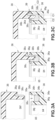
- FIG. 3(c) An enlarged view of a section 3c in Fig. 2 is illustrated in Fig. 3(c) .
- an attachment part 36a to which the cover 38 is attached is formed in the housing 36 and an annular top groove 36c to be filled with an adhesive 36b is formed in the attachment part 36a.
- the cover 38 is box-shaped and has a protrusion (referred to below as an insertion protrusion) 38a, formed along the outer periphery of the cover 38, that projects to one side.
- the cover 38 has a contacting surface 38g that comes in contact with the attachment part 36a of the housing 36 on the outer side of the insertion protrusion 38a.
- the top groove 36c includes a bottom surface 36g, an outer-side wall surface 36h that rises from one end of the bottom surface 36g on the outer side of the insertion protrusion 38a, and an inner-side wall surface 36j that rises from the other end of the bottom surface 36g on the inner side of the insertion protrusion 38a.
- an outer-side gap C1 is provided between the insertion protrusion 38a and the outer-side wall surface 36h of the top groove 36c
- an inner-side gap C2 is provided between the insertion protrusion 38a and the inner-side wall surface 36j of the top groove 36c
- a bottom-side gap C3 is provided between the insertion protrusion 38a and the bottom surface 36g of the top groove 36c.
- the inner-side gap C2 is larger than the outer-side gap C1.
- the adhesive 36b is attached to the periphery of the insertion protrusion 38a. This attachment improves the bonding performance between the insertion protrusion 38a and the adhesive 36b.
- the adhesive 36b is collected in the inner-side gap C2 and there is no concern that the adhesive 36b enters the inner side of the peripheral wall part (insertion protrusion 38a), that is, the inside of the housing 36.
- long projections 38c that come in contact with the outer-side wall surface 36h of the top groove 36c are formed on the outer side of the insertion protrusion 38a.
- the projections 38c only need to be formed in about two positions on the insertion protrusion 38a extending in the front and back direction of the drawing sheet. Even when the projections 38c are provided, the cover 38 does not become heavier.
- the insertion protrusion 38a is inserted into the top groove 36c when the cover 38 is attached to the housing 36, and the projections 38c come in contact with the outer-side wall surface 36h of the top groove 36c at this time. As a result, it is possible to prevent a rattle when the cover 38 is attached to the housing 36.
- a collecting groove 38b having a U-shaped cross section is provided in the cover 38 above the outer-side gap C1. Since the adhesive 36b is collected in this collecting groove 38b, there is no concern that the adhesive 36b protrudes to the outer side of the housing 36.
- a second collecting groove 36d is provided in the attachment part 36a so that the upper part of the outer-side gap C1 is widened upward and outward.
- the groove width of the collecting groove 38b can also be widened by providing the second collecting groove 36d.
- the second collecting groove 36d and the collecting groove 38b increase the storage amount of the excess portion of the adhesive 36b and more preferably prevent the protrusion of the adhesive 36b to the outer side of the housing 36.
- the cover 38 to be provided for the housing 36 has the insertion protrusion 38a projecting in one direction (toward the housing 36) in the outer periphery of the cover 38, the collecting groove 38b in which resin is collected in this insertion protrusion 38a, and the projections 38c extending upward and downward.
- the attachment part 36a to which the cover 38 is attached is formed in the peripheral wall part 84 that surrounds a board accommodation part 85, and the attachment part 36a is provided with the top groove 36c that is filled with the adhesive 36b and into which the insertion protrusion 38a is inserted.
- the insertion protrusion 38a is provided with the projections 38c so that the projections 38c make slidable contact with the inner surface of the top groove 36c when the cover 38 is attached.
- the cover 38 tries to move in the horizontal direction, the cover 38 cannot move in the horizontal direction since the projections 38c come in contact with the inner surface of the top groove 36c. As a result, it is possible to prevent a rattle when the cover 38 is attached to the housing 36.
- a tapered surface 38f is provided at the lower end part of the insertion protrusion 38a to form the lower end of the insertion protrusion 38a in a pointed shape. This shape enables the insertion protrusion 38a to be smoothly accommodated in the top groove 36c and to smoothly thrust the adhesive 36b.
- the insertion protrusion 38a is inserted into the top groove 36c. As illustrated in Fig. 3(b) , the adhesive 36b is pushed by the insertion protrusion 38a and partially moves to the outside of the peripheral wall part 84 or the inside of the peripheral wall part 84.
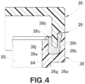
- the collecting groove 38b may be formed in the top groove 36c in the attachment part 36a of the housing 36. Since the structure other than this is the same as in Fig. 3 , reference numerals in Fig. 3 are used and detailed descriptions are omitted.
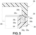
- the collecting groove 38b may be formed in the cover 38. Since the structure other than this is the same as in Fig. 3 , reference numerals in Fig. 3 are used and detailed descriptions are omitted.
- the collecting groove 38b may be provided in the housing 36, provided in the cover 38, or provided across the housing 36 and the cover 38.
- the collecting groove 38b may be provided in the top groove 36c of the attachment part 36a of the housing 36 or provided between the insertion protrusion 38a of the cover 38 and the contacting part 39.
- a projecting part 36e is formed so as to project from the housing 36 toward the cover 38.
- This projecting part 36e is provided on the attachment part 36a in which the top groove 36c for accommodating the insertion protrusion 38a of the cover 38 is formed.
- This projecting part 36e fixes (properly speaking, temporarily fixies the cover for bonding) the cover 38.
- the projecting part 36e is referred to below as the fixing part 36e.
- This fixing part 36e is a gate-shaped member extending from the attachment part 36a toward the cover 38.
- a projection 38e provided in the cover 38 is locked to a rectangular hole 36f of the fixing part 36e to fix (temporarily fix) the cover 38.
- the cover 38 has the plurality of projections 38c arranged at a predetermined pitch and these projections 38c come in contact with the outer-side wall surface 36h of the top groove 36c, so the cover 38 is attached to the housing 36 without being horizontally moved or rotated.
- the projections 38c are provided on the outer surface of the cover 38 in the embodiment, but the projections 38c may be provided on the inner surface of the cover 38. In this case, the projections 38c come in contact with the inner-side wall surface 36j of the top groove 36c.
- FIG. 7(b) An enlarged view of a section 7b in Fig. 2 is illustrated in Fig. 7(b) and an exploded view of Fig. 7(b) is illustrated in Fig. 7(a) .
- the peripheral wall part 84 of the housing 36 has a flange 92 that comes in contact with the base body 40, and the flange 92 overhangs toward the outer side from the peripheral wall part 84 and has a lower groove 92b for collecting an adhesive 92a in a surface close to the base body 40.
- a bottom surface 92c of the lower groove 92b is a coarse surface 92d.
- the housing 36 is brought in contact with the base body 40 so that the adhesive 92a is accommodated in the lower groove 92b.
- the surface of the flange 92 close to the base body 40 is divided by the lower groove 92b into an outer-side surface 92e and an inner-side surface 92f in Fig. 7(b) and a small gap 92g is provided between the inner-side surface 92f and the base body 40.
- openings are provided on the front side and the back side of the housing 36 in the embodiment, but one of these sides may be closed. That is, the housing 36 only needs to have an opening at least one side.
- the resinous component 36 according to the invention may be applied to any device or apparatus in addition to the vehicle brake fluid pressure control device 10 and the use thereof is not limited to the embodiment.
- the resinous component 36 is more suitable for the vehicle brake fluid pressure control device 10 that particularly requires drip-proof performance.
- the resinous component according to the invention is preferably applied to a vehicle brake fluid pressure control device.
Landscapes
- Engineering & Computer Science (AREA)
- Mechanical Engineering (AREA)
- Architecture (AREA)
- Civil Engineering (AREA)
- Structural Engineering (AREA)
- General Engineering & Computer Science (AREA)
- Physics & Mathematics (AREA)
- Transportation (AREA)
- Fluid Mechanics (AREA)
- Regulating Braking Force (AREA)
- Connection Of Plates (AREA)
- Standing Axle, Rod, Or Tube Structures Coupled By Welding, Adhesion, Or Deposition (AREA)
- Casings For Electric Apparatus (AREA)
- Lining Or Joining Of Plastics Or The Like (AREA)
- Organic Insulating Materials (AREA)
- Developing Agents For Electrophotography (AREA)
- Transition And Organic Metals Composition Catalysts For Addition Polymerization (AREA)
Claims (3)
- Composant résineux comprenant :un logement en forme de boîte (36) ayant une ouverture ; etun couvercle (38) fixé à l'ouverture du logement (36),l'ouverture du logement (36) a une rainure supérieure (36c) destinée à être remplie par un adhésif (36b),la rainure supérieure (36c) comprend une surface inférieure (36g), une surface de paroi côté externe (36h) qui s'élève depuis une extrémité de la surface inférieure (36g) et une surface de paroi côté interne (36j) qui s'élève depuis l'autre extrémité de la surface inférieure (36g),le couvercle (38) a une protubérance d'insertion (38a) destinée à être insérée dans la rainure supérieure (36c),un espace côté inférieur (C3) est ménagé entre la protubérance d'insertion (38a) et la surface inférieure (36g), un espace côté externe (C1) est ménagé entre la protubérance d'insertion (38a) et la surface de paroi côté externe (36h), et un espace côté interne (C2) est ménagé entre la protubérance d'insertion (38a) et la surface de paroi côté interne (36j),l'espace côté interne (C2) est plus grand que l'espace côté externe (C1), etdans lequel le logement (36) a une partie de paroi périphérique (84) et une partie de réception de carte (85) dans laquelle une carte de commande (99) est reçue, caractérisé en ce quela partie de paroi périphérique (84) a une bride (92) qui vient en contact avec un corps de base (40),la bride (92) surplombe vers un côté externe de la partie de paroi périphérique (84) et a, dans un côté proche du corps de base (40), une rainure inférieure (92b) destiné à être remplie d'un adhésif (92a), etune surface périphérique interne de la rainure inférieure (92b) est une surface rugueuse.
- Composant résineux selon la revendication 1,
dans lequel la protubérance d'insertion (38a) comprend en outre une saillie (38c) qui vient en contact avec la surface de paroi côté externe (36h). - Composant résineux selon la revendication 1 ou 2,dans lequel une surface de la bride (92) proche du corps de base (40) est divisée par la rainure inférieure (92b) en une surface côté externe (92e) sur un côté externe de la rainure inférieure (92b) et une surface côté interne (92f) sur un côté interne de la rainure inférieure (92b) etun espace (92g) est prévu entre la surface côté interne (92f) et le corps de base (40).
Applications Claiming Priority (2)
| Application Number | Priority Date | Filing Date | Title |
|---|---|---|---|
| JP2017028511 | 2017-02-17 | ||
| PCT/JP2018/004783 WO2018151064A1 (fr) | 2017-02-17 | 2018-02-13 | Composant résineux |
Publications (3)
| Publication Number | Publication Date |
|---|---|
| EP3584452A1 EP3584452A1 (fr) | 2019-12-25 |
| EP3584452A4 EP3584452A4 (fr) | 2020-12-09 |
| EP3584452B1 true EP3584452B1 (fr) | 2023-06-07 |
Family
ID=63170203
Family Applications (1)
| Application Number | Title | Priority Date | Filing Date |
|---|---|---|---|
| EP18753644.6A Active EP3584452B1 (fr) | 2017-02-17 | 2018-02-13 | Composant résineux |
Country Status (6)
| Country | Link |
|---|---|
| EP (1) | EP3584452B1 (fr) |
| JP (1) | JP6873367B2 (fr) |
| CN (1) | CN110114585B (fr) |
| ES (1) | ES2948764T3 (fr) |
| TW (1) | TWI751288B (fr) |
| WO (1) | WO2018151064A1 (fr) |
Families Citing this family (5)
| Publication number | Priority date | Publication date | Assignee | Title |
|---|---|---|---|---|
| CN109751415A (zh) * | 2018-12-25 | 2019-05-14 | 北京品驰医疗设备有限公司 | 密封元件 |
| JP2020167761A (ja) * | 2019-03-28 | 2020-10-08 | 日本電産株式会社 | モータ |
| JP2020188653A (ja) * | 2019-05-17 | 2020-11-19 | 株式会社デンソー | 駆動装置 |
| EP4429081A4 (fr) * | 2021-11-05 | 2025-02-19 | Mitsubishi Electric Corporation | Machine électrique rotative |
| CN118391333B (zh) * | 2024-06-20 | 2024-09-03 | 江西省科技基础条件平台中心(江西省计算中心) | 粘接固定结构、高精密传感器及其粘接安装方法 |
Family Cites Families (12)
| Publication number | Priority date | Publication date | Assignee | Title |
|---|---|---|---|---|
| DE2908539A1 (de) * | 1979-03-05 | 1980-09-18 | Franz Dwuzet | Verfahren zum befestigen von fassadenverkleidungen sowie befestigungselement fuer fassadenverkleidungen |
| JPS591725B2 (ja) | 1979-10-04 | 1984-01-13 | 株式会社トクヤマ | 陽イオン交換樹脂の製造方法 |
| JP2594813Y2 (ja) * | 1991-09-13 | 1999-05-10 | 旭光学工業株式会社 | 接着部材 |
| US6021753A (en) * | 1996-07-03 | 2000-02-08 | Ford Global Technologies, Inc. | Adhesively bonded plastic automotive air intake assembly |
| US6456497B1 (en) * | 1998-03-12 | 2002-09-24 | Itt Manufacturing Enterprises, Inc. | Night vision binoculars |
| JP2004069564A (ja) * | 2002-08-07 | 2004-03-04 | Denso Corp | 接着構造 |
| JP4520915B2 (ja) | 2005-07-13 | 2010-08-11 | 日信工業株式会社 | 車両用ブレーキ液圧制御装置 |
| JP4892527B2 (ja) | 2008-08-29 | 2012-03-07 | 日立オートモティブシステムズ株式会社 | 電子制御装置 |
| JP5829110B2 (ja) * | 2011-11-29 | 2015-12-09 | 日立オートモティブシステムズ株式会社 | 電子モジュール |
| JP2014061629A (ja) * | 2012-09-20 | 2014-04-10 | Yachihoko Kagaku Kk | ラインストーン付き装飾体、及びその製造方法 |
| JP6058350B2 (ja) * | 2012-10-25 | 2017-01-11 | 京セラ株式会社 | 電子部品を内蔵する筐体の防水構造 |
| JP6192324B2 (ja) | 2013-03-21 | 2017-09-06 | 日立オートモティブシステムズ株式会社 | 電子制御装置 |
-
2018
- 2018-02-13 EP EP18753644.6A patent/EP3584452B1/fr active Active
- 2018-02-13 ES ES18753644T patent/ES2948764T3/es active Active
- 2018-02-13 CN CN201880005428.1A patent/CN110114585B/zh active Active
- 2018-02-13 WO PCT/JP2018/004783 patent/WO2018151064A1/fr not_active Ceased
- 2018-02-13 JP JP2018568508A patent/JP6873367B2/ja active Active
- 2018-02-14 TW TW107105633A patent/TWI751288B/zh active
Also Published As
| Publication number | Publication date |
|---|---|
| CN110114585A (zh) | 2019-08-09 |
| ES2948764T3 (es) | 2023-09-18 |
| WO2018151064A1 (fr) | 2018-08-23 |
| CN110114585B (zh) | 2021-09-17 |
| EP3584452A1 (fr) | 2019-12-25 |
| TW201836886A (zh) | 2018-10-16 |
| JP6873367B2 (ja) | 2021-05-19 |
| JPWO2018151064A1 (ja) | 2019-11-07 |
| EP3584452A4 (fr) | 2020-12-09 |
| TWI751288B (zh) | 2022-01-01 |
Similar Documents
| Publication | Publication Date | Title |
|---|---|---|
| EP3584452B1 (fr) | Composant résineux | |
| US8408945B2 (en) | Electronic device having a can housing and method for producing the same | |
| US9190766B2 (en) | Electronic control apparatus for vehicle using water proof type housing sealing and method thereof | |
| US6799812B2 (en) | Integrated pressure sensor module | |
| KR101407154B1 (ko) | 차량의 전자제어장치 | |
| CN102986315B (zh) | 用于汽车的适合与插头触点接通的电气组件 | |
| US20140362533A1 (en) | Electronic control apparatus for vehicle | |
| EP3584130A1 (fr) | Dispositif de commande de pression de liquide de frein de véhicule | |
| EP3584810B9 (fr) | Ensemble bobine et dispositif de commande de frein | |
| JP6639965B2 (ja) | 電子制御装置 | |
| JP2014184744A (ja) | 電子制御装置 | |
| US10021799B2 (en) | Electronic control apparatus for vehicle using potting layer and method of manufacturing the same | |
| JP2014061755A (ja) | 液圧制御装置 | |
| CN104859614B (zh) | 用于制动流体压力控制的致动器 | |
| JP2000168530A (ja) | 車両用ブレーキ液圧制御装置 | |
| JP2013035320A (ja) | 電子制御装置 | |
| JP3600302B2 (ja) | コネクタ端子ユニットと配線基板との接続構造およびその組付方法 | |
| KR101268472B1 (ko) | 모듈레이터 블록 |
Legal Events
| Date | Code | Title | Description |
|---|---|---|---|
| STAA | Information on the status of an ep patent application or granted ep patent |
Free format text: STATUS: THE INTERNATIONAL PUBLICATION HAS BEEN MADE |
|
| PUAI | Public reference made under article 153(3) epc to a published international application that has entered the european phase |
Free format text: ORIGINAL CODE: 0009012 |
|
| STAA | Information on the status of an ep patent application or granted ep patent |
Free format text: STATUS: REQUEST FOR EXAMINATION WAS MADE |
|
| 17P | Request for examination filed |
Effective date: 20190606 |
|
| AK | Designated contracting states |
Kind code of ref document: A1 Designated state(s): AL AT BE BG CH CY CZ DE DK EE ES FI FR GB GR HR HU IE IS IT LI LT LU LV MC MK MT NL NO PL PT RO RS SE SI SK SM TR |
|
| AX | Request for extension of the european patent |
Extension state: BA ME |
|
| DAV | Request for validation of the european patent (deleted) | ||
| DAX | Request for extension of the european patent (deleted) | ||
| A4 | Supplementary search report drawn up and despatched |
Effective date: 20201111 |
|
| RIC1 | Information provided on ipc code assigned before grant |
Ipc: H02G 3/14 20060101ALI20201105BHEP Ipc: B60R 16/02 20060101ALI20201105BHEP Ipc: H05K 5/06 20060101ALI20201105BHEP Ipc: B29C 65/00 20060101ALI20201105BHEP Ipc: B60T 8/34 20060101ALI20201105BHEP Ipc: B29C 65/48 20060101ALI20201105BHEP Ipc: F16B 11/00 20060101AFI20201105BHEP Ipc: H02G 3/16 20060101ALI20201105BHEP |
|
| RAP1 | Party data changed (applicant data changed or rights of an application transferred) |
Owner name: HITACHI ASTEMO, LTD. |
|
| GRAP | Despatch of communication of intention to grant a patent |
Free format text: ORIGINAL CODE: EPIDOSNIGR1 |
|
| STAA | Information on the status of an ep patent application or granted ep patent |
Free format text: STATUS: GRANT OF PATENT IS INTENDED |
|
| INTG | Intention to grant announced |
Effective date: 20221223 |
|
| GRAS | Grant fee paid |
Free format text: ORIGINAL CODE: EPIDOSNIGR3 |
|
| GRAA | (expected) grant |
Free format text: ORIGINAL CODE: 0009210 |
|
| STAA | Information on the status of an ep patent application or granted ep patent |
Free format text: STATUS: THE PATENT HAS BEEN GRANTED |
|
| AK | Designated contracting states |
Kind code of ref document: B1 Designated state(s): AL AT BE BG CH CY CZ DE DK EE ES FI FR GB GR HR HU IE IS IT LI LT LU LV MC MK MT NL NO PL PT RO RS SE SI SK SM TR |
|
| REG | Reference to a national code |
Ref country code: GB Ref legal event code: FG4D |
|
| REG | Reference to a national code |
Ref country code: CH Ref legal event code: EP Ref country code: AT Ref legal event code: REF Ref document number: 1575888 Country of ref document: AT Kind code of ref document: T Effective date: 20230615 |
|
| REG | Reference to a national code |
Ref country code: DE Ref legal event code: R096 Ref document number: 602018051118 Country of ref document: DE |
|
| REG | Reference to a national code |
Ref country code: ES Ref legal event code: FG2A Ref document number: 2948764 Country of ref document: ES Kind code of ref document: T3 Effective date: 20230918 |
|
| REG | Reference to a national code |
Ref country code: LT Ref legal event code: MG9D |
|
| REG | Reference to a national code |
Ref country code: NL Ref legal event code: MP Effective date: 20230607 |
|
| PG25 | Lapsed in a contracting state [announced via postgrant information from national office to epo] |
Ref country code: SE Free format text: LAPSE BECAUSE OF FAILURE TO SUBMIT A TRANSLATION OF THE DESCRIPTION OR TO PAY THE FEE WITHIN THE PRESCRIBED TIME-LIMIT Effective date: 20230607 Ref country code: NO Free format text: LAPSE BECAUSE OF FAILURE TO SUBMIT A TRANSLATION OF THE DESCRIPTION OR TO PAY THE FEE WITHIN THE PRESCRIBED TIME-LIMIT Effective date: 20230907 |
|
| REG | Reference to a national code |
Ref country code: AT Ref legal event code: MK05 Ref document number: 1575888 Country of ref document: AT Kind code of ref document: T Effective date: 20230607 |
|
| PG25 | Lapsed in a contracting state [announced via postgrant information from national office to epo] |
Ref country code: RS Free format text: LAPSE BECAUSE OF FAILURE TO SUBMIT A TRANSLATION OF THE DESCRIPTION OR TO PAY THE FEE WITHIN THE PRESCRIBED TIME-LIMIT Effective date: 20230607 Ref country code: NL Free format text: LAPSE BECAUSE OF FAILURE TO SUBMIT A TRANSLATION OF THE DESCRIPTION OR TO PAY THE FEE WITHIN THE PRESCRIBED TIME-LIMIT Effective date: 20230607 Ref country code: LV Free format text: LAPSE BECAUSE OF FAILURE TO SUBMIT A TRANSLATION OF THE DESCRIPTION OR TO PAY THE FEE WITHIN THE PRESCRIBED TIME-LIMIT Effective date: 20230607 Ref country code: LT Free format text: LAPSE BECAUSE OF FAILURE TO SUBMIT A TRANSLATION OF THE DESCRIPTION OR TO PAY THE FEE WITHIN THE PRESCRIBED TIME-LIMIT Effective date: 20230607 Ref country code: HR Free format text: LAPSE BECAUSE OF FAILURE TO SUBMIT A TRANSLATION OF THE DESCRIPTION OR TO PAY THE FEE WITHIN THE PRESCRIBED TIME-LIMIT Effective date: 20230607 Ref country code: GR Free format text: LAPSE BECAUSE OF FAILURE TO SUBMIT A TRANSLATION OF THE DESCRIPTION OR TO PAY THE FEE WITHIN THE PRESCRIBED TIME-LIMIT Effective date: 20230908 |
|
| PG25 | Lapsed in a contracting state [announced via postgrant information from national office to epo] |
Ref country code: FI Free format text: LAPSE BECAUSE OF FAILURE TO SUBMIT A TRANSLATION OF THE DESCRIPTION OR TO PAY THE FEE WITHIN THE PRESCRIBED TIME-LIMIT Effective date: 20230607 |
|
| PG25 | Lapsed in a contracting state [announced via postgrant information from national office to epo] |
Ref country code: SK Free format text: LAPSE BECAUSE OF FAILURE TO SUBMIT A TRANSLATION OF THE DESCRIPTION OR TO PAY THE FEE WITHIN THE PRESCRIBED TIME-LIMIT Effective date: 20230607 |
|
| PG25 | Lapsed in a contracting state [announced via postgrant information from national office to epo] |
Ref country code: IS Free format text: LAPSE BECAUSE OF FAILURE TO SUBMIT A TRANSLATION OF THE DESCRIPTION OR TO PAY THE FEE WITHIN THE PRESCRIBED TIME-LIMIT Effective date: 20231007 |
|
| PG25 | Lapsed in a contracting state [announced via postgrant information from national office to epo] |
Ref country code: SM Free format text: LAPSE BECAUSE OF FAILURE TO SUBMIT A TRANSLATION OF THE DESCRIPTION OR TO PAY THE FEE WITHIN THE PRESCRIBED TIME-LIMIT Effective date: 20230607 Ref country code: SK Free format text: LAPSE BECAUSE OF FAILURE TO SUBMIT A TRANSLATION OF THE DESCRIPTION OR TO PAY THE FEE WITHIN THE PRESCRIBED TIME-LIMIT Effective date: 20230607 Ref country code: RO Free format text: LAPSE BECAUSE OF FAILURE TO SUBMIT A TRANSLATION OF THE DESCRIPTION OR TO PAY THE FEE WITHIN THE PRESCRIBED TIME-LIMIT Effective date: 20230607 Ref country code: PT Free format text: LAPSE BECAUSE OF FAILURE TO SUBMIT A TRANSLATION OF THE DESCRIPTION OR TO PAY THE FEE WITHIN THE PRESCRIBED TIME-LIMIT Effective date: 20231009 Ref country code: IS Free format text: LAPSE BECAUSE OF FAILURE TO SUBMIT A TRANSLATION OF THE DESCRIPTION OR TO PAY THE FEE WITHIN THE PRESCRIBED TIME-LIMIT Effective date: 20231007 Ref country code: EE Free format text: LAPSE BECAUSE OF FAILURE TO SUBMIT A TRANSLATION OF THE DESCRIPTION OR TO PAY THE FEE WITHIN THE PRESCRIBED TIME-LIMIT Effective date: 20230607 Ref country code: CZ Free format text: LAPSE BECAUSE OF FAILURE TO SUBMIT A TRANSLATION OF THE DESCRIPTION OR TO PAY THE FEE WITHIN THE PRESCRIBED TIME-LIMIT Effective date: 20230607 Ref country code: AT Free format text: LAPSE BECAUSE OF FAILURE TO SUBMIT A TRANSLATION OF THE DESCRIPTION OR TO PAY THE FEE WITHIN THE PRESCRIBED TIME-LIMIT Effective date: 20230607 |
|
| PG25 | Lapsed in a contracting state [announced via postgrant information from national office to epo] |
Ref country code: PL Free format text: LAPSE BECAUSE OF FAILURE TO SUBMIT A TRANSLATION OF THE DESCRIPTION OR TO PAY THE FEE WITHIN THE PRESCRIBED TIME-LIMIT Effective date: 20230607 |
|
| REG | Reference to a national code |
Ref country code: DE Ref legal event code: R097 Ref document number: 602018051118 Country of ref document: DE |
|
| PLBE | No opposition filed within time limit |
Free format text: ORIGINAL CODE: 0009261 |
|
| STAA | Information on the status of an ep patent application or granted ep patent |
Free format text: STATUS: NO OPPOSITION FILED WITHIN TIME LIMIT |
|
| PG25 | Lapsed in a contracting state [announced via postgrant information from national office to epo] |
Ref country code: DK Free format text: LAPSE BECAUSE OF FAILURE TO SUBMIT A TRANSLATION OF THE DESCRIPTION OR TO PAY THE FEE WITHIN THE PRESCRIBED TIME-LIMIT Effective date: 20230607 |
|
| PG25 | Lapsed in a contracting state [announced via postgrant information from national office to epo] |
Ref country code: SI Free format text: LAPSE BECAUSE OF FAILURE TO SUBMIT A TRANSLATION OF THE DESCRIPTION OR TO PAY THE FEE WITHIN THE PRESCRIBED TIME-LIMIT Effective date: 20230607 |
|
| 26N | No opposition filed |
Effective date: 20240308 |
|
| PG25 | Lapsed in a contracting state [announced via postgrant information from national office to epo] |
Ref country code: SI Free format text: LAPSE BECAUSE OF FAILURE TO SUBMIT A TRANSLATION OF THE DESCRIPTION OR TO PAY THE FEE WITHIN THE PRESCRIBED TIME-LIMIT Effective date: 20230607 |
|
| PG25 | Lapsed in a contracting state [announced via postgrant information from national office to epo] |
Ref country code: MC Free format text: LAPSE BECAUSE OF FAILURE TO SUBMIT A TRANSLATION OF THE DESCRIPTION OR TO PAY THE FEE WITHIN THE PRESCRIBED TIME-LIMIT Effective date: 20230607 |
|
| REG | Reference to a national code |
Ref country code: CH Ref legal event code: PL |
|
| PG25 | Lapsed in a contracting state [announced via postgrant information from national office to epo] |
Ref country code: LU Free format text: LAPSE BECAUSE OF NON-PAYMENT OF DUE FEES Effective date: 20240213 |
|
| PG25 | Lapsed in a contracting state [announced via postgrant information from national office to epo] |
Ref country code: CH Free format text: LAPSE BECAUSE OF NON-PAYMENT OF DUE FEES Effective date: 20240229 |
|
| PG25 | Lapsed in a contracting state [announced via postgrant information from national office to epo] |
Ref country code: LU Free format text: LAPSE BECAUSE OF NON-PAYMENT OF DUE FEES Effective date: 20240213 Ref country code: CH Free format text: LAPSE BECAUSE OF NON-PAYMENT OF DUE FEES Effective date: 20240229 |
|
| PG25 | Lapsed in a contracting state [announced via postgrant information from national office to epo] |
Ref country code: BG Free format text: LAPSE BECAUSE OF FAILURE TO SUBMIT A TRANSLATION OF THE DESCRIPTION OR TO PAY THE FEE WITHIN THE PRESCRIBED TIME-LIMIT Effective date: 20230607 |
|
| PG25 | Lapsed in a contracting state [announced via postgrant information from national office to epo] |
Ref country code: BG Free format text: LAPSE BECAUSE OF FAILURE TO SUBMIT A TRANSLATION OF THE DESCRIPTION OR TO PAY THE FEE WITHIN THE PRESCRIBED TIME-LIMIT Effective date: 20230607 |
|
| REG | Reference to a national code |
Ref country code: BE Ref legal event code: MM Effective date: 20240229 |
|
| PG25 | Lapsed in a contracting state [announced via postgrant information from national office to epo] |
Ref country code: BE Free format text: LAPSE BECAUSE OF NON-PAYMENT OF DUE FEES Effective date: 20240229 |
|
| PG25 | Lapsed in a contracting state [announced via postgrant information from national office to epo] |
Ref country code: FR Free format text: LAPSE BECAUSE OF NON-PAYMENT OF DUE FEES Effective date: 20240229 |
|
| PG25 | Lapsed in a contracting state [announced via postgrant information from national office to epo] |
Ref country code: IE Free format text: LAPSE BECAUSE OF NON-PAYMENT OF DUE FEES Effective date: 20240213 |
|
| PG25 | Lapsed in a contracting state [announced via postgrant information from national office to epo] |
Ref country code: IE Free format text: LAPSE BECAUSE OF NON-PAYMENT OF DUE FEES Effective date: 20240213 Ref country code: FR Free format text: LAPSE BECAUSE OF NON-PAYMENT OF DUE FEES Effective date: 20240229 Ref country code: BE Free format text: LAPSE BECAUSE OF NON-PAYMENT OF DUE FEES Effective date: 20240229 |
|
| PG25 | Lapsed in a contracting state [announced via postgrant information from national office to epo] |
Ref country code: CY Free format text: LAPSE BECAUSE OF FAILURE TO SUBMIT A TRANSLATION OF THE DESCRIPTION OR TO PAY THE FEE WITHIN THE PRESCRIBED TIME-LIMIT; INVALID AB INITIO Effective date: 20180213 |
|
| PG25 | Lapsed in a contracting state [announced via postgrant information from national office to epo] |
Ref country code: HU Free format text: LAPSE BECAUSE OF FAILURE TO SUBMIT A TRANSLATION OF THE DESCRIPTION OR TO PAY THE FEE WITHIN THE PRESCRIBED TIME-LIMIT; INVALID AB INITIO Effective date: 20180213 |
|
| PG25 | Lapsed in a contracting state [announced via postgrant information from national office to epo] |
Ref country code: TR Free format text: LAPSE BECAUSE OF FAILURE TO SUBMIT A TRANSLATION OF THE DESCRIPTION OR TO PAY THE FEE WITHIN THE PRESCRIBED TIME-LIMIT Effective date: 20230607 |
|
| PGFP | Annual fee paid to national office [announced via postgrant information from national office to epo] |
Ref country code: GB Payment date: 20260106 Year of fee payment: 9 |
|
| PGFP | Annual fee paid to national office [announced via postgrant information from national office to epo] |
Ref country code: ES Payment date: 20260304 Year of fee payment: 9 |
|
| PGFP | Annual fee paid to national office [announced via postgrant information from national office to epo] |
Ref country code: DE Payment date: 20251230 Year of fee payment: 9 |
|
| PGFP | Annual fee paid to national office [announced via postgrant information from national office to epo] |
Ref country code: IT Payment date: 20260122 Year of fee payment: 9 |