EP3584497A1 - Fahrzeugleuchte und fahrzeuglampenvorrichtung - Google Patents
Fahrzeugleuchte und fahrzeuglampenvorrichtung Download PDFInfo
- Publication number
- EP3584497A1 EP3584497A1 EP19152957.7A EP19152957A EP3584497A1 EP 3584497 A1 EP3584497 A1 EP 3584497A1 EP 19152957 A EP19152957 A EP 19152957A EP 3584497 A1 EP3584497 A1 EP 3584497A1
- Authority
- EP
- European Patent Office
- Prior art keywords
- light
- board
- emitting element
- control element
- control unit
- Prior art date
- Legal status (The legal status is an assumption and is not a legal conclusion. Google has not performed a legal analysis and makes no representation as to the accuracy of the status listed.)
- Granted
Links
Images


Classifications
-
- F—MECHANICAL ENGINEERING; LIGHTING; HEATING; WEAPONS; BLASTING
- F21—LIGHTING
- F21S—NON-PORTABLE LIGHTING DEVICES; SYSTEMS THEREOF; VEHICLE LIGHTING DEVICES SPECIALLY ADAPTED FOR VEHICLE EXTERIORS
- F21S43/00—Signalling devices specially adapted for vehicle exteriors, e.g. brake lamps, direction indicator lights or reversing lights
- F21S43/10—Signalling devices specially adapted for vehicle exteriors, e.g. brake lamps, direction indicator lights or reversing lights characterised by the light source
- F21S43/13—Signalling devices specially adapted for vehicle exteriors, e.g. brake lamps, direction indicator lights or reversing lights characterised by the light source characterised by the type of light source
- F21S43/14—Light emitting diodes [LED]
-
- F—MECHANICAL ENGINEERING; LIGHTING; HEATING; WEAPONS; BLASTING
- F21—LIGHTING
- F21S—NON-PORTABLE LIGHTING DEVICES; SYSTEMS THEREOF; VEHICLE LIGHTING DEVICES SPECIALLY ADAPTED FOR VEHICLE EXTERIORS
- F21S41/00—Illuminating devices specially adapted for vehicle exteriors, e.g. headlamps
- F21S41/10—Illuminating devices specially adapted for vehicle exteriors, e.g. headlamps characterised by the light source
- F21S41/14—Illuminating devices specially adapted for vehicle exteriors, e.g. headlamps characterised by the light source characterised by the type of light source
- F21S41/141—Light emitting diodes [LED]
- F21S41/143—Light emitting diodes [LED] the main emission direction of the LED being parallel to the optical axis of the illuminating device
-
- F—MECHANICAL ENGINEERING; LIGHTING; HEATING; WEAPONS; BLASTING
- F21—LIGHTING
- F21S—NON-PORTABLE LIGHTING DEVICES; SYSTEMS THEREOF; VEHICLE LIGHTING DEVICES SPECIALLY ADAPTED FOR VEHICLE EXTERIORS
- F21S41/00—Illuminating devices specially adapted for vehicle exteriors, e.g. headlamps
- F21S41/10—Illuminating devices specially adapted for vehicle exteriors, e.g. headlamps characterised by the light source
- F21S41/19—Attachment of light sources or lamp holders
-
- F—MECHANICAL ENGINEERING; LIGHTING; HEATING; WEAPONS; BLASTING
- F21—LIGHTING
- F21S—NON-PORTABLE LIGHTING DEVICES; SYSTEMS THEREOF; VEHICLE LIGHTING DEVICES SPECIALLY ADAPTED FOR VEHICLE EXTERIORS
- F21S41/00—Illuminating devices specially adapted for vehicle exteriors, e.g. headlamps
- F21S41/10—Illuminating devices specially adapted for vehicle exteriors, e.g. headlamps characterised by the light source
- F21S41/19—Attachment of light sources or lamp holders
- F21S41/192—Details of lamp holders, terminals or connectors
-
- F—MECHANICAL ENGINEERING; LIGHTING; HEATING; WEAPONS; BLASTING
- F21—LIGHTING
- F21S—NON-PORTABLE LIGHTING DEVICES; SYSTEMS THEREOF; VEHICLE LIGHTING DEVICES SPECIALLY ADAPTED FOR VEHICLE EXTERIORS
- F21S41/00—Illuminating devices specially adapted for vehicle exteriors, e.g. headlamps
- F21S41/10—Illuminating devices specially adapted for vehicle exteriors, e.g. headlamps characterised by the light source
- F21S41/19—Attachment of light sources or lamp holders
- F21S41/194—Bayonet attachments
-
- F—MECHANICAL ENGINEERING; LIGHTING; HEATING; WEAPONS; BLASTING
- F21—LIGHTING
- F21S—NON-PORTABLE LIGHTING DEVICES; SYSTEMS THEREOF; VEHICLE LIGHTING DEVICES SPECIALLY ADAPTED FOR VEHICLE EXTERIORS
- F21S43/00—Signalling devices specially adapted for vehicle exteriors, e.g. brake lamps, direction indicator lights or reversing lights
- F21S43/10—Signalling devices specially adapted for vehicle exteriors, e.g. brake lamps, direction indicator lights or reversing lights characterised by the light source
- F21S43/19—Attachment of light sources or lamp holders
-
- F—MECHANICAL ENGINEERING; LIGHTING; HEATING; WEAPONS; BLASTING
- F21—LIGHTING
- F21S—NON-PORTABLE LIGHTING DEVICES; SYSTEMS THEREOF; VEHICLE LIGHTING DEVICES SPECIALLY ADAPTED FOR VEHICLE EXTERIORS
- F21S43/00—Signalling devices specially adapted for vehicle exteriors, e.g. brake lamps, direction indicator lights or reversing lights
- F21S43/10—Signalling devices specially adapted for vehicle exteriors, e.g. brake lamps, direction indicator lights or reversing lights characterised by the light source
- F21S43/19—Attachment of light sources or lamp holders
- F21S43/195—Details of lamp holders, terminals or connectors
-
- F—MECHANICAL ENGINEERING; LIGHTING; HEATING; WEAPONS; BLASTING
- F21—LIGHTING
- F21S—NON-PORTABLE LIGHTING DEVICES; SYSTEMS THEREOF; VEHICLE LIGHTING DEVICES SPECIALLY ADAPTED FOR VEHICLE EXTERIORS
- F21S45/00—Arrangements within vehicle lighting devices specially adapted for vehicle exteriors, for purposes other than emission or distribution of light
- F21S45/10—Protection of lighting devices
-
- F—MECHANICAL ENGINEERING; LIGHTING; HEATING; WEAPONS; BLASTING
- F21—LIGHTING
- F21S—NON-PORTABLE LIGHTING DEVICES; SYSTEMS THEREOF; VEHICLE LIGHTING DEVICES SPECIALLY ADAPTED FOR VEHICLE EXTERIORS
- F21S45/00—Arrangements within vehicle lighting devices specially adapted for vehicle exteriors, for purposes other than emission or distribution of light
- F21S45/40—Cooling of lighting devices
- F21S45/47—Passive cooling, e.g. using fins, thermal conductive elements or openings
-
- F—MECHANICAL ENGINEERING; LIGHTING; HEATING; WEAPONS; BLASTING
- F21—LIGHTING
- F21V—FUNCTIONAL FEATURES OR DETAILS OF LIGHTING DEVICES OR SYSTEMS THEREOF; STRUCTURAL COMBINATIONS OF LIGHTING DEVICES WITH OTHER ARTICLES, NOT OTHERWISE PROVIDED FOR
- F21V23/00—Arrangement of electric circuit elements in or on lighting devices
- F21V23/003—Arrangement of electric circuit elements in or on lighting devices the elements being electronics drivers or controllers for operating the light source, e.g. for a LED array
- F21V23/004—Arrangement of electric circuit elements in or on lighting devices the elements being electronics drivers or controllers for operating the light source, e.g. for a LED array arranged on a substrate, e.g. a printed circuit board
- F21V23/005—Arrangement of electric circuit elements in or on lighting devices the elements being electronics drivers or controllers for operating the light source, e.g. for a LED array arranged on a substrate, e.g. a printed circuit board the substrate is supporting also the light source
-
- F—MECHANICAL ENGINEERING; LIGHTING; HEATING; WEAPONS; BLASTING
- F21—LIGHTING
- F21V—FUNCTIONAL FEATURES OR DETAILS OF LIGHTING DEVICES OR SYSTEMS THEREOF; STRUCTURAL COMBINATIONS OF LIGHTING DEVICES WITH OTHER ARTICLES, NOT OTHERWISE PROVIDED FOR
- F21V25/00—Safety devices structurally associated with lighting devices
- F21V25/10—Safety devices structurally associated with lighting devices coming into action when lighting device is overloaded, e.g. thermal switch
-
- F—MECHANICAL ENGINEERING; LIGHTING; HEATING; WEAPONS; BLASTING
- F21—LIGHTING
- F21V—FUNCTIONAL FEATURES OR DETAILS OF LIGHTING DEVICES OR SYSTEMS THEREOF; STRUCTURAL COMBINATIONS OF LIGHTING DEVICES WITH OTHER ARTICLES, NOT OTHERWISE PROVIDED FOR
- F21V29/00—Protecting lighting devices from thermal damage; Cooling or heating arrangements specially adapted for lighting devices or systems
- F21V29/50—Cooling arrangements
- F21V29/70—Cooling arrangements characterised by passive heat-dissipating elements, e.g. heat-sinks
- F21V29/83—Cooling arrangements characterised by passive heat-dissipating elements, e.g. heat-sinks the elements having apertures, ducts or channels, e.g. heat radiation holes
-
- H—ELECTRICITY
- H05—ELECTRIC TECHNIQUES NOT OTHERWISE PROVIDED FOR
- H05B—ELECTRIC HEATING; ELECTRIC LIGHT SOURCES NOT OTHERWISE PROVIDED FOR; CIRCUIT ARRANGEMENTS FOR ELECTRIC LIGHT SOURCES, IN GENERAL
- H05B45/00—Circuit arrangements for operating light-emitting diodes [LED]
- H05B45/50—Circuit arrangements for operating light-emitting diodes [LED] responsive to malfunctions or undesirable behaviour of LEDs; responsive to LED life; Protective circuits
- H05B45/56—Circuit arrangements for operating light-emitting diodes [LED] responsive to malfunctions or undesirable behaviour of LEDs; responsive to LED life; Protective circuits involving measures to prevent abnormal temperature of the LEDs
Definitions
- Embodiments described herein relate generally to a vehicle luminaire and a vehicle lamp device.
- the vehicle luminaire having a socket and a light-emitting module provided in one end side of the socket.
- the light-emitting module has a board provided with a wiring pattern and a light-emitting diode (LED) electrically connected to the wiring pattern.
- LED light-emitting diode
- a voltage is applied to the vehicle luminaire (light-emitting module).
- a voltage is applied to the light-emitting module, a current flows to the light-emitting diode, so that heat is generated, and a temperature of the light-emitting diode increases.
- the voltage applied to the vehicle luminaire fluctuates. For this reason, an overvoltage significantly increases the temperature of the light-emitting diode, so that a failure may occur in the light-emitting diode, or a service life of the light-emitting diode may be reduced.
- a technique in which a circuit obtained by connecting a resistance and a thermistor (positive temperature coefficient thermistor) in series and a resistance are connected in parallel, so that the thermistor cuts off the current in the event of an overvoltage to allow the current to flow only to the resistance connected in parallel.
- a value of the resistance connected in series to the light-emitting diode increases. Therefore, it is possible to suppress the temperature of the light-emitting diode from excessively increasing.
- the temperature of the thermistor changes. For this reason, it is necessary to select a thermistor having a suitable Curie point and a suitable resistance value depending on the specification, size, use purpose, or the like of the vehicle luminaire.
- the thermistor is selected depending on the specification of the vehicle luminaire or the like, it is necessary to stock a plurality of types of thermistors. In addition, it may be difficult to find a thermistor having an optimum Curie point and an optimum resistance value, and the thermistor may not operate at a desired temperature in some cases.
- a vehicle luminaire includes: a flange; a mount portion provided on one side of the flange and provided with a housing portion opened to an end opposite to the flange side; a board provided inside the housing portion; at least one light-emitting element provided on a side of the board opposite to a bottom face side of the housing portion; at least one resistance provided on a side of the board opposite to the bottom face side of the housing portion and electrically connected to the light-emitting element; at least one control element provided on a side of the board opposite to the bottom face side of the housing portion and electrically connected to the light-emitting element, the control element having an electric resistance increasing as a temperature rises; and a temperature control unit configured to control heat generated from at least one of the light-emitting element and the resistance and transferred to the control element via the board or via the board and the mount portion.
- a vehicle luminaire 1 according to this embodiment may be provided, for example, in an automobile, a railroad vehicle, or the like.
- the vehicle luminaire 1 provided in the automobile may include, for example, a front combination light (such as a combination of a daylight running lamp (DRL), a position lamp, and a turn signal lamp), a rear combination light (such as a combination of a stop lamp, a tail lamp, a turn signal lamp, a back lamp, and a fog lamp), or the like.
- a front combination light such as a combination of a daylight running lamp (DRL), a position lamp, and a turn signal lamp
- a rear combination light such as a combination of a stop lamp, a tail lamp, a turn signal lamp, a back lamp, and a fog lamp
- the use purpose of the vehicle luminaire 1 is not limited thereto.
- FIG. 1 is a schematic exploded view illustrating vehicle luminaire 1 according to this embodiment.
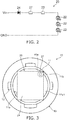
- FIG. 2 is a circuit diagram illustrating a light-emitting module 20.
- the vehicle luminaire 1 has a socket 10, a power-supply unit 30, a light-emitting module 20, and a temperature control unit 40.
- the socket 10 has a mount portion 11, a bayonet 12, a flange 13, and a thermal radiation fin 14.
- the mount portion 11 is provided on a side of the flange 13 opposite to a side where the thermal radiation fin 14 is provided.
- An exterior shape of the mount portion 11 may be a columnar shape.
- the exterior shape of the mount portion 11 is, for example, a cylindrical shape.
- the mount portion 11 has a housing portion 11a hollowed and opened to an end opposite to the flange 13 side.
- the mount portion 11 may have at least one slit 11b. Corners of the board 21 are provided in the inside of the slits 11b. A dimension (width) of the slit 11b in a circumferential direction of the mount portion 11 is slightly larger than that of the corner of the board 21. For this reason, the board 21 is positioned by inserting the corner of the board 21 into the inside of the slit 11b.
- the slit 11b is provided, it is possible to enlarge a planar shape of the board 21. For this reason, it is possible to increase the number of elements mounted on the board 21. In addition, since the exterior dimension of the mount portion 11 can be reduced, it is possible to facilitate miniaturization of the mount portion 11 and further, miniaturization of the vehicle luminaire 1.
- a plurality of bayonets 12 are provided on an outer side surface of the mount portion 11. A plurality of bayonets 12 protrude outward of the vehicle luminaire 1. A plurality of bayonets 12 face the flange 13. A plurality of bayonets 12 are used to install the vehicle luminaire 1 in a casing 101 of a vehicle lamp device 100. A plurality of bayonets 12 are used for twist locking.
- the flange 13 has a plate shape.
- the flange 13 may have, for example, a disk shape.
- An outer side surface of the flange 13 is located outward of the vehicle luminaire 1 relative to an outer side surface of the bayonet 12.
- the thermal radiation fin 14 is provided on a side of the flange 13 opposite to the mount portion 11 side. At least one thermal radiation fin 14 may be provided.
- the socket 10 of FIG. 1 is provided with a plurality of thermal radiation fins. A plurality of thermal radiation fins 14 may be arranged side by side along a predetermined direction.
- the thermal radiation fins 14 may have a plate shape.
- the socket 10 further has holes 10a and 10b.
- One end of the hole 10a is opened to a bottom face 11a1 of the housing portion 11a.
- An insulating portion 32 is provided inside the hole 10a.
- One end of the hole 10b is connected to the other end of the hole 10a.
- the other end of the hole 10b is opened to the thermal radiation fin 14 side of the socket 10.
- a connector 105 having a seal member 105a is inserted into the hole 10b. For this reason, a cross-sectional shape of the hole 10b is formed to match a cross-sectional shape of the connector 105 having the seal member 105a.
- the heat generated in the light-emitting module 20 is principally transferred to the thermal radiation fins 14 via the mount portion 11 and the flange 13.
- the heat transferred to the thermal radiation fins 14 are radiated to the outside from the thermal radiation fins 14.
- the socket 10 can efficiently radiate the heat generated in the light-emitting module 20 and is preferably light-weighted.
- the socket 10 is preferably formed of a material having a high heat conductivity.
- the material having a high thermal conductivity may include, for example, metal such as aluminum or an aluminum alloy, high thermal conductivity resin, or the like.
- the high thermal conductivity resin is obtained by mixing a filler using an inorganic material with resin such as polyethylene terephthalate (PET), polybutylene terephthalate (PBT), or nylon.
- the filler may include, for example, ceramics such as aluminum oxide, carbon, or the like.
- the mount portion 11, the bayonets 12, the flange 13, and the thermal radiation fins 14 may be integrally molded through die casting, injection molding, or the like. By integrally molding these elements, it is possible to facilitate heat transfer and thus improve a heat radiation property. In addition, it is possible to facilitate manufacturing cost reduction, miniaturization, weight reduction, or the like.
- the power-supply unit 30 has a plurality of power-supply terminals 31 and an insulating portion 32.
- a plurality of power-supply terminals 31 may be formed, for example, in a bar shape. A plurality of power-supply terminals 31 protrude from the bottom face 11a1 of the housing portion 11a. A plurality of power-supply terminals 31 may be arranged side by side along a predetermined direction. A plurality of power-supply terminals 31 are provided inside the insulating portion 32. A plurality of power-supply terminals 31 extend through the inside of the insulating portion 32 and protrude from an end of the light-emitting module 20 side of the insulating portion 32 and an end of the thermal radiation fin 14 side of the insulating portion 32.
- Ends of the light-emitting module 20 side of a plurality of power-supply terminals 31 are electrically and mechanically connected to a wiring pattern 21a of the board 21. That is, one end of the power-supply terminal 31 is soldered to the wiring pattern 21a. Ends of the thermal radiation fin 14 side of a plurality of power-supply terminals 31 are exposed to the inside of the hole 10b.
- the connector 105 is fitted to a plurality of power-supply terminals 31 exposed to the inside of the hole 10b.
- the power-supply terminal 31 has an electric conductivity.
- the power-supply terminal 31 may be formed of, for example, metal such as a copper alloy. Note that the number, shape, arrangement, material, or the like of the power-supply terminal 31 are not limited to those illustrated, but may be appropriately changed.
- the socket 10 is preferably formed of a material having a high heat conductivity.
- the material having a high heat conductivity has an electric conductivity in some cases.
- the high thermal conductivity resin or the like containing a filler formed of carbon has an electric conductivity.
- the insulating portion 32 is provided to insulate the power-supply terminal 31 from the conductive socket 10.
- the insulating portion 32 also has a function of holding a plurality of power-supply terminals 31.
- the socket 10 is formed of high thermal conductivity resin having an insulating property (such as high thermal conductivity resin including a filler formed of ceramics or the like)
- the insulating portion 32 may be omitted. In this case, the socket 10 holds a plurality of power-supply terminals 31
- the insulating portion 32 is provided between a plurality of power-supply terminals 31 and the socket 10.
- the insulating portion 32 has an insulating property.
- the insulating portion 32 may be formed of resin having an insulating property.
- the insulating portion 32 may be formed of, for example, PET, nylon, or the like.
- the insulating portion 32 is provided inside the hole 10a of the socket 10.
- the light-emitting module 20 is provided in one end of the socket 10.
- the light-emitting module 20 may be provided inside the housing portion 11a.
- the light-emitting module 20 has a board 21, a light-emitting element 22, a resistance 23, a diode 24, a frame 25, a sealing portion 26, and a control element 27.
- the board 21 is provided inside the housing portion 11a.
- the board 21 may be provided, for example, on the bottom face 11a1 of the housing portion 11a.
- the board 21 has a plate shape.
- the planar shape of the board 21 may be, for example, a rectangular shape.
- a material or structure of the board 21 is not particularly limited.
- the board 21 may be formed of an inorganic material such as ceramics (for example, aluminum oxide, aluminum nitride, or the like), an organic material such as paper phenol or glass epoxy, or the like.
- the board 21 may be formed by coating an insulating material on a surface of a metal plate.
- the insulating material may contain either an organic material or an inorganic material.
- the board 21 is preferably formed of a material having a high heat conductivity from the viewpoint of heat radiation.
- the material having a high heat conductivity may include, for example, ceramics such as aluminum oxide or aluminum nitride, high thermal conductivity resin, a metal plate coated with an insulating material, or the like.
- the board 21 may have either a single layer structure or a multilayer structure.
- a wiring pattern 21a is provided on a surface of the board 21.
- the wiring pattern 21a may be formed of, for example, a material containing copper as a main component.
- the material of the wiring pattern 21a is not limited to the material containing copper as a main component.
- the wiring pattern 21a may be formed of, for example, a material containing silver as a main component, or the like.
- the wiring pattern 21a may be formed of, for example, silver or a silver alloy.
- the light-emitting element 22 is provided on a face of the board 21 opposite to the bottom face 11a1 side of the housing portion 11a.
- the light-emitting element 22 is provided on the board 21.
- the light-emitting element 22 is electrically connected to the wiring pattern 21a provided on a surface of the board 21.
- the light-emitting element 22 may include, for example, a light-emitting diode, an organic light-emitting diode, a laser diode, or the like. At least one light-emitting element 22 may be provided.
- the light-emitting module 20 of FIGS. 1 and 2 has a plurality of light-emitting elements 22. A plurality of light-emitting elements 22 may be connected to each other in series.
- the light-emitting element 22 may be a chip type light-emitting element.
- the chip type light-emitting element 22 is embedded in a chip-on-board (COB).
- COB chip-on-board
- the light-emitting element 22 is electrically connected to the wiring pattern 21a with a wire 21b.
- the light-emitting element 22 and the wiring pattern 21a may be electrically connected, for example, using a wire bonding method.
- the light-emitting element 22 may be an upper/lower electrode type light-emitting element, an upper electrode type light-emitting element, a flip-chip type light-emitting element, or the like. Note that the light-emitting element 22 of FIG. 1 is the upper/lower electrode type light-emitting element. When the light-emitting element 22 is the flip-chip type light-emitting element, the light-emitting element 22 is directly connected to the wiring pattern 21a.
- the light-emitting element 22 may be a surface-mounted light-emitting element or a shell type light-emitting element having a lead wire.
- the resistance 23 is provided on a face of the board 21 opposite to the bottom face 11a1 side of the housing portion 11a.
- the resistance 23 is provided on the board 21.
- the resistance 23 is electrically connected to the wiring pattern 21a provided on a surface of the board 21.
- the resistance 23 is electrically connected to the light-emitting element 22.
- At least one resistance 23 may be provided.
- the resistance 23 may be, for example, a surface-mounted resistor, a resistor having a lead wire (metal oxide film resistor), a film type resistor formed by a screen print method, or the like. Note that the resistance 23 of FIG. 1 is a surface-mounted resistor.
- a forward bias characteristic of the light-emitting element 22 since a forward bias characteristic of the light-emitting element 22 has a variation, a variation occurs in brightness (light flux, luminance, light intensity, or illuminance) of light irradiated from the light-emitting element 22 when a constant voltage is applied between an anode terminal and a ground terminal. For this reason, a current value flowing to the light-emitting element 22 is controlled to a predetermined range using the resistance 23 such that the brightness of light emitted from the light-emitting element 22 is within a predetermined range. In this case, the current value flowing through the light-emitting element 22 is controlled to a predetermined range by changing a resistance value of the resistance 23.
- a resistance 23 having a suitable resistance value is selected depending on a forward bias characteristic of the light-emitting element 22.
- the resistance 23 is a film type resistor, the resistance value can increase by removing a part of the resistance 23. For example, a part of the resistance 23 can be easily removed by irradiating the resistance 23 with laser light.
- the diode 24 is provided on a face of the board 21 opposite to the bottom face 11a1 side of the housing portion 11a.
- the diode 24 is provided on the board 21.
- the diode 24 is electrically connected to the wiring pattern 21a provided on a surface of the board 21.
- the diode 24 is electrically connected to the light-emitting element 22.
- the diode 24 is provided to prevent a reverse voltage from being applied to the light-emitting element 22 and prevent a reverse pulse noise from being applied to the light-emitting element 22.
- the diode 24 may include, for example, a surface-mounted diode, a diode having a lead wire, or the like.
- the diode 24 of FIG. 1 is a surface-mounted diode.
- a frame 25 and a sealing portion 26 may be provided.
- the frame 25 may be provided on a face of the board 21 opposite to the bottom face 11a1 side of the housing portion 11a.
- the frame 25 may be provided on the board 21.
- the frame 25 may be bonded to the board 21.
- the frame 25 has, for example, an annular shape to accommodate a plurality of light-emitting elements 22 therein. That is, the frame 25 may surround a plurality of light-emitting elements 22.
- the frame 25 may be formed of resin.
- the resin may include, for example, thermoplastic resin such as PBT, polycarbonate (PC), PET, nylon, polypropylene (PP), polyethylene (PE), or polystyrene (PS).
- a reflectance to the light emitted from the light-emitting element 22 may be improved by mixing particles such as titanium oxide with the resin. Note that any particle formed of a material having a high reflectance to the light emitted from the light-emitting element 22 may be mixed without limiting to the titanium oxide particle.
- the frame 25 may be formed of, for example, white resin.
- the inner wall surface of the frame 25 is sloped to be widened from a center axis of the frame 25 as a distance from the board 21 increases. For this reason, a part of the light emitted from the light-emitting element 22 is reflected on the inner wall surface of the frame 25 and is emitted toward a front face side of the vehicle luminaire 1. That is, the frame 25 may have a function of defining a range of the sealing portion 26 and a function of a reflector.
- the sealing portion 26 is provided in the inside of the frame 25.
- the sealing portion 26 is provided to cover the inside of the frame 25. That is, the sealing portion 26 is provided in the inside of the frame 25 to cover the light-emitting element 22 or the wire 21b.
- the sealing portion 26 is formed of a light transmissive material.
- the sealing portion 26 may be formed, for example, by filling resin in the inside of the frame 25.
- the resin may be filled using a liquid quantitative discharge device such as a dispenser.
- the resin to be filled may include, for example, silicon resin or the like.
- the sealing portion 26 may contain phosphor.
- the phosphor may include, for example, yttrium-aluminum-garnet-based (YAG-based) phosphor.
- YAG-based yttrium-aluminum-garnet-based
- the type of the phosphor may be appropriately changed such that a desired luminescent color can be obtained depending on the use purpose of the vehicle luminaire 1 or the like.
- sealing portion 26 may be provided without the frame 25.
- a dome-shaped sealing portion 26 is provided on the board 21.
- the control element 27 is provided on a face of the board 21 opposite to the bottom face 11a1 side of the housing portion 11a.
- the control element 27 is provided on the board 21.
- the control element 27 is electrically connected to the wiring pattern 21a provided on a surface of the board 21.
- the control element 27 is electrically connected to the light-emitting element 22.
- the control element 27 may have an electric resistance increasing as a temperature rises.
- the control element 27 may be, for example, a positive temperature coefficient thermistor. When the control element 27 is a positive temperature coefficient thermistor, the resistance value of the control element 27 increases when the temperature of the control element 27 exceeds the Curie point.
- control element 27 is a positive temperature coefficient thermistor by way of example.
- At least one control element 27 may be provided.
- the number of the control elements 27 may be appropriately changed depending on a total current value to be set.
- a plurality of control elements 27 may be connected to each other in parallel.
- a plurality of control elements 27 connected in parallel may be connected in series to a plurality of light-emitting elements 22 connected in series.
- a voltage is applied to the light-emitting module 20 in order to light the vehicle luminaire 1. Then, a current flows to the light-emitting element 22, and heat is generated, so that the temperature of the light-emitting element 22 increases.
- the vehicle luminaire 1 has a battery as a power-supply.
- the voltage applied to the vehicle luminaire 1 fluctuates.
- an operational standard voltage (rated voltage) of the vehicle luminaire 1 of a typical vehicle is set to 13.5 V or so.
- a voltage higher than the rated voltage may be applied in some cases.
- the temperature of the light-emitting element 22 excessively increases, so that the light-emitting element 22 may be failed, or a service life of the light-emitting element 22 may be reduced.
- the light-emitting module 20 has the control element 27.
- a voltage is applied to the vehicle luminaire 1 (light-emitting module 20), and a current flows to the control element 27, Joule heat is generated, and the temperature of the control element 27 increases.
- the temperature of the control element 27 increases accordingly.
- the resistance value of the control element 27 increases.
- the control element 27 may be selected such that the resistance value does not increase until the input voltage Vin reaches 12 to 14.5 V.
- the aforementioned example is based on a case where self-heating of the control element 27 is taken into consideration.
- the Joule heat is generated from the light-emitting element 22 or the resistance 23, and a part of the generated heat is transferred to the control element 27 via the board 21 or the socket 10 (mount portion 11). That is, the temperature of the control element 27 is influenced by self-heating and thermal interference of the light-emitting element 22 or the like. Since the self-heating is almost determined by the input voltage Vin, a variation is insignificant even when the specification, size, use purpose, or the like of the vehicle luminaire 1 changes. In comparison, the thermal interference may change significantly when the numbers or specifications of the light-emitting element 22 and the resistance 23, a distance between the light-emitting element 22 and the control element 27, or the like change.
- a control element 27 having a suitable Curie point and a suitable resistance value may be selected in consideration of the self-heating and the thermal interference.
- a plurality of types of control elements 27 are necessary depending on the specification of the vehicle luminaire 1.
- the vehicle luminaire 1 has a temperature control unit 40.
- the temperature control unit 40 controls the heat generated from at least one of the light-emitting element 22 and the resistance 23 and transferred to the control element 27 via the board 21 or via the board 21 and the mount portion 11.
- the temperature control unit 40 has at least one of a hole, a hollow, and a notch provided in the board 21.
- the hole may penetrate a thickness direction of the board 21.
- the hollow may be, for example, a bottomed hole.
- the notch may be, for example, a hole or hollow opened to a peripheral edge of the board 21.
- the temperature control unit 40 of FIG. 1 is a hole penetrating the thickness direction of the board 21.
- the temperature control unit 40 may be provided in at least between the light-emitting element 22 and the control element 27 or between the resistance 23 and the control element 27. Since, in general, a heat generation amount of the light-emitting element 22 is larger than that of the resistance 23, the temperature control unit 40 is preferably provided at least between the light-emitting element 22 and the control element 27.
- the temperature control unit 40 of FIG. 1 is provided between the light-emitting element 22 and the control element 27 and between the resistance 23 and the control element 27.
- a material having a heat conductivity lower than that of the material of the board 21 may be filled in the inside of the temperature control unit 40.
- the inside of the temperature control unit 40 may be filled with air. That is, the inside of the temperature control unit 40 may be a cavity.
- the inside of the temperature control unit 40 may be filled with a material having a low heat conductivity such as resin.
- the inside of the temperature control unit 40 is a cavity, it is possible to reduce influence of thermal interference and reduce a manufacturing cost.
- the inside of the temperature control unit 40 may be filled with a material having a heat conductivity higher than that of the material of the board 21. As a result, it is possible to easily transfer heat to the control element 27. For example, when it is necessary to use the control element 27 having a Curie point higher than a desired Curie point, it is preferable to increase influence of the thermal interference to easily increase the temperature of the control element 27.
- the inside of the temperature control unit 40 may be filled with metal such as copper or aluminum.
- the inside of the temperature control unit 40 may be filled with a material having a heat conductivity different from that of the material of the board 21.
- the size of the vehicle luminaire 1 tends to decrease, that is, miniaturization of the light-emitting module 20 is progressing.
- the luminance of the light-emitting module 20 is also increasing. For this reason, influence of the thermal interference tends to increase. Therefore, the inside of the temperature control unit 40 is preferably filled with a material having a heat conductivity lower than that of the material of the board 21.
- a planar size, a planar shape, and the number of the temperature control unit 40, a distance between the control element 27 and the temperature control unit 40, the material to be filled, and the like may be appropriately determined by performing experiments, simulations, or the like.
- the temperature control unit 40 when the temperature control unit 40 is provided, it is possible to control the heat transferred to the control element 27 via the board 21 and further to control the temperature of the control element 27. For this reason, even when the specification or the like of the vehicle luminaire 1 changes, the control element 27 can operate at a desired temperature, so that it is possible to share the control element 27. As a result, it is possible to reduce the types of the control elements 27 to be stocked, and thus reduce the manufacturing cost of the vehicle luminaire 1.
- FIG. 3 is a schematic plan view illustrating a temperature control unit 40a according to another embodiment.
- the light-emitting element 22, the resistance 23, the diode 24, the frame 25, the sealing portion 26, and the like are omitted for simplicity purposes.
- the temperature control unit 40a may be provided on the bottom face 11a1 of the housing portion 11a.
- the temperature control unit 40a has at least one of a hole, a hollow, and a notch provided on the bottom face 11a1.
- the hole may penetrate, for example, a center axis direction of the socket 10.
- the hollow may be, for example, a bottomed hole.
- the notch may be, for example, a hole or hollow opened to the outer surface of the mount portion 11.
- the temperature control unit 40a of FIG. 3 is a hollow provided on the bottom face 11a1.
- the temperature control unit 40a may be provided at least in a position of the control element 27, between the light-emitting element 22 and the control element 27, or between the resistance 23 and the control element 27. In this case, if the temperature control unit 40a is provided in the position of the control element 27 as seen in a plan view, it is possible to control both the heat from the light-emitting element 22 and the heat from the resistance 23.
- the temperature control unit 40a of FIG. 3 is a hollow provided in the position of the control element 27 as seen in a plan view.
- the inside of the temperature control unit 40a may be filled with a material having a heat conductivity lower than that of the material of the mount portion 11, or a material having a heat conductivity higher than that of the material of the mount portion 11. That is, the inside of the temperature control unit 40a may be filled with a material having a heat conductivity different from that of the material of the mount portion 11.
- the temperature control unit 40a may be shaped to extend between the light-emitting element 22 and the control element 27 or between the resistance 23 and the control element 27 as seen in a plan view.
- the inside of the temperature control unit 40a is preferably filled with a material having a heat conductivity lower than that of the material of the mount portion 11.
- the material to be filled may be similar to, for example, that of the temperature control unit 40 described above.
- a planar size, a planar shape, and the number of the temperature control unit 40a, a distance between the control element 27 and the temperature control unit 40a, the material to be filled, and the like may be appropriately determined by performing experiments, simulations, or the like.
- the temperature control unit 40a when the temperature control unit 40a is provided, it is possible to control the heat transferred to the control element 27 via the mount portion 11 and further to control the temperature of the control element 27. For this reason, even when the specification or the like of the vehicle luminaire 1 changes, the control element 27 can operate at a desired temperature, so that it is possible to share the control element 27. As a result, it is possible to reduce the types of the control elements 27 to be stocked, and thus reduce the manufacturing cost of the vehicle luminaire 1.
- FIG. 4 is a schematic plan view illustrating a temperature control unit 40b according to further another embodiment.
- the temperature control unit 40b may be provided between the board 21 and the control element 27.
- the temperature control unit 40b may be provided between a side face of the control element 27 and the board 21.
- the temperature control unit 40b may have a heat conductivity different from that of the material of the board 21. As described above, since the thermal interference tends to increase in recent years, the heat conductivity of the material of the temperature control unit 40b is preferably lower than that of the material of the board 21.
- the temperature control unit 40b may be formed using a conductive adhesive instead of the solder. Note that the temperature control unit 40b may be a sheet or the like provided between the lower face of the control element 27 and the board 21.
- a size, a shape, a material, and the number, or the like of the temperature control unit 40b may be appropriately determined by performing experiments, simulations, or the like.
- the temperature control unit 40b when the temperature control unit 40b is provided, it is possible to control the heat transferred to the control element 27 via the board 21 and further to control the temperature of the control element 27. For this reason, even when the specification or the like of the vehicle luminaire 1 changes, the control element 27 can operate at a desired temperature, so that it is possible to share the control element 27. As a result, it is possible to reduce the types of the control elements 27 to be stocked, and thus reduce the manufacturing cost of the vehicle luminaire 1.
- temperature control units 40, 40a, and 40b may be combined with each other.
- the vehicle lamp device 100 is a front combination light provided in an automobile.
- the vehicle lamp device 100 is not limited to the front combination light provided in an automobile.
- the vehicle lamp device 100 may be a vehicle lamp device provided in an automobile, a railroad vehicle, or the like.
- FIG. 5 is a schematic partial cross-sectional view illustrating the vehicle lamp device 100.
- the vehicle lamp device 100 has a vehicle luminaire 1, a casing 101, a cover 102, an optical element unit 103, a seal member 104, and a connector 105.
- the vehicle luminaire 1 is installed in the casing 101.
- the casing 101 holds the mount portion 11.
- the casing 101 has a box shape whose one end side is opened.
- the casing 101 may be formed of, for example, resin or the like that does not transmit light.
- a bottom face of the casing 101 is provided with an installation hole 101a into which a part of the mount portion 11 where the bayonet 12 is provided is inserted.
- a peripheral edge of the installation hole 101a has a hollow into which the bayonet 12 of the mount portion 11 is inserted. Note that, although it is assumed that the installation hole 101a is directly provided in the casing 101 in this case, an installation member of the installation hole 101a may be provided in the casing 101.
- the cover 102 is provided to block the opening of the casing 101.
- the cover 102 may be formed of light transmissive resin or the like.
- the cover 102 may have a function of a lens or the like.
- the light emitted from the vehicle luminaire 1 is incident to the optical element unit 103.
- the optical element unit 103 performs reflection, diffusion, light guiding, condensation, formation of a predetermined luminous intensity distribution pattern, or the like for the light emitted from the vehicle luminaire 1.
- the optical element unit 103 of FIG. 5 is a reflector.
- the optical element unit 103 reflects the light emitted from the vehicle luminaire 1 to form a predetermined luminous intensity distribution pattern.
- the seal member 104 is provided between the flange 13 and the casing 101.
- the seal member 104 may have an annular shape.
- the seal member 104 may be formed of a material having elasticity such as rubber or silicon resin.
- the seal member 104 is interposed between the flange 13 and the casing 101. For this reason, the internal space of the casing 101 is sealed by the seal member 104. In addition, the bayonet 12 is pressed to the casing 101 by virtue of an elastic force of the seal member 104. For this reason, it is possible to suppress the vehicle luminaire 1 from being uninstalled from the casing 101.
- the connector 105 is fitted to ends of a plurality of power-supply terminals 31 exposed to the inside of the hole 10b.
- a power-supply or the like (not shown) is electrically connected to the connector 105. For this reason, by fitting the connector 105 to ends of a plurality of power-supply terminals 31, the power-supply or the like (not shown) and the light-emitting element 22 are electrically connected to each other.
- the connector 105 has a stepped portion.
- the seal member 105a is installed in the stepped portion.
- the seal member 105a is provided to prevent water from intruding to the inside of the hole 10b.
- the seal member 105a may have an annular shape.
- the seal member 105a may be formed of an elastic material such as rubber or silicon resin.
- the connector 105 may be bonded to an element of the socket 10 side, for example, using an adhesive or the like.
Landscapes
- Engineering & Computer Science (AREA)
- General Engineering & Computer Science (AREA)
- Microelectronics & Electronic Packaging (AREA)
- Physics & Mathematics (AREA)
- Optics & Photonics (AREA)
- Non-Portable Lighting Devices Or Systems Thereof (AREA)
- Arrangement Of Elements, Cooling, Sealing, Or The Like Of Lighting Devices (AREA)
- Lighting Device Outwards From Vehicle And Optical Signal (AREA)
Applications Claiming Priority (1)
| Application Number | Priority Date | Filing Date | Title |
|---|---|---|---|
| JP2018115807A JP7079425B2 (ja) | 2018-06-19 | 2018-06-19 | 車両用照明装置、および車両用灯具 |
Publications (2)
| Publication Number | Publication Date |
|---|---|
| EP3584497A1 true EP3584497A1 (de) | 2019-12-25 |
| EP3584497B1 EP3584497B1 (de) | 2021-02-17 |
Family
ID=65199343
Family Applications (1)
| Application Number | Title | Priority Date | Filing Date |
|---|---|---|---|
| EP19152957.7A Active EP3584497B1 (de) | 2018-06-19 | 2019-01-22 | Fahrzeugleuchte und fahrzeuglampenvorrichtung |
Country Status (4)
| Country | Link |
|---|---|
| US (1) | US10655814B2 (de) |
| EP (1) | EP3584497B1 (de) |
| JP (1) | JP7079425B2 (de) |
| CN (1) | CN209341137U (de) |
Cited By (1)
| Publication number | Priority date | Publication date | Assignee | Title |
|---|---|---|---|---|
| EP3889496A1 (de) * | 2020-04-02 | 2021-10-06 | Toshiba Lighting & Technology Corporation | Fahrzeugleuchte und fahrzeugbeleuchtungswerkzeug |
Families Citing this family (3)
| Publication number | Priority date | Publication date | Assignee | Title |
|---|---|---|---|---|
| KR102514901B1 (ko) * | 2018-09-07 | 2023-03-29 | 루미레즈 엘엘씨 | 회로 보드를 포함하는 조명 디바이스 |
| JP2020113506A (ja) * | 2019-01-16 | 2020-07-27 | 東芝ライテック株式会社 | 車両用照明装置、および車両用灯具 |
| JP2022180740A (ja) * | 2021-05-25 | 2022-12-07 | 東芝ライテック株式会社 | 車両用照明装置、および車両用灯具 |
Citations (7)
| Publication number | Priority date | Publication date | Assignee | Title |
|---|---|---|---|---|
| DE102005018175A1 (de) * | 2005-04-19 | 2006-10-26 | Patent-Treuhand-Gesellschaft für elektrische Glühlampen mbH | LED-Modul und LED-Beleuchtungseinrichtung mit mehreren LED-Modulen |
| US20080143275A1 (en) * | 2006-12-19 | 2008-06-19 | Eveready Battery Company | Positive temperature coefficient light emitting diode light |
| US20120161633A1 (en) * | 2010-12-27 | 2012-06-28 | Denso Corporation | Lighting apparatus and lighting fitting |
| US20130193851A1 (en) * | 2012-01-26 | 2013-08-01 | Vishay Dale Electronics, Inc. | Integrated Circuit Element and Electronic Circuit for Light Emitting Diode Applications |
| US20140160773A1 (en) * | 2011-08-02 | 2014-06-12 | Koninklijke Philips N.V. | Modular lighting assembly adapter part |
| EP3118059A1 (de) * | 2015-07-10 | 2017-01-18 | Toshiba Lighting & Technology Corporation | Lichtemittierende vorrichtung für ein fahrzeug, beleuchtungsvorrichtung für ein fahrzeug und beleuchtungswerkzeug für ein fahrzeug |
| JP2017159726A (ja) * | 2016-03-08 | 2017-09-14 | 東芝ライテック株式会社 | 車両用照明装置および車両用灯具 |
Family Cites Families (4)
| Publication number | Priority date | Publication date | Assignee | Title |
|---|---|---|---|---|
| JP2000278859A (ja) | 1999-03-24 | 2000-10-06 | Stanley Electric Co Ltd | Led点灯回路の過電圧保護回路 |
| JP6052573B2 (ja) * | 2012-04-11 | 2016-12-27 | 東芝ライテック株式会社 | 光半導体光源及び車両用照明装置 |
| JP6458991B2 (ja) * | 2015-02-23 | 2019-01-30 | 東芝ライテック株式会社 | 車両用照明装置および車両用灯具 |
| EP3200562A1 (de) * | 2016-02-01 | 2017-08-02 | Toshiba Lighting & Technology Corporation | Fahrzeugbeleuchtungsvorrichtung und fahrzeuglampe |
-
2018
- 2018-06-19 JP JP2018115807A patent/JP7079425B2/ja active Active
-
2019
- 2019-01-22 EP EP19152957.7A patent/EP3584497B1/de active Active
- 2019-01-23 US US16/255,450 patent/US10655814B2/en active Active
- 2019-02-15 CN CN201920201222.8U patent/CN209341137U/zh active Active
Patent Citations (7)
| Publication number | Priority date | Publication date | Assignee | Title |
|---|---|---|---|---|
| DE102005018175A1 (de) * | 2005-04-19 | 2006-10-26 | Patent-Treuhand-Gesellschaft für elektrische Glühlampen mbH | LED-Modul und LED-Beleuchtungseinrichtung mit mehreren LED-Modulen |
| US20080143275A1 (en) * | 2006-12-19 | 2008-06-19 | Eveready Battery Company | Positive temperature coefficient light emitting diode light |
| US20120161633A1 (en) * | 2010-12-27 | 2012-06-28 | Denso Corporation | Lighting apparatus and lighting fitting |
| US20140160773A1 (en) * | 2011-08-02 | 2014-06-12 | Koninklijke Philips N.V. | Modular lighting assembly adapter part |
| US20130193851A1 (en) * | 2012-01-26 | 2013-08-01 | Vishay Dale Electronics, Inc. | Integrated Circuit Element and Electronic Circuit for Light Emitting Diode Applications |
| EP3118059A1 (de) * | 2015-07-10 | 2017-01-18 | Toshiba Lighting & Technology Corporation | Lichtemittierende vorrichtung für ein fahrzeug, beleuchtungsvorrichtung für ein fahrzeug und beleuchtungswerkzeug für ein fahrzeug |
| JP2017159726A (ja) * | 2016-03-08 | 2017-09-14 | 東芝ライテック株式会社 | 車両用照明装置および車両用灯具 |
Cited By (2)
| Publication number | Priority date | Publication date | Assignee | Title |
|---|---|---|---|---|
| EP3889496A1 (de) * | 2020-04-02 | 2021-10-06 | Toshiba Lighting & Technology Corporation | Fahrzeugleuchte und fahrzeugbeleuchtungswerkzeug |
| US11788706B2 (en) | 2020-04-02 | 2023-10-17 | Toshiba Lighting & Technology Corporation | Vehicle luminaire and vehicle lighting tool |
Also Published As
| Publication number | Publication date |
|---|---|
| EP3584497B1 (de) | 2021-02-17 |
| US10655814B2 (en) | 2020-05-19 |
| US20190383463A1 (en) | 2019-12-19 |
| CN209341137U (zh) | 2019-09-03 |
| JP7079425B2 (ja) | 2022-06-02 |
| JP2019217872A (ja) | 2019-12-26 |
Similar Documents
| Publication | Publication Date | Title |
|---|---|---|
| EP3531014A1 (de) | Fahrzeugleuchte, fahrzeuglampe und verfahren zur herstellung einer fahrzeugleuchte | |
| EP3584497B1 (de) | Fahrzeugleuchte und fahrzeuglampenvorrichtung | |
| EP3587908A1 (de) | Fahrzeugleuchte und fahrzeuglampenvorrichtung | |
| EP3249290B1 (de) | Fahrzeugbeleuchtungsvorrichtung und fahrzeuglampe | |
| JP6880507B2 (ja) | 車両用照明装置、および車両用灯具 | |
| EP3537033B1 (de) | Fahrzeugleuchte, fahrzeuglampe und verfahren zur herstellung einer fahrzeugleuchte | |
| US20200355342A1 (en) | Vehicle Luminaire and Vehicle Lamp | |
| EP3460317B1 (de) | Fahrzeugbeleuchtungsvorrichtung und fahrzeuglampe | |
| JP6930332B2 (ja) | 車両用照明装置、および車両用灯具 | |
| JP2020187979A (ja) | 車両用照明装置、および車両用灯具 | |
| JP2019053849A (ja) | 車両用照明装置、および車両用灯具 | |
| US12253233B2 (en) | Vehicle lighting device and vehicle lamp | |
| JP7112675B2 (ja) | 車両用照明装置、車両用灯具、および車両用照明装置の製造方法 | |
| EP3829269B1 (de) | Fahrzeugleuchte und fahrzeuglampe | |
| JP2020017350A (ja) | 車両用照明装置、および車両用灯具 | |
| JP2019212573A (ja) | 車両用照明装置、および車両用灯具 | |
| JP6960103B2 (ja) | 車両用照明装置、および車両用灯具 | |
| JP6944648B2 (ja) | 車両用照明装置、車両用灯具、およびソケットの製造方法 | |
| JP2023175148A (ja) | 車両用照明装置、および車両用灯具 | |
| JP2019153522A (ja) | 車両用照明装置、および車両用灯具 | |
| JP2019061769A (ja) | 車両用照明装置のソケットモジュールの製造方法、車両用照明装置、および車両用灯具 |
Legal Events
| Date | Code | Title | Description |
|---|---|---|---|
| PUAI | Public reference made under article 153(3) epc to a published international application that has entered the european phase |
Free format text: ORIGINAL CODE: 0009012 |
|
| STAA | Information on the status of an ep patent application or granted ep patent |
Free format text: STATUS: THE APPLICATION HAS BEEN PUBLISHED |
|
| AK | Designated contracting states |
Kind code of ref document: A1 Designated state(s): AL AT BE BG CH CY CZ DE DK EE ES FI FR GB GR HR HU IE IS IT LI LT LU LV MC MK MT NL NO PL PT RO RS SE SI SK SM TR |
|
| AX | Request for extension of the european patent |
Extension state: BA ME |
|
| STAA | Information on the status of an ep patent application or granted ep patent |
Free format text: STATUS: REQUEST FOR EXAMINATION WAS MADE |
|
| 17P | Request for examination filed |
Effective date: 20200528 |
|
| RBV | Designated contracting states (corrected) |
Designated state(s): AL AT BE BG CH CY CZ DE DK EE ES FI FR GB GR HR HU IE IS IT LI LT LU LV MC MK MT NL NO PL PT RO RS SE SI SK SM TR |
|
| REG | Reference to a national code |
Ref country code: DE Ref legal event code: R079 Ref document number: 602019002429 Country of ref document: DE Free format text: PREVIOUS MAIN CLASS: F21S0043190000 Ipc: H05B0045500000 |
|
| GRAP | Despatch of communication of intention to grant a patent |
Free format text: ORIGINAL CODE: EPIDOSNIGR1 |
|
| STAA | Information on the status of an ep patent application or granted ep patent |
Free format text: STATUS: GRANT OF PATENT IS INTENDED |
|
| RIC1 | Information provided on ipc code assigned before grant |
Ipc: F21S 43/14 20180101ALI20200922BHEP Ipc: F21S 43/19 20180101ALI20200922BHEP Ipc: H05B 45/50 20200101AFI20200922BHEP Ipc: F21S 41/143 20180101ALI20200922BHEP Ipc: F21S 45/47 20180101ALI20200922BHEP Ipc: F21S 45/10 20180101ALI20200922BHEP Ipc: F21S 41/19 20180101ALI20200922BHEP |
|
| INTG | Intention to grant announced |
Effective date: 20201007 |
|
| GRAS | Grant fee paid |
Free format text: ORIGINAL CODE: EPIDOSNIGR3 |
|
| GRAA | (expected) grant |
Free format text: ORIGINAL CODE: 0009210 |
|
| STAA | Information on the status of an ep patent application or granted ep patent |
Free format text: STATUS: THE PATENT HAS BEEN GRANTED |
|
| AK | Designated contracting states |
Kind code of ref document: B1 Designated state(s): AL AT BE BG CH CY CZ DE DK EE ES FI FR GB GR HR HU IE IS IT LI LT LU LV MC MK MT NL NO PL PT RO RS SE SI SK SM TR |
|
| REG | Reference to a national code |
Ref country code: GB Ref legal event code: FG4D |
|
| REG | Reference to a national code |
Ref country code: CH Ref legal event code: EP |
|
| REG | Reference to a national code |
Ref country code: DE Ref legal event code: R096 Ref document number: 602019002429 Country of ref document: DE |
|
| REG | Reference to a national code |
Ref country code: AT Ref legal event code: REF Ref document number: 1363252 Country of ref document: AT Kind code of ref document: T Effective date: 20210315 |
|
| REG | Reference to a national code |
Ref country code: IE Ref legal event code: FG4D |
|
| REG | Reference to a national code |
Ref country code: DE Ref legal event code: R084 Ref document number: 602019002429 Country of ref document: DE |
|
| REG | Reference to a national code |
Ref country code: LT Ref legal event code: MG9D |
|
| REG | Reference to a national code |
Ref country code: NL Ref legal event code: MP Effective date: 20210217 |
|
| PG25 | Lapsed in a contracting state [announced via postgrant information from national office to epo] |
Ref country code: PT Free format text: LAPSE BECAUSE OF FAILURE TO SUBMIT A TRANSLATION OF THE DESCRIPTION OR TO PAY THE FEE WITHIN THE PRESCRIBED TIME-LIMIT Effective date: 20210617 Ref country code: NO Free format text: LAPSE BECAUSE OF FAILURE TO SUBMIT A TRANSLATION OF THE DESCRIPTION OR TO PAY THE FEE WITHIN THE PRESCRIBED TIME-LIMIT Effective date: 20210517 Ref country code: LT Free format text: LAPSE BECAUSE OF FAILURE TO SUBMIT A TRANSLATION OF THE DESCRIPTION OR TO PAY THE FEE WITHIN THE PRESCRIBED TIME-LIMIT Effective date: 20210217 Ref country code: FI Free format text: LAPSE BECAUSE OF FAILURE TO SUBMIT A TRANSLATION OF THE DESCRIPTION OR TO PAY THE FEE WITHIN THE PRESCRIBED TIME-LIMIT Effective date: 20210217 Ref country code: GR Free format text: LAPSE BECAUSE OF FAILURE TO SUBMIT A TRANSLATION OF THE DESCRIPTION OR TO PAY THE FEE WITHIN THE PRESCRIBED TIME-LIMIT Effective date: 20210518 Ref country code: HR Free format text: LAPSE BECAUSE OF FAILURE TO SUBMIT A TRANSLATION OF THE DESCRIPTION OR TO PAY THE FEE WITHIN THE PRESCRIBED TIME-LIMIT Effective date: 20210217 Ref country code: BG Free format text: LAPSE BECAUSE OF FAILURE TO SUBMIT A TRANSLATION OF THE DESCRIPTION OR TO PAY THE FEE WITHIN THE PRESCRIBED TIME-LIMIT Effective date: 20210517 |
|
| REG | Reference to a national code |
Ref country code: AT Ref legal event code: MK05 Ref document number: 1363252 Country of ref document: AT Kind code of ref document: T Effective date: 20210217 |
|
| PG25 | Lapsed in a contracting state [announced via postgrant information from national office to epo] |
Ref country code: SE Free format text: LAPSE BECAUSE OF FAILURE TO SUBMIT A TRANSLATION OF THE DESCRIPTION OR TO PAY THE FEE WITHIN THE PRESCRIBED TIME-LIMIT Effective date: 20210217 Ref country code: LV Free format text: LAPSE BECAUSE OF FAILURE TO SUBMIT A TRANSLATION OF THE DESCRIPTION OR TO PAY THE FEE WITHIN THE PRESCRIBED TIME-LIMIT Effective date: 20210217 Ref country code: PL Free format text: LAPSE BECAUSE OF FAILURE TO SUBMIT A TRANSLATION OF THE DESCRIPTION OR TO PAY THE FEE WITHIN THE PRESCRIBED TIME-LIMIT Effective date: 20210217 Ref country code: NL Free format text: LAPSE BECAUSE OF FAILURE TO SUBMIT A TRANSLATION OF THE DESCRIPTION OR TO PAY THE FEE WITHIN THE PRESCRIBED TIME-LIMIT Effective date: 20210217 Ref country code: RS Free format text: LAPSE BECAUSE OF FAILURE TO SUBMIT A TRANSLATION OF THE DESCRIPTION OR TO PAY THE FEE WITHIN THE PRESCRIBED TIME-LIMIT Effective date: 20210217 |
|
| PG25 | Lapsed in a contracting state [announced via postgrant information from national office to epo] |
Ref country code: IS Free format text: LAPSE BECAUSE OF FAILURE TO SUBMIT A TRANSLATION OF THE DESCRIPTION OR TO PAY THE FEE WITHIN THE PRESCRIBED TIME-LIMIT Effective date: 20210617 |
|
| PG25 | Lapsed in a contracting state [announced via postgrant information from national office to epo] |
Ref country code: EE Free format text: LAPSE BECAUSE OF FAILURE TO SUBMIT A TRANSLATION OF THE DESCRIPTION OR TO PAY THE FEE WITHIN THE PRESCRIBED TIME-LIMIT Effective date: 20210217 Ref country code: CZ Free format text: LAPSE BECAUSE OF FAILURE TO SUBMIT A TRANSLATION OF THE DESCRIPTION OR TO PAY THE FEE WITHIN THE PRESCRIBED TIME-LIMIT Effective date: 20210217 Ref country code: SM Free format text: LAPSE BECAUSE OF FAILURE TO SUBMIT A TRANSLATION OF THE DESCRIPTION OR TO PAY THE FEE WITHIN THE PRESCRIBED TIME-LIMIT Effective date: 20210217 Ref country code: AT Free format text: LAPSE BECAUSE OF FAILURE TO SUBMIT A TRANSLATION OF THE DESCRIPTION OR TO PAY THE FEE WITHIN THE PRESCRIBED TIME-LIMIT Effective date: 20210217 |
|
| REG | Reference to a national code |
Ref country code: DE Ref legal event code: R097 Ref document number: 602019002429 Country of ref document: DE |
|
| PG25 | Lapsed in a contracting state [announced via postgrant information from national office to epo] |
Ref country code: DK Free format text: LAPSE BECAUSE OF FAILURE TO SUBMIT A TRANSLATION OF THE DESCRIPTION OR TO PAY THE FEE WITHIN THE PRESCRIBED TIME-LIMIT Effective date: 20210217 Ref country code: RO Free format text: LAPSE BECAUSE OF FAILURE TO SUBMIT A TRANSLATION OF THE DESCRIPTION OR TO PAY THE FEE WITHIN THE PRESCRIBED TIME-LIMIT Effective date: 20210217 Ref country code: SK Free format text: LAPSE BECAUSE OF FAILURE TO SUBMIT A TRANSLATION OF THE DESCRIPTION OR TO PAY THE FEE WITHIN THE PRESCRIBED TIME-LIMIT Effective date: 20210217 |
|
| PLBE | No opposition filed within time limit |
Free format text: ORIGINAL CODE: 0009261 |
|
| STAA | Information on the status of an ep patent application or granted ep patent |
Free format text: STATUS: NO OPPOSITION FILED WITHIN TIME LIMIT |
|
| 26N | No opposition filed |
Effective date: 20211118 |
|
| PG25 | Lapsed in a contracting state [announced via postgrant information from national office to epo] |
Ref country code: ES Free format text: LAPSE BECAUSE OF FAILURE TO SUBMIT A TRANSLATION OF THE DESCRIPTION OR TO PAY THE FEE WITHIN THE PRESCRIBED TIME-LIMIT Effective date: 20210217 Ref country code: AL Free format text: LAPSE BECAUSE OF FAILURE TO SUBMIT A TRANSLATION OF THE DESCRIPTION OR TO PAY THE FEE WITHIN THE PRESCRIBED TIME-LIMIT Effective date: 20210217 |
|
| PG25 | Lapsed in a contracting state [announced via postgrant information from national office to epo] |
Ref country code: SI Free format text: LAPSE BECAUSE OF FAILURE TO SUBMIT A TRANSLATION OF THE DESCRIPTION OR TO PAY THE FEE WITHIN THE PRESCRIBED TIME-LIMIT Effective date: 20210217 |
|
| PG25 | Lapsed in a contracting state [announced via postgrant information from national office to epo] |
Ref country code: IT Free format text: LAPSE BECAUSE OF FAILURE TO SUBMIT A TRANSLATION OF THE DESCRIPTION OR TO PAY THE FEE WITHIN THE PRESCRIBED TIME-LIMIT Effective date: 20210217 |
|
| PG25 | Lapsed in a contracting state [announced via postgrant information from national office to epo] |
Ref country code: IS Free format text: LAPSE BECAUSE OF FAILURE TO SUBMIT A TRANSLATION OF THE DESCRIPTION OR TO PAY THE FEE WITHIN THE PRESCRIBED TIME-LIMIT Effective date: 20210617 |
|
| PG25 | Lapsed in a contracting state [announced via postgrant information from national office to epo] |
Ref country code: MC Free format text: LAPSE BECAUSE OF FAILURE TO SUBMIT A TRANSLATION OF THE DESCRIPTION OR TO PAY THE FEE WITHIN THE PRESCRIBED TIME-LIMIT Effective date: 20210217 |
|
| REG | Reference to a national code |
Ref country code: CH Ref legal event code: PL |
|
| REG | Reference to a national code |
Ref country code: BE Ref legal event code: MM Effective date: 20220131 |
|
| PG25 | Lapsed in a contracting state [announced via postgrant information from national office to epo] |
Ref country code: LU Free format text: LAPSE BECAUSE OF NON-PAYMENT OF DUE FEES Effective date: 20220122 |
|
| PG25 | Lapsed in a contracting state [announced via postgrant information from national office to epo] |
Ref country code: BE Free format text: LAPSE BECAUSE OF NON-PAYMENT OF DUE FEES Effective date: 20220131 |
|
| PG25 | Lapsed in a contracting state [announced via postgrant information from national office to epo] |
Ref country code: LI Free format text: LAPSE BECAUSE OF NON-PAYMENT OF DUE FEES Effective date: 20220131 Ref country code: CH Free format text: LAPSE BECAUSE OF NON-PAYMENT OF DUE FEES Effective date: 20220131 |
|
| PG25 | Lapsed in a contracting state [announced via postgrant information from national office to epo] |
Ref country code: IE Free format text: LAPSE BECAUSE OF NON-PAYMENT OF DUE FEES Effective date: 20220122 |
|
| GBPC | Gb: european patent ceased through non-payment of renewal fee |
Effective date: 20230122 |
|
| PG25 | Lapsed in a contracting state [announced via postgrant information from national office to epo] |
Ref country code: GB Free format text: LAPSE BECAUSE OF NON-PAYMENT OF DUE FEES Effective date: 20230122 |
|
| PG25 | Lapsed in a contracting state [announced via postgrant information from national office to epo] |
Ref country code: MK Free format text: LAPSE BECAUSE OF FAILURE TO SUBMIT A TRANSLATION OF THE DESCRIPTION OR TO PAY THE FEE WITHIN THE PRESCRIBED TIME-LIMIT Effective date: 20210217 Ref country code: CY Free format text: LAPSE BECAUSE OF FAILURE TO SUBMIT A TRANSLATION OF THE DESCRIPTION OR TO PAY THE FEE WITHIN THE PRESCRIBED TIME-LIMIT Effective date: 20210217 |
|
| PG25 | Lapsed in a contracting state [announced via postgrant information from national office to epo] |
Ref country code: HU Free format text: LAPSE BECAUSE OF FAILURE TO SUBMIT A TRANSLATION OF THE DESCRIPTION OR TO PAY THE FEE WITHIN THE PRESCRIBED TIME-LIMIT; INVALID AB INITIO Effective date: 20190122 |
|
| PG25 | Lapsed in a contracting state [announced via postgrant information from national office to epo] |
Ref country code: MT Free format text: LAPSE BECAUSE OF FAILURE TO SUBMIT A TRANSLATION OF THE DESCRIPTION OR TO PAY THE FEE WITHIN THE PRESCRIBED TIME-LIMIT Effective date: 20210217 |
|
| PG25 | Lapsed in a contracting state [announced via postgrant information from national office to epo] |
Ref country code: TR Free format text: LAPSE BECAUSE OF FAILURE TO SUBMIT A TRANSLATION OF THE DESCRIPTION OR TO PAY THE FEE WITHIN THE PRESCRIBED TIME-LIMIT Effective date: 20210217 |
|
| PGFP | Annual fee paid to national office [announced via postgrant information from national office to epo] |
Ref country code: FR Payment date: 20251209 Year of fee payment: 8 |
|
| PGFP | Annual fee paid to national office [announced via postgrant information from national office to epo] |
Ref country code: DE Payment date: 20251208 Year of fee payment: 8 |