EP3584633B1 - Dispositif optique pour vehicule comprenant un element de chauffage - Google Patents
Dispositif optique pour vehicule comprenant un element de chauffage Download PDFInfo
- Publication number
- EP3584633B1 EP3584633B1 EP19181023.3A EP19181023A EP3584633B1 EP 3584633 B1 EP3584633 B1 EP 3584633B1 EP 19181023 A EP19181023 A EP 19181023A EP 3584633 B1 EP3584633 B1 EP 3584633B1
- Authority
- EP
- European Patent Office
- Prior art keywords
- circuit board
- printed circuit
- heating strip
- electrical connection
- optical device
- Prior art date
- Legal status (The legal status is an assumption and is not a legal conclusion. Google has not performed a legal analysis and makes no representation as to the accuracy of the status listed.)
- Active
Links
Images



Classifications
-
- B—PERFORMING OPERATIONS; TRANSPORTING
- B60—VEHICLES IN GENERAL
- B60R—VEHICLES, VEHICLE FITTINGS, OR VEHICLE PARTS, NOT OTHERWISE PROVIDED FOR
- B60R1/00—Optical viewing arrangements; Real-time viewing arrangements for drivers or passengers using optical image capturing systems, e.g. cameras or video systems specially adapted for use in or on vehicles
- B60R1/02—Rear-view mirror arrangements
- B60R1/06—Rear-view mirror arrangements mounted on vehicle exterior
- B60R1/0602—Rear-view mirror arrangements mounted on vehicle exterior comprising means for cleaning or deicing
-
- G—PHYSICS
- G02—OPTICS
- G02B—OPTICAL ELEMENTS, SYSTEMS OR APPARATUS
- G02B27/00—Optical systems or apparatus not provided for by any of the groups G02B1/00 - G02B26/00, G02B30/00
- G02B27/0006—Optical systems or apparatus not provided for by any of the groups G02B1/00 - G02B26/00, G02B30/00 with means to keep optical surfaces clean, e.g. by preventing or removing dirt, stains, contamination, condensation
-
- G—PHYSICS
- G02—OPTICS
- G02B—OPTICAL ELEMENTS, SYSTEMS OR APPARATUS
- G02B7/00—Mountings, adjusting means, or light-tight connections, for optical elements
- G02B7/02—Mountings, adjusting means, or light-tight connections, for optical elements for lenses
- G02B7/028—Mountings, adjusting means, or light-tight connections, for optical elements for lenses with means for compensating for changes in temperature or for controlling the temperature; thermal stabilisation
-
- G—PHYSICS
- G03—PHOTOGRAPHY; CINEMATOGRAPHY; ANALOGOUS TECHNIQUES USING WAVES OTHER THAN OPTICAL WAVES; ELECTROGRAPHY; HOLOGRAPHY
- G03B—APPARATUS OR ARRANGEMENTS FOR TAKING PHOTOGRAPHS OR FOR PROJECTING OR VIEWING THEM; APPARATUS OR ARRANGEMENTS EMPLOYING ANALOGOUS TECHNIQUES USING WAVES OTHER THAN OPTICAL WAVES; ACCESSORIES THEREFOR
- G03B17/00—Details of cameras or camera bodies; Accessories therefor
- G03B17/02—Bodies
- G03B17/12—Bodies with means for supporting objectives, supplementary lenses, filters, masks, or turrets
-
- G—PHYSICS
- G03—PHOTOGRAPHY; CINEMATOGRAPHY; ANALOGOUS TECHNIQUES USING WAVES OTHER THAN OPTICAL WAVES; ELECTROGRAPHY; HOLOGRAPHY
- G03B—APPARATUS OR ARRANGEMENTS FOR TAKING PHOTOGRAPHS OR FOR PROJECTING OR VIEWING THEM; APPARATUS OR ARRANGEMENTS EMPLOYING ANALOGOUS TECHNIQUES USING WAVES OTHER THAN OPTICAL WAVES; ACCESSORIES THEREFOR
- G03B17/00—Details of cameras or camera bodies; Accessories therefor
- G03B17/55—Details of cameras or camera bodies; Accessories therefor with provision for heating or cooling, e.g. in aircraft
-
- H—ELECTRICITY
- H01—ELECTRIC ELEMENTS
- H01R—ELECTRICALLY-CONDUCTIVE CONNECTIONS; STRUCTURAL ASSOCIATIONS OF A PLURALITY OF MUTUALLY-INSULATED ELECTRICAL CONNECTING ELEMENTS; COUPLING DEVICES; CURRENT COLLECTORS
- H01R12/00—Structural associations of a plurality of mutually-insulated electrical connecting elements, specially adapted for printed circuits, e.g. printed circuit boards [PCB], flat or ribbon cables, or like generally planar structures, e.g. terminal strips, terminal blocks; Coupling devices specially adapted for printed circuits, flat or ribbon cables, or like generally planar structures; Terminals specially adapted for contact with, or insertion into, printed circuits, flat or ribbon cables, or like generally planar structures
- H01R12/50—Fixed connections
- H01R12/59—Fixed connections for flexible printed circuits, flat or ribbon cables or like structures
- H01R12/62—Fixed connections for flexible printed circuits, flat or ribbon cables or like structures connecting to rigid printed circuits or like structures
-
- H—ELECTRICITY
- H04—ELECTRIC COMMUNICATION TECHNIQUE
- H04N—PICTORIAL COMMUNICATION, e.g. TELEVISION
- H04N23/00—Cameras or camera modules comprising electronic image sensors; Control thereof
- H04N23/50—Constructional details
- H04N23/52—Elements optimising image sensor operation, e.g. for electromagnetic interference [EMI] protection or temperature control by heat transfer or cooling elements
-
- H—ELECTRICITY
- H04—ELECTRIC COMMUNICATION TECHNIQUE
- H04N—PICTORIAL COMMUNICATION, e.g. TELEVISION
- H04N23/00—Cameras or camera modules comprising electronic image sensors; Control thereof
- H04N23/50—Constructional details
- H04N23/54—Mounting of pick-up tubes, electronic image sensors, deviation or focusing coils
-
- H—ELECTRICITY
- H04—ELECTRIC COMMUNICATION TECHNIQUE
- H04N—PICTORIAL COMMUNICATION, e.g. TELEVISION
- H04N23/00—Cameras or camera modules comprising electronic image sensors; Control thereof
- H04N23/50—Constructional details
- H04N23/55—Optical parts specially adapted for electronic image sensors; Mounting thereof
-
- H—ELECTRICITY
- H05—ELECTRIC TECHNIQUES NOT OTHERWISE PROVIDED FOR
- H05B—ELECTRIC HEATING; ELECTRIC LIGHT SOURCES NOT OTHERWISE PROVIDED FOR; CIRCUIT ARRANGEMENTS FOR ELECTRIC LIGHT SOURCES, IN GENERAL
- H05B3/00—Ohmic-resistance heating
- H05B3/02—Details
Definitions
- the present invention relates to an optical device for a vehicle and more particularly to an optical device comprising a heating element.
- Electronic components for motor vehicles and arranged outside vehicles must withstand environmental constraints such as cold and ice. In order not to suffer the persistent effects of these constraints, these electronic components are generally equipped with electrical devices to get rid of the effects of these constraints. For example, we can find electronic components equipped with electrical devices such as heating elements to combat frost.
- Control of these electrical devices is usually achieved through electrical harnesses and connectors connecting an electronic control board and the electrical devices.
- the document WO 2018/052043 A1 discloses a low conductivity unit of a lens mount in a camera disposed between a housing tube of a lens unit and a sensor substrate.
- the low conductivity unit has a lower thermal conductivity than the housing tube.
- WO 2016/195403 A1 discloses a camera module comprising a lens barrel having a recess formed therein, including at least one lens aligned in the optical axis of the recess; a holder having formed therein an internal space in which a portion of the lens barrel is housed; a housing coupled to the holder and having formed therein an internal space in which a printed circuit board is housed; and a first heating element which is electrically connected to the printed circuit board to heat the lens.
- An optical device is defined in claim 1.
- the attachment means may include an elastic portion so as to fit the profile of the wall of the lens holder.
- the heating strip includes electrical conductors configured to carry an electrical current from the printed circuit board.
- the heating strip may be formed by a flexible printed circuit board.
- the electrical connection means may be a flexible printed circuit board type connection in substrate continuity with the heating strip.
- the electrical connection means may comprise a thinned portion of the substrate of the rigid printed circuit board.
- an orthogonal reference frame comprising a longitudinal axis L, a transverse axis T and a vertical axis V is defined. “Down”, “up”, “above”, “below”, “lower” and “upper” orientations are defined according to the vertical direction. “Left”, “right” and “lateral” orientations are defined according to the transverse direction. “Front” and “rear” orientations are also defined according to the longitudinal direction.
- an optical device 10 more particularly a vehicle camera is shown.
- This type of camera is intended to be mounted outside the vehicle and therefore subject to conditions outside the vehicle such as the climate.
- the optical device 10 comprises a protective housing 12 comprising a wall 15 of generally cylindrical shape extending along the vertical axis V from its upper end 18 to its lower end 20.
- the lower end 20 of the protective housing 12 is closed by a housing bottom 26.
- the housing bottom 26 comprises a connector body 28 extending vertically towards the outside of the protective housing 12, the connector body 28 being integral with the housing bottom 26.
- the optical device 10 comprises a lens holder 14 extending vertically in the protective housing 12.
- the lens holder 14 is an open hollow structure forming a cavity 21 extending from its upper end 19 arranged outside the protective housing 12 to its lower end 30 inserted into the protective housing 12.
- the upper end 19 of the lens holder 14 comprises an optical lens 22 aligned along the optical axis O of the optical device 10.
- the lens support 14 is held in abutment against the upper end 18 of the protective housing 12.
- the lens support 14 therefore comprises a support plate 16 arranged in abutment against the upper end 18 of the protective housing 12. protection 12.
- the lens support 14 is fixed in abutment against the upper end 18 of the protective housing 12 by means of a first adhesive seal 13 so as to hermetically close the protective housing 12.
- the support plate 16 comprises a circular opening opening onto the cavity 21 of the lens support 14 and comprising an upper wall 17 to the protective housing 12 extending vertically to the upper end 19 of the lens support 14.
- the optical lens 22 is arranged against the internal surface of the upper wall 17 and is kept aligned along the optical axis O of the optical device 10 by a retaining cap 24 fixed to the upper wall 17.
- the lens holder 14 comprises the upper wall 17 arranged over the support plate 16 and comprises a lower wall 31 to the protective housing 12 extending vertically from the support plate 16 to its lower end 30.
- the lower end 30 forms a base of generally parallelepiped shape.
- the optical device 10 comprises a first rigid printed circuit board 32.
- the first rigid printed circuit board 32 is of generally rectangular shape.
- the first printed circuit board 32 comprises on its upper face an electronic image capture circuit 36 aligned with the optical lens 22 along the optical axis O of the optical device 10.
- the printed circuit board 32 is intended to be fixed on the lower end 30 of the lens support 14 by means of a second adhesive seal 38, so as to hermetically close the cavity 21 of the lens support 14.
- the optical device 10 comprises a second rigid printed circuit board 34.
- the second printed circuit board 34 comprises on its lower face electrical terminals 40 extending vertically and intended to be inserted into the body of the connector 28.
- the second printed circuit board 34 is therefore intended to be arranged at the bottom of the housing 26 so that its electrical terminals 40 can be inserted into the body of the connector 28.
- the second printed circuit board 34 comprises electrical connection means 42 with the first printed circuit board 32.
- the second printed circuit board 34 may include electronic components for processing images received from the electronic image capture circuit 36.
- the optical device 10 comprises a flexible heating strip 50.
- the heating strip 50 is configured to be arranged around the bottom wall 31 of the lens holder 14.
- the bottom wall 31 of the lens holder 14 is an annular cylindrical wall.
- the heating strip 50 is configured to be wound around the annular bottom wall 31 of the lens holder 14 so as to be in contact with the annular wall 31 all around the latter.
- the heating strip 50 also comprises an electrical connection interface 52 intended to be electrically connected to one of the two rigid printed circuit boards 32, 34 of the optical device.
- the electrical connection interface 52 is designed to be electrically connected to the first rigid printed circuit board 32 by means of an electrical connector 63 arranged on the lower face of the first printed circuit board 32. This choice makes it possible to limit the dimension, more precisely the length, of the electrical connection interface 52.
- the heating strip 50 is arranged around the lower wall 31 of the lens holder 14.
- the heating strip 50 is arranged so as to cover the upper end 23 of the lower wall 31 of the lens holder 14 so as to be as close as possible to the upper wall of the lens holder 14 intended to receive the optical lens 22.
- the heating strip 50 comprises electrical conductors 62 configured to be traversed by an electric current coming from the first printed circuit board 32.
- the heating strip 50 is a flexible printed circuit board connected by the electrical connection interface 52 to the first printed circuit board 32.
- the electrical connection interface 52 may be a connection tab integral with the heating strip 50.
- the heating strip 50 and the associated electrical connection interface 52 are a single flexible printed circuit board, for example T-shaped, before its assembly on the lower wall 31 of the lens holder 14.
- the portion representing the base of the ⁇ T' forms the electrical connection interface 52 of the heating strip, the head of the ⁇ T' forming the heating strip 50 flexible configured to be arranged around the lower wall 31 of the lens holder 14.
- the heating strip 50, the electrical connection interface 52 and the first printed circuit board 32 may be a single printed circuit board of the flex-rigid printed circuit board type, that is to say a single printed circuit board comprising a flexible portion comprising the flexible heating strip 50 and comprising the flexible tab forming the electrical connection interface 52, said flexible portion being continuous with the substrate of the rigid main part.
- the two opposite longitudinal ends 54, 56 of the heating strip are fixed on the lower wall 31 of the lens support 14.
- the two longitudinal ends 54, 56 each comprise a strip of adhesive 53, 55 of pressure-sensitive adhesive type so as to be stuck to the lower wall 31 of the lens support 14.
- attachment means 58 of the heating strip 50 are arranged on the longitudinal ends 54, 56 of the heating strip 50.
- the attachment means 58 may comprise an elastic portion so as to adjust to the profile of the wall 31 of the lens holder, the elastic attachment means making it possible to compress the heating strip 50 against the lower wall 31 of the lens holder 14.
- a clamping collar may also be inserted around the heating strip 50 in order to pinch the heating strip 50 between the clamping collar and the lower wall 31 of the lens holder 14.
- a first step consists in providing the first rigid printed circuit board 32 comprising the electronic image capture component 36 arranged on the lens support 14 and aligned along the optical axis O of the device 10.
- this first step comprises the provision of the flexible heating strip 50 comprising the electrical connection interface 52 and also the attachment means 58, in particular the two adhesive strips 53, 55 each arranged on a longitudinal end 54, 56 of the heating strip.
- the heating strip 50 is presented facing the lens support 14 in a flat manner, therefore not curved.
- a second step consists of pressing the flexible heating strip 50 in a flat configuration against the lower wall 31 of the lens support 14. More particularly, one of the two vertical ends of the heating strip 50 is arranged as close as possible to, or even in contact with, the support plate 16 of the lens support 14.
- a third step consists in arranging the heating strip 50 all around and in contact with the lower wall 31 of the lens holder 14. This step is completed by an action of holding the heating strip 50 against the lower wall 31 of the lens holder 14 by means of the attachment means 58 of the heating strip 50. More particularly, a specific pressure exerted on the longitudinal ends 54, 56 allows the adhesion of the two adhesive strips 53, 55 to the lower wall 31 of the lens holder 14.
- a step of connecting the electrical connection interface 52 to the first printed circuit board is carried out by inserting the electrical connection interface 52, that is to say the free end of the electrical connection tab, into the electrical connector 63 arranged on the lower face of the first rigid printed circuit board 32.
- the step of providing the rigid printed circuit board 32, the step of providing the heating strip 50 and the step of electrically connecting the electrical connection interface 52 to the first rigid printed circuit board 32 are substituted by a single step of providing a single printed circuit board comprising a rigid main printed circuit board comprising the image capture electronic component 36, and comprising a flexible printed circuit board comprising the flexible heating strip 50 and comprising an extension forming the electrical connection interface 52, said flexible printed circuit board being continuous with the substrate of the part rigid main.
Landscapes
- Physics & Mathematics (AREA)
- Engineering & Computer Science (AREA)
- General Physics & Mathematics (AREA)
- Multimedia (AREA)
- Signal Processing (AREA)
- Optics & Photonics (AREA)
- Aviation & Aerospace Engineering (AREA)
- Electromagnetism (AREA)
- Mechanical Engineering (AREA)
- Camera Bodies And Camera Details Or Accessories (AREA)
- Studio Devices (AREA)
- Optical Couplings Of Light Guides (AREA)
Description
- La présente invention concerne un dispositif optique pour véhicule et plus particulièrement un dispositif optique comprenant un élément de chauffage.
- Les organes électroniques pour véhicule automobile et agencés à l'extérieur des véhicules doivent subir les contraintes environnementales telles le froid et la glace. Afin de ne pas subir les effets persistant de ces contraintes, ces organes électroniques sont généralement équipés dispositifs électriques permettant de se débarrasser des effets de ces contraintes. On peut par exemple trouver des organes électroniques munis de dispositifs électriques tels que par exemple des éléments chauffant pour combattre le gel.
- Le pilotage de ces dispositifs électriques est généralement réalisé par le biais de faisceaux électriques et de connecteurs reliant une carte de contrôle électronique et les dispositifs électriques.
- Le document
WO 2018/052043 A1 divulgue une unité à faible conductivité d'une monture de lentille dans une caméra disposée entre un tube de logement d'une unité de lentille et un substrat de capteur. L'unité à faible conductivité a une conductivité thermique inférieure à celle du tube de logement. - Le document
WO 2016/195403 A1 divulgue un module de caméra comprenant un barillet lentille dans lequel est formé un creux, comprenant au moins une lentille alignée dans l'axe optique du creux ; un support dans lequel est formé un espace interne dans lequel une partie du barillet de lentille est logée; un boîtier couplé au support et dans lequel est formé un espace interne dans lequel une carte de circuit imprimé est logée; et un premier élément chauffant qui est connecté électriquement à la carte de circuit imprimé pour chauffer la lentille. - Les solutions actuelles de raccordement électrique de ces dispositifs électriques sont encombrantes, coûteuses et lourdes.
- Il est donc important de proposer une solution nouvelle résolvant ces problèmes.
- Un dispositif optique est défini dans la revendication 1.
- Les moyens d'attache peuvent comprendre une portion élastique de sorte à s'ajuster au profil de la paroi du support de lentilles.
- La bande chauffante comprend des conducteurs électriques configurés pour être parcourus par un courant électrique provenant de la carte à circuit imprimé.
- La bande chauffante peut être formée par une carte à circuit imprimé de type flexible. Le moyen de connexion électrique peut être une connexion de type carte à circuit imprimé flexible en continuité de substrat avec la bande chauffante. Le moyen de connexion électrique peut comprendre une partie amincie du substrat de la carte à circuit imprimé rigide.
- Selon l'invention une méthode d'assemblage d'un dispositif optique est définie dans la revendication 8.
- D'autres buts et avantages de la présente invention apparaîtront au vu de la description qui suit.
- D'autres caractéristiques, buts et avantages de l'invention apparaîtront à la lecture de la description détaillée qui va suivre, et en regard des dessins annexés, donnés à titre d'exemple non limitatif et sur lesquels:
- La
figure 1 est une vue schématique en perspective du dispositif optique selon l'invention. - La
figure 2 est une vue schématique en perspective éclatée du dispositif optique de lafigure 1 . - La
figure 3 est une première vue schématique partielle en perspective en coupe transversale du dispositif optique de lafigure 1 illustrant la bande chauffante agencée sur le support de lentilles. - La
figure 4 est une vue schématique partielle en perspective en coupe transversale du dispositif optique de lafigure 1 illustrant un premier mode de réalisation de moyens d'attache de la bande chauffante agencée sur le support de lentilles. - La
figure 5 est une autre vue schématique partielle en perspective en coupe transversale du dispositif optique de lafigure 1 illustrant un second mode de réalisation de moyens d'attache de la bande chauffante agencée sur le support de lentilles. - Les
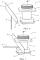
figures 6, 7 ,8 et 9 sont des vues schématiques en perspectives de quatre étapes d'assemblage du dispositif de chauffage sur le support de lentilles du dispositif optique selon l'invention. - Afin de faciliter la description, et de façon non limitative, un repère orthogonal comprenant un axe longitudinal L, un axe transversal T et un axe vertical V est défini. Des orientations « bas », « haut », « dessus », « dessous », « inférieure » et « supérieure » sont définies selon la direction verticale. Des orientations « gauche », « droite » et « latérale » sont définies selon la direction transversale. Des orientations « avant » et « arrière » sont également définies selon la direction longitudinale.
- Selon la
figure 1 et lafigure 2 , un dispositif optique 10, plus particulièrement une caméra pour véhicule est représentée. Ce type de caméra est prévu pour être monté à l'extérieur du véhicule et donc subir les conditions extérieures au véhicule tel que le climat. - Selon la
figure 1 , le dispositif optique 10 comprend un boîtier de protection 12 comprenant une paroi 15 de forme globalement cylindrique s'étendant selon l'axe vertical V depuis son extrémité haute 18 jusqu'à son extrémité basse 20. L'extrémité basse 20 du boîtier de protection 12 est fermée par un fond de boîtier 26. Le fond de boîtier 26 comprend un corps de connecteur 28 s'étendant verticalement vers l'extérieur du boîtier de protection 12, le corps de connecteur 28 étant venu de matière avec le fond de boîtier 26. - Le dispositif optique 10 comprend un support de lentilles 14 s'étendant verticalement dans le boîtier de protection 12. Le support de lentilles 14 est une structure creuse ouverte formant une cavité 21 s'étendant depuis son extrémité haute 19 agencée en dehors du boîtier de protection 12 jusqu'à son extrémité basse 30 insérée dans le boîtier de protection 12. L'extrémité haute 19 du support de lentilles 14 comporte une lentille optique 22 alignée selon l'axe optique O du dispositif optique 10.
- Le support de lentilles 14 est maintenu en butée contre l'extrémité haute 18 du boîtier de protection 12. Le support de lentilles 14 comprend donc une plaque d'appui 16 agencée en butée contre l'extrémité haute 18 du boîtier de protection 12. Le support de lentilles 14 est fixé en appui contre l'extrémité haute 18 du boîtier de protection 12 par l'intermédiaire d'un premier joint adhésif 13 de sorte à fermer hermétiquement le boîtier de protection 12. La plaque d'appui 16 comprend une ouverture circulaire débouchant sur la cavité 21 du support de lentilles 14 et comportant une paroi supérieure 17 au boîtier de protection 12 s'étendant verticalement jusqu'à l'extrémité haute 19 du support de lentilles 14. La lentille optique 22 vient s'agencer contre la surface interne de la paroi supérieure 17 et est maintenue alignée selon l'axe optique O du dispositif optique 10 par un capot de maintien 24 fixé sur la paroi supérieure 17.
- Selon la
figure 2 , le support de lentilles 14 comprend la paroi supérieure 17 agencée par-dessus la plaque d'appui 16 et comprend une paroi inférieure 31 au boîtier de protection 12 s'étendant verticalement depuis la plaque d'appui 16 jusqu'à son extrémité basse 30. L'extrémité basse 30 forme une base de forme globalement parallélépipédique. - Le dispositif optique 10 comprend une première carte à circuit imprimé 32 rigide.
- La première carte à circuit imprimé 32 rigide est de forme globalement rectangulaire. La première carte à circuit imprimé 32 comprend sur sa face supérieure un circuit électronique de capture d'images 36 aligné avec la lentille optique 22 selon l'axe optique O du dispositif optique 10. La carte à circuit imprimé 32 est prévue pour être fixée sur l'extrémité basse 30 du support de lentilles 14 par l'intermédiaire d'un second joint adhésif 38, de sorte à fermer hermétiquement la cavité 21 du support de lentilles 14.
- Le dispositif optique 10 comprend une seconde carte à circuit imprimé 34 rigide.
- La seconde carte à circuit imprimé 34 comprend sur sa face inférieure des terminaux électriques 40 s'étendant verticalement et prévus pour être insérés dans le corps du connecteur 28. La seconde carte à circuit imprimé 34 est donc prévue pour être agencée en fond de boîtier 26 de sorte que ses terminaux électriques 40 puissent être insérés dans le corps du connecteur 28.
- La seconde carte à circuit imprimé 34 comporte des moyens de connexions électriques 42 avec la première carte à circuit imprimé 32. La seconde carte à circuit imprimé 34 peut comprendre des composants électroniques de traitements d'images reçues du circuit électronique de capture d'image 36.
- Le dispositif optique 10 comprend une bande chauffante 50 flexible. La bande chauffante 50 est configurée pour être agencée autour de la paroi inférieure 31 du support de lentilles 14. Selon le mode de réalisation représenté, et de façon non limitative, la paroi inférieure 31 du support de lentilles 14 est une paroi cylindrique annulaire. Plus particulièrement, la bande chauffante 50 est configurée pour être enroulée autour de la paroi inférieure 31 annulaire du support de lentilles 14 de sorte à être au contact de la paroi 31 annulaire tout autour de celle-ci. La bande chauffante 50 comprend également une interface de connexion électrique 52 prévue pour être reliée électriquement à l'une des deux cartes à circuit imprimé rigide 32, 34 du dispositif optique. De façon non limitative, selon ce mode de réalisation, l'interface de connexion électrique 52 est prévue pour être reliée électriquement à la première carte à circuit imprimé rigide 32 par le biais d'un connecteur électrique 63 agencé sur la face inférieure de la première carte à circuit imprimé 32. Ce choix permet de limiter la dimension, plus précisément la longueur, de l'interface de connexion électrique 52.
- Selon la
figure 3 , la bande chauffante 50 est agencée autour de la paroi inférieure 31 du support de lentilles 14. La bande chauffante 50 est agencée de sorte à recouvrir l'extrémité haute 23 de la paroi inférieure 31 du support de lentille 14 de sorte à être au plus proche de la paroi supérieure du support de lentilles 14 prévue pour recevoir la lentille optique 22. La bande chauffante 50 comprend des conducteurs électriques 62 configurés pour être parcourus par un courant électrique provenant de la première carte à circuit imprimé 32. - La bande chauffante 50 est une carte à circuit imprimé flexible reliée par l'interface de connexion électrique 52 à la première carte à circuit imprimé 32. L'interface de connexion électrique 52 peut être une languette de connexion venue de matière avec la bande chauffante 50. En d'autres termes, la bande chauffante 50 et l'interface de connexion électrique 52 associée, sont une seule et unique carte à circuit imprimé flexible , par exemple en forme de T , avant son assemblage sur la paroi inférieure 31 du support de lentilles 14. La portion représentant la base du `T' forme l'interface de connexion électrique 52 de la bande chauffante, la tête du 'T' formant la bande chauffante 50 flexible configurée pour être agencée autour de la paroi inférieure 31 du support de lentilles 14.
- Selon la présente invention, la bande chauffante 50, l'interface de connexion électrique 52 et la première carte à circuit imprimé 32 peuvent être une seule et unique carte à circuit imprimé de type carte à circuit imprimé flex-rigide, c'est à dire une unique carte à circuit imprimé comprenant une portion flexible comportant la bande chauffante 50 flexible et comportant la languette flexible formant l'interface de connexion électrique 52, la dite portion flexible étant en continuité du substrat de la partie principale rigide.
- Selon la
figure 4 , les deux extrémités longitudinales 54, 56 opposées de la bande chauffante sont fixées sur la paroi inférieure 31 du support de lentilles 14. Selon lafigure 4 , les deux extrémités longitudinales 54, 56 comportent chacune une bande d'adhésif 53, 55 de type adhésif sensible à la pression de sorte à être coller sur la paroi inférieure 31 du support de lentilles 14. - Selon la
figure 5 , d'autres moyens d'attache 58 de la bande chauffante 50 sont agencés sur les extrémités 54, 56 longitudinales de la bande chauffante 50. Les moyens d'attache 58 peuvent comprendre une portion élastique de sorte à s'ajuster au profil de la paroi 31 du support de lentilles, les moyen d'attache élastique permettant de comprimer la bande chauffante 50 contre la paroi inférieure 31 du support de lentilles 14. Alternativement, un collier de serrage peut également être inséré autour de la bande chauffante 50 afin de pincer la bande chauffante 50 entre le collier de serrage et la paroi inférieure 31 du support de lentilles 14. - Selon les
figures 6, 7 ,8 et 9 quatre étapes d'assemblage du dispositif optique 10 décrit au travers desfigures 1 à 5 sont illustrées. - Selon la
figure 6 , une première étape consiste à fournir la première carte à circuit imprimé 32 rigide comprenant le composant électronique de capture d'images 36 agencée sur le support de lentilles 14 et alignée selon l'axe optique O du dispositif 10. En complément à la fourniture du support de lentilles 14 pré-assemblé avec la première carte à circuit imprimé 32, cette première étape comprend la fourniture de la bande chauffante 50 flexible comportant l'interface de connexion électrique 52 et également les moyens d'attache 58, notamment les deux bandes adhésives 53, 55 agencées chacune sur une extrémité longitudinale 54, 56 de la bande chauffante. Il est à noter que la bande chauffante 50 est présentée face au support de lentilles 14 de manière plane, donc non courbée. - Selon la
figure 7 , une seconde étape consiste à plaquer la bande chauffante 50 flexible en configuration plane contre la paroi inférieure 31 du support de lentilles 14. Plus particulièrement, une des deux extrémités verticales de la bande chauffante 50 est agencée au plus près, voir au contact, de la plaque d'appui 16 du support de lentilles 14. - Selon la
figure 8 , une troisième étape consiste à agencer la bande chauffante 50 tout autour et au contact de la paroi inférieure 31 du support de lentilles 14. Cette étape est complétée par une action de maintien de la bande chauffante 50 contre la paroi inférieure 31 du support de lentilles 14 par le biais des moyens d'attache 58 de la bande chauffante 50. Plus particulièrement une pression spécifique exercée sur les extrémités longitudinales 54, 56 permet l'adhésion des deux bandes adhésives 53, 55 sur la paroi inférieure 31 du support de lentilles 14. - Enfin, selon la
figure 9 , une étape de raccordement de l'interface de connexion électrique 52 à la première carte à circuit imprimé est effectuée par insertion de l'interface de connexion électrique 52, c'est-à-dire de l'extrémité libre de la languette de connexion électrique, dans le connecteur électrique 63 agencé sur la face inférieure de la première carte à circuit imprimé 32 rigide. - Selon la présente invention, l'étape de la fourniture de la carte à circuit imprimé 32 rigide, l'étape de la fourniture de la bande chauffante 50 et l'étape de raccordement électrique de l'interface de connexion électrique 52 à la première carte à circuit imprimé 32 rigide sont substituées par une étape unique de fourniture d'une seule carte à circuit imprimé comprenant une carte à circuit imprimé principale rigide comportant le composant électronique de capture d'images 36, et comprenant une carte à circuit imprimé flexible comportant la bande chauffante 50 flexible et comportant une extension formant l'interface de connexion électrique 52, la dite carte à circuit imprimé flexible étant en continuité du substrat de la partie principale rigide.
Claims (8)
- Dispositif optique (10) comprenantau moins une carte à circuit imprimé (32) rigide, la dite carte à circuit imprimé (32) comportant un circuit électronique de capture d'image (36);un support de lentilles (14) comprenant au moins une lentille optique (22), le support de lentilles (14) comprenant une paroi (31) formant une cavité (21) s'étendant selon l'axe optique (O) du dispositif (10) depuis son extrémité haute (19) jusqu'à son extrémité basse (30), l'extrémité basse (30) étant montée sur la carte à circuit imprimé (32) rigide de sorte à aligner, selon l'axe optique (O) du dispositif (10), le circuit électronique de capture d'images (36) et la lentille optique (22); etune bande chauffante (50) flexible agencée au contact de la paroi (31) du support de lentilles (14) et autour de la paroi (31) du support de lentilles (14), et comprenant une interface de connexion électrique (52) reliée électriquement à ladite carte à circuit imprimé (32) rigide du dispositif optique (10) ;caractérisé en ce queladite carte à circuit imprimé (32), ladite bande chauffante (50) et ladite interface de connexion électrique (52) sont une unique carte à circuit imprimé comportant une portion principale rigide comprenant ladite carte à circuit imprimé rigide (32) et une portion flexible comprenant la bande chauffante flexible (50) et une extension formant l'interface de connexion électrique (52), ladite portion flexible étant en continuité de substrat de la partie principale rigide, etles deux extrémités longitudinales (54, 56) de la bande chauffante (50) comprennent des moyens d'attache (58) qui serrent la bande chauffante (50) contre la paroi (31) du support de lentilles (14).
- Dispositif optique (10) selon la revendication 1 caractérisé en ce que l'interface de connexion électrique (52) est reliée électriquement à la carte à circuit imprimé (32) rigide comportant le circuit électronique de capture d'image (36).
- Dispositif optique (10) selon l'une quelconque des revendications précédentes caractérisé en ce que les moyens d'attache (58) comprennent une portion élastique de sorte à s'ajuster au profil de la paroi (31) du support de lentilles (14).
- Dispositif optique (10) selon l'une quelconque des revendications précédentes caractérisé en ce que la bande chauffante (50) comprend des conducteurs électriques (62) configurés pour être parcourus par un courant électrique provenant de la carte à circuit imprimé (32, 34).
- Dispositif optique (10) selon l'une quelconque des revendications précédentes caractérisé en ce que la bande chauffante (50) est formée par une carte à circuit imprimé de type flexible.
- Dispositif optique (10) selon la revendication précédente caractérisé ce que l'interface de connexion électrique (52) est une connexion de type carte à circuit imprimé flexible en continuité de substrat avec la bande chauffante (50).
- Dispositif optique (10) selon l'une quelconque des revendications précédentes caractérisé ce que l'interface de connexion électrique (52) comprend une partie amincie du substrat de la carte à circuit imprimé (32, 34) rigide.
- Méthode d'assemblage d'un dispositif optique (10) selon l'une quelconque des revendications précédentes, caractérisé en ce qu'elle comporte les étapes suivantes :fourniture d'un support de lentilles (14) comportant au moins une lentille optique (22) et comprenant une paroi (31) formant une cavité (21) s'étendant selon l'axe optique du dispositif (O);fourniture d'une carte à circuit imprimé (32) rigide comprenant un composant électronique de capture d'images (36);agencement de la carte à circuit imprimé (32) rigide sur le support de lentilles (14) de sorte à pouvoir aligner, selon l'axe optique (O) du dispositif (10), le circuit électronique de capture d'images (36) et la lentille optique (22);fourniture d'une bande chauffante (50) flexible comportant une interface de connexion électrique (52) et des moyens d'attache (58);raccordement électrique de l'interface de connexion électrique (52) à une carte à circuit imprimé (32) rigide du dispositif optique (10).agencement de la bande chauffante (50) autour de la paroi (31) du support de lentilles (14) ;maintien de la bande chauffante contre la paroi du support de lentilles (14) par le biais de moyens d'attache (58) agencés aux deux extrémités longitudinales (54, 56) de la bande chauffante (50), qui serrent la bande chauffante (50) contre la paroi (31) du support de lentilles (14) ;dans lequel l'étape de la fourniture de la carte à circuit imprimé (32) rigide, l'étape de la fourniture de la bande chauffante (50) et l'étape de raccordement électrique de l'interface de connexion électrique (52) à la carte à circuit imprimé (32) rigide sont mises en oeuvre par une étape unique de fourniture d'une seule carte à circuit imprimé comprenant une carte à circuit imprimé principale rigide comportant le composant électronique de capture d'images (36), et comprenant une carte à circuit imprimé flexible comportant la bande chauffante (50) flexible et comportant une extension formant l'interface de connexion électrique (52), la dite carte à circuit imprimé flexible étant en continuité du substrat de la partie principale rigide.
Applications Claiming Priority (1)
| Application Number | Priority Date | Filing Date | Title |
|---|---|---|---|
| FR1855337A FR3082634B1 (fr) | 2018-06-18 | 2018-06-18 | Dispositif optique pour vehicule comprenant un element de chauffage |
Publications (2)
| Publication Number | Publication Date |
|---|---|
| EP3584633A1 EP3584633A1 (fr) | 2019-12-25 |
| EP3584633B1 true EP3584633B1 (fr) | 2024-09-11 |
Family
ID=63312111
Family Applications (1)
| Application Number | Title | Priority Date | Filing Date |
|---|---|---|---|
| EP19181023.3A Active EP3584633B1 (fr) | 2018-06-18 | 2019-06-18 | Dispositif optique pour vehicule comprenant un element de chauffage |
Country Status (4)
| Country | Link |
|---|---|
| US (1) | US11653078B2 (fr) |
| EP (1) | EP3584633B1 (fr) |
| CN (1) | CN110618514A (fr) |
| FR (1) | FR3082634B1 (fr) |
Cited By (1)
| Publication number | Priority date | Publication date | Assignee | Title |
|---|---|---|---|---|
| DE102024122835A1 (de) * | 2024-08-09 | 2026-02-12 | Connaught Electronics Ltd. | Beheizen eines Linsenmoduls einer Kamera für ein Kraftfahrzeug |
Families Citing this family (15)
| Publication number | Priority date | Publication date | Assignee | Title |
|---|---|---|---|---|
| FR3082633B1 (fr) | 2018-06-18 | 2021-10-01 | Delphi Tech Llc | Dispositif optique pour vehicule comprenant un element de chauffage |
| FR3082634B1 (fr) | 2018-06-18 | 2021-10-01 | Delphi Tech Llc | Dispositif optique pour vehicule comprenant un element de chauffage |
| US12386142B2 (en) * | 2019-05-31 | 2025-08-12 | Lg Innotek Co., Ltd. | Camera module |
| US10881028B1 (en) * | 2019-07-03 | 2020-12-29 | Apple Inc. | Efficient heat removal from electronic modules |
| US11710945B2 (en) | 2020-05-25 | 2023-07-25 | Apple Inc. | Projection of patterned and flood illumination |
| CN113905472B (zh) * | 2020-07-07 | 2024-04-12 | 宁波舜宇车载光学技术有限公司 | 具有加热装置的镜片以及包括该镜片的镜头 |
| US11474417B2 (en) * | 2020-08-07 | 2022-10-18 | Lineage Logistics, LLC | Lens heater assembly for camera |
| US11630377B2 (en) * | 2020-08-11 | 2023-04-18 | Zf Friedrichshafen Ag | Lens assembly |
| US11699715B1 (en) | 2020-09-06 | 2023-07-11 | Apple Inc. | Flip-chip mounting of optoelectronic chips |
| DE102020212251A1 (de) * | 2020-09-29 | 2022-03-31 | Robert Bosch Gesellschaft mit beschränkter Haftung | Imagermodul für eine Kamera oder einen Sensor |
| JP7655801B2 (ja) * | 2021-06-30 | 2025-04-02 | ニデックインスツルメンツ株式会社 | レンズユニット |
| US20230011812A1 (en) * | 2021-07-06 | 2023-01-12 | Eterge Opto-Electronics Co., Ltd. | Optical imaging lens |
| DE102021123051A1 (de) | 2021-09-07 | 2023-03-09 | Connaught Electronics Ltd. | Beheizung eines Linsenmoduls einer Kamera für ein Kraftfahrzeug |
| US12313812B2 (en) | 2022-09-20 | 2025-05-27 | Apple Inc. | MOE-based illumination projector |
| US12123589B1 (en) | 2023-05-22 | 2024-10-22 | Apple Inc. | Flood projector with microlens array |
Citations (1)
| Publication number | Priority date | Publication date | Assignee | Title |
|---|---|---|---|---|
| KR101064666B1 (ko) * | 2011-05-31 | 2011-09-15 | (주)일산정밀 | 카메라용 히팅 윈도우 어셈블리 |
Family Cites Families (28)
| Publication number | Priority date | Publication date | Assignee | Title |
|---|---|---|---|---|
| AU2003290791A1 (en) * | 2002-11-14 | 2004-06-15 | Donnelly Corporation | Imaging system for vehicle |
| JP3905844B2 (ja) * | 2003-01-07 | 2007-04-18 | ペンタックス株式会社 | レンズの熱かしめ構造、熱かしめ方法及び熱かしめ工具 |
| KR101141722B1 (ko) * | 2007-05-30 | 2012-05-04 | 삼성테크윈 주식회사 | 보이스 코일 모듈 |
| TWM408051U (en) * | 2011-01-04 | 2011-07-21 | Topview Optronics Corp | Defogging and defrosting device for camera protection lens |
| US9235023B2 (en) | 2011-06-10 | 2016-01-12 | Flir Systems, Inc. | Variable lens sleeve spacer |
| CN104995906B (zh) | 2013-04-26 | 2018-01-26 | 株式会社村田制作所 | 摄像头模块的制造方法 |
| US9549470B2 (en) * | 2013-09-27 | 2017-01-17 | Exfo Inc. | Transceiver module adapter device |
| EP3163864B1 (fr) | 2014-06-26 | 2019-11-06 | Kyocera Corporation | Dispositif de capture d'image et véhicule |
| KR102293357B1 (ko) * | 2015-01-12 | 2021-08-25 | 엘지이노텍 주식회사 | 카메라 모듈 |
| US20160283864A1 (en) | 2015-03-27 | 2016-09-29 | Qualcomm Incorporated | Sequential image sampling and storage of fine-tuned features |
| US10609262B2 (en) * | 2015-06-03 | 2020-03-31 | Lg Innotek Co., Ltd. | Lens barrel and camera module comprising same |
| US10064270B2 (en) * | 2015-06-05 | 2018-08-28 | North Carolina State University | Flexible interconnects, systems, and uses thereof |
| WO2016200126A1 (fr) | 2015-06-08 | 2016-12-15 | 엘지이노텍(주) | Module d'appareil photographique |
| KR101957794B1 (ko) | 2015-10-05 | 2019-03-13 | 엘지전자 주식회사 | 카메라 모듈 및 카메라 모듈의 결로방지 시스템 |
| DE102016001048B4 (de) * | 2016-01-30 | 2024-02-29 | Schölly Fiberoptic GmbH | Endoskop |
| JP2017220308A (ja) * | 2016-06-03 | 2017-12-14 | 株式会社東海理化電機製作所 | 発熱体 |
| FR3054684B1 (fr) | 2016-07-29 | 2018-08-24 | Institut Vedecom | Systeme de pilotage d’un vehicule autonome |
| JP2018045132A (ja) * | 2016-09-15 | 2018-03-22 | 株式会社東海理化電機製作所 | 撮像装置 |
| US11420238B2 (en) | 2017-02-27 | 2022-08-23 | Texas Instruments Incorporated | Transducer-induced heating-facilitated cleaning |
| CN106973202B (zh) * | 2017-04-21 | 2020-03-13 | 信利光电股份有限公司 | 一种摄像模组及除霜方法 |
| CN207216107U (zh) * | 2017-04-26 | 2018-04-10 | 惠州市德赛西威汽车电子股份有限公司 | 一种用于解决高清摄像头镜头热补偿的结构装置 |
| FR3067131B1 (fr) | 2017-06-01 | 2019-06-21 | Aptiv Technologies Limited | Dispositif optique pour vehicule comprenant un element de chauffage |
| CN107333045B (zh) | 2017-08-09 | 2019-09-10 | 重庆万建电子工程有限责任公司 | 一种防雾摄像机 |
| CN207039747U (zh) | 2017-08-17 | 2018-02-23 | 厦门纵目实业有限公司 | 一种利于散热的车载摄像头 |
| CN207184639U (zh) | 2017-08-18 | 2018-04-03 | 成都金三立视频科技有限公司 | 一种防雾防水的枪形摄像机 |
| CN207438964U (zh) | 2017-08-23 | 2018-06-01 | 刘建兰 | 一种运用于冰箱内部玻璃片除雾的摄像头 |
| FR3082634B1 (fr) | 2018-06-18 | 2021-10-01 | Delphi Tech Llc | Dispositif optique pour vehicule comprenant un element de chauffage |
| FR3082633B1 (fr) | 2018-06-18 | 2021-10-01 | Delphi Tech Llc | Dispositif optique pour vehicule comprenant un element de chauffage |
-
2018
- 2018-06-18 FR FR1855337A patent/FR3082634B1/fr active Active
-
2019
- 2019-06-17 US US16/442,623 patent/US11653078B2/en active Active
- 2019-06-17 CN CN201910521544.5A patent/CN110618514A/zh active Pending
- 2019-06-18 EP EP19181023.3A patent/EP3584633B1/fr active Active
Patent Citations (1)
| Publication number | Priority date | Publication date | Assignee | Title |
|---|---|---|---|---|
| KR101064666B1 (ko) * | 2011-05-31 | 2011-09-15 | (주)일산정밀 | 카메라용 히팅 윈도우 어셈블리 |
Cited By (1)
| Publication number | Priority date | Publication date | Assignee | Title |
|---|---|---|---|---|
| DE102024122835A1 (de) * | 2024-08-09 | 2026-02-12 | Connaught Electronics Ltd. | Beheizen eines Linsenmoduls einer Kamera für ein Kraftfahrzeug |
Also Published As
| Publication number | Publication date |
|---|---|
| FR3082634A1 (fr) | 2019-12-20 |
| EP3584633A1 (fr) | 2019-12-25 |
| CN110618514A (zh) | 2019-12-27 |
| US20190381939A1 (en) | 2019-12-19 |
| US11653078B2 (en) | 2023-05-16 |
| FR3082634B1 (fr) | 2021-10-01 |
Similar Documents
| Publication | Publication Date | Title |
|---|---|---|
| EP3584633B1 (fr) | Dispositif optique pour vehicule comprenant un element de chauffage | |
| EP3547001B1 (fr) | Dispositif optique pour vehicule comprenant un element de chauffage | |
| EP3415369B1 (fr) | Ensemble de boîtier électronique, raccordement électrique et méthode d' assemblage | |
| EP3410199B1 (fr) | Dispositif optique pour vehicule comprenant un element de chauffage | |
| EP3584620B1 (fr) | Dispositif optique pour vehicule comprenant un element de chauffage | |
| EP3871296B1 (fr) | Dispositif de connexion pour véhicule équipé d'un capteur de température | |
| EP3672384A1 (fr) | Ensemble electrique d'une barre de connexion electrique et d'un module de refroidissement | |
| EP3328059B1 (fr) | Dispositif de camera d'un vehicule automobile et methode d'assemblage | |
| EP3840557A1 (fr) | Equipement electrique comprenant une barre de connexion electrique refroidie par deux faces d'un dissipateur thermique | |
| EP2745661B1 (fr) | Dispositif de connexion electrique, ensemble comprenant un tel dispositif et une carte electronique et procede de connexion electrique d'une carte electronique | |
| EP1912261A1 (fr) | Dispositif de raccordement électrique notamment pour panneau solaire électrique | |
| FR3148872A1 (fr) | Connecteur | |
| FR3067130B1 (fr) | Dispositif optique pour vehicule | |
| EP3476665A1 (fr) | Barre d'isolation éléctrique, notamment pour un module éléctronique de puissance d'un onduleur | |
| WO2013053476A2 (fr) | Systeme de maintien mecanique, ensemble comprenant un tel systeme et une carte electronique et procede d'assemblage sur une surface d'un tel systeme et d'une telle carte | |
| FR3126588A1 (fr) | Module electronique de commande pour radiateur electrique d’un vehicule automobile | |
| EP4034396B1 (fr) | Boitier d'interface électronique de commande d'un dispositif de chauffage électrique | |
| WO2020065170A1 (fr) | Boitier d'interface électronique d'un dispositif de chauffage électrique | |
| FR2928784A1 (fr) | Dispositif de raccordement electrique notamment pour panneau solaire electrique | |
| FR3139772A1 (fr) | Bloc optique pour véhicule automobile doté de moyens de connexion électrique simplifiés | |
| EP4555831A1 (fr) | Dispositif de chauffage électrique pour véhicule automobile | |
| FR3093397A1 (fr) | Boitier de module électronique avec organe de de dissipation thermique. | |
| WO2020065169A1 (fr) | Dispositif de chauffage electrique | |
| EP4615725A1 (fr) | Attache coulissante pour barres omnibus d'un système de batteries de véhicule électrique et véhicule comportant une telle attache | |
| FR3144705A1 (fr) | Module de batterie, notamment pour véhicule électrique et batterie comprenant un tel module ou une pluralité de tels modules |
Legal Events
| Date | Code | Title | Description |
|---|---|---|---|
| PUAI | Public reference made under article 153(3) epc to a published international application that has entered the european phase |
Free format text: ORIGINAL CODE: 0009012 |
|
| STAA | Information on the status of an ep patent application or granted ep patent |
Free format text: STATUS: THE APPLICATION HAS BEEN PUBLISHED |
|
| AK | Designated contracting states |
Kind code of ref document: A1 Designated state(s): AL AT BE BG CH CY CZ DE DK EE ES FI FR GB GR HR HU IE IS IT LI LT LU LV MC MK MT NL NO PL PT RO RS SE SI SK SM TR |
|
| AX | Request for extension of the european patent |
Extension state: BA ME |
|
| STAA | Information on the status of an ep patent application or granted ep patent |
Free format text: STATUS: REQUEST FOR EXAMINATION WAS MADE |
|
| 17P | Request for examination filed |
Effective date: 20200625 |
|
| RBV | Designated contracting states (corrected) |
Designated state(s): AL AT BE BG CH CY CZ DE DK EE ES FI FR GB GR HR HU IE IS IT LI LT LU LV MC MK MT NL NO PL PT RO RS SE SI SK SM TR |
|
| STAA | Information on the status of an ep patent application or granted ep patent |
Free format text: STATUS: EXAMINATION IS IN PROGRESS |
|
| 17Q | First examination report despatched |
Effective date: 20220314 |
|
| RAP3 | Party data changed (applicant data changed or rights of an application transferred) |
Owner name: APTIV TECHNOLOGIES LIMITED |
|
| GRAP | Despatch of communication of intention to grant a patent |
Free format text: ORIGINAL CODE: EPIDOSNIGR1 |
|
| STAA | Information on the status of an ep patent application or granted ep patent |
Free format text: STATUS: GRANT OF PATENT IS INTENDED |
|
| RIC1 | Information provided on ipc code assigned before grant |
Ipc: H04N 23/55 20230101ALI20231120BHEP Ipc: H04N 23/54 20230101ALI20231120BHEP Ipc: H04N 23/52 20230101ALI20231120BHEP Ipc: G03B 17/55 20060101AFI20231120BHEP |
|
| INTG | Intention to grant announced |
Effective date: 20231218 |
|
| RIN1 | Information on inventor provided before grant (corrected) |
Inventor name: POREDA, WITOLD Inventor name: RAFALOWSKI, ARKADIUSZ |
|
| RAP1 | Party data changed (applicant data changed or rights of an application transferred) |
Owner name: APTIV TECHNOLOGIES AG |
|
| GRAS | Grant fee paid |
Free format text: ORIGINAL CODE: EPIDOSNIGR3 |
|
| GRAA | (expected) grant |
Free format text: ORIGINAL CODE: 0009210 |
|
| STAA | Information on the status of an ep patent application or granted ep patent |
Free format text: STATUS: THE PATENT HAS BEEN GRANTED |
|
| AK | Designated contracting states |
Kind code of ref document: B1 Designated state(s): AL AT BE BG CH CY CZ DE DK EE ES FI FR GB GR HR HU IE IS IT LI LT LU LV MC MK MT NL NO PL PT RO RS SE SI SK SM TR |
|
| REG | Reference to a national code |
Ref country code: GB Ref legal event code: FG4D Free format text: NOT ENGLISH |
|
| REG | Reference to a national code |
Ref country code: CH Ref legal event code: EP |
|
| P01 | Opt-out of the competence of the unified patent court (upc) registered |
Free format text: CASE NUMBER: APP_47755/2024 Effective date: 20240820 |
|
| RAP4 | Party data changed (patent owner data changed or rights of a patent transferred) |
Owner name: APTIV TECHNOLOGIES AG |
|
| REG | Reference to a national code |
Ref country code: DE Ref legal event code: R096 Ref document number: 602019058600 Country of ref document: DE |
|
| REG | Reference to a national code |
Ref country code: IE Ref legal event code: FG4D Free format text: LANGUAGE OF EP DOCUMENT: FRENCH |
|
| REG | Reference to a national code |
Ref country code: LT Ref legal event code: MG9D |
|
| PG25 | Lapsed in a contracting state [announced via postgrant information from national office to epo] |
Ref country code: NO Free format text: LAPSE BECAUSE OF FAILURE TO SUBMIT A TRANSLATION OF THE DESCRIPTION OR TO PAY THE FEE WITHIN THE PRESCRIBED TIME-LIMIT Effective date: 20241211 |
|
| REG | Reference to a national code |
Ref country code: NL Ref legal event code: MP Effective date: 20240911 |
|
| PG25 | Lapsed in a contracting state [announced via postgrant information from national office to epo] |
Ref country code: GR Free format text: LAPSE BECAUSE OF FAILURE TO SUBMIT A TRANSLATION OF THE DESCRIPTION OR TO PAY THE FEE WITHIN THE PRESCRIBED TIME-LIMIT Effective date: 20241212 Ref country code: FI Free format text: LAPSE BECAUSE OF FAILURE TO SUBMIT A TRANSLATION OF THE DESCRIPTION OR TO PAY THE FEE WITHIN THE PRESCRIBED TIME-LIMIT Effective date: 20240911 |
|
| PG25 | Lapsed in a contracting state [announced via postgrant information from national office to epo] |
Ref country code: BG Free format text: LAPSE BECAUSE OF FAILURE TO SUBMIT A TRANSLATION OF THE DESCRIPTION OR TO PAY THE FEE WITHIN THE PRESCRIBED TIME-LIMIT Effective date: 20240911 |
|
| PG25 | Lapsed in a contracting state [announced via postgrant information from national office to epo] |
Ref country code: LV Free format text: LAPSE BECAUSE OF FAILURE TO SUBMIT A TRANSLATION OF THE DESCRIPTION OR TO PAY THE FEE WITHIN THE PRESCRIBED TIME-LIMIT Effective date: 20240911 |
|
| PG25 | Lapsed in a contracting state [announced via postgrant information from national office to epo] |
Ref country code: HR Free format text: LAPSE BECAUSE OF FAILURE TO SUBMIT A TRANSLATION OF THE DESCRIPTION OR TO PAY THE FEE WITHIN THE PRESCRIBED TIME-LIMIT Effective date: 20240911 |
|
| PG25 | Lapsed in a contracting state [announced via postgrant information from national office to epo] |
Ref country code: RS Free format text: LAPSE BECAUSE OF FAILURE TO SUBMIT A TRANSLATION OF THE DESCRIPTION OR TO PAY THE FEE WITHIN THE PRESCRIBED TIME-LIMIT Effective date: 20241211 Ref country code: ES Free format text: LAPSE BECAUSE OF FAILURE TO SUBMIT A TRANSLATION OF THE DESCRIPTION OR TO PAY THE FEE WITHIN THE PRESCRIBED TIME-LIMIT Effective date: 20240911 |
|
| PG25 | Lapsed in a contracting state [announced via postgrant information from national office to epo] |
Ref country code: RS Free format text: LAPSE BECAUSE OF FAILURE TO SUBMIT A TRANSLATION OF THE DESCRIPTION OR TO PAY THE FEE WITHIN THE PRESCRIBED TIME-LIMIT Effective date: 20241211 Ref country code: NO Free format text: LAPSE BECAUSE OF FAILURE TO SUBMIT A TRANSLATION OF THE DESCRIPTION OR TO PAY THE FEE WITHIN THE PRESCRIBED TIME-LIMIT Effective date: 20241211 Ref country code: LV Free format text: LAPSE BECAUSE OF FAILURE TO SUBMIT A TRANSLATION OF THE DESCRIPTION OR TO PAY THE FEE WITHIN THE PRESCRIBED TIME-LIMIT Effective date: 20240911 Ref country code: HR Free format text: LAPSE BECAUSE OF FAILURE TO SUBMIT A TRANSLATION OF THE DESCRIPTION OR TO PAY THE FEE WITHIN THE PRESCRIBED TIME-LIMIT Effective date: 20240911 Ref country code: GR Free format text: LAPSE BECAUSE OF FAILURE TO SUBMIT A TRANSLATION OF THE DESCRIPTION OR TO PAY THE FEE WITHIN THE PRESCRIBED TIME-LIMIT Effective date: 20241212 Ref country code: FI Free format text: LAPSE BECAUSE OF FAILURE TO SUBMIT A TRANSLATION OF THE DESCRIPTION OR TO PAY THE FEE WITHIN THE PRESCRIBED TIME-LIMIT Effective date: 20240911 Ref country code: ES Free format text: LAPSE BECAUSE OF FAILURE TO SUBMIT A TRANSLATION OF THE DESCRIPTION OR TO PAY THE FEE WITHIN THE PRESCRIBED TIME-LIMIT Effective date: 20240911 Ref country code: BG Free format text: LAPSE BECAUSE OF FAILURE TO SUBMIT A TRANSLATION OF THE DESCRIPTION OR TO PAY THE FEE WITHIN THE PRESCRIBED TIME-LIMIT Effective date: 20240911 |
|
| REG | Reference to a national code |
Ref country code: AT Ref legal event code: MK05 Ref document number: 1723209 Country of ref document: AT Kind code of ref document: T Effective date: 20240911 |
|
| PG25 | Lapsed in a contracting state [announced via postgrant information from national office to epo] |
Ref country code: NL Free format text: LAPSE BECAUSE OF FAILURE TO SUBMIT A TRANSLATION OF THE DESCRIPTION OR TO PAY THE FEE WITHIN THE PRESCRIBED TIME-LIMIT Effective date: 20240911 |
|
| PG25 | Lapsed in a contracting state [announced via postgrant information from national office to epo] |
Ref country code: IS Free format text: LAPSE BECAUSE OF FAILURE TO SUBMIT A TRANSLATION OF THE DESCRIPTION OR TO PAY THE FEE WITHIN THE PRESCRIBED TIME-LIMIT Effective date: 20250111 Ref country code: PT Free format text: LAPSE BECAUSE OF FAILURE TO SUBMIT A TRANSLATION OF THE DESCRIPTION OR TO PAY THE FEE WITHIN THE PRESCRIBED TIME-LIMIT Effective date: 20250113 |
|
| PG25 | Lapsed in a contracting state [announced via postgrant information from national office to epo] |
Ref country code: RO Free format text: LAPSE BECAUSE OF FAILURE TO SUBMIT A TRANSLATION OF THE DESCRIPTION OR TO PAY THE FEE WITHIN THE PRESCRIBED TIME-LIMIT Effective date: 20240911 Ref country code: SM Free format text: LAPSE BECAUSE OF FAILURE TO SUBMIT A TRANSLATION OF THE DESCRIPTION OR TO PAY THE FEE WITHIN THE PRESCRIBED TIME-LIMIT Effective date: 20240911 |
|
| PG25 | Lapsed in a contracting state [announced via postgrant information from national office to epo] |
Ref country code: EE Free format text: LAPSE BECAUSE OF FAILURE TO SUBMIT A TRANSLATION OF THE DESCRIPTION OR TO PAY THE FEE WITHIN THE PRESCRIBED TIME-LIMIT Effective date: 20240911 Ref country code: AT Free format text: LAPSE BECAUSE OF FAILURE TO SUBMIT A TRANSLATION OF THE DESCRIPTION OR TO PAY THE FEE WITHIN THE PRESCRIBED TIME-LIMIT Effective date: 20240911 |
|
| PG25 | Lapsed in a contracting state [announced via postgrant information from national office to epo] |
Ref country code: CZ Free format text: LAPSE BECAUSE OF FAILURE TO SUBMIT A TRANSLATION OF THE DESCRIPTION OR TO PAY THE FEE WITHIN THE PRESCRIBED TIME-LIMIT Effective date: 20240911 Ref country code: PL Free format text: LAPSE BECAUSE OF FAILURE TO SUBMIT A TRANSLATION OF THE DESCRIPTION OR TO PAY THE FEE WITHIN THE PRESCRIBED TIME-LIMIT Effective date: 20240911 |
|
| PG25 | Lapsed in a contracting state [announced via postgrant information from national office to epo] |
Ref country code: SK Free format text: LAPSE BECAUSE OF FAILURE TO SUBMIT A TRANSLATION OF THE DESCRIPTION OR TO PAY THE FEE WITHIN THE PRESCRIBED TIME-LIMIT Effective date: 20240911 Ref country code: IT Free format text: LAPSE BECAUSE OF FAILURE TO SUBMIT A TRANSLATION OF THE DESCRIPTION OR TO PAY THE FEE WITHIN THE PRESCRIBED TIME-LIMIT Effective date: 20240911 |
|
| REG | Reference to a national code |
Ref country code: DE Ref legal event code: R097 Ref document number: 602019058600 Country of ref document: DE |
|
| PGFP | Annual fee paid to national office [announced via postgrant information from national office to epo] |
Ref country code: DE Payment date: 20250519 Year of fee payment: 7 |
|
| PG25 | Lapsed in a contracting state [announced via postgrant information from national office to epo] |
Ref country code: DK Free format text: LAPSE BECAUSE OF FAILURE TO SUBMIT A TRANSLATION OF THE DESCRIPTION OR TO PAY THE FEE WITHIN THE PRESCRIBED TIME-LIMIT Effective date: 20240911 |
|
| PGFP | Annual fee paid to national office [announced via postgrant information from national office to epo] |
Ref country code: GB Payment date: 20250602 Year of fee payment: 7 |
|
| PGFP | Annual fee paid to national office [announced via postgrant information from national office to epo] |
Ref country code: FR Payment date: 20250611 Year of fee payment: 7 |
|
| PLBE | No opposition filed within time limit |
Free format text: ORIGINAL CODE: 0009261 |
|
| STAA | Information on the status of an ep patent application or granted ep patent |
Free format text: STATUS: NO OPPOSITION FILED WITHIN TIME LIMIT |
|
| 26N | No opposition filed |
Effective date: 20250612 |
|
| PG25 | Lapsed in a contracting state [announced via postgrant information from national office to epo] |
Ref country code: SE Free format text: LAPSE BECAUSE OF FAILURE TO SUBMIT A TRANSLATION OF THE DESCRIPTION OR TO PAY THE FEE WITHIN THE PRESCRIBED TIME-LIMIT Effective date: 20240911 |
|
| REG | Reference to a national code |
Ref country code: CH Ref legal event code: H13 Free format text: ST27 STATUS EVENT CODE: U-0-0-H10-H13 (AS PROVIDED BY THE NATIONAL OFFICE) Effective date: 20260127 |
|
| PG25 | Lapsed in a contracting state [announced via postgrant information from national office to epo] |
Ref country code: MC Free format text: LAPSE BECAUSE OF FAILURE TO SUBMIT A TRANSLATION OF THE DESCRIPTION OR TO PAY THE FEE WITHIN THE PRESCRIBED TIME-LIMIT Effective date: 20240911 |
|
| PG25 | Lapsed in a contracting state [announced via postgrant information from national office to epo] |
Ref country code: LU Free format text: LAPSE BECAUSE OF NON-PAYMENT OF DUE FEES Effective date: 20250618 |
|
| REG | Reference to a national code |
Ref country code: BE Ref legal event code: MM Effective date: 20250630 |
|
| PG25 | Lapsed in a contracting state [announced via postgrant information from national office to epo] |
Ref country code: IE Free format text: LAPSE BECAUSE OF NON-PAYMENT OF DUE FEES Effective date: 20250618 |
|
| PG25 | Lapsed in a contracting state [announced via postgrant information from national office to epo] |
Ref country code: BE Free format text: LAPSE BECAUSE OF NON-PAYMENT OF DUE FEES Effective date: 20250630 |
|
| PG25 | Lapsed in a contracting state [announced via postgrant information from national office to epo] |
Ref country code: CH Free format text: LAPSE BECAUSE OF NON-PAYMENT OF DUE FEES Effective date: 20250630 |