EP3584953A1 - Station de base sans fil, et procédé de communication sans fil - Google Patents
Station de base sans fil, et procédé de communication sans fil Download PDFInfo
- Publication number
- EP3584953A1 EP3584953A1 EP17896429.2A EP17896429A EP3584953A1 EP 3584953 A1 EP3584953 A1 EP 3584953A1 EP 17896429 A EP17896429 A EP 17896429A EP 3584953 A1 EP3584953 A1 EP 3584953A1
- Authority
- EP
- European Patent Office
- Prior art keywords
- radio base
- base station
- user terminal
- section
- precoding
- Prior art date
- Legal status (The legal status is an assumption and is not a legal conclusion. Google has not performed a legal analysis and makes no representation as to the accuracy of the status listed.)
- Pending
Links
Images





Classifications
-
- H—ELECTRICITY
- H04—ELECTRIC COMMUNICATION TECHNIQUE
- H04B—TRANSMISSION
- H04B7/00—Radio transmission systems, i.e. using radiation field
- H04B7/02—Diversity systems; Multi-antenna system, i.e. transmission or reception using multiple antennas
- H04B7/04—Diversity systems; Multi-antenna system, i.e. transmission or reception using multiple antennas using two or more spaced independent antennas
- H04B7/0413—MIMO systems
- H04B7/0452—Multi-user MIMO systems
-
- H—ELECTRICITY
- H04—ELECTRIC COMMUNICATION TECHNIQUE
- H04B—TRANSMISSION
- H04B7/00—Radio transmission systems, i.e. using radiation field
- H04B7/02—Diversity systems; Multi-antenna system, i.e. transmission or reception using multiple antennas
- H04B7/04—Diversity systems; Multi-antenna system, i.e. transmission or reception using multiple antennas using two or more spaced independent antennas
- H04B7/0413—MIMO systems
- H04B7/0456—Selection of precoding matrices or codebooks, e.g. using matrices antenna weighting
-
- H—ELECTRICITY
- H04—ELECTRIC COMMUNICATION TECHNIQUE
- H04B—TRANSMISSION
- H04B7/00—Radio transmission systems, i.e. using radiation field
- H04B7/02—Diversity systems; Multi-antenna system, i.e. transmission or reception using multiple antennas
- H04B7/022—Site diversity; Macro-diversity
- H04B7/024—Co-operative use of antennas of several sites, e.g. in co-ordinated multipoint or co-operative multiple-input multiple-output [MIMO] systems
-
- H—ELECTRICITY
- H04—ELECTRIC COMMUNICATION TECHNIQUE
- H04B—TRANSMISSION
- H04B7/00—Radio transmission systems, i.e. using radiation field
- H04B7/02—Diversity systems; Multi-antenna system, i.e. transmission or reception using multiple antennas
- H04B7/04—Diversity systems; Multi-antenna system, i.e. transmission or reception using multiple antennas using two or more spaced independent antennas
- H04B7/06—Diversity systems; Multi-antenna system, i.e. transmission or reception using multiple antennas using two or more spaced independent antennas at the transmitting station
- H04B7/0613—Diversity systems; Multi-antenna system, i.e. transmission or reception using multiple antennas using two or more spaced independent antennas at the transmitting station using simultaneous transmission
- H04B7/0615—Diversity systems; Multi-antenna system, i.e. transmission or reception using multiple antennas using two or more spaced independent antennas at the transmitting station using simultaneous transmission of weighted versions of same signal
- H04B7/0617—Diversity systems; Multi-antenna system, i.e. transmission or reception using multiple antennas using two or more spaced independent antennas at the transmitting station using simultaneous transmission of weighted versions of same signal for beam forming
-
- H—ELECTRICITY
- H04—ELECTRIC COMMUNICATION TECHNIQUE
- H04W—WIRELESS COMMUNICATION NETWORKS
- H04W72/00—Local resource management
- H04W72/04—Wireless resource allocation
- H04W72/044—Wireless resource allocation based on the type of the allocated resource
- H04W72/046—Wireless resource allocation based on the type of the allocated resource the resource being in the space domain, e.g. beams
-
- H—ELECTRICITY
- H04—ELECTRIC COMMUNICATION TECHNIQUE
- H04W—WIRELESS COMMUNICATION NETWORKS
- H04W76/00—Connection management
- H04W76/10—Connection setup
- H04W76/15—Setup of multiple wireless link connections
-
- H—ELECTRICITY
- H04—ELECTRIC COMMUNICATION TECHNIQUE
- H04W—WIRELESS COMMUNICATION NETWORKS
- H04W88/00—Devices specially adapted for wireless communication networks, e.g. terminals, base stations or access point devices
- H04W88/02—Terminal devices
- H04W88/06—Terminal devices adapted for operation in multiple networks or having at least two operational modes, e.g. multi-mode terminals
Definitions
- the present invention relates to a radio base station and a radio communication method.
- LTE Long Term Evolution
- LTE-A LTE-Advanced
- FRA Full Radio Access
- 5G 5th generation mobile communication system
- 5G+ 5G plus
- New-RAT Radio Access Technology
- Massive MIMO Multiple Input Multiple Output
- a high frequency band for example, 5 GHz or higher
- An example of a technique of controlling beams or streams in MIMO includes a method of combining digital precoding/postcoding (hereinafter, simply referred to as precoding/postcoding in some cases) and beam-forming (BF) (for example, see NPL 1).
- precoding/postcoding in some cases
- BF beam-forming
- NPL 1 T.Obara et al. "Joint Processing of Analog Fixed Beamforming and CSI-based Precoding for Super High Bit Rate Massive MIMO Transmission Using Higher Frequency Bands," IEICE Transactions on Communications VOL. E98-B, NO. 8 August 2015
- An aspect of the present invention provides a radio base station and a radio communication method that can appropriately control beams in the multi-site environment.
- An aspect of the present invention provides a radio base station in a radio communication system that performs MIMO transmission between a plurality of radio base stations and at least one user terminal, the radio base station including: a precoding section that applies precoding to a data signal based on channel information indicating channels between the radio base stations and the user terminal; and a communication section that transmits the precoded data signal, in which the precoding in a first radio base station of the plurality of radio base stations is applied based on the channel information including at least a channel between the first radio base station and a first user terminal connected to a second radio base station other than the first radio base station.
- the beams can be appropriately controlled in the multi-site environment.
- Streams are distributed and multiplexed for a plurality of user terminals in MU-MIMO (Multi-User MIMO) transmission in the case described below.
- MU-MIMO Multi-User MIMO
- BF and precoding/postcoding are performed in Massive MIMO in the case described below. Therefore, precoding/postcoding and beam-forming are performed in the MU-MIMO transmission between a radio base station and a plurality of user terminals in a radio communication system according to the present invention.
- the precoding will be sorted into precoding for inter-user interference (IUI) and precoding for inter-stream interference (ISI) in each user terminal.
- Precoding is performed for the inter-user interference, and precoding and postcoding are performed for the inter-stream interference in each user terminal.
- the radio base station includes N T antenna elements and performs Massive MIMO transmission in the downlink between the radio base station and N U user terminals.
- the number of streams is M i .
- reception signal r received by each user terminal is expressed by the following equation 1.
- W represents a BF weight
- P IUI represents a precoding matrix for the inter-user interference
- P ISI represents a precoding matrix for the inter-stream interference
- z represents noise.
- precoding processing (P IUI ) for the inter-user interference in the precoding orthogonalizes the channels between the user terminals and prevents the inter-user interference.
- precoding matrix P ISI and postcoding matrix B ISI orthogonalize the channels between the streams of the user terminals and prevent the inter-stream interference.
- precoding matrices P IUI , P ISI
- postcoding matrix B ISI
- precoding matrices P IUI , P ISI
- postcoding matrix B ISI
- SVD singular value decomposition
- the precoding processing and the beam-forming processing are processing for a plurality of user terminals connected to one radio base station. Therefore, the processing is processing in a site formed by a single Massive MIMO base station.
- beam control such as precoding processing and beam-forming processing, in sites (multiple sites) formed by a plurality of Massive MIMO base stations needs to be examined.
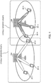
- FIG. 1 shows a configuration example of a radio communication system according to the present embodiment.
- the radio communication system includes a plurality of radio base stations 10 and at least one user terminal 20.
- the radio base station 10 is, for example, a Massive MIMO base station.
- Each user terminal 20 is connected to (accesses) at least one radio base station 10.
- user terminals 20-1 to 20-3 are connected to radio base station 10A
- user terminals 20-4 to 20-6 are connected to radio base station 10B.
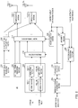
- FIG. 2 illustrates an example of an overall configuration of the radio base station according to the present embodiment.
- Radio base station 10 shown in FIG. 2 includes discovery signal generation section 101, candidate weight multiplication section 102, reference signal generation section 103, access point selection section 104, inter-base station communication section 105, weight selection section 106, judgement section 107, precoding matrix generation section 108, data generation section 109, precoding section 110, beam-forming section 111, communication sections 112, and antennas 113.
- constituent sections for example, IFFT processing section and CP adding section
- OFDM Orthogonal Frequency Division Multiplexing
- the signal waveform of the signal transmitted from radio base station 10 is not limited to the waveform based on OFDM modulation.
- Discovery signal generation section 101 generates discovery signals (reference signals) for deciding BF weight (W). For example, discovery signal generation section 101 generates at least the same number of discovery signals as the number of candidates of the BF weight. Discovery signal generation section 101 outputs the generated discovery signals to candidate weight multiplication section 102.
- Candidate weight multiplication section 102 multiplies the discovery signals input from discovery signal generation section 101 by the candidates of the BF weight, respectively, and outputs the discovery signals multiplied by the BF weight candidates to communication sections 112.
- Reference signal generation section 103 generates a reference signal used for channel estimation and outputs the reference signal to beam-forming section 111.
- Access point selection section 104 selects user terminal 20 to be connected to radio base station 10 among the plurality of radio base stations 10 based on candidate weight information fed back from each user terminal 20.
- candidate weight information include an SNR (Signal to Noise Ratio) of the discovery signal multiplied by the candidate weight and received power.
- access point selection section 104 selects radio base station 10 that generates the BF weight with the maximum candidate weight information (received power) and sets radio base station 10 as a radio base station as an access point of user terminal 20.
- Access point selection section 104 may, for example, notify user terminal 20 connected to radio base station 10 of access point information indicating radio base station 10 as an access point of user terminal 20 (not illustrated).
- Each user terminal 20 performs a connection operation for radio base station 10 indicated in the access point information.
- Access point selection section 104 may also, for example, notify other radio base stations 10 of the access point information indicating radio base station 10 as an access point of user terminal 20 through inter-base station communication section 105.
- access point selection section 104 may specify user terminal 20 to be connected to radio base station 10 based on the access point information reported from other radio base stations 10 through inter-base station communication section 105.
- Inter-base station communication section 105 communicates with other radio base stations 10 or a control station (may also be referred to as a central control station) that controls a plurality of radio base stations 10 through, for example, a backhaul.
- a control station may also be referred to as a central control station
- Weight selection section 106 selects BF weight (W) to be used for beam-forming from the BF weight candidates based on the candidate weight information fed back from each user terminal 20 and outputs BF weight (W) to beam-forming section 111. For example, weight selection section 106 may select L BF weights not overlapping with each other, in descending order of SNR (or received power) indicated in the candidate weight information.
- Judgement section 107 judges whether to execute extended precoding based on the candidate weight information fed back from each user terminal 20. For example, judgement section 107 specifies user terminals 20 other than user terminals 20 connected to radio base station 10 (that is, user terminals 20 not connected to radio base station 10) based on the access point information input from access point selection section 104. Judgement section 107 then judges to execute the extended precoding when there is user terminal 20 in which the SNR indicated in the candidate weight information is smaller than predetermined threshold ⁇ among user terminals 20 not connected to radio base station 10.
- judgement section 107 judges to execute normal precoding without executing the extended precoding when there is no user terminal 20 in which the SNR indicated in the candidate weight information is smaller than predetermined threshold ⁇ among user terminals 20 not connected to radio base station 10. Judgement section 107 outputs the judgement result to precoding matrix generation section 108.
- the normal precoding is precoding applied based on channel estimation values fed back from user terminals 20 connected to single radio base station 10.
- the extended precoding is precoding applied based on channel estimation values including channels between radio base station 10 and user terminals 20 connected to radio base station 10 and channels between radio base station 10 and user terminals 20 connected to radio base stations 10 other than radio base station 10, in which the SNR of user terminals 20 is smaller than predetermined threshold ⁇ .
- a precoding matrix generated in the normal precoding based on the channel estimation values indicating the channels between single radio base station 10 and user terminals 20 connected to radio base station 10 will be referred to as a "normal precoding matrix”.
- a precoding matrix generated in the extended precoding based on the channel estimation values including the channels between radio base station 10 and user terminals 20 connected to radio base station 10 and the channels between radio base station 10 and user terminals 20 connected to other radio base stations 10 will be referred to as an "extended precoding matrix".
- precoding matrix generation section 108 uses the channel estimation values fed back from user terminals 20 to generate the normal precoding matrix or the extended precoding matrix.
- the channel estimation value is, for example, channel information (HW) indicating the equivalent channel matrix including BF weight (W).
- precoding matrix generation section 108 generates precoding matrix (P IUI ) for removing the interference between a plurality of user terminals 20 (inter-user interference) multiplexed in the MU-MIMO and precoding matrix (P ISI ) for removing the interference between a plurality of streams (inter-stream interference) in each user terminal 20.
- Precoding matrix generation section 108 also generates an extended precoding matrix for removing interference of user terminals 20 that are interfered by radio base station 10 and that are connected to radio base stations other than radio base station 10.
- Precoding matrix generation section 108 outputs generated precoding matrices (P IUI , P ISI ) (hereinafter, collectively referred to as "P" in some cases) to precoding section 110.
- Data generation section 109 generates data (downlink signals) for a plurality of user terminals 20.
- FIG. 2 shows a configuration of data generation section 109 for one user terminal 20 (i-th user terminal 20).
- radio base station 10 includes data generation section 109 for each of a plurality of (Nu) user terminals 20.
- Data generation section 109 includes coding sections 191 and modulation sections 192. Coding sections 191 and modulation sections 192 are provided according to the number of streams (M i ) for user terminal i. Each coding section 191 encodes data signals of M i streams. Each modulation section 192 modulates the encoded data signals and outputs the modulated data signals to precoding section 110. Note that the code rate and the modulation scheme in each coding section 191 and each modulation section 192 may be different in each stream.
- Precoding section 110 multiplies the data signals input from data generation section 109 by precoding matrix (P) and outputs the precoded data signals to beam-forming section 111.
- precoding section 110 applies precoding to the data signals of M streams to generate L (the number of beams, for example, L>M) signals.
- each user terminal 20 can use the reference signal multiplied by BF weight (W) decided based on the candidate weight information (SNR) to estimate equivalent channel information (HW) including the BF weight.
- W BF weight
- SNR candidate weight information
- beam-forming section 111 multiplies the data signals input from precoding section 110 by BF weight (W) input from weight selection section 106 and outputs the data signals (N T signals) after the BF weight multiplication to communication section 112.
- Communication sections 112-1 to 112-N T are provided according to N T antennas 113 (antenna elements). Each communication section 112 applies transmission processing, such as D/A conversion and up-conversion, to the input signals. Each communication section 112 multiplexes the signals after the transmission processing based on, for example, time-division, frequency-division, or code-division multiplexing and transmits the signals from N T antennas 113, respectively. Specifically, each communication section 112 transmits the discovery signal input from candidate weight multiplication section 102 to each user terminal 20 through antenna 113. In the channel estimation, communication section 112 transmits the reference signal input from beam-forming section 111 to each user terminal 20 through antenna 113. At data transmission, communication section 112 transmits the signal of the stream input from beam-forming section 111 to each user terminal 20 through antenna 113.
- transmission processing such as D/A conversion and up-conversion
- FIG. 3 illustrates an example of an overall configuration of the user terminal according to the present embodiment.
- User terminal 20 shown in FIG. 3 includes antennas 201, communication sections 202, candidate weight information measurement section 203, channel estimation section 204, postcoding matrix generation section 205, postcoding section 206, and data reception section 207.
- FIG. 3 shows an example of the configuration of i-th user terminal 20.
- Constituent sections for example, CP removing section and FFT processing section
- the signal waveform of the signal received by user terminal 20 is not limited to the waveform based on the OFDM modulation.
- Communication sections 202-1 to 202-N Ri are provided according to N Ri antennas 201, respectively.
- Each communication section 202 applies reception processing, such as down-conversion and A/D conversion, to the reception signals received through antenna 201.
- the reception signals include the discovery signal, the reference signal, and the data signal.
- Communication section 202 outputs the discovery signal to candidate weight information measurement section 203, outputs the reference signal to channel estimation section 204, and outputs the data signal to postcoding section 206.
- Candidate weight information measurement section 203 uses the discovery signals input from communication sections 202 to measure the candidate weight information (for example, SNR or received power). The discovery signals are multiplied by the BF weight candidates, respectively. Therefore, candidate weight information measurement section 203 measures the SNR or the received power for each BF weight candidate used. The candidate weight information indicating the measured SNR or received power is fed back to radio base station 10 through, for example, communication section 202.
- the candidate weight information for example, SNR or received power.
- Channel estimation section 204 uses the reference signal input from communication section 202 to estimate the channel estimation value (channel information) indicating the channel between radio base station 10 and user terminal 20.
- the reference signal is multiplied by BF weight (W) in radio base station 10 (beam-forming section 111). Therefore, channel estimation section 204 estimates equivalent channel information including the BF weight (equivalent channel matrix HW).
- Estimated channel information (HW) is fed back to radio base station 10 (precoding matrix generation section 108) through, for example, communication section 202.
- Channel estimation section 204 also outputs the estimated channel information to postcoding matrix generation section 205.
- Postcoding matrix generation section 205 uses channel information (HW) input from channel estimation section 204 to generate postcoding matrix (B ISI ). Postcoding matrix generation section 205 outputs the generated postcoding matrix to postcoding section 206. Note that postcoding matrix generation section 205 may use channel information HWP estimated by using the reference signal multiplied by the precoding matrix (extended precoding matrix) and the BF weight to generate the postcoding matrix.
- HW channel information
- B ISI postcoding matrix
- Postcoding section 206 uses postcoding matrix (B ISI ) input from postcoding matrix generation section 205 to perform postcoding of the data signal input from communication section 202.
- Postcoding section 206 outputs the data signal after the postcoding to data reception section 207.
- B ISI postcoding matrix
- Data reception section 207 applies reception processing (including demodulation processing and decoding processing) to the data signal input from postcoding section 206 and obtains a plurality of streams for i-th user terminal 20.
- Data reception section 207 includes demodulation sections 271 and decoding sections 272.
- Demodulation sections 271 and decoding sections 272 are provided according to the number of streams (M i ) for i-th user terminal 20.
- Each demodulation section 271 demodulates the data signals of M i streams, and each decoding section 272 decodes the demodulated data signals to obtain M i streams. Note that the code rate and the modulation scheme in each demodulation section 271 and each decoding section 272 may be different in each stream.
- radio base station 10 Next, operation of radio base station 10 and user terminal 20 will be described in detail.
- the radio communication system includes AP radio base stations 10 and AP ⁇ N U user terminals 20.
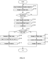
- FIG. 4 is a flow chart showing an operation of radio base station 10 according to the present embodiment.
- radio base station 10 selects one of the candidates for BF weight (W) (ST101). Radio base station 10 then transmits the discovery signal multiplied by the selected candidate for BF weight (W) to user terminal 20 (ST102). If radio base station 10 has not transmitted the discovery signals corresponding to all of the candidates for BF weight (W) (ST103: No), radio base station 10 returns to the processing of ST101 and ST102 and transmits the discovery signal multiplied by another candidate for BF weight (W).
- the discovery signal multiplied by the candidate for the BF weight is not precoded and is transmitted to all antennas 201 of all user terminals 20.
- the discovery signal may be assigned to, for example, radio resources (subcarriers) in one symbol (for example, one OFDM symbol) based on frequency-division multiplexing or may be assigned to a plurality of symbols based on time-division multiplexing.
- the discovery signal may also be transmitted between a plurality of radio base stations 10 based on time-division multiplexing, frequency-division multiplexing, or code-division multiplexing. In this way, the method of multiplexing and transmitting the discovery signals to the radio resources allows radio base station 10 to efficiently select the BF weight described later.
- a reception signal (reception signal vector) of the discovery signal transmitted from i-th radio base station 10 in each user terminal 20 is expressed by the following equation 3.
- w i,x x-th BF weight candidate (vector) in i-th radio base station 10
- p represents a discovery signal
- z i represents noise corresponding to i-th radio base station 10.
- Each user terminal 20 uses the reception signal (discovery signal) indicated in equation 3 to measure the candidate weight information (for example, SNR or received power) and feeds back the candidate weight information to radio base station 10.
- the reception signal for example, SNR or received power
- radio base station 10A is selected as the access point of user terminals 20-1 to 20-3
- radio base station 10B is selected as the access point of user terminals 20-4 to 20-6 in the example of the radio communication system shown in FIG. 1 .
- radio base station 10 selects (decides) BF weight (W) to be used for beam-forming from the BF weight candidates based on the candidate weight information used to select the access point (ST104) of user terminal 20 (ST105).
- Radio base station 10 may select, for example, L BF weights not overlapping with each other, in descending order of SNR or received power indicated in the candidate weight information.
- radio base station 10 uses the candidate weight information fed back from each user terminal 20 to compute SIR (Signal to Interference power Ratio) indicating a signal to site interference power ratio of user terminal 20 other than user terminals 20 connected to radio base station selected in ST104 (that is, user terminal 20 connected to another radio base station 10).
- SIR Signal to Interference power Ratio
- i-th radio base station 10 computes SIR j of j-th user terminal 20 according to the following equation 6. [6]
- SIR j ⁇ H i , j W i opt p + z i , j ⁇ 2 ⁇ k ⁇ i ⁇ H k , j W k opt p + z k , j ⁇ 2
- a numerator component of equation 6 indicates the received power of the signal of i-th radio base station 10 (that is, desired signal of j-th user terminal 20), and a denominator component of equation 6 indicates the received power of the signal (that is, interference signal for j-th user terminal 20) of radio base station 10 (k( ⁇ i)-th radio base station 10) other than i-th radio base station 10.
- radio base station 10 determines whether to execute the extended precoding based on whether there is user terminal 20 in which the SIR computed in ST106 is smaller than threshold ⁇ (ST107).
- radio base station 10 that generates the extended precoding matrix is not limited to radio base station 10 that most interferes with j-th user terminal 20.
- a predetermined number of radio base stations 10 in descending order of interference with j-th user terminal 20 or all radio base stations 10 that interfere with j-th user terminal 20 may generate the extended precoding matrix.
- k-th radio base station 10 determines to execute the extended precoding (ST107: Yes)
- k-th radio base station 10 multiplies the reference signal by BF weight (W k opt ) selected in ST105 and transmits the reference signal multiplied by the BF weight to user terminal 20 (ST108).
- User terminal 20 uses the received reference signal to estimate channel information (HW) and feeds back estimated channel information HW (channel estimation value) to radio base station 10.
- User terminal 20 also uses estimated channel information HW to generate a postcoding matrix.
- Radio base station 10 uses channel information HW fed back from user terminal 20 to generate extended precoding matrix (P opt ) (ST109).
- k-th radio base station 10 computes extended precoding matrix P k opt in consideration of the channel information of user terminal 20 connected to k-th radio base station 10 as well as the channel information of j-th user terminal 20 with respect to k-th radio base station 10, j-th user terminal 20 being interfered by k-th radio base station 10 and connected to i-th radio base station 10.
- the k-th radio base station 10 uses the equivalent channel matrix indicated in equation 7 to generate extended precoding matrix P k opt for removing the interference for j-th user terminal 20 interfered by k-th radio base station 10.
- the extended precoding in k-th radio base station 10 is applied based on the channel information including the channels between k-th radio base station 10 and user terminals 20 connected to k-th radio base stations 10 and the channel between k-th radio base station 10 and user terminal 20 connected to radio base station 10 (i-th radio base station 10) other than k-th radio base station 10.
- Radio base station 10 then multiplies the signal (information) of the stream by extended precoding matrix (P k opt ) and BF weight (W k opt ) and transmits the signal of the stream to user terminal 20 (ST110). In this case, radio base station 10 does not transmit, to user terminal 20 connected to another radio base station 10 (user terminal 20 in which the SIR is smaller than threshold ⁇ ), the signal in which the channel information is considered for the signal when the extended precoding matrix is generated.
- reception signal r k ext received by (kNu)-th to ((k+1)N U -1)-th user terminals 20 connected to k-th radio base station 10 is expressed by the following equation 8.
- the data multiplied by extended precoding matrix (P k opt ) is transmitted by avoiding the interference of j-th user terminal 20.
- User terminal 20 multiplies the received signal of the stream by postcoding matrix (B ISI ) to demodulate the signal (data) of the stream (not illustrated).
- the inter-stream interference is rejected in the data multiplied by precoding matrix (P ISI ) and postcoding matrix (B ISI ).
- radio base station 10 determines not to execute the extended precoding in FIG. 4 (ST107: No)
- radio base station 10 multiplies the reference signal by BF weight (W k opt ) selected in ST105 and transmits the reference signal multiplied by the BF weight to user terminal 20 (ST111).
- User terminal 20 uses the received reference signal to estimate channel information (HW) and feeds back estimated channel information HW (channel estimation value) to radio base station 10.
- User terminal 20 also uses estimated channel information HW to generate a postcoding matrix.
- Radio base station 10 uses channel information HW fed back from user terminal 20 to generate normal precoding matrix (P) (ST112).
- k-th radio base station 10 uses channel information (equivalent channel matrix) HW including channel information HW of (kN U )-th to ((k+1)N U -1)-th user terminals 20 connected to k-th radio base station 10 to compute precoding matrix P.
- Radio base station 10 then multiplies the signal (information) of the stream by precoding matrix (P) and BF weight (W k opt ) and transmits the signal of the stream to user terminal 20 (ST113).
- the SIR of user terminal 20-3 with respect to radio base station 10A is smaller than threshold ⁇ , and radio base station 10B most interferes with user terminal 20-3 in the radio communication system shown in FIG. 1 .
- the SIRs of all of user terminals 20-4 to 20-6 with respect to radio base station 10B are equal to or greater than threshold ⁇ .
- radio base station 10A determines not to execute the extended precoding. More specifically, radio base station 10A uses channel information HW of user terminals 20-1 to 20-3 connected to radio base station 10A to generate the normal precoding matrix. Therefore, spatially separated group A as a group to be precoded (spatially separated) in radio base station 10A includes user terminals 20-1 to 20-3 connected to radio base station 10A as shown in FIG. 1 .
- radio base station 10B determines to execute the extended precoding. More specifically, radio base station 10B uses channel information HW of user terminal 20-3 connected to radio base station 10A in addition to channel information HW of user terminals 20-4 to 20-6 connected to radio base station 10B to generate the extended precoding matrix. Therefore, the group (spatially separated group B) to be precoded (spatially separated) in radio base station 10B includes user terminal 20 interfered by radio base station 10B in addition to user terminals 20-4 to 20-6 connected to radio base station 10B as shown in FIG. 1 .
- user terminal 20-3 shown in FIG. 1 is included in both of spatially separated group A and spatially separated group B. Therefore, the channel information of user terminal 20-3 connected to radio base station 10A and significantly interfered by radio base station 10B is used to generate the precoding matrix in both radio base station 10A and radio base station 10B.
- a precoding matrix for removing the interference (ISI or IUI) with respect to the stream for user terminal 20-3 is generated in radio base station 10A, and an extended precoding for removing signal components interfering with user terminal 20-3 is generated in radio base station 10B.
- user terminal 20-3 can efficiently receive the stream from radio base station 10A while rejecting the interference from radio base station 10B.
- the extended precoding in radio base station 10B of radio base stations 10 shown in FIG. 1 is applied in the present embodiment based on, for example, the channel information including the channels between radio base station 10B and user terminals 20-4 to 20-6 connected to radio base station 10B and the channel between radio base station 10B and user terminal 20-3 connected to radio base station 10A other than radio base station 10B.
- radio base station 10A and radio base station 10B cooperate to execute the spatial separation processing for user terminal 20-3 connected to radio base station 10A in the present embodiment.
- the beams can be appropriately controlled in the multi-site environment, and the efficiency of the MU-MIMO transmission can be improved.
- the parameter used as a reference in selecting the BF weight or selecting the access point of user terminal 20 is not limited to the SNR or the received power in the present embodiment, and some candidate weight information (for example, reception correlation) measured by using the discovery signal multiplied by the BF weight candidate may be used.
- the discovery signal transmitted from radio base station 10 to user terminal 20 is used to measure the candidate weight information (for example, received power of BF weight candidate).
- the present embodiment is not limited to this, and for example, user terminal 20 may transmit the reference signal to radio base station 10, and radio base station 10 may use the received reference signal to select the BF weight, select the access point of user terminal 20, or generate the precoding matrix.
- the feedback of the discovery signal, the candidate weight information, and channel information (HW) are not necessary. Therefore, the use of the radio resources in the channel estimation processing can be reduced.
- the access point of user terminal 20 is selected based on the maximum received power standard regarding radio base stations 10 as indicated in equation 4.
- the present embodiment is not limited to this, and another method may be used to select the access point of user terminal 20.
- the access point of user terminal 20 may be selected based on another standard, such as a maximum signal to interference power ratio standard, instead of the maximum received power standard.
- the BF weight is selected based on the maximum received power standard in each radio base station 10.
- the present embodiment is not limited to this, and the BF weight may be selected based on another standard, such as a maximum signal to interference power ratio standard.
- radio base station 10 may use the equivalent channel matrix including the channel information of the plurality of user terminals 20 to compute the extended precoding matrix. According to the processing, the extended precoding matrix can be used to reduce the interference for each user terminal 20 in which the SIR is smaller than threshold ⁇ .
- radio base station 10 may apply the extended precoding to user terminals 20 with SIR in bottom x% among user terminals 20. According to the process, radio base station 10 can surely reduce the interference for user terminals 20 with SIR in bottom x%.
- radio base station 10 may receive the user data from another radio base station 10 that is the access point of user terminal 20 interfered by radio base station 10 and transmit the user data to user terminal 20. Therefore, radio base station 10 interfering with user terminal 20 generates the extended precoding matrix for removing the interference of the user data for user terminal 20 in this case. According to the processing, the interference can be rejected for user terminal 20, and the throughput can be improved.
- the SIR is used as a determination criterion for the execution of the extended precoding.
- the determination criterion for the execution of the extended precoding is not limited to this, and other parameters indicating the status of interference between sites may be used.
- Embodiment 1 The spatial separation processing for the space influenced by a plurality of sites is described in Embodiment 1.
- a plurality of radio base stations apply beams in the space influenced by a plurality of sites to transmit data in a case described in the present embodiment.
- the basic configurations of the radio base station and the user terminal according to the present embodiment are the same as the basic configurations of radio base station 10 and user terminal 20 according to Embodiment 1, and the radio base station and the user terminal will be described with reference to FIGS. 2 and 3 .
- FIG. 5 shows a configuration example of a radio communication system according to the present embodiment.
- the radio communication system includes a plurality of radio base stations 10 (for example, Massive MIMO base stations) and at least one user terminal 20.
- Each user terminal 20 is connected to at least one radio base station 10.
- user terminals 20-1 to 20-3 are connected to radio base station 10A
- user terminals 20-3 to 20-5 are connected to radio base station 10B. Therefore, user terminal 20-3 is connected to both of radio base station 10A and radio base station 10B.
- FIG. 6 is a flow chart illustrating operation of radio base station 10 according to the present embodiment. Note that in FIG. 6 , the same processing as in Embodiment 1 ( FIG. 4 ) are provided with the same reference signs, and the description will not be repeated.
- Radio base station 10 (access point selection section 104 and weight selection section 106) transmits the discovery signals corresponding to all of the candidates for BF weight (W) (ST103: Yes) and then uses the candidate weight information (received power or SNR) fed back from each user terminal 20 to select radio base station 10 as the access point of each user terminal 20 and the BF weight (ST201).
- radio base station 10 selects the access point of user terminal 20 and the BF weight based on a maximum received power standard obtained by adding the candidate weight information for a plurality of radio base stations 10.
- each radio base station 10 may receive the candidate weight information for other radio base stations 10 from other radio base stations 10 through inter-base station communication section 105.
- i-th radio base station 10 selects, for example, user terminal (j) and BF weight (x) with maximum received power ( ⁇ H i,j w i,x p+z i,j ⁇ 2 ) according to the maximum received power standard indicated in the following equation 9.
- j opt x opt arg max j , x ⁇ H i , j w i , x p + z i , j ⁇ 2
- i-th radio base station 10 decides i-th radio base station 10 as the access point of j opt -th user terminal 20 selected according to equation 9.
- each radio base station 10 selects L beams (combinations of user terminal (j) and BF weight (x)) with maximum received power.
- Radio base station 10 may select, for example, L BF weights in descending order of received power and user terminals 20 corresponding to the BF weights not overlapping with each other.
- a plurality of radio base stations 10 apply beams to user terminal 20 selected by radio base stations 10, and the data is transmitted.
- radio base station 10A selects user terminals 20-1 to 20-3 as user terminals 20 to be connected to radio base station 10A, and radio base station 10B selects user terminals 20-3 to 20-5 as user terminals 20 to be connected to radio base station 10B. Therefore, user terminal 20-3 is connected to both of radio base station 10A and radio base station 10B.
- radio base station 10 determines whether to execute cooperative precoding based on the access point of user terminal 20 selected in ST201 (ST202).
- the cooperative precoding is precoding executed for user terminal 20 connected to a plurality of radio base stations 10 by applying an equivalent channel matrix constituted by channel estimation values between radio base stations 10 connected to user terminal 20 and user terminal 20.
- the precoding matrix generated by using the channel estimation values between radio base stations 10 connected to user terminal 20 and user terminal 20 will be referred to as a "cooperative precoding matrix".
- radio base station 10 determines to execute the cooperative precoding for user terminal 20 when user terminal 20 connected to radio base station 10 is also connected to another radio base station 10.
- each radio base station 10 may receive the information indicating user terminal 20 connected to another radio base station 10 from radio base station 10 through inter-base station communication section 105.
- radio base station 10A and radio base station 10B determine to execute the cooperative precoding in FIG. 5 because user terminal 20-3 is connected to both.
- radio base station 10 determines to execute the cooperative precoding (ST202: Yes)
- radio base station 10 uses channel information HW fed back from user terminal 20 in ST108 to generate the cooperative precoding matrix (ST203).
- radio base station 10 computes precoding matrix (P IUI ) for rejecting the inter-user interference based on the channel information between radio base station 10 and user terminal 20 connected to radio base station 10.
- P IUI precoding matrix
- radio base station 10 computes precoding matrix (P ISI ) for rejecting the inter-stream interference based on the channel information between user terminal 20 and a plurality of radio base stations 10 (including radio base station 10) connected with user terminal 20.
- P ISI precoding matrix
- each of i #1 -th radio base station 10 and i #2 -th radio base station 10 uses channel information H ⁇ i cmp indicated in the following equation 12 to generate cooperative precoding matrix (P ISI ) for j-th user terminal 20.
- H ⁇ j cmp H ⁇ i # 1 , j H ⁇ i # 2 , j
- H ⁇ i#1,j represents the channel information between i #1 -th radio base station 10 and j-th user terminal 20
- H ⁇ i#2,j represents the channel information between i #2 -th radio base station 10 and j-th user terminal 20.
- each radio base station 10 generates cooperative precoding matrix (P ISI ) for removing the interference between a plurality of streams transmitted from radio base stations 10 to user terminal 20.
- P ISI cooperative precoding matrix
- each of radio base station 10A and radio base station 10B uses the channel information (for example, equation 12) including the channel information between radio base station 10A and user terminal 20-3 and the channel information between radio base station 10B and user terminal 20-3 to generate cooperative precoding matrix (P ISI ). Therefore, as shown in FIG. 5 , user terminal 20-3 is included in both of the group (spatially separated group A) to be precoded (spatially separated) in radio base station 10A and spatially separated group B of radio base station 10B.
- channel information for example, equation 12
- P ISI cooperative precoding matrix
- Radio base station 10A and radio base station 10B shown in FIG. 5 then transmit the data multiplied by precoding matrices (P IUI , P ISI ) to user terminal 20-3.
- User terminal 20-3 multiplies the received signals of the streams by postcoding matrix (B ISI ) to demodulate the signals (data) of the streams.
- B ISI postcoding matrix
- the inter-stream interference is rejected for all of the streams from radio base station 10A and the streams from radio base station 10B.
- user terminal 20-3 can efficiently receive the data of the beams applied from radio base stations 10A and 10B while rejecting the inter-stream interference from radio base stations 10A and 10B.
- the cooperative precoding in radio base stations 10 is applied to remove the interference between a plurality of streams transmitted from radio base stations 10.
- the spatial separation processing is executed for user terminal 20 in consideration of the interference between the streams transmitted from radio base stations 10, and the interference between the streams can be reduced.
- the beams can be appropriately controlled in the multi-site environment, and the efficiency of the MU-MIMO transmission can be improved.
- the parameter used as a reference in selecting the BF weight or selecting the access point of user terminal 20 is not limited to the SNR or the received power in the present embodiment, and some candidate weight information (for example, reception correlation) measured by using the discovery signal multiplied by the BF weight candidate may be used as in Embodiment 1.
- the discovery signal transmitted from radio base station 10 to user terminal 20 is used to measure the candidate weight information (for example, received power of BF weight candidate).
- the present embodiment is not limited to this, and for example, user terminal 20 may transmit the reference signal to radio base station 10, and radio base station 10 may use the received reference signal to select the BF weight, select the access point of user terminal 20, or generate the precoding matrix.
- the feedback of the discovery signal, the candidate weight information, and channel information (HW) is not necessary. Therefore, the use of the radio resources in the channel estimation processing can be reduced.
- the access point of user terminal 20 and the BF weight are selected based on the maximum received power standard for a plurality of radio base stations 10 as indicated in equation 9.
- the present embodiment is not limited to this, and another method may be used to select the access point of user terminal 20 and the BF weight.
- the access point of user terminal 20 and the BF weight may be selected based on another standard, such as a maximum signal to interference power ratio standard, instead of the maximum received power standard.
- the transmission speed may be improved by processing of multiplexing and transmitting different data streams transmitted from a plurality of radio base stations 10 to one user terminal 20, or the quality may be improved by processing of diversity transmission of the same stream.
- cooperative precoding matrix (P ISI ) is generated for user terminal 20 connected to a plurality of radio base stations 10 in consideration of the inter-stream interference in user terminal 20.
- the present embodiment is not limited to this, and the channel information (for example, see equation 12) between user terminal 20 and a plurality of radio base stations 10 may be used to generate the entire precoding matrices, that is, P ISI and precoding matrix (P IUI ) for the inter-user interference, for user terminal 20 connected to a plurality of radio base stations 10.
- Beam-forming control according to the deviation in the amount of data transmission between a plurality of sites will be described in the present embodiment.
- the basic configurations of a radio base station and a user terminal according to the present embodiment are the same as the basic configurations of radio base station 10 and user terminal 20 according to Embodiment 1, and the radio base station and the user terminal will be described with reference to FIGS. 2 and 3 .
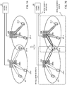
- FIGS. 7A and 7B illustrate configuration examples of a radio communication system according to the present embodiment.
- the radio communication system includes a plurality of radio base stations 10 (for example, Massive MIMO base stations), at least one user terminal 20, and control station 30.
- Each user terminal 20 is connected to at least one radio base station 10.
- user terminals 20-1 to 20-3 are connected to radio base station 10A
- user terminals 20-4 and 20-5 are connected to radio base station 10B.
- Control station 30 is connected to a plurality of radio base stations 10. Control station 30 monitors the amount of data transmission of each radio base station 10. Control station 30 instructs, for example, radio base station 10 with the amount of data transmission smaller than predetermined threshold T (that is, radio base station 10 with an extra assignable resource) to form beams for a peripheral site. Note that the processing similar to the processing by control station 30 may be executed by any of radio base stations 10.
- control station 30 detects that the amount of data transmission of radio base station 10B is smaller than threshold T in FIG. 7A . Therefore, control station 30 instructs radio base station 10B to change the BF weight to form beams for the site of neighboring radio base station 10A (details will be described later). For example, control station 30 here instructs radio base station 10B to form beams for user terminal 20-3 connected to radio base station 10A.
- radio base station 10B forms beams for user terminal 20-3 connected to radio base station 10A as shown in FIG. 7B . Therefore, user terminal 20-3 is connected to both of radio base station 10A and radio base station 10B.
- the beam control for user terminal 20-3 in radio base station 10A and radio base station 10B is, for example, the same as the processing described in Embodiment 2, and the details will not be described here.
- the extra resources in radio base station 10B can be effectively used to improve the system throughput.
- FIG. 8 is a flow chart showing operation of radio base station 10 and control station 30 according to the present embodiment. Note that in FIG. 8 , the same reference signs are provided to the same processing as in Embodiment 1 ( FIG. 4 ) or Embodiment 2 ( FIG. 6 ), and the description will not be repeated.
- each radio base station 10 first executes the beam-forming processing and the precoding processing in the site formed by each radio base station 10. More specifically, each radio base station 10 selects the BF weight in ST105 and computes the precoding matrix in ST112 to communicate with user terminals 20 connected to radio base station 10 (ST113).
- radio base station 10 has transmitted all of the data (information) to be transmitted to user terminals 20 (ST301: Yes), the processing illustrated in FIG. 8 ends.
- control station 30 monitors the amount of transmission of a plurality of radio base stations 10 (ST302). Control station 30 then determines whether there is radio base station 10 in which the monitored amount of data transmission is smaller than threshold T (ST303).
- Control station 30 does not do anything for radio base station 10 with the amount of data transmission equal to or greater than threshold T (ST303: No) and continues to monitor the amount of data transmission (ST302, ST303). Therefore, radio base station 10 with the amount of data transmission equal to or greater than threshold T continues the processing of ST111, ST112, and ST113.
- control station 30 instructs radio base station 10 with the amount of data transmission smaller than threshold T (ST303: Yes) to change the BF weight to form beams for a peripheral site.
- Radio base station 10 instructed to change the BF weight changes the BF weight (ST304).
- Radio base station 10 then generates, for example, the cooperative precoding matrix (ST203) as in Embodiment 2 and transmits the data (information) to user terminal 20 (ST113).
- the i-th radio base station 10 may delete L Ind beams selected according to equation 13, for example.
- l del arg min l ⁇ H i , j w i , l p + z i , j ⁇ 2
- i-th radio base station 10 selects an l add -th beam to be formed in a peripheral site (site formed by k-th radio base station 10 here) according to a maximum received power standard indicated in the following equation 14.
- the i-th radio base station 10 may newly form L Ind beams selected according to equation 14, for example.
- l add arg max x ⁇ H k , j w i , x p + z k , j ⁇ 2
- i-th radio base station 10 deletes the beams with little influence of deletion on the data transmission in the site of radio base station 10 (here, beams selected according to the minimum received power standard indicated by equation 13). Furthermore, i-th radio base station 10 changes the beams to beams highly efficient for the data transmission in the peripheral site (here, beams selected according to the maximum received power standard indicated in equation 14).
- i-th radio base station 10 and k-th radio base station 10 use, for example, the channel information (for example, equation 12) between both of radio base stations 10 and user terminal 20-3 to generate cooperative precoding matrix (P ISI ) for j-th user terminal 20 (ST203 shown in FIG. 8 ) as in Embodiment 2.
- the channel information for example, equation 12
- P ISI cooperative precoding matrix
- a site with a larger amount of data transmission may be selected from sites around the site formed by i-th radio base station 10, or a site may be selected based on another standard.
- the data transmitted from i-th radio base station 10 to j-th user terminal 20 may be transferred from k-th radio base station 10 through inter-base station communication section 105 (backhaul), for example.
- a plurality of radio base stations 10 can assign the resources (beams) that can be used by radio base stations 10 to user terminals 20 connected to other radio base stations 10 according to the usage of the resources (for example, deviation in amount of data transmission). Therefore, the resources of all of the sites can be efficiently used to control the beams.
- radio base station 10 may shift to the transmission of the discovery signal (ST101) after the judgement of the amount of data transmission in ST302 and change the BF weight based on the candidate weight information measured by using the discovery signal in ST304.
- radio base station 10 can use the candidate weight information (SNR or received power) reflecting the current channel status to change the BF weight, and the BF weight can be accurately deleted and selected.
- radio base station 10 with the amount of data transmission smaller than threshold T among radio base stations 10 executes the beam-forming (BF weight changing) processing to form the beams for user terminal 20 connected to radio base station 10 other than the radio base station 10 in the present embodiment. Therefore, radio base station 10 with the amount of data transmission smaller than threshold T executes the beam-forming (BF weight changing) processing to connect radio base station 10 and the user terminal connected to radio base station 10 other than the radio base station 10.
- radio base station 10 with a small amount of data transmission among radio base stations 10 cooperates to apply beams to the site formed by radio base station 10 with a large amount of data transmission to transmit data.
- the beams can be appropriately controlled in all of the sites in the multi-site environment, and the efficiency of the MU-MIMO transmission can be improved.
- the spatial separation processing for user terminal 20 is executed in consideration of the interference between the streams transmitted from radio base stations 10 as in Embodiment 2. Therefore, the interference between the streams can be reduced.
- the amount of data transmission is used as the amount of used resources of each radio base station 10 monitored by control station 30.
- the amount of used resources of radio base station 10 is not limited to the amount of data transmission in the present embodiment, and another parameter indicating the usage of resources in each radio base station 10, the deviation in the amount of used resources between radio base stations 10, or the like may also be used. Examples of the other parameter include the number of streams transmitted by radio base station 10 and the difference between the amounts of data transmitted between radio base stations 10.
- the standard based on the received power is used to change (delete and add) the BF weight as indicated in equation 13 and equation 14.
- the present embodiment is not limited to this, and for example, another standard based on the signal to interference power ratio may be used to change the BF weight.
- the reference signal is used to perform the channel estimation.
- the channel estimation value (channel information) may be acquired without using the reference signal in the channel estimation. In other words, it is only necessary to acquire the channel information indicating equivalent channel matrix (HW) including the BF weight in the channel estimation.
- HW equivalent channel matrix
- embodiments are not limited to this, and an operation similar to the operation in embodiments can be performed in a multi-site environment including three or more radio base stations 10.
- the block diagrams used to describe embodiments illustrate blocks on the basis of functions.
- the functional blocks are realized by an arbitrary combination of hardware and/or software. Means for realizing the functional blocks is not particularly limited. More specifically, the functional blocks may be realized by one physically and/or logically coupled apparatus. Two or more physically and/or logically separated apparatuses may be directly and/or indirectly (for example, wired and/or wireless) connected, and the plurality of apparatuses may realize the functional blocks.
- the radio base station, the user terminal, and the like may function as a computer that executes processing of a radio communication method of the present invention.
- FIG. 9 illustrates an example of a hardware configuration of the radio base station and the user terminal according to one embodiment of the present invention.
- Radio base station 10 and user terminal 20 may be physically constituted as a computer apparatus including processor 1001, memory 1002, storage 1003, communication apparatus 1004, input apparatus 1005, output apparatus 1006, bus 1007, and the like.
- radio base station 10 and user terminal 20 may include one or a plurality of apparatuses illustrated in the drawings or may not include part of the apparatuses.
- processor 1001 may be provided by one or more chips.
- radio base station 10 and user terminal 20 are realized by loading predetermined software (program) on the hardware of processor 1001, memory 1002, or the like.
- Processor 1001 performs operation, and the communication by communication apparatus 1004 or reading and/or writing of data in memory 1002 and storage 1003 is controlled.
- Processor 1001 operates, for example, an operating system to control the entire computer.
- Processor 1001 may be constituted by a central processing unit (CPU) including an interface for peripheral apparatus, a control apparatus, an operation apparatus, a register, and the like.
- CPU central processing unit
- discovery signal generation section 101, candidate weight multiplication section 102, reference signal generation section 103, access point selection section 104, weight selection section 106, judgement section 107, precoding matrix generation section 108, data generation section 109, precoding section 110, beam-forming section 111, candidate weight information measurement section 203, channel estimation section 204, postcoding matrix generation section 205, postcoding section 206, data reception section 207, and the like may be realized by processor 1001.
- Processor 1001 executes various types of processing according to a program (program code), a software module, or data loaded from storage 1003 and/or communication apparatus 1004 to memory 1002.
- the program used is a program for causing the computer to execute at least part of the operation described in embodiments.
- at least part of the functional blocks constituting radio base station 10 and user terminal 20 may be realized by a control program stored in memory 1002 and operated by processor 1001, and the other functional blocks may also be similarly realized.
- the various types of processing are executed by one processor 1001 in the description, the various types of processing may be executed by two or more processors 1001 at the same time or in succession.
- Processor 1001 may be provided by one or more chips. Note that the program may be transmitted from a network through a telecommunication line.
- Memory 1002 is a computer-readable recording medium and may be constituted by, for example, at least one of a ROM (Read Only Memory), an EPROM (Erasable Programmable ROM), an EEPROM (Electrically Erasable Programmable ROM), and a RAM (Random Access Memory).
- Memory 1002 may be called a register, a cache, a main memory (main storage apparatus), or the like.
- Memory 1002 can save a program (program code), a software module, and the like that can be executed to carry out the radio communication method according to one embodiment of the present invention.
- Storage 1003 is a computer-readable recording medium and may be constituted by, for example, at least one of an optical disk such as a CD-ROM (Compact Disc ROM), a hard disk drive, a flexible disk, a magneto-optical disk (for example, a compact disc, a digital versatile disk, or a Blue-ray (registered trademark) disk), a smart card, a flash memory (for example, a card, a stick, or a key drive), a floppy (registered trademark) disk, and a magnetic strip.
- Storage 1003 may be called an auxiliary storage apparatus.
- the storage medium may be, for example, a database, a server, or other appropriate media including memory 1002 and/or storage 1003.
- Communication apparatus 1004 is hardware (transmission and reception device) for communication between computers through a wired and/or wireless network and is also called, for example, a network device, a network controller, a network card, or a communication module.
- a network device for example, a network controller, a network card, or a communication module.
- communication sections 112 and 202, antennas 113 and 201, inter-base station communication section 105, and the like may be realized by communication apparatus 1004.
- Input apparatus 1005 is an input device (for example, a keyboard, a mouse, a microphone, a switch, a button, or a sensor) that receives input from the outside.
- Output apparatus 1006 is an output device (for example, a display, a speaker, or an LED lamp) for output to the outside. Note that input apparatus 1005 and output apparatus 1006 may be integrated (for example, a touch panel).
- Bus 1007 may be set by a single bus or may be set by different buses between the apparatuses.
- radio base station 10 and user terminal 20 may include hardware, such as a microprocessor, a digital signal processor (DSP), an ASIC (Application Specific Integrated Circuit), a PLD (Programmable Logic Device), and an FPGA (Field Programmable Gate Array), and the hardware may realize part or all of the functional blocks.
- processor 1001 may be provided by at least one of these pieces of hardware.
- the notification of information is not limited to the modes and embodiments described in the present specification, and the information may be notified by other methods.
- the notification of information may be carried out by one or a combination of physical layer signaling (for example, DCI (Downlink Control Information) and UCI (Uplink Control Information)), higher layer signaling (for example, RRC (Radio Resource Control) signaling, MAC (Medium Access Control) signaling, broadcast information (MIB (Master Information Block), and SIB (System Information Block))), and other signals.
- the RRC signaling may be called an RRC message and may be, for example, an RRC connection setup message, an RRC connection reconfiguration message, or the like.
- LTE Long Term Evolution
- LTE-A Long Term Evolution-Advanced
- SUPER 3G IMT-Advanced
- 4G 5G
- FRA Full Radio Access
- W-CDMA registered trademark
- GSM registered trademark
- CDMA2000 Code Division Multiple Access 2000
- UMB Universal Mobile Broadband
- IEEE 802.11 Wi-Fi
- IEEE 802.16 WiMAX
- IEEE 802.20 UWB (Ultra-WideBand)
- Bluetooth registered trademark
- Specific operations performed by the base station (radio base station) in the specification may be performed by an upper node depending on the situation.
- Various operations performed for communication with a terminal in a network constituted by one or a plurality of network nodes including a base station can be obviously performed by the base station and/or a network node other than the base station (examples include, but not limited to, MME (Mobility Management Entity) and S-GW (Serving Gateway)).
- MME Mobility Management Entity
- S-GW Serving Gateway
- the information, the signals, and the like can be output from a higher layer (or a lower layer) to a lower layer (or a higher layer).
- the information, the signals, and the like may be input and output through a plurality of network nodes.
- the input and output information and the like may be saved in a specific place (for example, memory) or may be managed by a management table.
- the input and output information and the like can be overwritten, updated, or additionally written.
- the output information and the like may be deleted.
- the input information and the like may be transmitted to another apparatus.
- the judgement may be made based on a value expressed by 1 bit (0 or 1), based on a Boolean value (true or false), or based on comparison with a numerical value (for example, comparison with a predetermined value).
- the software should be broadly interpreted to mean an instruction, an instruction set, a code, a code segment, a program code, a program, a subprogram, a software module, an application, a software application, a software package, a routine, a subroutine, an object, an executable file, an execution thread, a procedure, a function, and the like.
- the software, the instruction, and the like may be transmitted and received through a transmission medium.
- a transmission medium such as a coaxial cable, an optical fiber cable, a twisted pair, and a digital subscriber line (DSL), and/or a wireless technique, such as an infrared ray, a radio wave, and a microwave
- the wired technique and/or the wireless technique is included in the definition of the transmission medium.
- the information, the signals, and the like described in the present specification may be expressed by using any of various different techniques.
- data, instructions, commands, information, signals, bits, symbols, chips, and the like that may be mentioned throughout the entire description may be expressed by one or an arbitrary combination of voltage, current, electromagnetic waves, magnetic fields, magnetic particles, optical fields, and photons.
- the channel and/or the symbol may be a signal.
- the signal may be a message.
- the component carrier (CC) may be called a carrier frequency, a cell, or the like.
- system and "network” used in the present specification can be interchangeably used.
- radio resources may be indicated by indices.
- the base station can accommodate one or a plurality of (for example, three) cells (also called sectors).
- the entire coverage area of the base station can be divided into a plurality of smaller areas, and each smaller area can provide a communication service based on a base station subsystem (for example, small base station for indoor, RRH: Remote Radio Head).
- a base station subsystem for example, small base station for indoor, RRH: Remote Radio Head.
- the term "cell” or “sector” denotes the base station that performs the communication service in the coverage and/or part or all of the coverage area of the base station subsystem.
- the terms “base station,” “eNB,” “cell,” and “sector” can be interchangeably used in the present specification.
- the base station may be called a fixed station, a NodeB, an eNodeB (eNB), an access point, a femto cell, a small cell, or the like.
- the user terminal may be called, by those skilled in the art, a mobile station, a subscriber station, a mobile unit, a subscriber unit, a wireless unit, a remote unit, a mobile device, a wireless device, a wireless communication device, a remote device, a mobile subscriber station, an access terminal, a mobile terminal, a wireless terminal, a remote terminal, a handset, a user agent, a mobile client, a client, or UE (User Equipment) or by some other appropriate terms.
- a mobile station a subscriber station, a mobile unit, a subscriber unit, a wireless unit, a remote unit, a mobile device, a wireless device, a wireless communication device, a remote device, a mobile subscriber station, an access terminal, a mobile terminal, a wireless terminal, a remote terminal, a handset, a user agent, a mobile client, a client, or UE (User Equipment) or by some other appropriate terms.
- UE User Equipment
- determining may encompasses a wide variety of actions. For example, “determining” may be regarded as judging, calculating, computing, processing, deriving, investigating, looking up (e.g., looking up in a table, a database or another data structure), ascertaining and the like. Also, “determining” may be regarded as receiving (e.g., receiving information), transmitting (e.g., transmitting information), inputting, outputting, accessing (e.g., accessing data in a memory) and the like. Also, “determining” may be regarded as resolving, selecting, choosing, establishing and the like. That is, “determining” may be regarded as a certain type of action related to determining.
- connection and coupling as well as any modifications of the terms mean any direct or indirect connection and coupling between two or more elements, and the terms can include cases in which one or more intermediate elements exist between two “connected” or “coupled” elements.
- the coupling or the connection between elements may be physical or logical coupling or connection or may be a combination of physical and logical coupling or connection.
- two elements can be considered to be “connected” or “coupled” to each other by using one or more electrical wires, cables, and/or printed electrical connections or by using electromagnetic energy, such as electromagnetic energy with a wavelength of a radio frequency domain, a microwave domain, or an optical (both visible and invisible) domain that are non-limited and non-inclusive examples.
- the reference signal can also be abbreviated as RS and may also be called a pilot depending on the applied standard.
- the correction RS may be called a TRS (Tracking RS), a PC-RS (Phase Compensation RS), a PTRS (Phase Tracking RS), or an additional RS.
- the demodulation RS and the correction RS may be called by other corresponding names.
- the demodulation RS and the correction RS may be prescribed by the same name (for example, demodulation RS).
- the radio frame may be constituted by one or a plurality of frames in the time domain.
- One or each of a plurality of frames may be called a subframe, a time unit, or the like in the time domain.
- the subframe may be further constituted by one or a plurality of slots in the time domain.
- the slot may be further constituted by one or a plurality of symbols (OFDM (Orthogonal Frequency Division Multiplexing) symbols, SC-FDMA (Single Carrier-Frequency Division Multiple Access) symbols, or the like) in the time domain.
- OFDM Orthogonal Frequency Division Multiplexing
- SC-FDMA Single Carrier-Frequency Division Multiple Access
- the radio frame, the subframe, the slot, a mini slot, and the symbol indicate time units in transmitting signals.
- the radio frame, the subframe, the slot, the mini slot, and the symbol may be called by other corresponding names.
- the base station creates a schedule for assigning a radio resource to each mobile station (such as frequency bandwidth that can be used by each mobile station and transmission power).
- the minimum time unit of scheduling may be called a TTI (Transmission Time Interval), or one mini slot may be called a TTI.
- one subframe may be called a TTI.
- a plurality of continuous subframes may be called a TTI.
- One slot may be called a TTI.
- the resource unit is a resource assignment unit of the time domain and the frequency domain, and the resource unit may include one or a plurality of continuous subcarriers in the frequency domain.
- One or a plurality of symbols may be included in the time domain of the resource unit, and the length may be one slot, one mini slot, one subframe, or one TTI.
- One TTI and one subframe may be constituted by one or a plurality of resource units.
- the resource unit may be called a resource block (RB), a physical resource block (PRB: Physical RB), a PRB pair, an RB pair, a scheduling unit, a frequency unit, or a subband.
- the resource unit may be constituted by one or a plurality of REs. For example, it is only necessary that one RE be a resource in a unit (for example, minimum resource unit) smaller than the resource unit serving as a resource assignment unit, and the naming is not limited to RE.
- the structure of the radio frame is exemplary only, and the number of subframes included in the radio frame, the number of slots included in the subframe, the number of mini slots included in the subframe, the numbers of symbols and resource blocks included in the slot, and the number of subcarriers included in the resource block can be changed in various ways.
- notification of predetermined information is not limited to explicit notification, and the notification of the predetermined information may be implicit (for example, by not notifying the predetermined information).
- An aspect of the present invention is useful for a mobile communication system.
Landscapes
- Engineering & Computer Science (AREA)
- Computer Networks & Wireless Communication (AREA)
- Signal Processing (AREA)
- Mobile Radio Communication Systems (AREA)
- Radio Transmission System (AREA)
Applications Claiming Priority (2)
| Application Number | Priority Date | Filing Date | Title |
|---|---|---|---|
| JP2017026241A JP2018133700A (ja) | 2017-02-15 | 2017-02-15 | 無線基地局及び無線通信方法 |
| PCT/JP2017/041584 WO2018150666A1 (fr) | 2017-02-15 | 2017-11-20 | Station de base sans fil, et procédé de communication sans fil |
Publications (2)
| Publication Number | Publication Date |
|---|---|
| EP3584953A1 true EP3584953A1 (fr) | 2019-12-25 |
| EP3584953A4 EP3584953A4 (fr) | 2021-03-03 |
Family
ID=63170146
Family Applications (1)
| Application Number | Title | Priority Date | Filing Date |
|---|---|---|---|
| EP17896429.2A Pending EP3584953A4 (fr) | 2017-02-15 | 2017-11-20 | Station de base sans fil, et procédé de communication sans fil |
Country Status (4)
| Country | Link |
|---|---|
| US (1) | US11387872B2 (fr) |
| EP (1) | EP3584953A4 (fr) |
| JP (1) | JP2018133700A (fr) |
| WO (1) | WO2018150666A1 (fr) |
Families Citing this family (2)
| Publication number | Priority date | Publication date | Assignee | Title |
|---|---|---|---|---|
| JP7010168B2 (ja) * | 2018-07-31 | 2022-01-26 | 日本電信電話株式会社 | 無線通信システム、通信方法および送信局装置 |
| WO2021033265A1 (fr) * | 2019-08-20 | 2021-02-25 | 日本電信電話株式会社 | Système de communication sans fil, procédé de communication sans fil, et dispositif de station de réception |
Family Cites Families (12)
| Publication number | Priority date | Publication date | Assignee | Title |
|---|---|---|---|---|
| US9755705B2 (en) * | 2008-08-07 | 2017-09-05 | Qualcomm Incorporated | Method and apparatus for supporting multi-user and single-user MIMO in a wireless communication system |
| US9077413B2 (en) * | 2010-06-15 | 2015-07-07 | Futurewei Technologies, Inc. | System and method for transparent coordinated beam-forming |
| JP5462144B2 (ja) * | 2010-12-10 | 2014-04-02 | 株式会社Nttドコモ | 無線中継局装置、無線基地局装置及び無線通信方法 |
| JP5767038B2 (ja) * | 2011-06-22 | 2015-08-19 | Kddi株式会社 | 無線通信システム、基地局制御装置、及び基地局制御方法 |
| US8768393B2 (en) * | 2011-06-30 | 2014-07-01 | Intel Corporation | Method and apparatus for interference mitigation in wireless systems |
| EP2677825B1 (fr) * | 2012-06-21 | 2014-08-06 | Alcatel Lucent | Appareil, émetteur-récepteur de station de base, procédé et programme informatique pour l'affectation d'une ressource radio |
| JP2014154916A (ja) * | 2013-02-05 | 2014-08-25 | Sharp Corp | 基地局装置、端末装置、通信システム、送信方法及び通信方法 |
| TW201438419A (zh) * | 2013-03-06 | 2014-10-01 | Interdigital Patent Holdings | 無線網路中干擾管理及干擾對齊 |
| JP5449602B2 (ja) * | 2013-07-09 | 2014-03-19 | 京セラ株式会社 | 無線通信システム及び無線端末 |
| US9872242B2 (en) * | 2014-01-31 | 2018-01-16 | Qualcomm Incorporated | Joint transmission of CSI-RS for channel state feedback and transmission point selection |
| US20160277942A1 (en) * | 2015-03-17 | 2016-09-22 | Qualcomm Incorporated | Load-aware channel state reference signal transmission |
| JP2017026241A (ja) | 2015-07-24 | 2017-02-02 | 株式会社ノーリツ | エネルギー量表示装置、並びに、給湯システム |
-
2017
- 2017-02-15 JP JP2017026241A patent/JP2018133700A/ja active Pending
- 2017-11-20 WO PCT/JP2017/041584 patent/WO2018150666A1/fr not_active Ceased
- 2017-11-20 EP EP17896429.2A patent/EP3584953A4/fr active Pending
- 2017-11-20 US US16/486,041 patent/US11387872B2/en active Active
Also Published As
| Publication number | Publication date |
|---|---|
| US11387872B2 (en) | 2022-07-12 |
| JP2018133700A (ja) | 2018-08-23 |
| US20200052745A1 (en) | 2020-02-13 |
| WO2018150666A1 (fr) | 2018-08-23 |
| EP3584953A4 (fr) | 2021-03-03 |
Similar Documents
| Publication | Publication Date | Title |
|---|---|---|
| US10897297B2 (en) | Transmission and reception apparatus | |
| JP7005190B2 (ja) | 信号処理装置、無線装置、フロントホールマルチプレクサ、ビーム制御方法、および信号合成方法 | |
| US10742279B2 (en) | User terminal and wireless communication method | |
| US10917160B2 (en) | Wireless base station, and wireless communication method | |
| EP3962144B1 (fr) | Dispositif de commande de communication et procédé de commande de communication | |
| US20160134397A1 (en) | Base station and control method | |
| US11736956B2 (en) | Base station | |
| EP3584953A1 (fr) | Station de base sans fil, et procédé de communication sans fil | |
| US11197305B2 (en) | Wireless base station and scheduling method | |
| JP6967358B2 (ja) | 無線基地局および送信電力制御方法 | |
| JP6994304B2 (ja) | 無線端末、送信電力制御方法、および無線基地局 | |
| US10848208B2 (en) | Wireless base station and wireless communication method | |
| US10985810B2 (en) | User terminal, wireless base station, and wireless communication method | |
| JP7141183B2 (ja) | 基地局及び基地局による通信制御方法 | |
| EP3429094B1 (fr) | Station de base | |
| JP7296489B2 (ja) | 通信ユニット、フロントホールマルチプレクサ、通信システム、及び通信方法 | |
| EP3783942B1 (fr) | Dispositif de station de base et procédé de communication | |
| EP3771114A1 (fr) | Station de base et procédé de transmission utilisant une station de base |
Legal Events
| Date | Code | Title | Description |
|---|---|---|---|
| STAA | Information on the status of an ep patent application or granted ep patent |
Free format text: STATUS: THE INTERNATIONAL PUBLICATION HAS BEEN MADE |
|
| PUAI | Public reference made under article 153(3) epc to a published international application that has entered the european phase |
Free format text: ORIGINAL CODE: 0009012 |
|
| STAA | Information on the status of an ep patent application or granted ep patent |
Free format text: STATUS: REQUEST FOR EXAMINATION WAS MADE |
|
| 17P | Request for examination filed |
Effective date: 20190823 |
|
| AK | Designated contracting states |
Kind code of ref document: A1 Designated state(s): AL AT BE BG CH CY CZ DE DK EE ES FI FR GB GR HR HU IE IS IT LI LT LU LV MC MK MT NL NO PL PT RO RS SE SI SK SM TR |
|
| AX | Request for extension of the european patent |
Extension state: BA ME |
|
| DAV | Request for validation of the european patent (deleted) | ||
| DAX | Request for extension of the european patent (deleted) | ||
| RIC1 | Information provided on ipc code assigned before grant |
Ipc: H04B 7/024 20170101ALI20200922BHEP Ipc: H04B 7/0456 20170101AFI20200922BHEP Ipc: H04B 7/0452 20170101ALI20200922BHEP Ipc: H04W 16/28 20090101ALI20200922BHEP Ipc: H04B 7/06 20060101ALN20200922BHEP |
|
| A4 | Supplementary search report drawn up and despatched |
Effective date: 20210129 |
|
| RIC1 | Information provided on ipc code assigned before grant |
Ipc: H04B 7/024 20170101ALI20210125BHEP Ipc: H04B 7/06 20060101ALN20210125BHEP Ipc: H04B 7/0456 20170101AFI20210125BHEP Ipc: H04B 7/0452 20170101ALI20210125BHEP Ipc: H04W 76/15 20180101ALI20210125BHEP Ipc: H04W 16/28 20090101ALI20210125BHEP |
|
| STAA | Information on the status of an ep patent application or granted ep patent |
Free format text: STATUS: EXAMINATION IS IN PROGRESS |
|
| 17Q | First examination report despatched |
Effective date: 20210517 |
|
| P01 | Opt-out of the competence of the unified patent court (upc) registered |
Effective date: 20230517 |