EP3585603B1 - Verfahren zur herstellung einer endlosbahn aus fasermaterial - Google Patents
Verfahren zur herstellung einer endlosbahn aus fasermaterial Download PDFInfo
- Publication number
- EP3585603B1 EP3585603B1 EP18711406.1A EP18711406A EP3585603B1 EP 3585603 B1 EP3585603 B1 EP 3585603B1 EP 18711406 A EP18711406 A EP 18711406A EP 3585603 B1 EP3585603 B1 EP 3585603B1
- Authority
- EP
- European Patent Office
- Prior art keywords
- web
- presser
- rigid cylinder
- corrugated
- cylinder
- Prior art date
- Legal status (The legal status is an assumption and is not a legal conclusion. Google has not performed a legal analysis and makes no representation as to the accuracy of the status listed.)
- Active
Links
Images



Classifications
-
- B—PERFORMING OPERATIONS; TRANSPORTING
- B31—MAKING ARTICLES OF PAPER, CARDBOARD OR MATERIAL WORKED IN A MANNER ANALOGOUS TO PAPER; WORKING PAPER, CARDBOARD OR MATERIAL WORKED IN A MANNER ANALOGOUS TO PAPER
- B31F—MECHANICAL WORKING OR DEFORMATION OF PAPER, CARDBOARD OR MATERIAL WORKED IN A MANNER ANALOGOUS TO PAPER
- B31F1/00—Mechanical deformation without removing material, e.g. in combination with laminating
- B31F1/20—Corrugating; Corrugating combined with laminating to other layers
- B31F1/22—Making webs in which the channel of each corrugation is longitudinal with the web feed
-
- D—TEXTILES; PAPER
- D21—PAPER-MAKING; PRODUCTION OF CELLULOSE
- D21H—PULP COMPOSITIONS; PREPARATION THEREOF NOT COVERED BY SUBCLASSES D21C OR D21D; IMPREGNATING OR COATING OF PAPER; TREATMENT OF FINISHED PAPER NOT COVERED BY CLASS B31 OR SUBCLASS D21G; PAPER NOT OTHERWISE PROVIDED FOR
- D21H25/00—After-treatment of paper not provided for in groups D21H17/00 - D21H23/00
- D21H25/005—Mechanical treatment
Definitions
- the present invention relates to a process for producing a continuous web of a longitudinally corrugated fibrous material.
- Corrugated paper sheets are known to be used on their own or even coupled with one or more smooth, i.e., non-corrugated, paper sheets, which give the corrugated paper sheet shape stability.
- a known technique for making corrugated paper sheets consists in passing a smooth paper sheet between a pair of cylinders, each affected on the whole side surface thereof by radially protruding veinings running parallel to the cylinder axis.
- the veinings are separated by grooves, in which the veinings of the other cylinder engage, forming a sort of toothed coupling between one another.
- two non-corrugated paper sheets are applied to one or both sides of the corrugated paper sheet, which stabilize the shape of the corrugated sheet and globally form the multilayer sheet of corrugated cardboard.
- Another drawback consists in that, in any case, this known technique does not allow to obtain a continuous paper web corrugated in the longitudinal direction.
- a drawback of this known solution consists in that the web passing between the two cylinders is affected by the corrugation process over the whole width thereof at the same time, and this determines a frequent longitudinal tearing of the web itself, with a consequent unacceptable production waste, which significantly affects the final cost of the product obtained.
- US 3104197 and US 3300367 relate to a process for obtaining a paper having a smooth and easily printable surface which may be extended both in the transverse direction and in the longitudinal direction.
- this is obtained by passing the starting web between a rigid cylinder provided with veinings and a cylinder externally coated with rubber so as to simultaneously carry out the embossing on the surface in contact with the rigid cylinder and the creping on the surface in contact with the rubber-coated cylinder.
- the exiting paper has a surface - the one that has come into contact with the rigid cylinder - which is substantially flat and smooth with recesses at the veinings of the rigid cylinder, while the other surface - the opposite one, which has come into contact with the rubber-coated cylinder - is flat with superficial ripples.
- GB 682 275 relates to a method of creping paper.
- a web a is corrugated or waved longitudinally e.g. by passing it between rollers band , includes the provision of means to advance the paper at the crests of the corrugations and to retard it at the troughs or vice versa so that transverse and oblique crepings are produced.
- US2890515 provides for passing a fabric between a web of a soft material and a rigid cylinder (i.e., of a non-elastic material) which is grooved and is heated. Furthermore, such solution provides for introducing a covering cloth or an endless continuous web of a flexible material between the rigid cylinder and the fabric to be treated, so as to create a ripple effect on the fabric, and this for ornamental purposes only.
- Figure 1 shows a conventional apparatus for producing a continuous web of multilayer cardboard comprising a first external web 2 of a fibrous material in general and of paper in particular, unwound from a first reel 4, a second external web 6 of paper, unwound from a second reel 8 and a third web 10, interposed between the two external webs 2, 6 and formed by a transversely corrugated paper web. It is obtained starting from a flat web 12, unwound from a reel 14 and passed between two forming cylinders 16, 16' affected on the side surface by a plurality of transverse veinings alternating with transverse grooves complementary to the veinings of the other forming cylinder 16', 16.
- the present invention provides a process and a plant with which a paper web may be obtained, corrugated in the longitudinal direction and resistant to foldings both parallel and orthogonal to the corrugations.
- the corrugations 26 affect the whole thickness of the paper web thus obtained and, in particular, both surfaces 23, 25 thereof.
- the process in accordance with the invention uses:
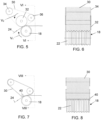
- the presser element may comprise a cylinder 20 coated in an elastically compressible material (see Figures 2 and 3 ) or a web 30 of an elastically compressible material which is pressed against the rigid cylinder 18 by a delimiting element which may be defined by a rotating element 32 (see Figures 5 and 6 ) or by a fixed element (see Figures 7 and 8 ).
- the process in accordance with the invention provides that, when a continuous web 24 of a non-corrugated fibrous material is passed between said rigid cylinder 18 and the presser, said web is also subjected, on at least one segment of the passage thereof between said rigid cylinder 18 and said presser, to a reduction of the speed of the surface 25 thereof in contact with said presser with respect to the speed of the surface 23 thereof in contact with said rigid cylinder.
- the method in accordance with the invention provides that the force for maintaining the presser adherent to said rigid cylinder and the speed reduction between the two surfaces 23, 25 of the web 24 are mutually defined, so that:
- the rigid cylinder 18 and the presser advance in directions opposite to one another.
- the rigid cylinder 18 is affected on the whole side surface thereof by a plurality of circumferential grooves 22 which are flanked and shaped so as to define a substantially corrugated profile reproducing the pattern of the corrugations 26 to be substantially obtained on the whole thickness of the web itself, and in particular on both surfaces 23, 25 of the exiting paper web.
- These grooves 22 preferably have a circumferential pattern and may suitably be continuous or discontinuous, and may have, in section, a curved corrugated pattern, preferably sinusoidal, or square wave, or of any other shape.
- the size of the grooves 22 may vary a lot, depending on the features of the corrugations 26 to be formed on the whole thickness of the paper web - and therefore on both surfaces 23, 25 of the web itself - according to market requirements.
- the grooves 22 have a depth and/or a pitch not smaller than 0.5 mm and, preferably, have a pitch and/or a depth of between about 1 and 20 mm and, more particularly, of between about 1.5 mm and 10 mm.
- the width (i.e., the transverse development) of the grooves 22 is substantially corresponding to the distance (always in the transverse direction) provided between the adjacent grooves 22.
- this allows to obtain, at the exit a paper web 24 with corrugations 26 in which portions of concavities, opposite with respect to that of the corresponding adjacent portions, alternate with constant pitch.
- the width of the segments raised (and deriving from the entry of the paper into the grooves 22) substantially corresponds to the width of the remaining segments (i.e., those not raised).
- the presser of an elastically compressible material 20 has a substantially smooth external surface.
- the presser of an elastically compressible material 20 has a hardness of between 70 and 240 PJ and preferably of between 120 and 220 PJ.
- the continuous paper web 24 - which is sent entering into the cylinder 18 and into the presser - has a degree of dryness of 40-95%, preferably of 60-85%.
- said continuous paper web 24, may be of any type, even of recycled waste fibers.
- said entering entering paper web 24 may be the one which is obtained directly in the paper mill, or may even be the one which, after being dried, is sent to the converter for subsequent processing; in the latter case, then, the paper web is previously wetted, before being sent entering into the cylinder 18 and into the presser.
- this wetting may be obtained by vaporizing or by spraying on the web 24 water or another suitable liquid or by passing the web itself through a tank containing this liquid.
- a pair of forming cylinders 18, 20, is provided, of which the cylinder 18 is made of a rigid material, preferably steel, while the cylinder 20 is made, at least externally, of an elastically compressible material, for example rubber or even steel, but with an external rubber coating.
- the rigid cylinder 18 is located in a lower position with respect to the cylinder of an elastically compressible material 20.
- Both cylinders 18, 20 are supported by a suitable structure (not shown) and are associated with respective motors, which drive them in rotation in a direction opposite to one another at different peripheral speeds.
- the cylinders 18, 20 are actuated so as to rotate at different speeds, and respectively at a speed V 1 for the rigid cylinder 18 and at a speed V 2 ⁇ V 1 for the cylinder 20 of an elastically compressible material.
- the cylinder of an elastically compressible material 20 and the rigid cylinder 18 have approximately the same diameter.
- the apparatus described herein operates as follows: when a continuous paper web 24 is passed between the two cylinders 18 and 20, the combined effect of the pressure existing in the contact area (nip) thereof and the different speeds thereof ensures that the cylinder 20 of an elastically compressible material presses the surface 23 of the paper web 24 against the rigid cylinder 18 to an extent suitable to lead the paper itself to be inserted into the grooves 22 (even without necessarily adhering to the bottom of the latter) and this effect, combined with the difference in peripheral speed of the two cylinders 18, 20 - and therefore the different speed which the two surfaces of the paper web 24 are subjected to - causes a transfer of energy from the cylinder of an elastically compressible material 20 to the surface 25 of the paper itself, to an extent sufficient both to deform the paper web 24, to imprint longitudinal corrugations 26 thereto along the whole width thereof and along the whole thickness thereof, and to create, in particular on the bottom of these corrugations thus obtained, a series of transverse ripples 27 which stabilize the shape of the corrugations themselves, even without the
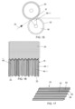
- FIG. 4 a portion of web obtained by the process described herein is shown in Figures 4 and 4A .
- the longitudinal corrugations 26 affect the whole thickness of the exiting paper web 24, and therefore both the surfaces 23 and 25 of the web itself.
- the transverse ripples 27 mainly and especially affect the surface 23 of the exiting paper web 24, i.e., the surface of the latter which has come into contact with the rigid cylinder 18.
- the transverse ripples 27 may also affect the surface 25 of the exiting paper web 24, i.e., the surface of the latter which has come into contact with the cylinder 20.
- the exiting paper web 24 has a thickness which has a substantially corrugated pattern and which remains substantially constant both in the longitudinal direction and in the transverse direction.
- the thickness of the paper web 24, exiting from the passage defined between the rigid cylinder 18 and the presser, is greater with respect to that of the paper web entering into said passage.
- the longitudinal braking given by the different speeds of the two cylinders 18, 20 has a double effect.
- the first effect consists in that the longitudinal braking determines a longitudinal compaction which is immediately used to obtain a greater transverse development, which in turn allows to obtain the corrugation without reducing the width of the exiting corrugated web.
- the web if the entering web has a width La and a length Lu, at the exit, the web itself has a width which is still La and a length Lu' with Lu' ⁇ Lu.
- the second effect consists in creating the transverse ripples 27 which give stability to the obtained corrugations.
- the rigid cylinder 18, which is circumferentially grooved, cooperates with a continuous web 30 of an elastically compressible material instead of with a cylinder of an elastically compressible material.
- the rigid cylinder 18 is positioned in a lower position with respect to the web 30.
- the rigid cylinder 18 has one or more of the features described for the previous embodiment.
- the web 30 is stretched between a series of return rollers, at least one of which is motorized, and is advanced, as in the case of the previous embodiment, at a peripheral speed V 2 ⁇ V 1 , where V 1 is the speed of rotation of the rigid cylinder. More particularly, the web 30 is stretched between a first roller 32, which presses it against the cylinder 18, a second roller 34 and a third roller 36, which are respectively located upstream and downstream of the first roller 32.
- the apparatus operates as in the previous case, in the sense that the lower peripheral speed V 2 of the web 30, with respect to the peripheral speed V 1 of the cylinder 18, causes on the paper web 24, interposed between the two, a braking effect, which, combined with the pressure exerted by the web itself on the paper web 24, in addition to pressing it on the bottom of the circumferential grooves 22 of the cylinder 18 to create the longitudinal corrugations 26 affecting the whole thickness of the web itself, creates on the bottom of the corrugations thus obtained a series of transverse ripples 27 which stabilize the shape of the corrugations themselves.
- the portion of web obtained is shown in Figures 4 and 4A .
- the longitudinal corrugations 26 affect the whole thickness of the exiting paper web 24, and therefore both the surfaces 23 and 25 of the web itself.
- the transverse ripples 27 mainly and especially affect the surface 23 of the exiting paper web 24, i.e., the surface of the latter which has come into contact with the rigid cylinder 18.
- the transverse ripples 27 may also affect the surface 25 of the exiting paper web 24, i.e., the surface of the latter which has come into contact with the web 30.
- the web 30 is supported and stretched by at least one return element 40 which is fixed, i.e., non-rotating.
- this fixed return element 40 is defined by a fixed bar.
- the return bar 40 has a significantly smaller diameter with respect to the diameter of the grooved cylinder 18.
- the fixed return element 40 is positioned and configured so as to locally press the web 30 against said cylinder 18 so as to significantly reduce the thickness thereof and to locally increase, consequently, the peripheral speed thereof in the short area of contact with the grooved cylinder 18.
- the various quantities involved are sized so that the speed of the web 30 at the point of passage between the roller 32 or the fixed element 40 and the cylinder 18 is equal to the peripheral speed V 1 of the lower cylinder 18.
- said corrugated web which exits the passage gap between the presser of an elastically compressible material and the rigid cylinder 18, is passed between two stabilizing rollers, preferably of steel, with a corrugated profile for pressing the corrugations of said web so as to stabilize and stiffen the corrugations themselves or, possibly, so as to vary and/or define the final shape (which may have a sinusoidal, trapezoidal, V or square/rectangular profile) of said corrugations.
- the pitch of the corrugated profile of the two subsequent stabilizing rollers corresponds to that of the rigid cylinder 18.
- the corrugated profile of the two subsequent stabilizing rollers may have a shape and/or a depth equal to or different from those of the rigid cylinder 18.
- the subsequent stabilizing rollers are activated at a speed corresponding to that of the corrugated web exiting from the passage gap between the presser of an elastically compressible material and the rigid cylinder 18.
- the longitudinal braking - which derives from the different speeds between the surface 23 of the web in contact with the rigid cylinder 18 and the surface 25 of the web which is in contact with the presser element (which may be defined by a cylinder 20 provided, at least externally, with a layer of an elastically compressible material or may be defined by a web 30 of an elastically compressible material which is pressed against the rigid cylinder 18 by a rotating element 32 and/or by a fixed element 40) - simultaneously has two effects connected to one another:
- the longitudinal braking given by the different peripheral speeds of the cylinder 18 with respect to the presser element 20 or 30 is defined on the basis of the force provided to maintain the presser itself adherent to said rigid cylinder 18, and vice versa.
- the braking and the force to maintain the presser adherent to said rigid cylinder 18 must be suitably and mutually defined and correlated.
- the difference between the peripheral speeds of the cylinder 18 with respect to the presser element 20 or 30 is about 5-30% while the force for maintaining the presser adherent to said rigid cylinder 18 is such that the linear pressure at the contact area (nip) is about 5-50 kg per linear centimeter of length of the contact area (nip).
- said braking and said force for maintaining the presser adherent to said rigid cylinder 18 depend on the moisture content of the fibers of the web 24 of a fibrous material when entering, on the weight of the web 24 of a fibrous material when entering, on the hardness of the layer of an elastically compressible material of the presser and on the size of the rigid cylinder 18 and of the presser.
- the forming cylinder 18 is hollow, has the side surface permeable and/or perforated 31 and houses therein a fixed suction chamber 29. It is connected to a suction pump (not shown) and is shaped as a cylindrical section with the two radial walls closed, and is open on the side facing towards the side surface 31 of the cylinder 18 and is affected along the perimeter edge by suitable sealing means sliding with respect to said side surface 31.
- the circumferential development of the opening of the suction chamber 29 facing towards the side surface 31 of the cylinder 18 is approximately equal to the circumferential length of the contact band between the cylinder 18 and the corrugated paper web 24 being formed.
- this suction chamber 29 is to ensure the adherence of said paper web 24 to the corrugated surface of the cylinder 18, even in the case of great hardness of the rubber forming or covering the cylinder 20 and/or in the case of deep corrugations, which are often desired, given the high dimensional stability which they give to the corrugated web.
- suction chamber 29 may advantageously be provided also in the case of a presser consisting of a rubber web 30 instead of a rubberized cylinder 20.
- the present disclosure provides that the cylinder 18, in addition to having the side surface affected by the circumferential grooves 22 aimed at creating the longitudinal corrugations 26 in the continuous web, is affected by circumferential incisions 41 in the grooves 22. They are designed to form in the longitudinal corrugations 26 of the corrugated web a series of small veinings 42, which run parallel to the corrugations themselves and give thereto a greater dimensional stability, by virtue of the increase of the deformation resistance thereof, in particular the compression resistance.
- the paper web 24 to be transversely corrugated must have a certain plasticity to be able to enter into the small incisions 41 obtained in the transverse grooves 22 of the rigid cylinder 18, and since the water content present in the paper web 24 may not be sufficient to give this plasticity required, it is also provided that, before the introduction thereof between the cylinder 18 and the presser 20, 30 it is subjected to wetting, to an extent suitable for bringing the dry content thereof to the optimum value, which is generally of between 40 and 95%, and is preferably of between 70 and 85%.
- this wetting may be obtained by vaporizing or by spraying on the web 24 water or another suitable liquid or by passing the web itself through a tank containing this liquid.
- the present invention allows to obtain paper with an overall pattern which is longitudinally corrugated for the whole thickness thereof and, in particular, in which the two opposite surfaces of the paper have both a longitudinally corrugated pattern.
- the present invention allows to obtain paper with transverse ripples which are present also and especially at the surface which was in contact with the rigid cylinder, while in US 3104197 and US 3300367 the transverse ripples are present only at the surface which was in contact with the element of an elastically compressible material while the other surface (the one which was in contact with the rigid cylinder) must necessarily be smooth in order to be printed.
- the longitudinally corrugated paper web obtained by the process described herein, may then be wound in a roll, just as it has been formed, and be transferred to a user, or may be coupled with another material to form a multilayer web with particular features.
- a paper web affected by transverse corrugations may be preferably applied to the web affected by the longitudinal corrugations, preferably in the same line and continuously, and this with an apparatus shown in Figure 10 , which differs from a conventional apparatus, of the type shown in Figure 1 , in that it carries out the coupling of a paper web 42, corrugated transversely with conventional techniques, with a paper web 44 corrugated longitudinally with techniques in accordance with the invention.
- one or both of the external flat paper webs 46, 46' may be affected by drawings 48 or by other ornamental and/or structural motifs, obtained by stretching between embossing rollers, precisely exploiting the extensibility features of the webs themselves (see Figure 14 ).
- a layer of a polymeric material may be applied, preferably continuously, to the web obtained in accordance with the invention and affected by the longitudinal corrugations 26 and by the transverse ripples 27.
- the coupling between the layers may be obtained at the ridges of the corrugations 26 by gluing or by clinching (in particular for tissue-type papers) or by other known techniques; and in all these cases, the features of the multilayer obtained, in addition to improving the folding resistance of the multilayer itself, make such resistance isotropic, i.e., substantially equal in each direction.
Landscapes
- Engineering & Computer Science (AREA)
- Mechanical Engineering (AREA)
- Machines For Manufacturing Corrugated Board In Mechanical Paper-Making Processes (AREA)
- Folding Of Thin Sheet-Like Materials, Special Discharging Devices, And Others (AREA)
- Catalysts (AREA)
- Exhaust Gas After Treatment (AREA)
Claims (14)
- Verfahren zur Herstellung einer Endlosbahn aus einem in Längsrichtung gewellten Fasermaterial, umfassend die Schritte, dass eine Endlosbahn (24) aus einem nicht gewellten Fasermaterial zwischen einem starren Zylinder (18), der an seiner Seitenoberfläche von Umfangsnuten (22) betroffen ist, die flankiert und so geformt sind, dass sie ein im Wesentlichen gewelltes Profil definieren, das das Muster der im Wesentlichen auf der gesamten Dicke der Bahn selbst zu erhaltenden Wellungen (26) wiedergibt, und einem Drücker (20, 30) geführt wird, der eine äußere Schicht aus einem elastisch komprimierbaren Material umfasst und die mit einer Kraft, die geeignet ist, die Endlosbahn (24) in die Nuten (22) eindringen zu lassen und so die Wellungen (26) zu erhalten, die die gesamte Dicke der Bahn selbst betreffen, an dem starren Zylinder (18) haftend gehalten wird, und gleichzeitig wird die Endlosbahn (24) an mindestens einem Segment des Durchgangs davon zwischen dem starren Zylinder (18) und dem Drücker (20, 30) einer Reduzierung der Geschwindigkeit der Oberfläche (25) davon in Kontakt mit dem Drücker (20, 30) in Bezug auf die Geschwindigkeit der Oberfläche (23) davon in Kontakt mit dem starren Zylinder (18) ausgesetzt, wobei die Kraft zum Halten des Drückers (20, 30) an dem starren Zylinder (18) haftend und die Geschwindigkeitsreduzierung zwischen den zwei Oberflächen (23, 25) der Bahn (24) gegenseitig definiert ist, so dass die Bahn (24), die aus dem Durchgang austritt, Folgendes aufweist:- ein in Längsrichtung gewelltes Muster auf beiden Oberflächen (23, 25) davon,- Querriffeln (27) zumindest auf der gewellten Oberfläche (23), die mit dem starren Zylinder (18) in Kontakt war,wobei das Verfahren ferner dadurch gekennzeichnet ist, dass:- die Differenz zwischen der Geschwindigkeit der Oberfläche (25) der Bahn (24) in Kontakt mit dem Drücker (20, 30) in Bezug auf die Geschwindigkeit der Oberfläche (23) davon in Kontakt mit dem starren Zylinder etwa 5-30% beträgt,- die Kraft zum Halten des Drückers an dem starren Zylinder (18) haftend derart ist, dass an der Kontaktfläche (Nip) ein linearer Druck von etwa 5-50 kg pro linearem Zentimeter Länge des Nips erzeugt wird.
- Verfahren nach Anspruch 1, dadurch gekennzeichnet, dass die aus dem Durchgang austretende Bahn (24) auch an der gewellten Oberfläche (25), die mit dem Drücker (20, 30) in Kontakt war, Querriffeln (27) aufweist.
- Verfahren nach einem oder mehreren der vorhergehenden Ansprüche, dadurch gekennzeichnet, dass ein starrer Zylinder (18) verwendet wird, wobei das durch die Nuten (22) definierte gewellte Profil eine Tiefe und/oder eine Steigung von nicht weniger als 0,5 mm aufweist.
- Verfahren nach einem oder mehreren der vorhergehenden Ansprüche, dadurch gekennzeichnet, dass die Kraft zum Halten des Drückers (20, 30) an dem starren Zylinder (18) haftend und die Geschwindigkeitsreduzierung zwischen den zwei Oberflächen (23, 25) der Bahn (24) so definiert sind, dass die Bahn (24), die aus dem Durchgang austritt, eine Breite (La) aufweist, die im Wesentlichen derjenigen der Bahn entspricht, wenn sie in den Durchgang eintritt.
- Verfahren nach einem oder mehreren der vorhergehenden Ansprüche, dadurch gekennzeichnet, dass die Kraft zum Halten des Drückers (20, 30) an dem starren Zylinder (18) haftend und die Geschwindigkeitsreduzierung zwischen den zwei Oberflächen (23, 25) der Bahn (24) so definiert sind, dass die Bahn (24), die aus dem Durchgang austritt, eine Länge (La) aufweist, die kleiner als diejenige der Bahn ist, wenn sie in den Durchgang eintritt.
- Verfahren nach einem oder mehreren der vorhergehenden Ansprüche, dadurch gekennzeichnet, dass ein starrer Zylinder (18) verwendet wird, der an seiner genuteten Seitenoberfläche von kontinuierlichen und diskontinuierlichen Umfangsnuten (22) betroffen ist.
- Verfahren nach einem oder mehreren der vorhergehenden Ansprüche, dadurch gekennzeichnet, dass ein Drücker (20) mit einer äußeren Schicht aus einem elastisch komprimierbaren Material mit einer Härte zwischen 70 und 240 PJ, vorzugsweise zwischen 120 und 220 PJ, verwendet wird.
- Verfahren nach einem oder mehreren der vorhergehenden Ansprüche, dadurch gekennzeichnet, dass ein Drücker (20) verwendet wird, der mindestens ein rotierendes Element (20, 30) mit einer äußeren Schicht aus einem elastisch komprimierbaren Material umfasst, die mit einer Oberfläche (25) der Bahn (24) in Kontakt ist.
- Verfahren nach einem oder mehreren der vorhergehenden Ansprüche, dadurch gekennzeichnet, dass ein Drücker (20) verwendet wird, der aus einem Zylinder besteht, der zumindest auf der äußeren Schicht seiner Seitenoberfläche aus einem elastisch komprimierbaren Material besteht.
- Verfahren nach dem vorhergehenden Anspruch, dadurch gekennzeichnet, dass der Druckzylinder (20) mit einer geringeren Umfangsgeschwindigkeit (V2) als die Umfangsgeschwindigkeit (V1) des starren Zylinders (18) vorgeschoben wird.
- Verfahren nach einem oder mehreren der vorhergehenden Ansprüche, dadurch gekennzeichnet, dass ein Drücker (30) verwendet wird, der aus einer Bahn aus einem elastisch komprimierbaren Material besteht, die durch ein Element (32, 40) zur Begrenzung des Durchgangsspaltes zwischen den zwei gegen den starren Zylinder (18) lokal gedrückt gehalten wird, wobei das Begrenzungselement ein rotierendes Element (32) oder ein feststehendes Element (40) umfasst.
- Verfahren nach einem oder mehreren der vorhergehenden Ansprüche, dadurch gekennzeichnet, dass die Bahn (30) aus einem elastisch komprimierbaren Material mit einer Umfangsgeschwindigkeit (V2) vorgeschoben wird, die niedriger ist als die Umfangsgeschwindigkeit (V1) des starren Zylinders (18).
- Verfahren nach einem oder mehreren der vorhergehenden Ansprüche, dadurch gekennzeichnet, dass die Umfangsgeschwindigkeit (V2) der Bahn (30) aus einem elastisch komprimierbaren Material, die Umfangsgeschwindigkeit (V1) des starren Zylinders (18) und der Durchgangsspalt zwischen dem starren Zylinder (18) und dem Begrenzungselement (32) so gewählt werden, dass die zwei Umfangsgeschwindigkeiten (V2, V1) an dem Durchgangsspalt im Wesentlichen gleich sind.
- Verfahren nach einem oder mehreren der vorhergehenden Ansprüche, dadurch gekennzeichnet, dass die aus dem Durchgangsspalt zwischen dem Drückerelement (20, 30) und dem starren Zylinder (18) austretende gewellte Bahn (24) mit mindestens einer nicht gewellten Bahn aus einem Fasermaterial, vorzugsweise aus einem dehnbaren Fasermaterial, gekoppelt und/oder zwischen zwei Stahlwalzen mit gewelltem Profil hindurchgeführt wird.
Applications Claiming Priority (2)
| Application Number | Priority Date | Filing Date | Title |
|---|---|---|---|
| IT102017000020032A IT201700020032A1 (it) | 2017-02-22 | 2017-02-22 | Procedimento ed apparecchiatura per produrre un nastro continuo di materiale fibroso ondulato longitudinalmente. |
| PCT/IB2018/051097 WO2018154475A1 (en) | 2017-02-22 | 2018-02-22 | A process and apparatus for making a continuous web of fibrous material |
Publications (3)
| Publication Number | Publication Date |
|---|---|
| EP3585603A1 EP3585603A1 (de) | 2020-01-01 |
| EP3585603B1 true EP3585603B1 (de) | 2025-05-21 |
| EP3585603C0 EP3585603C0 (de) | 2025-05-21 |
Family
ID=59253890
Family Applications (1)
| Application Number | Title | Priority Date | Filing Date |
|---|---|---|---|
| EP18711406.1A Active EP3585603B1 (de) | 2017-02-22 | 2018-02-22 | Verfahren zur herstellung einer endlosbahn aus fasermaterial |
Country Status (5)
| Country | Link |
|---|---|
| US (1) | US11400681B2 (de) |
| EP (1) | EP3585603B1 (de) |
| CN (1) | CN110612204B (de) |
| IT (1) | IT201700020032A1 (de) |
| WO (1) | WO2018154475A1 (de) |
Families Citing this family (2)
| Publication number | Priority date | Publication date | Assignee | Title |
|---|---|---|---|---|
| IT201700019934A1 (it) * | 2017-02-22 | 2018-08-22 | Giorgio Trani | Metodo ed apparecchiatura per produrre un nastro di materiale fibroso estensibile. |
| IT202000015811A1 (it) * | 2020-06-30 | 2021-12-30 | Giorgio Trani | Procedimento per produrre in continuo nastri di materiale fibroso ondulati in direzione macchina. |
Family Cites Families (22)
| Publication number | Priority date | Publication date | Assignee | Title |
|---|---|---|---|---|
| US1911001A (en) * | 1930-01-24 | 1933-05-23 | Continental Paper & Bag Corp | Creping machine |
| GB454427A (en) * | 1934-10-20 | 1936-09-29 | Dennison Victor Company Ltd | Improvements in or relating to laminated sheet material |
| US2623572A (en) * | 1949-05-25 | 1952-12-30 | Waldhof Zellstoff Fab | Apparatus for creping paper |
| GB682275A (en) * | 1949-05-25 | 1952-11-05 | Waldhof Zellstoff Fab | An improved process and apparatus for the creping or waving of paper and the like |
| US2890515A (en) * | 1952-07-02 | 1959-06-16 | Bleachers Ass Ltd | Apparatus for ornamentation of fabrics |
| US3104197A (en) * | 1959-06-29 | 1963-09-17 | Crown Zellerbach Corp | Extensible paper and the process of producing the same |
| US3188372A (en) * | 1961-08-25 | 1965-06-08 | Bird Machine Co | Machine and method for compacting materials |
| DE1211918B (de) * | 1963-07-15 | 1966-03-03 | Billeruds Ab | Maschine zum Schrumpfen von Papier |
| US3300368A (en) * | 1964-12-11 | 1967-01-24 | Crown Zellerbach Corp | Creped sheet materials and the process of producing the same |
| BE794261A (fr) * | 1972-01-19 | 1973-07-19 | B Projekt Ingf Ab | Procede de fabrication de mats continus en fibres agglomerees |
| FI284474A7 (de) * | 1974-09-27 | 1976-03-28 | Valmet Oy | |
| US5213872A (en) * | 1991-04-19 | 1993-05-25 | Stimsonite Corporation | Preprinted retroreflective highway sign and method for making the sign |
| US5508083A (en) * | 1993-05-19 | 1996-04-16 | Chapman, Jr.; Francis L. | Machine direction fluted combined corrugated containerboard |
| US5462488A (en) * | 1994-05-06 | 1995-10-31 | Stanley Stack, Jr. | Integrated card and business form assembly and method for fabricating same on label formation equipment |
| US20010048022A1 (en) * | 2000-04-27 | 2001-12-06 | Zoeckler Michael D. | Paperboard cartons with laminated reinforcing ribbons and transitioned scores and method of making same |
| ES2258119T3 (es) * | 2002-07-11 | 2006-08-16 | Bhs Corrugated Maschinen- Und Anlagenbau Gmbh | Cilindro estriado asi como procedimiento para su fabricacion. |
| WO2004020174A1 (en) * | 2002-08-30 | 2004-03-11 | Kimberly-Clark Worldwide, Inc. | Device and process for treating flexible web by stretching between intermeshing forming surfaces |
| US20090029840A1 (en) * | 2007-07-24 | 2009-01-29 | Jung Chi Chen | Corrugating machine |
| NZ568698A (en) * | 2008-05-27 | 2010-12-24 | Corcel Ip Ltd | Method and machine for forming single face corrugated board |
| US8691041B2 (en) * | 2008-08-08 | 2014-04-08 | The Procter And Gamble Company | Method of producing a composite multi-layered printed absorbent article |
| US9034230B2 (en) * | 2009-08-03 | 2015-05-19 | The Procter & Gamble Company | Method for making an elastomeric apertured web |
| ITVE20130038A1 (it) * | 2013-07-22 | 2015-01-23 | Giorgio Trani | Macchina e metodo per realizzare un nastro di materiale fibroso ad elevate estensibilita' longitudinale e trasveresale. |
-
2017
- 2017-02-22 IT IT102017000020032A patent/IT201700020032A1/it unknown
-
2018
- 2018-02-22 WO PCT/IB2018/051097 patent/WO2018154475A1/en not_active Ceased
- 2018-02-22 US US16/486,903 patent/US11400681B2/en active Active
- 2018-02-22 CN CN201880013391.7A patent/CN110612204B/zh active Active
- 2018-02-22 EP EP18711406.1A patent/EP3585603B1/de active Active
Also Published As
| Publication number | Publication date |
|---|---|
| IT201700020032A1 (it) | 2018-08-22 |
| EP3585603A1 (de) | 2020-01-01 |
| US11400681B2 (en) | 2022-08-02 |
| CN110612204A (zh) | 2019-12-24 |
| CN110612204B (zh) | 2023-01-03 |
| EP3585603C0 (de) | 2025-05-21 |
| WO2018154475A1 (en) | 2018-08-30 |
| US20210070006A1 (en) | 2021-03-11 |
Similar Documents
| Publication | Publication Date | Title |
|---|---|---|
| US7799168B2 (en) | Method of manufacturing a hygiene paper product, apparatus for such manufacture and hygiene paper product | |
| AU2002350230C1 (en) | Methods and system for manufacturing and finishing web products at high speed without reeling and unwinding | |
| CN113195208B (zh) | 绵纸产品以及生产所述绵纸产品的方法和设备 | |
| GB2166690A (en) | Embossed paper | |
| RU2008102737A (ru) | Крепированный с использованием материала лист для выдачных устройств | |
| MX2012010703A (es) | Metodo y aparato mejorado para formar un carton corrugado. | |
| JP7043410B2 (ja) | モールディングロールを使用して紙製品を作製する方法 | |
| CN108603339B (zh) | 用于制成纸产品的模塑辊 | |
| EP3585603B1 (de) | Verfahren zur herstellung einer endlosbahn aus fasermaterial | |
| EP1527898A1 (de) | Verfahren zur Herstellung eines Hyginepapierprodukts, Vorrichtung zur Herstellung und das Hygienepapierprodukt | |
| MY206390A (en) | Coreless rolls of a tissue paper product and methods of manufacturing coreless rolls | |
| AU2014411545B2 (en) | A rewinding machine and a winding method for a web of absorbent substrate | |
| EP1897682B1 (de) | Verfahren und Vorrichtung zur Herstellung eines geprägten und gefärbten Bahnmaterials | |
| GB2052586A (en) | Drying paper | |
| CZ324696A3 (cs) | Způsob výroby dvouvrstvé vlnité lepenky a zařízení k jeho provádění | |
| US12370771B2 (en) | Process for making in continuous production fibrous webs which are corrugated along the machine direction | |
| US11390999B2 (en) | Method and apparatus for producing a web of extensible fibrous material | |
| WO2013050810A1 (en) | Method for forming a web of transversely compacted fibrous material with voluminosity and extensibility increase, and apparatus for implementing the method | |
| IT202000022513A1 (it) | Metodo e impianto per la realizzazione di prodotti in carta tissue comprendenti almeno un velo goffrato | |
| RU17888U1 (ru) | Линия изготовления многослойного бумажного материала | |
| US20240003085A1 (en) | Paper making machine and process | |
| GB2380977A (en) | Embossing tissue paper | |
| RU2575082C2 (ru) | Усовершенствованный способ и установка для изготовления гофрированного картона | |
| CN111485442A (zh) | 一种高速多辊干燥造纸工艺 | |
| WO2010058084A1 (en) | Methods and apparatuses for manufacturing material web, system and fibre material product |
Legal Events
| Date | Code | Title | Description |
|---|---|---|---|
| STAA | Information on the status of an ep patent application or granted ep patent |
Free format text: STATUS: UNKNOWN |
|
| STAA | Information on the status of an ep patent application or granted ep patent |
Free format text: STATUS: THE INTERNATIONAL PUBLICATION HAS BEEN MADE |
|
| PUAI | Public reference made under article 153(3) epc to a published international application that has entered the european phase |
Free format text: ORIGINAL CODE: 0009012 |
|
| STAA | Information on the status of an ep patent application or granted ep patent |
Free format text: STATUS: REQUEST FOR EXAMINATION WAS MADE |
|
| 17P | Request for examination filed |
Effective date: 20190916 |
|
| AK | Designated contracting states |
Kind code of ref document: A1 Designated state(s): AL AT BE BG CH CY CZ DE DK EE ES FI FR GB GR HR HU IE IS IT LI LT LU LV MC MK MT NL NO PL PT RO RS SE SI SK SM TR |
|
| AX | Request for extension of the european patent |
Extension state: BA ME |
|
| DAV | Request for validation of the european patent (deleted) | ||
| DAX | Request for extension of the european patent (deleted) | ||
| STAA | Information on the status of an ep patent application or granted ep patent |
Free format text: STATUS: EXAMINATION IS IN PROGRESS |
|
| 17Q | First examination report despatched |
Effective date: 20221206 |
|
| GRAP | Despatch of communication of intention to grant a patent |
Free format text: ORIGINAL CODE: EPIDOSNIGR1 |
|
| STAA | Information on the status of an ep patent application or granted ep patent |
Free format text: STATUS: GRANT OF PATENT IS INTENDED |
|
| INTG | Intention to grant announced |
Effective date: 20240801 |
|
| GRAJ | Information related to disapproval of communication of intention to grant by the applicant or resumption of examination proceedings by the epo deleted |
Free format text: ORIGINAL CODE: EPIDOSDIGR1 |
|
| STAA | Information on the status of an ep patent application or granted ep patent |
Free format text: STATUS: EXAMINATION IS IN PROGRESS |
|
| GRAP | Despatch of communication of intention to grant a patent |
Free format text: ORIGINAL CODE: EPIDOSNIGR1 |
|
| STAA | Information on the status of an ep patent application or granted ep patent |
Free format text: STATUS: GRANT OF PATENT IS INTENDED |
|
| INTC | Intention to grant announced (deleted) | ||
| INTG | Intention to grant announced |
Effective date: 20241219 |
|
| GRAS | Grant fee paid |
Free format text: ORIGINAL CODE: EPIDOSNIGR3 |
|
| GRAA | (expected) grant |
Free format text: ORIGINAL CODE: 0009210 |
|
| STAA | Information on the status of an ep patent application or granted ep patent |
Free format text: STATUS: THE PATENT HAS BEEN GRANTED |
|
| AK | Designated contracting states |
Kind code of ref document: B1 Designated state(s): AL AT BE BG CH CY CZ DE DK EE ES FI FR GB GR HR HU IE IS IT LI LT LU LV MC MK MT NL NO PL PT RO RS SE SI SK SM TR |
|
| REG | Reference to a national code |
Ref country code: GB Ref legal event code: FG4D |
|
| REG | Reference to a national code |
Ref country code: CH Ref legal event code: EP |
|
| REG | Reference to a national code |
Ref country code: DE Ref legal event code: R096 Ref document number: 602018082079 Country of ref document: DE |
|
| REG | Reference to a national code |
Ref country code: IE Ref legal event code: FG4D |
|
| U01 | Request for unitary effect filed |
Effective date: 20250619 |
|
| U07 | Unitary effect registered |
Designated state(s): AT BE BG DE DK EE FI FR IT LT LU LV MT NL PT RO SE SI Effective date: 20250630 |
|
| PG25 | Lapsed in a contracting state [announced via postgrant information from national office to epo] |
Ref country code: ES Free format text: LAPSE BECAUSE OF FAILURE TO SUBMIT A TRANSLATION OF THE DESCRIPTION OR TO PAY THE FEE WITHIN THE PRESCRIBED TIME-LIMIT Effective date: 20250521 |
|
| PG25 | Lapsed in a contracting state [announced via postgrant information from national office to epo] |
Ref country code: NO Free format text: LAPSE BECAUSE OF FAILURE TO SUBMIT A TRANSLATION OF THE DESCRIPTION OR TO PAY THE FEE WITHIN THE PRESCRIBED TIME-LIMIT Effective date: 20250821 Ref country code: GR Free format text: LAPSE BECAUSE OF FAILURE TO SUBMIT A TRANSLATION OF THE DESCRIPTION OR TO PAY THE FEE WITHIN THE PRESCRIBED TIME-LIMIT Effective date: 20250822 |
|
| PG25 | Lapsed in a contracting state [announced via postgrant information from national office to epo] |
Ref country code: PL Free format text: LAPSE BECAUSE OF FAILURE TO SUBMIT A TRANSLATION OF THE DESCRIPTION OR TO PAY THE FEE WITHIN THE PRESCRIBED TIME-LIMIT Effective date: 20250521 |
|
| PG25 | Lapsed in a contracting state [announced via postgrant information from national office to epo] |
Ref country code: HR Free format text: LAPSE BECAUSE OF FAILURE TO SUBMIT A TRANSLATION OF THE DESCRIPTION OR TO PAY THE FEE WITHIN THE PRESCRIBED TIME-LIMIT Effective date: 20250521 |
|
| PG25 | Lapsed in a contracting state [announced via postgrant information from national office to epo] |
Ref country code: RS Free format text: LAPSE BECAUSE OF FAILURE TO SUBMIT A TRANSLATION OF THE DESCRIPTION OR TO PAY THE FEE WITHIN THE PRESCRIBED TIME-LIMIT Effective date: 20250821 |
|
| PG25 | Lapsed in a contracting state [announced via postgrant information from national office to epo] |
Ref country code: IS Free format text: LAPSE BECAUSE OF FAILURE TO SUBMIT A TRANSLATION OF THE DESCRIPTION OR TO PAY THE FEE WITHIN THE PRESCRIBED TIME-LIMIT Effective date: 20250921 |
|
| PG25 | Lapsed in a contracting state [announced via postgrant information from national office to epo] |
Ref country code: SM Free format text: LAPSE BECAUSE OF FAILURE TO SUBMIT A TRANSLATION OF THE DESCRIPTION OR TO PAY THE FEE WITHIN THE PRESCRIBED TIME-LIMIT Effective date: 20250521 |
|
| PG25 | Lapsed in a contracting state [announced via postgrant information from national office to epo] |
Ref country code: CZ Free format text: LAPSE BECAUSE OF FAILURE TO SUBMIT A TRANSLATION OF THE DESCRIPTION OR TO PAY THE FEE WITHIN THE PRESCRIBED TIME-LIMIT Effective date: 20250521 |
|
| PG25 | Lapsed in a contracting state [announced via postgrant information from national office to epo] |
Ref country code: SK Free format text: LAPSE BECAUSE OF FAILURE TO SUBMIT A TRANSLATION OF THE DESCRIPTION OR TO PAY THE FEE WITHIN THE PRESCRIBED TIME-LIMIT Effective date: 20250521 |
|
| U20 | Renewal fee for the european patent with unitary effect paid |
Year of fee payment: 9 Effective date: 20260216 |
|
| PLBE | No opposition filed within time limit |
Free format text: ORIGINAL CODE: 0009261 |
|
| STAA | Information on the status of an ep patent application or granted ep patent |
Free format text: STATUS: NO OPPOSITION FILED WITHIN TIME LIMIT |
|
| REG | Reference to a national code |
Ref country code: CH Ref legal event code: L10 Free format text: ST27 STATUS EVENT CODE: U-0-0-L10-L00 (AS PROVIDED BY THE NATIONAL OFFICE) Effective date: 20260402 |
|
| PGFP | Annual fee paid to national office [announced via postgrant information from national office to epo] |
Ref country code: GB Payment date: 20260216 Year of fee payment: 9 |
|
| 26N | No opposition filed |
Effective date: 20260224 |