EP3585689B1 - Appareil de distribution circulaire - Google Patents
Appareil de distribution circulaire Download PDFInfo
- Publication number
- EP3585689B1 EP3585689B1 EP17709346.5A EP17709346A EP3585689B1 EP 3585689 B1 EP3585689 B1 EP 3585689B1 EP 17709346 A EP17709346 A EP 17709346A EP 3585689 B1 EP3585689 B1 EP 3585689B1
- Authority
- EP
- European Patent Office
- Prior art keywords
- distribution apparatus
- circular distribution
- annular floor
- side wall
- elevation
- Prior art date
- Legal status (The legal status is an assumption and is not a legal conclusion. Google has not performed a legal analysis and makes no representation as to the accuracy of the status listed.)
- Active
Links
Images


Classifications
-
- B—PERFORMING OPERATIONS; TRANSPORTING
- B08—CLEANING
- B08B—CLEANING IN GENERAL; PREVENTION OF FOULING IN GENERAL
- B08B9/00—Cleaning hollow articles by methods or apparatus specially adapted thereto
-
- B—PERFORMING OPERATIONS; TRANSPORTING
- B08—CLEANING
- B08B—CLEANING IN GENERAL; PREVENTION OF FOULING IN GENERAL
- B08B9/00—Cleaning hollow articles by methods or apparatus specially adapted thereto
- B08B9/08—Cleaning containers, e.g. tanks
- B08B9/093—Cleaning containers, e.g. tanks by the force of jets or sprays
-
- B—PERFORMING OPERATIONS; TRANSPORTING
- B65—CONVEYING; PACKING; STORING; HANDLING THIN OR FILAMENTARY MATERIAL
- B65B—MACHINES, APPARATUS OR DEVICES FOR, OR METHODS OF, PACKAGING ARTICLES OR MATERIALS; UNPACKING
- B65B37/00—Supplying or feeding fluent-solid, plastic, or liquid material, or loose masses of small articles, to be packaged
- B65B37/04—Supplying or feeding fluent-solid, plastic, or liquid material, or loose masses of small articles, to be packaged by vibratory feeders
-
- B—PERFORMING OPERATIONS; TRANSPORTING
- B65—CONVEYING; PACKING; STORING; HANDLING THIN OR FILAMENTARY MATERIAL
- B65B—MACHINES, APPARATUS OR DEVICES FOR, OR METHODS OF, PACKAGING ARTICLES OR MATERIALS; UNPACKING
- B65B39/00—Nozzles, funnels or guides for introducing articles or materials into containers or wrappers
- B65B39/001—Nozzles, funnels or guides for introducing articles or materials into containers or wrappers with flow cut-off means, e.g. valves
- B65B39/002—Pivoting plates
-
- B—PERFORMING OPERATIONS; TRANSPORTING
- B65—CONVEYING; PACKING; STORING; HANDLING THIN OR FILAMENTARY MATERIAL
- B65G—TRANSPORT OR STORAGE DEVICES, e.g. CONVEYORS FOR LOADING OR TIPPING, SHOP CONVEYOR SYSTEMS OR PNEUMATIC TUBE CONVEYORS
- B65G47/00—Article or material-handling devices associated with conveyors; Methods employing such devices
- B65G47/52—Devices for transferring articles or materials between conveyors i.e. discharging or feeding devices
- B65G47/72—Devices for transferring articles or materials between conveyors i.e. discharging or feeding devices transferring materials in bulk from one conveyor to several conveyors, or vice versa
-
- B—PERFORMING OPERATIONS; TRANSPORTING
- B65—CONVEYING; PACKING; STORING; HANDLING THIN OR FILAMENTARY MATERIAL
- B65G—TRANSPORT OR STORAGE DEVICES, e.g. CONVEYORS FOR LOADING OR TIPPING, SHOP CONVEYOR SYSTEMS OR PNEUMATIC TUBE CONVEYORS
- B65G65/00—Loading or unloading
- B65G65/30—Methods or devices for filling or emptying bunkers, hoppers, tanks, or like containers, of interest apart from their use in particular chemical or physical processes or their application in particular machines, e.g. not covered by a single other subclass
- B65G65/34—Emptying devices
- B65G65/40—Devices for emptying otherwise than from the top
- B65G65/44—Devices for emptying otherwise than from the top using reciprocating conveyors, e.g. jigging conveyors
-
- B—PERFORMING OPERATIONS; TRANSPORTING
- B65—CONVEYING; PACKING; STORING; HANDLING THIN OR FILAMENTARY MATERIAL
- B65B—MACHINES, APPARATUS OR DEVICES FOR, OR METHODS OF, PACKAGING ARTICLES OR MATERIALS; UNPACKING
- B65B2210/00—Specific aspects of the packaging machine
- B65B2210/02—Plurality of alternative input or output lines or plurality of alternative packaging units on the same packaging line for improving machine flexibility
-
- B—PERFORMING OPERATIONS; TRANSPORTING
- B65—CONVEYING; PACKING; STORING; HANDLING THIN OR FILAMENTARY MATERIAL
- B65B—MACHINES, APPARATUS OR DEVICES FOR, OR METHODS OF, PACKAGING ARTICLES OR MATERIALS; UNPACKING
- B65B2210/00—Specific aspects of the packaging machine
- B65B2210/06—Sterilising or cleaning machinery or conduits
-
- B—PERFORMING OPERATIONS; TRANSPORTING
- B65—CONVEYING; PACKING; STORING; HANDLING THIN OR FILAMENTARY MATERIAL
- B65G—TRANSPORT OR STORAGE DEVICES, e.g. CONVEYORS FOR LOADING OR TIPPING, SHOP CONVEYOR SYSTEMS OR PNEUMATIC TUBE CONVEYORS
- B65G47/00—Article or material-handling devices associated with conveyors; Methods employing such devices
- B65G47/02—Devices for feeding articles or materials to conveyors
- B65G47/04—Devices for feeding articles or materials to conveyors for feeding articles
- B65G47/12—Devices for feeding articles or materials to conveyors for feeding articles from disorderly-arranged article piles or from loose assemblages of articles
- B65G47/14—Devices for feeding articles or materials to conveyors for feeding articles from disorderly-arranged article piles or from loose assemblages of articles arranging or orientating the articles by mechanical or pneumatic means during feeding
- B65G47/1407—Devices for feeding articles or materials to conveyors for feeding articles from disorderly-arranged article piles or from loose assemblages of articles arranging or orientating the articles by mechanical or pneumatic means during feeding the articles being fed from a container, e.g. a bowl
- B65G47/1414—Devices for feeding articles or materials to conveyors for feeding articles from disorderly-arranged article piles or from loose assemblages of articles arranging or orientating the articles by mechanical or pneumatic means during feeding the articles being fed from a container, e.g. a bowl by means of movement of at least the whole wall of the container
- B65G47/1421—Vibratory movement
Definitions
- the present invention relates to a circular distribution apparatus for distributing loose products, comprising a vertical central axis; an inlet; a base portion comprising an annular floor extending substantially horizontally in a radial direction relative to the vertical central axis; a plurality of outlets provided in said annular floor, each outlet comprising a valve member configured to move between a closed position and an opened position to allow the products to leave the apparatus through at least one of the outlets; a side wall entirely surrounding the annular floor; a central elevation disposed between the annular floor and the inlet, whereby the central elevation is placed beneath the inlet with a distance from the inlet to an apex of the elevation; and a vibrator configured to vibrate the base portion so that the loose products received on the base portion moves in a substantially circular manner around the elevation on the annular floor.
- the apparatus according to the invention may e.g. be used in the food or pharmaceutical industry, but it is not limited to any specific use.
- US 3 300 098 An apparatus of this kind is disclosed in US 3 300 098 showing several embodiments comprising generally a central inlet duct from where a loose material is directed onto an annular track surrounding a horizontal cone with a vertical central axis.
- the apparatus is vibrated to promote a circulating movement of the material in the track.
- several outlets are provided; each provided with a valve member for opening and closing the outlet for optionally letting material out through the respective outlets.
- Such apparatus of said general kind are known from i.a. US 3 877 586 , US 4 487 338 , US 4 966 273 , US 8 517 169 , and US 3 399 771 .
- the latter discloses an apparatus in which a base portion; a side wall portion comprising a side wall; and volutes extending therefrom to provide outlets, and a top portion are interconnected by means of clamping rings to form a casing.
- the circular distribution apparatus may be used for distributing a loose product to different recipients, one for each outlet, whereby a flow of the loose product to the respective recipients can be opened or stopped independently. This is due to the fact that factors relating to the respective recipient determine whether a recipient is ready or not for receiving the loose product.
- each or all recipients might be a packaging facility packaging the loose product in a packaging material which needs replenished from time to time, during which time the individual packaging facility is unable to handle incoming product.
- Loose products to be distributed by means of the circular distribution apparatus may e.g. be dried, semi-dried, moist, or frozen, grain, powder, granules, pellets, etc.
- sanitary is meant that the equipment should comply with relevant regulations within the food industry, among other USDA 3A (US), NZFSA (New Zealand) and/or EHEDG (EU) guidelines, and within the term “aseptic” within the pharma industry, respectively.
- USDA 3A US
- NZFSA New Zealand
- EU EHEDG
- sanitary and hygienic are herein used interchangeably.
- the inlet is provided centrally in a top portion connected to the side wall, and that the top portion, the elevation, the annular floor and the side wall provide a housing comprising a distribution chamber where at least the elevation, the annular floor and the side wall are provided integrally.
- the elevation, the annular floor and the side wall integrally results in providing a unitary lower part, i.e. the base portion, of the circular distributing apparatus.
- This lower part is the part of the apparatus that supports the loose product during use and by providing it integrally formed it may more easily be provided without joints and cracks that might otherwise accommodate small parts of the loose product which then hinders an effective cleaning and constitute a hygienic problem.
- Obtaining the elevation, the annular floor and the side wall integrally may be provided using suitable production methods such as sheet metal forming e.g. spinning or deep drawing; or welding and subsequently grinding and polishing the welding joints. These processes are mentioned as examples only and the invention is not limited by these. The skilled person in metal working is able to conceive other sanitary ways of providing such lower part.
- the angles between them are preferably kept large e.g. over 90° or kept easily accessible for cleaning fluid etc. and their creases to a minimum.
- this also minimizes the height and width of the apparatus and provides a more compact design than otherwise possible.
- the sum of the inlet duct, apparatus and outlet ducts can take up much less space, which is advantageous, since these distribution apparatuses generally service large size storage silos and vertical packaging lines, and any decrease in height/size also decrease the size requirements for the buildings/silos which houses them.
- the building costs are relatively large compared to the costs of the distributing apparatuses, a relatively large cost deduction can be foreseen for the entire plant.
- the top portion is provided integrally with the side wall which further enhances the possibility to improve the sanitary nature, reduces the risk of dusting and spillage, and promotes the compactness of the apparatus.
- the elevation has a summit centrally relative to the vertical central axis, and in a still further embodiment the elevation is of a conical, cupola or pyramid shape, without or only having a slight frustum.
- the inlet comprises a duct connection for connection with a duct.
- a hygienic connection may be obtained to an upstream part of a facility in which the apparatus of the invention is applied.
- the side wall is substantially vertical. This promotes an even speed of advancement at all levels of a loose product circulating on the annular floor during use, and further improves guiding the loose product down towards the outlets, e.g. having downwardly turning valve members.
- the annular floor has a radial width between the side wall and the elevation, and the outlets extend substantially throughout the entire radial width of the annular floor.
- the outlets extend substantially throughout the entire radial width of the annular floor.
- each outlet comprises a duct connection below the annular floor and below the valve member.
- a hygienic connection may be obtained to downstream parts of a facility in which the apparatus of the invention is applied.
- the circular distribution apparatus is provided for Cleaning-In-Place, so-called CIP, whereby at least parts of the apparatus are cleaned by subjecting such parts to a spray of a cleaning fluid without dismantling the apparatus.
- At least one CIP nozzle is provided within the duct connection below the valve member.
- a CIP procedure is provided for cleaning an outlet part below the valve member by a CIP procedure, thus further enhancing the hygienic nature of the apparatus.
- At least one CIP nozzle is provided inside the distribution chamber.
- a CIP procedure thus further enhancing the hygienic nature of the apparatus.
- annular floor is sectionally sloping along a circumferential direction towards the outlets.
- liquid used for cleaning e.g. by a CIP procedure
- the annular floor may be drained more conveniently from the annular floor towards the outlets.
- the housing is contained.
- the apparatus may be applied as a component of a facility having containment properties.
- Containment has been the focus of attention for a number of years, i.a., due to the increased awareness of the potential risk of operator exposure to the highly potent substances often involved within the pharmaceutical field or reducing the risk of powder explosion safety or allergenic exposure to the same personnel in the food and nutraceutical industry.
- exposure data may be evaluated for instance by a SMEPAC (Standardized Measurement of Equipment Particulate Airborne Concentration) test.
- SMEPAC Standardized Measurement of Equipment Particulate Airborne Concentration
- the term "contained” means that unit operations employed in e.g. a process to form tablets from e.g. powders of an Active Pharmaceutical Ingredient (API) and excipients are contained in modules used, which are therefore segregated from the surrounding environment. Thus, the operator does not need to have any direct access to the individual unit operations during operation, which may be accesses via the respective releasable inlet duct and outlet ducts.
- a desired level of containment is chosen among such levels as contained or dust-tight (10-100 mcg/m 3 ), high contained (1-10 mcg/m 3 ) and total contained ( ⁇ 1 mcg/m 3 ), and suitable equipment is chosen in accordance with the desired containment levels.
- the term "contained” within the context of the present application is defined by its level of containment according to suitable measurement, and is thus defined as at least dust-tight.
- the term “dust” may be defined as fine particles.
- the vibrator comprises a number of vibration members rigidly attached adjacent to the side wall.
- a low building height of the apparatus is obtained, i.e. a physically more compact apparatus is provided.
- the number of vibration members is two, and the two vibration members are positioned mutually diametrically opposite each other, relative to the vertical central axis, on an outside of the side wall.
- the vibration members per se may be of a previously known construction. By positioning them on the external side of the side wall instead of below the distribution chamber as shown in prior art, where the vibration also was transmitted indirectly by vibration members, it is now advantageously possible to position the apparatus selectively, e.g. on a top side thereof connected by wires to a ceiling of a silo or building, as shown in the appended drawings, or a bottom side, standing on a floor or hanging from a wall, rack or frame. Using in this way "direct” and not what is known as “indirect” vibration further enhances the compactness of the apparatus, and removes the risk of destructive resonances, which was a further issue with indirect vibrators.
- the apparatus comprises reinforcing ribs on an outside of the housing, preferably including radial ribs extending diametrically across the housing. This promotes the rigidity of the apparatus which further promotes the two or more vibration members to function as a single vibrator, and protects the apparatus from shearing forces experienced therefrom.
- the top portion comprises at least one inspection hatch to enable entry to dislodge stuck products and to inspect cleaning need or effectiveness of the at least one CIP-nozzle.
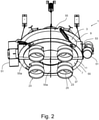
- the figures show as an example an embodiment of a circular distribution apparatus 1 according to the present invention.
- the circular distribution apparatus 1 comprises a housing 3 defining a distribution chamber 5, the housing 3 having a base portion 7 provided by a side wall 9, an annular floor 11, and a central elevation 13, i.e. the upper surface of the base portion 7 is raised at the centre and smoothly slants downwardly radially towards the periphery.
- the housing further comprises a top portion 17 with an inlet 19.
- the circular distribution apparatus 1 has a vertical central axis 21 and in the present embodiment the central elevation 13, the annular floor 11 and the side wall 9 are arranged as concentric circles around the vertical central axis 21.
- the annular floor 11 is extending substantially horizontally in radial directions that are radial relative to the vertical central axis 21, and the side wall 9 is vertical in the present embodiment.
- the side wall 9 is provided as an endless, continuous wall that entirely surrounds the annular floor 11.
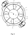
- a plurality of outlets 23 are provided in the annular floor 11. In the present embodiment four such outlets 23 are provided but any other number might be provided in accordance with actual needs.
- Each outlet 23 comprises a valve member 25 configured to move between a closed position (see Fig. 5 ) and an open position (see Figs. 2 and 6 ) to allow a product to leave the apparatus through one or more of the outlets 23 when open, and preferably no product or dust from these to leave them, when closed.
- the valve members 25 are in the present embodiment semi-circular gates to allow them to rotate around radially extending axes defined by journals 27 (see Figs. 5 and 6 ).
- valve members are configured to provide what might be seen as a semi-butterfly valve
- the valve members might alternatively be configured to provide ordinary fully circular butterfly valves or e.g. iris valves might be used.
- the valves must be able to withstand stress due to vibrations of the apparatus as will be explained below and preferably the valves should allow CIP i.e. sanitary cleaning in place after use as will also be explained below.
- outlet pipe stub 35 is extended by an outlet pipe stub 35 the latter being connected to an outlet flexible sleeve 37.
- the outlet pipe stub 35 is provided integrally with the material of the annular floor 11.
- the outlet pipe stub 35 and the outlet flexible sleeve 37 together constitute a duct connection for connection with a releasable outlet duct, as it will be explained below.
- the central elevation 13 is placed beneath the inlet 19 and is in the present embodiment formed as a cone with a summit 39 positioned at the vertical central axis 21.
- the elevation 13 is disposed between the annular floor 11 and the inlet 19 to receive product from the inlet 19 and redirect this product to the annular floor 11.
- the distance from the inlet 19 to the apex of the elevation 13 can be selected according to type of product expected to be distributed by the apparatus 1, in particular relative to the product's fragility, size, bounce-ability and other factors determining a suitable distance for the product to fall and distribute into the circular vibration flow in the distribution chamber 5.
- the elevation 13, the annular floor 11 and the side wall 9 are integral, in the embodiment shown made from stainless steel sheet material. Other easily cleaned metals may alternatively be utilized, such as grade steel, iron, and the like. Other materials may also be employed, e.g. plastics, ceramics or the like.
- the elevation 13, the annular floor 11 and the side wall 9 may in an embodiment be made by spinning or deep drawing a blank or by welding together blank pieces and subsequently grinding and polishing the welding joints to provide an internal surface of the base portion free of joints or cracks to provide an easy-to-clean surface.
- the top portion 17 comprises integrally, i.e. in one unit, a conical section 41, an annular section 43 and an inlet pipe stub 45; the latter being connected to an inlet flexible sleeve 47 to provide the inlet 19.
- the inlet pipe stub 45 and the inlet flexible sleeve 47 together constitute a duct connection for connection with a releasable inlet duct, as it will be explained below.
- the conical section 41 comprises a number of inspection hatches 49.
- the number of inspection hatches 49 is four, but any other number might be chosen.
- the inspection hatches 49 may be embodied as disclosed in the applicant's elder international patent application published under No. WO 2016/189110 A1 .
- the top portion 17 may in the present embodiment be connected to the side wall 9 by welding and the surface of the welding internally of the distribution chamber 5 may subsequently be grinded and polished to provide an internal surface of the distribution chamber 5 free of joints or cracks to provide an easy-to-clean internal surface of the distribution chamber 5.
- the circular distribution apparatus 1 includes a vibrator configured to vibrate the housing 3 including the base portion 7 so that product received on the base portion moves in a substantially circular manner around the central elevation 13 on the annular floor 11 inside the distribution chamber 5.
- the vibrator comprises two vibration members 51 attached directly and rigidly to the side wall via brackets 53.
- the vibration members 51 may in the present embodiment be of a kind known per se and comprising an asymmetric load rotated by a motor around an axis of rotation extending in a longitudinal direction of the respective vibration member 51.
- the axes of rotation of the two vibration members 51 extend in respective, mutually parallel, tangential planes on opposite sides of the housing 3.
- the axes of rotation are tilted relative to the vertical by in opposite directions by angles of similar size, e.g. 35°.
- the housing 3 including the base portion 7 and especially the annular floor 11 are imparted a circulating movement of an amplitude of e.g. 5-15 mm, e.g. 12 mm, as it is known in the art, whereby a product or products resting on the annular floor 11 will be imparted a unidirectional circulating movement around the vertical axis 21 on the annular floor 11.
- reinforcing ribs 55 are provided to provide the housing as a rigid body into which the vibrations provided by the vibration members 51 are induced as by a unitary vibrator.
- the reinforcing ribs 55 comprise radial ribs 55a extending diametrically across the housing 3.
- the circular distribution apparatus 1 is provided for eased cleaning by a Cleaning In Place (CIP) procedure i.e. without dismantling the apparatus.
- CIP Cleaning In Place
- an outlet CIP nozzle 57 see Fig. 4
- a distribution chamber CIP nozzle 59 is provided inside the distribution chamber 5, see Fig. 6 .
- the distribution chamber CIP nozzle 59 is of a construction known per se and is shown enlarged in Fig. 7 .
- the distribution chamber CIP nozzle 59 comprises a spherical body covered with nozzle openings for the distribution chamber CIP nozzle 59 during a cleaning procedure to spray cleaning liquid in all directions to clean the entire inner surface of the distribution chamber 5.
- the outlet CIP nozzles 57 are in the shown embodiment of a construction similar to the construction of the distribution chamber CIP nozzle 59, but may be different or not be provided at all, according to need and/or product.
- the annular floor 11 is sloping slightly towards the outlets 23.
- sections of the annular floor are sloping 0°-5°, especially 1°-3°, e.g. 2°, from radial lines 61 towards the outlets 23.
- the respective sections of the annular floor 11 between the radial lines 61 and the outlets 23 are sloping in circumferential directions towards the outlets 23.
- the central elevation 13 is formed as a cone i.e. it is conical shaped. In the alternative, it might e.g. be pyramid shaped, with three or more side faces. Likewise, the side wall 9 and the adjoining outer part of the annular floor 11 are in the embodiment shown circular, but they might be polygonal. However, to facilitate cleaning and drying out during CIP the circular embodiment is preferred.
- the central elevation 13 may in addition to its conical portion comprise a transition, such as a low vertical transition wall 63 between said conical portion and the annular floor 11, see Fig. 6 .
- the housing 3 is contained. This provides for incorporating the circular distribution apparatus 1 into facilities and product handling plants, where containment is pursued or needed.
- the apparatus may be used as a module within pharma, and may be contained as defined in the ISPE-Guide "Assessing the Particulate Containment Performance of Pharmaceutical Equipment” mentioned in the opening part of the present description.
- Containment of a facility provides for protecting operators against products being processed as mentioned above. However, it is also possible that containment or dust-free conditions are pursued in order to protect delicate products being processed against the environments.
- the housing 3 being contained entails that the walls of the housing, including the side wall 9, are tight to the chosen level, that the connections between the inlet and outlet pipe stubs 45, 35 and their respective flexible sleeves 47,37 and also the further connections with the releasable inlet and outlet ducts are correspondingly tight, and that any penetration of the material of the housing 3 such as for the journals 27 of the valve members 25 are made in a correspondingly tight manner. Likewise, the inspection hatches 49 must be correspondingly tight when closed.
- the circular distribution apparatus 1 is suspended for the housing 3 to be able to perform a circulating vibration movement imparted by the vibrator.
- the circular distributing apparatus 1 is suspended by four wires 65 attached via springs 67 to brackets 69 that may e.g. be attached to a ceiling or another fixed structure not shown.
- a releasable inlet duct, not shown, is connected to the inlet flexible sleeve 47, and releasable outlet ducts, likewise not shown, are connected to the outlet flexible sleeves 37. Due to the presence of the inlet and outlet flexible sleeves 47, 37 the housing 3 may perform its circulating vibration movement without the releasable inlet and outlet duct vibrating correspondingly.
- a flow of product to be distributed is introduced into the housing 3 through the releasable inlet duct and the inlet 19.
- the vibrator is activated to impart circulating vibration movement directly to the housing 3.
- the product introduced into the housing 3 will accordingly slide via the central elevation 13 to be evenly distributed on the annular floor 11 where the product will circulate around the vertical central axis 21.
- the valve members 25 are according to actual needs opened and the product on the annular floor 11 will exit through the outlets 23 when arriving at an outlet 23 with a valve member 25 in its opened position. Due to the fact that the valve members 25 extend throughout the entire width, i.e. the radial extent, of the annular floor 11, any product circulating on the annular floor 11 will exit through the outlets 23.
- the circular distribution apparatus may e.g. be applied in the food industry such as for a dairy product and the product to be distributed may be shredded or ball-sized frozen cheese.
- the diameter of the distribution chamber 5 might be e.g. 125 cm to provide a distribution capacity of 50,000 l/hr, or other sizes to suit other needs and capacities.
- a diameter of the distribution chamber of around 10-80 cm may be appropriate.
Landscapes
- Engineering & Computer Science (AREA)
- Mechanical Engineering (AREA)
- Filling Or Emptying Of Bunkers, Hoppers, And Tanks (AREA)
- Crushing And Pulverization Processes (AREA)
- Cleaning In General (AREA)
- Prostheses (AREA)
- Electron Sources, Ion Sources (AREA)
- Pens And Brushes (AREA)
Claims (16)
- Appareil de distribution circulaire destiné à distribuer des produits en vrac, comprenant :un axe central vertical (21) ;une entrée (19) positionnée de manière centrale par rapport à l'axe central vertical (21) ;une partie de base (7) comprenant un plancher annulaire (11) s'étendant sensiblement horizontalement dans une direction radiale par rapport à l'axe central vertical (21) ;une pluralité de sorties (23) situées dans ledit plancher annulaire (11), chaque sortie (23) comprenant un élément de vanne (25) conçu pour se déplacer entre une position fermée et une position ouverte pour permettre aux produits de quitter l'appareil par au moins une des sorties (23) ;une paroi latérale (9) entourant entièrement le plancher annulaire (11) ;une élévation centrale (13) disposée entre le plancher annulaire (11) et l'entrée (19), l'élévation centrale (13) étant placée sous l'entrée (19) avec une distance de l'entrée (19) à un sommet de l'élévation (13) ; etun vibreur (51) conçu pour faire vibrer la partie de base (7) de sorte que les produits reçus sur la partie de base (7) se déplacent d'une manière sensiblement circulaire autour de l'élévation (13) sur le plancher annulaire (11), caractérisé en ce que l'entrée (19) est située dans une partie supérieure (17) reliée à la paroi latérale (9), et en ce que la partie supérieure (17), l'élévation (13), le plancher annulaire (11) et la paroi latérale (9) fournissent un logement (3) comprenant une chambre de distribution (5), où au moins l'élévation (13), le plancher annulaire (11) et la paroi latérale (9) sont fournis d'un seul tenant.
- Appareil de distribution circulaire selon la revendication 1, caractérisé en ce que la partie supérieure (17) est fournie d'un seul tenant avec la paroi latérale (11).
- Appareil de distribution circulaire selon la revendication 1 ou 2, caractérisé en ce que l'élévation (13) a un sommet central (39) par rapport à l'axe central vertical (21).
- Appareil de distribution circulaire selon la revendication 3, caractérisé en ce que l'élévation (13) a une forme conique, de coupole ou de pyramide, sans ou avec seulement un léger tronc.
- Appareil de distribution circulaire selon l'une quelconque des revendications précédentes, caractérisé en ce que l'entrée (19) comprend un raccord de conduit (45, 47) pour un raccordement avec un conduit.
- Appareil de distribution circulaire selon l'une quelconque des revendications précédentes, caractérisé en ce que la paroi latérale (9) est sensiblement verticale.
- Appareil de distribution circulaire selon l'une quelconque des revendications précédentes, caractérisé en ce que le plancher annulaire (11) a une largeur radiale entre la paroi latérale (9) et l'élévation (13), et en ce que les sorties (23) s'étendent sur toute la largeur radiale du plancher annulaire (11).
- Appareil de distribution circulaire selon l'une quelconque des revendications précédentes, caractérisé en ce que chaque sortie (23) comprend un raccord de conduit (35, 37) sous le plancher annulaire (11) et sous l'élément de vanne (25).
- Appareil de distribution circulaire selon la revendication 8, caractérisé en ce qu'au moins une buse CIP (57) est située à l'intérieur d'au moins un des raccords de conduit (35, 37) sous l'élément de vanne (25).
- Appareil de distribution circulaire selon l'une quelconque des revendications précédentes, caractérisé en ce qu'au moins une buse CIP (59) est située à l'intérieur de la chambre de distribution (5).
- Appareil de distribution circulaire selon l'une quelconque des revendications précédentes, caractérisé en ce que le plancher annulaire (11) est incliné en section le long d'une direction circonférentielle vers les sorties (23).
- Appareil de distribution circulaire selon l'une quelconque des revendications précédentes, caractérisé en ce que le logement (3) est contenu, c'est-à-dire étanche à la poussière.
- Appareil de distribution circulaire selon l'une quelconque des revendications précédentes, caractérisé en ce que le vibreur comprend un certain nombre d'éléments de vibration (51) fixés de manière rigide et adjacente à la paroi latérale (9).
- Appareil de distribution circulaire selon la revendication 13, caractérisé en ce que le nombre d'éléments de vibration (51) est de deux, et les deux éléments de vibration (51) sont positionnés mutuellement diamétralement opposés l'un à l'autre, par rapport à l'axe central vertical (21), sur un extérieur de la paroi latérale (9).
- Appareil de distribution circulaire selon l'une quelconque des revendications précédentes, caractérisé en ce qu'il comprend des nervures de renforcement (55) sur un extérieur du logement, comprenant de préférence des nervures radiales (55a) s'étendant diamétralement à travers le logement (3).
- Appareil de distribution circulaire selon l'une quelconque des revendications précédentes, caractérisé en ce que la partie supérieure (17) comprend au moins une trappe d'inspection (49).
Applications Claiming Priority (1)
| Application Number | Priority Date | Filing Date | Title |
|---|---|---|---|
| PCT/DK2017/050051 WO2018153415A1 (fr) | 2017-02-24 | 2017-02-24 | Appareil de distribution circulaire |
Publications (2)
| Publication Number | Publication Date |
|---|---|
| EP3585689A1 EP3585689A1 (fr) | 2020-01-01 |
| EP3585689B1 true EP3585689B1 (fr) | 2022-01-26 |
Family
ID=58261463
Family Applications (1)
| Application Number | Title | Priority Date | Filing Date |
|---|---|---|---|
| EP17709346.5A Active EP3585689B1 (fr) | 2017-02-24 | 2017-02-24 | Appareil de distribution circulaire |
Country Status (7)
| Country | Link |
|---|---|
| US (1) | US11458516B2 (fr) |
| EP (1) | EP3585689B1 (fr) |
| CN (1) | CN110520360A (fr) |
| AU (1) | AU2017400335A1 (fr) |
| DK (1) | DK3585689T3 (fr) |
| SG (1) | SG11201906577RA (fr) |
| WO (1) | WO2018153415A1 (fr) |
Families Citing this family (3)
| Publication number | Priority date | Publication date | Assignee | Title |
|---|---|---|---|---|
| CN118748920A (zh) * | 2022-03-31 | 2024-10-08 | 爱适瑞卫生健康产品有限公司 | 用于幅状吸收材料的分配器的出口组件 |
| CN116040278B (zh) * | 2023-01-03 | 2025-07-01 | 大连华锐国际工程有限公司 | 一种防冻结无卡阻分料装置 |
| CN120564899B (zh) * | 2025-07-31 | 2025-09-30 | 河津市炬华铝业有限公司 | 一种基于数据分析的氢氧化铝生产质量检测方法及系统 |
Family Cites Families (30)
| Publication number | Priority date | Publication date | Assignee | Title |
|---|---|---|---|---|
| US2827062A (en) * | 1954-03-19 | 1958-03-18 | Nitsche Karl Paul Wolfgang | Conveying apparatus |
| US3255857A (en) * | 1964-03-09 | 1966-06-14 | O B Armstrong & Son | Rotary turnhead |
| DE1432726A1 (de) * | 1964-11-24 | 1968-11-28 | Quester Fa Wilh | Vorrichtung zum Beschicken mehrerer Zigarettenmaschinen mit Schnittabak |
| US3399771A (en) | 1966-07-26 | 1968-09-03 | Bohdan D. Hryniowski | Distributors of material |
| US3563420A (en) * | 1969-06-17 | 1971-02-16 | Charles H Ansley | Vibratory evacuator |
| US3650401A (en) * | 1969-11-28 | 1972-03-21 | Midwestern Ind Inc | Apparatus for vibrating a material separator |
| US3756372A (en) * | 1971-02-24 | 1973-09-04 | Nuclear Waste Systems Co | Apparatus for removal of stored material from storage containers |
| AT315050B (de) | 1972-01-25 | 1974-05-10 | Quester Fa Wilh | Vorrichtung zum Beschicken einer Vielzahl von Zigarettenmaschinen mit Schnittabak |
| US3971493A (en) * | 1974-08-26 | 1976-07-27 | David Michael Williams | Combination transportable container and dispensing receiver |
| AU535683B2 (en) * | 1979-11-21 | 1984-03-29 | Hitachi Limited | Hopper discharge details |
| JPS616419Y2 (fr) | 1979-12-05 | 1986-02-26 | ||
| US4276157A (en) * | 1980-01-28 | 1981-06-30 | Haight Ehrick K | Combination feeder and sifter |
| GB2078209B (en) | 1980-06-26 | 1984-07-25 | Jadal Process Equipment Ltd | Vibratory dispenser for granular or powder material |
| US4384535A (en) * | 1981-10-14 | 1983-05-24 | Mckelvie Alastair H | Solid fuel burning furnace |
| JPS5899633U (ja) | 1981-12-25 | 1983-07-06 | 株式会社石田衡器製作所 | 組合せ計量装置の分散供給装置 |
| JPS58177831A (ja) * | 1982-04-14 | 1983-10-18 | Shinko Electric Co Ltd | ビンデイスチヤ−ジヤ |
| US5046643A (en) * | 1987-12-11 | 1991-09-10 | Kinergy Corporation | Vibratory type storage bin arrangement with internal baffling and low profile bottom |
| US4844289A (en) * | 1987-12-11 | 1989-07-04 | Kinergy Corporation | Vibratory type storage bin arrangement with low profile bottom and rectilinear discharge chute characteristics |
| US4960229A (en) * | 1987-12-11 | 1990-10-02 | Kinergy Corporation | Vibratory type storage bin arrangement with internal baffling and low profile bottom |
| US5305912A (en) * | 1992-11-12 | 1994-04-26 | Johnston Robert E | Granular material flow divider |
| IT1304113B1 (it) | 1998-12-17 | 2001-03-07 | Simionato Spa | Complesso di distribuzione di articoli sfusi in macchine imbustatrici |
| DE102004031037A1 (de) * | 2004-06-25 | 2006-01-12 | Schmidt, Hermann | Förderstromverteiler für Schüttgüter |
| DK176356B1 (da) * | 2005-05-25 | 2007-09-24 | Bilwinco As | Fordelingsenhed med skubbeenhed |
| WO2010132667A2 (fr) * | 2009-05-13 | 2010-11-18 | M-I L.L.C. | Evacuation de séparateur sanitaire sans espace |
| JP2012532817A (ja) * | 2009-07-09 | 2012-12-20 | コンアグラ フーヅ ラム ウェストン インコーポレイテッド | 品目分配兼分類システム |
| DE102011009303A1 (de) | 2010-09-24 | 2012-03-29 | Andocksysteme G. Untch Gmbh | Mehrfachklappenvorrichtung für ein kontaminationsfreies Verbinden zweier Gebinde oder Leitungen sowie Passiv- und Aktivklappe hierfür |
| US9782801B2 (en) * | 2015-04-06 | 2017-10-10 | Kason Corporation | Vibratory screener with an adapter frame |
| EP3097988A1 (fr) | 2015-05-27 | 2016-11-30 | GEA Scan-Vibro A/S | Appareil vibrant et procédé permettant d'améliorer la durabilité d'un tel appareil |
| CN205345441U (zh) * | 2016-02-05 | 2016-06-29 | 富阳市福士得食品有限公司 | 一种食品包装机械输送分料装置 |
| CN105752368A (zh) | 2016-04-22 | 2016-07-13 | 柳州蓓蒂芬科技有限公司 | 乳制品设备 |
-
2017
- 2017-02-24 US US16/488,353 patent/US11458516B2/en active Active
- 2017-02-24 EP EP17709346.5A patent/EP3585689B1/fr active Active
- 2017-02-24 DK DK17709346.5T patent/DK3585689T3/da active
- 2017-02-24 CN CN201780085152.8A patent/CN110520360A/zh active Pending
- 2017-02-24 AU AU2017400335A patent/AU2017400335A1/en not_active Abandoned
- 2017-02-24 SG SG11201906577RA patent/SG11201906577RA/en unknown
- 2017-02-24 WO PCT/DK2017/050051 patent/WO2018153415A1/fr not_active Ceased
Non-Patent Citations (1)
| Title |
|---|
| None * |
Also Published As
| Publication number | Publication date |
|---|---|
| US11458516B2 (en) | 2022-10-04 |
| US20200038921A1 (en) | 2020-02-06 |
| EP3585689A1 (fr) | 2020-01-01 |
| WO2018153415A1 (fr) | 2018-08-30 |
| DK3585689T3 (da) | 2022-04-25 |
| CN110520360A (zh) | 2019-11-29 |
| SG11201906577RA (en) | 2019-09-27 |
| AU2017400335A1 (en) | 2019-08-01 |
Similar Documents
| Publication | Publication Date | Title |
|---|---|---|
| EP3585689B1 (fr) | Appareil de distribution circulaire | |
| US9174224B2 (en) | Continuously operating centrifuge | |
| DK201500043U3 (en) | Combination Weighing Apparatus | |
| JP2004130310A (ja) | 垂直調整器を有する、粒子形状物質を取り扱うための装置 | |
| EP3196611A1 (fr) | Dispositif de pesage associatif | |
| US20160370222A1 (en) | Conbination scale | |
| CN105564936A (zh) | 一种自清洁饲料出料输送装置 | |
| CN111757772A (zh) | 用于通过萃取和/或浸渍对散装材料进行高压处理的装置和方法及用途 | |
| EP0695214B1 (fr) | Installation de traitement de poudres ou de granules | |
| DK201770142A1 (en) | Circular Distribution Apparatus | |
| WO2003099685A2 (fr) | Ensemble permettant de distribuer des particules solides a charger | |
| CN107074386B (zh) | 用于从处理机中排出松散制品的装置 | |
| JPH02503400A (ja) | 粉体の造粒用流動床装置 | |
| US7922798B2 (en) | Granulator device | |
| SE468787B (sv) | Anordning foer behandling av runda foeremaal, t ex tvaettning av golfbollar | |
| CN107949434B (zh) | 流化床设备的产品容器和流化床设备 | |
| RU2844429C1 (ru) | Рукав загрузочный | |
| EP3326937A2 (fr) | Appareil pour la manipulation de produits en vrac et système de décharge muni d'un tel appareil | |
| JP4015089B2 (ja) | 粒状物の定量分取装置 | |
| WO2020183510A1 (fr) | Appareil pour alimenter des objets en vrac dans une machine de traitement et procédé d'alimentation correspondant | |
| US10981200B2 (en) | Processing method and device for small parts | |
| US2702635A (en) | Material handling | |
| US10696502B2 (en) | Method and apparatus to reduce volume occupied by dry particulate commodities during transportation or storage | |
| RU2255890C1 (ru) | Устройство для перегрузки сыпучих материалов из мягких контейнеров | |
| CN119568554A (zh) | 一种生物角质样品采集保存装置及其使用方法 |
Legal Events
| Date | Code | Title | Description |
|---|---|---|---|
| STAA | Information on the status of an ep patent application or granted ep patent |
Free format text: STATUS: UNKNOWN |
|
| STAA | Information on the status of an ep patent application or granted ep patent |
Free format text: STATUS: THE INTERNATIONAL PUBLICATION HAS BEEN MADE |
|
| PUAI | Public reference made under article 153(3) epc to a published international application that has entered the european phase |
Free format text: ORIGINAL CODE: 0009012 |
|
| STAA | Information on the status of an ep patent application or granted ep patent |
Free format text: STATUS: REQUEST FOR EXAMINATION WAS MADE |
|
| 17P | Request for examination filed |
Effective date: 20190924 |
|
| AK | Designated contracting states |
Kind code of ref document: A1 Designated state(s): AL AT BE BG CH CY CZ DE DK EE ES FI FR GB GR HR HU IE IS IT LI LT LU LV MC MK MT NL NO PL PT RO RS SE SI SK SM TR |
|
| AX | Request for extension of the european patent |
Extension state: BA ME |
|
| DAV | Request for validation of the european patent (deleted) | ||
| DAX | Request for extension of the european patent (deleted) | ||
| STAA | Information on the status of an ep patent application or granted ep patent |
Free format text: STATUS: EXAMINATION IS IN PROGRESS |
|
| 17Q | First examination report despatched |
Effective date: 20200930 |
|
| RIC1 | Information provided on ipc code assigned before grant |
Ipc: B08B 9/00 20060101ALI20210804BHEP Ipc: B08B 9/093 20060101ALI20210804BHEP Ipc: B65B 39/00 20060101ALI20210804BHEP Ipc: B08B 9/032 20060101ALI20210804BHEP Ipc: B65G 47/72 20060101ALI20210804BHEP Ipc: B65G 47/19 20060101ALI20210804BHEP Ipc: B65G 47/14 20060101ALI20210804BHEP Ipc: B65G 65/44 20060101ALI20210804BHEP Ipc: B65B 37/04 20060101AFI20210804BHEP |
|
| GRAP | Despatch of communication of intention to grant a patent |
Free format text: ORIGINAL CODE: EPIDOSNIGR1 |
|
| STAA | Information on the status of an ep patent application or granted ep patent |
Free format text: STATUS: GRANT OF PATENT IS INTENDED |
|
| INTG | Intention to grant announced |
Effective date: 20210924 |
|
| GRAS | Grant fee paid |
Free format text: ORIGINAL CODE: EPIDOSNIGR3 |
|
| GRAA | (expected) grant |
Free format text: ORIGINAL CODE: 0009210 |
|
| STAA | Information on the status of an ep patent application or granted ep patent |
Free format text: STATUS: THE PATENT HAS BEEN GRANTED |
|
| AK | Designated contracting states |
Kind code of ref document: B1 Designated state(s): AL AT BE BG CH CY CZ DE DK EE ES FI FR GB GR HR HU IE IS IT LI LT LU LV MC MK MT NL NO PL PT RO RS SE SI SK SM TR |
|
| REG | Reference to a national code |
Ref country code: GB Ref legal event code: FG4D |
|
| REG | Reference to a national code |
Ref country code: CH Ref legal event code: EP |
|
| REG | Reference to a national code |
Ref country code: AT Ref legal event code: REF Ref document number: 1465118 Country of ref document: AT Kind code of ref document: T Effective date: 20220215 |
|
| REG | Reference to a national code |
Ref country code: IE Ref legal event code: FG4D |
|
| REG | Reference to a national code |
Ref country code: DE Ref legal event code: R096 Ref document number: 602017052734 Country of ref document: DE |
|
| REG | Reference to a national code |
Ref country code: DK Ref legal event code: T3 Effective date: 20220422 |
|
| REG | Reference to a national code |
Ref country code: LT Ref legal event code: MG9D |
|
| REG | Reference to a national code |
Ref country code: NL Ref legal event code: MP Effective date: 20220126 |
|
| REG | Reference to a national code |
Ref country code: AT Ref legal event code: MK05 Ref document number: 1465118 Country of ref document: AT Kind code of ref document: T Effective date: 20220126 |
|
| PG25 | Lapsed in a contracting state [announced via postgrant information from national office to epo] |
Ref country code: NL Free format text: LAPSE BECAUSE OF FAILURE TO SUBMIT A TRANSLATION OF THE DESCRIPTION OR TO PAY THE FEE WITHIN THE PRESCRIBED TIME-LIMIT Effective date: 20220126 |
|
| PG25 | Lapsed in a contracting state [announced via postgrant information from national office to epo] |
Ref country code: SE Free format text: LAPSE BECAUSE OF FAILURE TO SUBMIT A TRANSLATION OF THE DESCRIPTION OR TO PAY THE FEE WITHIN THE PRESCRIBED TIME-LIMIT Effective date: 20220126 Ref country code: RS Free format text: LAPSE BECAUSE OF FAILURE TO SUBMIT A TRANSLATION OF THE DESCRIPTION OR TO PAY THE FEE WITHIN THE PRESCRIBED TIME-LIMIT Effective date: 20220126 Ref country code: PT Free format text: LAPSE BECAUSE OF FAILURE TO SUBMIT A TRANSLATION OF THE DESCRIPTION OR TO PAY THE FEE WITHIN THE PRESCRIBED TIME-LIMIT Effective date: 20220526 Ref country code: NO Free format text: LAPSE BECAUSE OF FAILURE TO SUBMIT A TRANSLATION OF THE DESCRIPTION OR TO PAY THE FEE WITHIN THE PRESCRIBED TIME-LIMIT Effective date: 20220426 Ref country code: LT Free format text: LAPSE BECAUSE OF FAILURE TO SUBMIT A TRANSLATION OF THE DESCRIPTION OR TO PAY THE FEE WITHIN THE PRESCRIBED TIME-LIMIT Effective date: 20220126 Ref country code: HR Free format text: LAPSE BECAUSE OF FAILURE TO SUBMIT A TRANSLATION OF THE DESCRIPTION OR TO PAY THE FEE WITHIN THE PRESCRIBED TIME-LIMIT Effective date: 20220126 Ref country code: ES Free format text: LAPSE BECAUSE OF FAILURE TO SUBMIT A TRANSLATION OF THE DESCRIPTION OR TO PAY THE FEE WITHIN THE PRESCRIBED TIME-LIMIT Effective date: 20220126 Ref country code: BG Free format text: LAPSE BECAUSE OF FAILURE TO SUBMIT A TRANSLATION OF THE DESCRIPTION OR TO PAY THE FEE WITHIN THE PRESCRIBED TIME-LIMIT Effective date: 20220426 |
|
| PG25 | Lapsed in a contracting state [announced via postgrant information from national office to epo] |
Ref country code: PL Free format text: LAPSE BECAUSE OF FAILURE TO SUBMIT A TRANSLATION OF THE DESCRIPTION OR TO PAY THE FEE WITHIN THE PRESCRIBED TIME-LIMIT Effective date: 20220126 Ref country code: LV Free format text: LAPSE BECAUSE OF FAILURE TO SUBMIT A TRANSLATION OF THE DESCRIPTION OR TO PAY THE FEE WITHIN THE PRESCRIBED TIME-LIMIT Effective date: 20220126 Ref country code: GR Free format text: LAPSE BECAUSE OF FAILURE TO SUBMIT A TRANSLATION OF THE DESCRIPTION OR TO PAY THE FEE WITHIN THE PRESCRIBED TIME-LIMIT Effective date: 20220427 Ref country code: FI Free format text: LAPSE BECAUSE OF FAILURE TO SUBMIT A TRANSLATION OF THE DESCRIPTION OR TO PAY THE FEE WITHIN THE PRESCRIBED TIME-LIMIT Effective date: 20220126 Ref country code: AT Free format text: LAPSE BECAUSE OF FAILURE TO SUBMIT A TRANSLATION OF THE DESCRIPTION OR TO PAY THE FEE WITHIN THE PRESCRIBED TIME-LIMIT Effective date: 20220126 |
|
| PG25 | Lapsed in a contracting state [announced via postgrant information from national office to epo] |
Ref country code: IS Free format text: LAPSE BECAUSE OF FAILURE TO SUBMIT A TRANSLATION OF THE DESCRIPTION OR TO PAY THE FEE WITHIN THE PRESCRIBED TIME-LIMIT Effective date: 20220526 |
|
| REG | Reference to a national code |
Ref country code: CH Ref legal event code: PL |
|
| REG | Reference to a national code |
Ref country code: BE Ref legal event code: MM Effective date: 20220228 |
|
| REG | Reference to a national code |
Ref country code: DE Ref legal event code: R097 Ref document number: 602017052734 Country of ref document: DE |
|
| PG25 | Lapsed in a contracting state [announced via postgrant information from national office to epo] |
Ref country code: SM Free format text: LAPSE BECAUSE OF FAILURE TO SUBMIT A TRANSLATION OF THE DESCRIPTION OR TO PAY THE FEE WITHIN THE PRESCRIBED TIME-LIMIT Effective date: 20220126 Ref country code: SK Free format text: LAPSE BECAUSE OF FAILURE TO SUBMIT A TRANSLATION OF THE DESCRIPTION OR TO PAY THE FEE WITHIN THE PRESCRIBED TIME-LIMIT Effective date: 20220126 Ref country code: RO Free format text: LAPSE BECAUSE OF FAILURE TO SUBMIT A TRANSLATION OF THE DESCRIPTION OR TO PAY THE FEE WITHIN THE PRESCRIBED TIME-LIMIT Effective date: 20220126 Ref country code: MC Free format text: LAPSE BECAUSE OF FAILURE TO SUBMIT A TRANSLATION OF THE DESCRIPTION OR TO PAY THE FEE WITHIN THE PRESCRIBED TIME-LIMIT Effective date: 20220126 Ref country code: LU Free format text: LAPSE BECAUSE OF NON-PAYMENT OF DUE FEES Effective date: 20220224 Ref country code: EE Free format text: LAPSE BECAUSE OF FAILURE TO SUBMIT A TRANSLATION OF THE DESCRIPTION OR TO PAY THE FEE WITHIN THE PRESCRIBED TIME-LIMIT Effective date: 20220126 Ref country code: CZ Free format text: LAPSE BECAUSE OF FAILURE TO SUBMIT A TRANSLATION OF THE DESCRIPTION OR TO PAY THE FEE WITHIN THE PRESCRIBED TIME-LIMIT Effective date: 20220126 |
|
| PG25 | Lapsed in a contracting state [announced via postgrant information from national office to epo] |
Ref country code: AL Free format text: LAPSE BECAUSE OF FAILURE TO SUBMIT A TRANSLATION OF THE DESCRIPTION OR TO PAY THE FEE WITHIN THE PRESCRIBED TIME-LIMIT Effective date: 20220126 |
|
| PLBE | No opposition filed within time limit |
Free format text: ORIGINAL CODE: 0009261 |
|
| STAA | Information on the status of an ep patent application or granted ep patent |
Free format text: STATUS: NO OPPOSITION FILED WITHIN TIME LIMIT |
|
| GBPC | Gb: european patent ceased through non-payment of renewal fee |
Effective date: 20220426 |
|
| 26N | No opposition filed |
Effective date: 20221027 |
|
| PG25 | Lapsed in a contracting state [announced via postgrant information from national office to epo] |
Ref country code: LI Free format text: LAPSE BECAUSE OF NON-PAYMENT OF DUE FEES Effective date: 20220228 Ref country code: IE Free format text: LAPSE BECAUSE OF NON-PAYMENT OF DUE FEES Effective date: 20220224 Ref country code: GB Free format text: LAPSE BECAUSE OF NON-PAYMENT OF DUE FEES Effective date: 20220426 Ref country code: FR Free format text: LAPSE BECAUSE OF NON-PAYMENT OF DUE FEES Effective date: 20220326 Ref country code: CH Free format text: LAPSE BECAUSE OF NON-PAYMENT OF DUE FEES Effective date: 20220228 |
|
| PG25 | Lapsed in a contracting state [announced via postgrant information from national office to epo] |
Ref country code: SI Free format text: LAPSE BECAUSE OF FAILURE TO SUBMIT A TRANSLATION OF THE DESCRIPTION OR TO PAY THE FEE WITHIN THE PRESCRIBED TIME-LIMIT Effective date: 20220126 Ref country code: BE Free format text: LAPSE BECAUSE OF NON-PAYMENT OF DUE FEES Effective date: 20220228 |
|
| P01 | Opt-out of the competence of the unified patent court (upc) registered |
Effective date: 20230528 |
|
| PG25 | Lapsed in a contracting state [announced via postgrant information from national office to epo] |
Ref country code: IT Free format text: LAPSE BECAUSE OF FAILURE TO SUBMIT A TRANSLATION OF THE DESCRIPTION OR TO PAY THE FEE WITHIN THE PRESCRIBED TIME-LIMIT Effective date: 20220126 |
|
| PG25 | Lapsed in a contracting state [announced via postgrant information from national office to epo] |
Ref country code: MK Free format text: LAPSE BECAUSE OF FAILURE TO SUBMIT A TRANSLATION OF THE DESCRIPTION OR TO PAY THE FEE WITHIN THE PRESCRIBED TIME-LIMIT Effective date: 20220126 Ref country code: CY Free format text: LAPSE BECAUSE OF FAILURE TO SUBMIT A TRANSLATION OF THE DESCRIPTION OR TO PAY THE FEE WITHIN THE PRESCRIBED TIME-LIMIT Effective date: 20220126 |
|
| PG25 | Lapsed in a contracting state [announced via postgrant information from national office to epo] |
Ref country code: HU Free format text: LAPSE BECAUSE OF FAILURE TO SUBMIT A TRANSLATION OF THE DESCRIPTION OR TO PAY THE FEE WITHIN THE PRESCRIBED TIME-LIMIT; INVALID AB INITIO Effective date: 20170224 |
|
| PG25 | Lapsed in a contracting state [announced via postgrant information from national office to epo] |
Ref country code: MT Free format text: LAPSE BECAUSE OF FAILURE TO SUBMIT A TRANSLATION OF THE DESCRIPTION OR TO PAY THE FEE WITHIN THE PRESCRIBED TIME-LIMIT Effective date: 20220126 |
|
| PG25 | Lapsed in a contracting state [announced via postgrant information from national office to epo] |
Ref country code: TR Free format text: LAPSE BECAUSE OF FAILURE TO SUBMIT A TRANSLATION OF THE DESCRIPTION OR TO PAY THE FEE WITHIN THE PRESCRIBED TIME-LIMIT Effective date: 20220126 |
|
| PGFP | Annual fee paid to national office [announced via postgrant information from national office to epo] |
Ref country code: DE Payment date: 20260218 Year of fee payment: 10 Ref country code: DK Payment date: 20260218 Year of fee payment: 10 |