EP3586022B1 - Ensemble palier et système de palier comprenant une telle ensemble palier - Google Patents
Ensemble palier et système de palier comprenant une telle ensemble palier Download PDFInfo
- Publication number
- EP3586022B1 EP3586022B1 EP17706492.0A EP17706492A EP3586022B1 EP 3586022 B1 EP3586022 B1 EP 3586022B1 EP 17706492 A EP17706492 A EP 17706492A EP 3586022 B1 EP3586022 B1 EP 3586022B1
- Authority
- EP
- European Patent Office
- Prior art keywords
- shaft
- ring shaped
- contact element
- shaped contact
- bearing arrangement
- Prior art date
- Legal status (The legal status is an assumption and is not a legal conclusion. Google has not performed a legal analysis and makes no representation as to the accuracy of the status listed.)
- Active
Links
Images


Classifications
-
- F—MECHANICAL ENGINEERING; LIGHTING; HEATING; WEAPONS; BLASTING
- F16—ENGINEERING ELEMENTS AND UNITS; GENERAL MEASURES FOR PRODUCING AND MAINTAINING EFFECTIVE FUNCTIONING OF MACHINES OR INSTALLATIONS; THERMAL INSULATION IN GENERAL
- F16H—GEARING
- F16H57/00—General details of gearing
- F16H57/04—Features relating to lubrication or cooling or heating
- F16H57/0467—Elements of gearings to be lubricated, cooled or heated
- F16H57/0469—Bearings or seals
- F16H57/0471—Bearing
-
- F—MECHANICAL ENGINEERING; LIGHTING; HEATING; WEAPONS; BLASTING
- F16—ENGINEERING ELEMENTS AND UNITS; GENERAL MEASURES FOR PRODUCING AND MAINTAINING EFFECTIVE FUNCTIONING OF MACHINES OR INSTALLATIONS; THERMAL INSULATION IN GENERAL
- F16C—SHAFTS; FLEXIBLE SHAFTS; ELEMENTS OR CRANKSHAFT MECHANISMS; ROTARY BODIES OTHER THAN GEARING ELEMENTS; BEARINGS
- F16C33/00—Parts of bearings; Special methods for making bearings or parts thereof
- F16C33/30—Parts of ball or roller bearings
- F16C33/66—Special parts or details in view of lubrication
- F16C33/6637—Special parts or details in view of lubrication with liquid lubricant
- F16C33/6659—Details of supply of the liquid to the bearing, e.g. passages or nozzles
- F16C33/6677—Details of supply of the liquid to the bearing, e.g. passages or nozzles from radial inside, e.g. via a passage through the shaft and/or inner ring
-
- F—MECHANICAL ENGINEERING; LIGHTING; HEATING; WEAPONS; BLASTING
- F16—ENGINEERING ELEMENTS AND UNITS; GENERAL MEASURES FOR PRODUCING AND MAINTAINING EFFECTIVE FUNCTIONING OF MACHINES OR INSTALLATIONS; THERMAL INSULATION IN GENERAL
- F16C—SHAFTS; FLEXIBLE SHAFTS; ELEMENTS OR CRANKSHAFT MECHANISMS; ROTARY BODIES OTHER THAN GEARING ELEMENTS; BEARINGS
- F16C25/00—Bearings for exclusively rotary movement adjustable for wear or play
- F16C25/06—Ball or roller bearings
-
- F—MECHANICAL ENGINEERING; LIGHTING; HEATING; WEAPONS; BLASTING
- F16—ENGINEERING ELEMENTS AND UNITS; GENERAL MEASURES FOR PRODUCING AND MAINTAINING EFFECTIVE FUNCTIONING OF MACHINES OR INSTALLATIONS; THERMAL INSULATION IN GENERAL
- F16C—SHAFTS; FLEXIBLE SHAFTS; ELEMENTS OR CRANKSHAFT MECHANISMS; ROTARY BODIES OTHER THAN GEARING ELEMENTS; BEARINGS
- F16C33/00—Parts of bearings; Special methods for making bearings or parts thereof
- F16C33/30—Parts of ball or roller bearings
- F16C33/58—Raceways; Race rings
- F16C33/581—Raceways; Race rings integral with other parts, e.g. with housings or machine elements such as shafts or gear wheels
-
- F—MECHANICAL ENGINEERING; LIGHTING; HEATING; WEAPONS; BLASTING
- F16—ENGINEERING ELEMENTS AND UNITS; GENERAL MEASURES FOR PRODUCING AND MAINTAINING EFFECTIVE FUNCTIONING OF MACHINES OR INSTALLATIONS; THERMAL INSULATION IN GENERAL
- F16C—SHAFTS; FLEXIBLE SHAFTS; ELEMENTS OR CRANKSHAFT MECHANISMS; ROTARY BODIES OTHER THAN GEARING ELEMENTS; BEARINGS
- F16C33/00—Parts of bearings; Special methods for making bearings or parts thereof
- F16C33/30—Parts of ball or roller bearings
- F16C33/58—Raceways; Race rings
- F16C33/583—Details of specific parts of races
- F16C33/585—Details of specific parts of races of raceways, e.g. ribs to guide the rollers
-
- F—MECHANICAL ENGINEERING; LIGHTING; HEATING; WEAPONS; BLASTING
- F16—ENGINEERING ELEMENTS AND UNITS; GENERAL MEASURES FOR PRODUCING AND MAINTAINING EFFECTIVE FUNCTIONING OF MACHINES OR INSTALLATIONS; THERMAL INSULATION IN GENERAL
- F16C—SHAFTS; FLEXIBLE SHAFTS; ELEMENTS OR CRANKSHAFT MECHANISMS; ROTARY BODIES OTHER THAN GEARING ELEMENTS; BEARINGS
- F16C33/00—Parts of bearings; Special methods for making bearings or parts thereof
- F16C33/30—Parts of ball or roller bearings
- F16C33/58—Raceways; Race rings
- F16C33/583—Details of specific parts of races
- F16C33/586—Details of specific parts of races outside the space between the races, e.g. end faces or bore of inner ring
-
- F—MECHANICAL ENGINEERING; LIGHTING; HEATING; WEAPONS; BLASTING
- F16—ENGINEERING ELEMENTS AND UNITS; GENERAL MEASURES FOR PRODUCING AND MAINTAINING EFFECTIVE FUNCTIONING OF MACHINES OR INSTALLATIONS; THERMAL INSULATION IN GENERAL
- F16C—SHAFTS; FLEXIBLE SHAFTS; ELEMENTS OR CRANKSHAFT MECHANISMS; ROTARY BODIES OTHER THAN GEARING ELEMENTS; BEARINGS
- F16C33/00—Parts of bearings; Special methods for making bearings or parts thereof
- F16C33/30—Parts of ball or roller bearings
- F16C33/58—Raceways; Race rings
- F16C33/60—Raceways; Race rings divided or split, e.g. comprising two juxtaposed rings
- F16C33/605—Raceways; Race rings divided or split, e.g. comprising two juxtaposed rings with a separate retaining member, e.g. flange, shoulder, guide ring, secured to a race ring, adjacent to the race surface, so as to abut the end of the rolling elements, e.g. rollers, or the cage
-
- F—MECHANICAL ENGINEERING; LIGHTING; HEATING; WEAPONS; BLASTING
- F16—ENGINEERING ELEMENTS AND UNITS; GENERAL MEASURES FOR PRODUCING AND MAINTAINING EFFECTIVE FUNCTIONING OF MACHINES OR INSTALLATIONS; THERMAL INSULATION IN GENERAL
- F16H—GEARING
- F16H57/00—General details of gearing
- F16H57/02—Gearboxes; Mounting gearing therein
- F16H57/021—Shaft support structures, e.g. partition walls, bearing eyes, casing walls or covers with bearings
-
- F—MECHANICAL ENGINEERING; LIGHTING; HEATING; WEAPONS; BLASTING
- F16—ENGINEERING ELEMENTS AND UNITS; GENERAL MEASURES FOR PRODUCING AND MAINTAINING EFFECTIVE FUNCTIONING OF MACHINES OR INSTALLATIONS; THERMAL INSULATION IN GENERAL
- F16C—SHAFTS; FLEXIBLE SHAFTS; ELEMENTS OR CRANKSHAFT MECHANISMS; ROTARY BODIES OTHER THAN GEARING ELEMENTS; BEARINGS
- F16C19/00—Bearings with rolling contact, for exclusively rotary movement
- F16C19/22—Bearings with rolling contact, for exclusively rotary movement with bearing rollers essentially of the same size in one or more circular rows, e.g. needle bearings
- F16C19/225—Details of the ribs supporting the end of the rollers
-
- F—MECHANICAL ENGINEERING; LIGHTING; HEATING; WEAPONS; BLASTING
- F16—ENGINEERING ELEMENTS AND UNITS; GENERAL MEASURES FOR PRODUCING AND MAINTAINING EFFECTIVE FUNCTIONING OF MACHINES OR INSTALLATIONS; THERMAL INSULATION IN GENERAL
- F16C—SHAFTS; FLEXIBLE SHAFTS; ELEMENTS OR CRANKSHAFT MECHANISMS; ROTARY BODIES OTHER THAN GEARING ELEMENTS; BEARINGS
- F16C19/00—Bearings with rolling contact, for exclusively rotary movement
- F16C19/22—Bearings with rolling contact, for exclusively rotary movement with bearing rollers essentially of the same size in one or more circular rows, e.g. needle bearings
- F16C19/24—Bearings with rolling contact, for exclusively rotary movement with bearing rollers essentially of the same size in one or more circular rows, e.g. needle bearings for radial load mainly
- F16C19/28—Bearings with rolling contact, for exclusively rotary movement with bearing rollers essentially of the same size in one or more circular rows, e.g. needle bearings for radial load mainly with two or more rows of rollers
-
- F—MECHANICAL ENGINEERING; LIGHTING; HEATING; WEAPONS; BLASTING
- F16—ENGINEERING ELEMENTS AND UNITS; GENERAL MEASURES FOR PRODUCING AND MAINTAINING EFFECTIVE FUNCTIONING OF MACHINES OR INSTALLATIONS; THERMAL INSULATION IN GENERAL
- F16C—SHAFTS; FLEXIBLE SHAFTS; ELEMENTS OR CRANKSHAFT MECHANISMS; ROTARY BODIES OTHER THAN GEARING ELEMENTS; BEARINGS
- F16C2326/00—Articles relating to transporting
- F16C2326/01—Parts of vehicles in general
- F16C2326/06—Drive shafts
-
- F—MECHANICAL ENGINEERING; LIGHTING; HEATING; WEAPONS; BLASTING
- F16—ENGINEERING ELEMENTS AND UNITS; GENERAL MEASURES FOR PRODUCING AND MAINTAINING EFFECTIVE FUNCTIONING OF MACHINES OR INSTALLATIONS; THERMAL INSULATION IN GENERAL
- F16C—SHAFTS; FLEXIBLE SHAFTS; ELEMENTS OR CRANKSHAFT MECHANISMS; ROTARY BODIES OTHER THAN GEARING ELEMENTS; BEARINGS
- F16C2361/00—Apparatus or articles in engineering in general
- F16C2361/61—Toothed gear systems, e.g. support of pinion shafts
-
- F—MECHANICAL ENGINEERING; LIGHTING; HEATING; WEAPONS; BLASTING
- F16—ENGINEERING ELEMENTS AND UNITS; GENERAL MEASURES FOR PRODUCING AND MAINTAINING EFFECTIVE FUNCTIONING OF MACHINES OR INSTALLATIONS; THERMAL INSULATION IN GENERAL
- F16C—SHAFTS; FLEXIBLE SHAFTS; ELEMENTS OR CRANKSHAFT MECHANISMS; ROTARY BODIES OTHER THAN GEARING ELEMENTS; BEARINGS
- F16C33/00—Parts of bearings; Special methods for making bearings or parts thereof
- F16C33/30—Parts of ball or roller bearings
- F16C33/34—Rollers; Needles
-
- F—MECHANICAL ENGINEERING; LIGHTING; HEATING; WEAPONS; BLASTING
- F16—ENGINEERING ELEMENTS AND UNITS; GENERAL MEASURES FOR PRODUCING AND MAINTAINING EFFECTIVE FUNCTIONING OF MACHINES OR INSTALLATIONS; THERMAL INSULATION IN GENERAL
- F16H—GEARING
- F16H57/00—General details of gearing
- F16H57/02—Gearboxes; Mounting gearing therein
- F16H57/021—Shaft support structures, e.g. partition walls, bearing eyes, casing walls or covers with bearings
- F16H57/022—Adjustment of gear shafts or bearings
- F16H2057/0228—Mounting with rough tolerances and fine adjustment after assembly
-
- F—MECHANICAL ENGINEERING; LIGHTING; HEATING; WEAPONS; BLASTING
- F16—ENGINEERING ELEMENTS AND UNITS; GENERAL MEASURES FOR PRODUCING AND MAINTAINING EFFECTIVE FUNCTIONING OF MACHINES OR INSTALLATIONS; THERMAL INSULATION IN GENERAL
- F16H—GEARING
- F16H57/00—General details of gearing
- F16H57/08—General details of gearing of gearings with members having orbital motion
- F16H2057/085—Bearings for orbital gears
Definitions
- the present invention relates to a bearing arrangement, as described in appended independent claim1.
- the invention relates to a bearing arrangement connectable to a shaft which is preferably provided in a transmission arrangement.
- the invention also relates to an assembly, as described in appended independent claim 6, comprising a shaft and a bearing arrangement, a method, as described in appended independent claim 10, for connecting the bearing arrangement to the shaft, a transmission arrangement and a vehicle.
- the invention is applicable on vehicles, in particularly low, medium and heavy duty vehicles commonly referred to as trucks. Although the invention will mainly be described in relation to a truck, it may also be applicable for other type of vehicles comprising a bearing arrangement in need of improved lubrication thereof.
- a transmission arrangement is connected to a prime mover for controlling torque loads from the prime mover to the propelled wheels of the truck.
- the transmission arrangement comprises a plurality of transmission shafts, wherein a first shaft often comprises at least one gear wheel which is arranged in meshed connection with a gear wheel arranged on a second shaft.
- a bearing arrangement is often provided between the transmission shaft and the gear wheel in order to controllably connect the gear wheel to the shaft.
- lubrication at these positions can be improved by, for example, increasing the cone angle of the rolling elements.
- a solution is associated with an increased radial space of the bearing arrangement which is most often a critical parameter.
- the bearings transfer axial forces between end surfaces on the rolling elements and shoulders arranged on an inner and outer bearing ring thereof. Centrifugal forces will distribute lubrication to the contact area between the end surface of the rolling elements and the shoulder arranged on the outer bearing ring.
- the contact area between the end surface of the rolling elements and the shoulder arranged on the inner bearing ring may not be provided with sufficient lubrication.
- a bearing arrangement connectable to a shaft, as described in the appended independent claim 1, the bearing arrangement comprising a bearing comprising a plurality of rolling elements arranged to rotate relative to an inner raceway for the bearing arrangement; and a ring shaped contact element having an extension in an axial direction thereof, the ring shaped contact element further comprising a first contact surface adapted to face the plurality of rolling elements, wherein an inner diameter of the ring shaped contact element at the axial position of the first contact surface has a larger diameter in comparison to a diameter of the inner raceway, such that a continuous radial gap is provided in the circumferential direction between the ring shaped contact element and the inner raceway when the bearing arrangement is connected to the shaft, wherein the radial gap is arranged to be provided in fluid communication with a lubricating flow channel of the shaft when the bearing arrangement is connected to the shaft.
- inner raceway should in the following and throughout the entire description be interpreted as a surface on which the rolling elements ride.
- the inner raceway may be provided on an inner bearing ring.
- the inner raceway may more preferably form part of a portion of the shaft.
- the bearing is provided with an inner ring integrated in the shaft.
- Such bearing with inner ring integrated in the shaft will be described in further detail below.
- the bearing may be provided with an outer ring integrated in e.g. an inner surface of a gear wheel.
- the ring shaped contact element has an axial extension which extends from the first contact surface in an axial direction away from the rolling elements as seen in an assembled configuration.
- the axial extension of the ring shaped contact element extends to such extent that a circumferential distribution channel can be formed between the shaped contact element and the inner raceway.
- the first contact surface of the ring shaped contact element is arranged to be in contact with the at least one of the plurality of rolling elements when the bearing is exposed to axial loading.
- the bearing comprises tapered rolling elements or cylindrical rolling elements
- the first contact surface will be arranged in contact with axial end surfaces of at least a part of these rolling elements.
- An advantage of the present invention is that improved lubrication to the bearing is provided.
- lubrication will be able to reach both the contact surface between the rolling elements and the inner raceway as well as the contact surface between the rolling elements and the first contact surface of the ring shaped contact element.
- the circumferential distribution channel will be provided such that the lubrication will be able to flow and provide a continuous lubrication at these positions.
- a shaft connecting portion of the ring shaped contact element is connected to the shaft when the bearing arrangement is connected to the shaft.
- the ring shaped contact element can transfer axial load from the rolling elements and into the shaft.
- the ring shaped contact element may be arranged concentric to the shaft and the connection between the shaft connecting portion and the shaft may be such that a relative rotation there between is prevented, especially if the shaft connecting portion is press fitted to the shaft as described below.
- the shaft connecting portion of the ring shaped contact element is configured to be press fitted to the shaft.
- an inner diameter of the shaft connecting portion may be equal to or smaller than the diameter of the inner raceway. This may be particularly suitable when a corresponding connection portion of the shaft has a diameter which is equal to or smaller than the diameter of the raceway.
- an inner diameter of the shaft connecting portion may be larger than the diameter of the inner raceway. This may be particularly suitable when a corresponding connection portion of the shaft has a diameter which is larger than the diameter of the raceway.
- the shaft connecting portion may be arranged at an opposite axial end of the ring shaped contact element in comparison to the first contact surface.
- the ring shaped contact element has an axial extension which will enclose the opening from the flow channel. This will thus further enhance the provision of a circumferential distribution channel where a continuous flow of lubrication can be supplied to the rolling elements.
- the rolling elements may be cylindrical roller bearing elements.
- a cylindrical roller bearing is advantageous in comparison to a tapered roller bearing as its connection to a shaft can be simplified.
- a cylindrical roller bearing is advantageous to use when using an inner ring integrated in the shaft, as described further below. If using e.g. a tapered roller bearing, the shaft surface would need to be tapered. Assembly of the bearing arrangement to the shaft is simplified by using a cylindrical roller bearing as the assembly can be executed from one side of the shaft for all bearings used at the specific position.
- an assembly comprising a shaft comprising a lubricating flow channel arranged in at least a radial direction within the shaft; and a bearing arrangement connected to the shaft, as described in the appended independent claim 6, the bearing arrangement comprising a bearing comprising a plurality of rolling elements arranged to rotate relative to an inner raceway for the bearing arrangement; and a ring shaped contact element having an extension in an axial direction thereof, the ring shaped contact element further comprising a first contact surface facing the plurality of rolling elements, wherein an inner diameter of the ring shaped contact element at the axial position of the first contact surface has a larger diameter in comparison to a diameter of the inner raceway, such that a continuous radial gap is provided in the circumferential direction between the ring shaped contact element and the inner raceway, wherein the radial gap is arranged in fluid communication with the lubricating flow channel of the shaft.
- flow channel arranged in at least a radial direction within the shaft should be understood to mean that the flow channel has an extension in a direction having a radial component.
- the extension may also have an axial component as well as a circumferential component.
- an inclined flow channel is conceivable and forms part of the scope of the wording.
- the ring shaped contact element, the shaft and the rolling element may enclose an opening of the lubricating flow channel.
- a well defined volume for the lubrication is provided.
- the volume provides the circumferential distribution channel described above.
- the ring shaped contact element comprises a second contact surface arranged on an axially opposite side of the ring shaped contact element in comparison to the first contact surface, wherein the second contact surface is abutting a radially protruding portion of the shaft.
- the second contact surface may thus efficiently transfer the axial forces from the ring shaped contact element and into the shaft.
- the radially protruding portion of the shaft could be a component connected to the shaft, i.e. the wording should not be construed as limited to the shaft itself.
- the inner raceway may be formed by a portion of a circumferential surface of the shaft.
- a bearing with an inner ring integrated in the shaft will reduce cost as less material is needed. Also, the radial dimensions of the bearing arrangement can be reduced; alternatively larger rolling elements can be used. Furthermore, a bearing with an inner ring integrated in the shaft will increase the stiffness of the shaft as the shaft can be made thicker in comparison to the use of separate inner rings for the rolling elements.
- self-containing roller and cage assemblies may preferably be used.
- an assembly comprising a shaft comprising a lubricating flow channel arranged in at least a radial direction within the shaft; and a bearing arrangement according to any one of the embodiments described above in relation to the first aspect.
- a ring shaped contact element connectable to a shaft provided with a bearing comprising a plurality of rolling elements arranged to rotate relative to the shaft around an inner raceway
- the ring shaped contact element has an extension in an axial direction thereof and comprises a shaft connecting portion arranged to be connected to the shaft, and a first contact surface adapted to face the plurality of rolling elements, wherein an inner diameter of the ring shaped contact element at the axial position of the first contact surface has a diameter which is arranged to be larger in comparison to a diameter of the inner raceway for providing a continuous radial gap in the circumferential direction between the ring shaped contact element and the inner raceway when the ring shaped contact element is connected to the shaft, wherein the ring shaped contact element is arranged to be connected to the shaft in such a way that the radial gap is provided in fluid communication with a lubricating flow channel of the shaft.
- a method for assembling the bearing arrangement described above in relation to the first aspect to a shaft comprising the steps of connecting the bearing to the shaft at a position axially adjacent an opening of a lubricating flow channel of the shaft; and connecting the ring shaped contact element to the shaft such that a portion of the ring shaped contact element is positioned radially above the opening of the lubricating flow channel, and in such a way that a radial gap is provided in the circumferential direction between the ring shaped contact element and the inner raceway.
- a transmission arrangement for a vehicle comprising a shaft comprising a lubricating flow channel arranged in at least a radial direction within the shaft; and a bearing arrangement according to any one of the example embodiments described above in relation to the first aspect of the present invention.
- a vehicle comprising a transmission arrangement, the transmission arrangement comprising a shaft comprising a lubricating flow channel arranged in at least a radial direction within the shaft; and a bearing arrangement according to any one of the example embodiments described above in relation to the first aspect of the present invention.
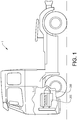
- a vehicle 1 with a transmission arrangement 200 and a prime mover 202.
- the transmission arrangement 200 comprises an assembly 100 ( Fig. 2 ) provided with a shaft 102 and a bearing arrangement 104 according to the present invention.
- the vehicle 1 depicted in Fig. 1 is a truck for which the inventive assembly 100 and bearing arrangement 104, as will be described further below, is particularly suitable for.
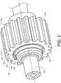
- Fig. 2 is a perspective view illustrating the assembly 100 comprising the shaft 102 and the bearing arrangement 104 according to an example embodiment.
- the assembly depicted in Fig. 2 further comprises a gear wheel 106.
- the gear wheel 106 comprises a plurality of gear teeth 108.
- the gear teeth 108 are in Fig. 2 depicted as straight gear teeth. It should however be readily understood that the gear teeth 108 may be helical such that the gear wheel 106 can sustain axial loads acting thereon.
- the gear wheel may also comprise clutch teeth (not shown) that are used in connection with an engaging sleeve (not shown) for connecting the gear wheel 106 to the shaft 102, or to other parts of the transmission 200.
- the assembly 100 comprises the bearing arrangement 104.
- the bearing arrangement 104 is thus arranged between the shaft 102 and the gear wheel 106.
- the bearing arrangement 104 comprises a bearing 105 provided with a plurality of cylindrical roller bearing elements 110 which are preferably arranged on a self-contained roller and cage assembly 112.
- cylindrical roller bearing elements Other types of rolling elements are of course conceivable such as e.g. tapered roller bearing elements, etc. However, for simplicity, the rolling elements will in the following be referred to as cylindrical roller bearing elements.
- the bearing arrangement 104 preferably comprises a bearing 105 with the inner ring integrated in the shaft 102 and the outer ring integrated in the gear wheel 106.
- the bearing arrangement 104 further comprises a ring shaped contact element 114.
- the ring shaped contact element 114 which will be described in further detail below, is arranged to abut an end surface of the rolling elements 110 when the bearing arrangement 104 is exposed to axial loading from e.g. mesh forces from the gear wheel 106.
- the ring shaped contact element 114 is arranged in axial connection with the protruding portion (403 in Fig. 4 ) of the shaft 102 or, as depicted in Fig. 2 , with a protruding portion of a contact ring 116 which is connected to the shaft 102.
- Figs. 3 and 4 are cross-sectional side views illustrating the assembly 100 and the bearing arrangement 104 in further detail.
- the assembly comprises the shaft 102 at which the bearing arrangement 104 is connected, which bearing arrangement 104 comprising the bearing 105, 105' and the ring shaped contact element 114, 114'.
- the assembly comprises a first 105 and a second bearing 105', wherein the first bearing 105 is arranged at a left hand side and the second bearing 105' is arranged at a right hand side as seen in the figures.
- the assembly comprises a first 114 and a second 114' ring shaped contact element arranged on the respective left and right hand sides.
- the bearings 105, 105' comprises a plurality of cylindrical roller bearing elements 110 which are arranged to roll against an inner 302 and an outer 304 raceway for the bearing arrangement 104.
- the inner raceway 302 is constituted by a portion of the circumferential surface of the shaft 102.
- the inner ring is integrated in the shaft 102.
- the outer raceway 304 on the other hand is constituted by a portion of a circumferential inner surface of the gear wheel 106.
- the outer bearing ring is thus integrated in the gear wheel 106.
- the bearing arrangement 104 and the gear wheel 106 are preferably assembled to the shaft 102 from the left hand side towards the right hand side as illustrated by the assembly direction 500.
- the assembly of the bearing arrangement 104 and the gear wheel 106 will be described in further detail below in relation to the description of Fig. 5 .
- the shaft 102 comprises a plurality of lubricating flow channels 306.
- the lubricating flow channels 306 are arranged to supply lubrication to the bearings 105, 105' and extends from a center portion 308 and radially towards a radially outer end surface 310 of the shaft 102.
- the lubricating flow channels 306 end in an opening 312 at the radially outer end surface 310 in the vicinity of the bearing arrangement 104.
- the lubricating flow channels may have an extension also in the axial direction thereof such that angled lubricating flow channels are obtained.
- Fig. 4 in which the ring shaped contact element is depicted in further detail.
- first ring shaped contact element 114 will be described. Specifics not described in relation to the first ring shaped contact element 114 will thereafter be described with reference to the second ring shaped contact element 114'.
- the ring shaped contact element 114 comprises a first contact surface 402 which is facing the end surfaces of the cylindrical roller bearing elements 110.
- the ring shaped contact element 114 thus has an extension in the axial direction from the first contact surface 402 to a second contact surface 404 arranged in abutment with a radially protruding portion 403 of the shaft 102, or as depicted in Fig. 4 , a radially protruding portion of a contact ring 116 which is connected to the shaft 102.
- the ring shaped contact element 114 further comprises a shaft connecting portion 408.
- the shaft connecting portion 408 is connected to the shaft 102, preferably by being press fitted to the shaft 102.
- the first ring shaped contact element 114 has an L-shaped form
- the second ring shaped contact element 114' has a straight form.
- the L-shaped form is suitable at positions where the contact area on the shaft 102 is arranged at a diameter which is equal to, or smaller than the diameter 412 of the inner raceway 302.
- the straight ring shaped contact element 114' is thus suitable to use where the contact area on the shaft 102 is arranged at a diameter which is larger than the diameter 412 of the inner raceway 302.
- the inner diameter of the shaft connecting portion 408 may be either equal to, or smaller than the diameter 412 of the inner raceway 302, or larger than the diameter 412 of the inner raceway 302, which is thus dependent on the geometries of the shaft 102.
- the ring shaped contact element 114 is positioned relative the inner raceway 302 in such a way that a continuous radial gap 414 is formed between the ring shaped contact element 114 and the inner raceway 302.
- the continuous radial gap 414 is formed by providing larger diameter 410 of the ring shaped contact element 114 at the axial position of the first contact surface 402 in comparison to the diameter 412 of the inner raceway 302.
- the opening 312 of the lubricating flow channel 306 is enclosed and a circumferential distribution channel 406 is formed.
- the circumferential distribution channel 406 extends continuously around the circumference of the inner raceway 302 for providing a continuous flow of lubrication to the bearing 105.
- the circumferential distribution channel 406 is also depicted in Fig. 5 .
- Fig. 5 illustrates an exploded perspective view for assembling the bearing arrangement 104 and the gear wheel 106 to the shaft 102.
- the bearing arrangement 104 and the gear wheel 106 are assembled from the left to the right as seen by the illustrated assembly direction 500.
- the second ring shaped contact element 114' is connected to the shaft 102 at a position located axially to the right of the right most raceway 302 of the shaft 102 as seen in Fig. 5 .
- the shaft connecting portion 408 of the second ring shaped contact element 114' is press fitted to the shaft 102.
- the diameter of the second ring shaped contact element 114' at the shaft connecting portion 408 is preferably larger than the diameter 412 of the raceway 302, and could be equal to the inner diameter 410 at the first contact surface 402.
- the second bearing 105' is connected to the shaft 102 at the right most raceway 302 of the shaft 102.
- the second bearing 105' is thus arranged to the shaft 102 such that the first contact surface 402 of the second ring shaped contact element 114' is positioned in the vicinity of the end surfaces of the cylindrical roller bearing elements 110.
- the gear wheel 106 is thereafter connected to the shaft 102 such that the second bearing 105' is enclosed between the shaft 102 and the gear wheel 106.
- the first bearing 105 is thereafter positioned between the shaft 102 and the gear wheel 106.
- the first bearing 105 is positioned at the left most raceway 302 of the shaft 102.
- the first ring shaped contact element 114 When the first bearing 105 is placed in its position, the first ring shaped contact element 114 is connected to the shaft 102. More particularly, the shaft connecting portion 408 of the first ring shaped contact element 114 is press fitted to the shaft 102.
- the diameter of the first ring shaped contact element 114 at the shaft connecting portion 408 is preferably equal to, or smaller than the diameter 412 of the raceway 302.
- the first contact surface 402 of the first ring shaped contact element 114 is positioned in the vicinity of the end surfaces of the cylindrical roller bearing elements 110.
- the contact ring 116 is connected to the shaft 102 such that a portion of the contact ring 116 is arranged in connection with the second contact surface 402 of the first ring shaped contact element 114.
Landscapes
- Engineering & Computer Science (AREA)
- General Engineering & Computer Science (AREA)
- Mechanical Engineering (AREA)
- Rolling Contact Bearings (AREA)
Claims (12)
- Ensemble palier (104) connectable à un arbre (102), l'ensemble palier (104) comprenant :- un palier (105, 105') comprenant une pluralité d'éléments roulants sous forme de roulements (110) conçus pour tourner par rapport à une piste intérieure (302) dudit ensemble palier ; et- un élément de contact de forme annulaire (114, 114') ayant une extension dans son sens axial, ledit élément de contact de forme annulaire (114, 114') comprenant en outre une première surface de contact (402) apte à faire face à la pluralité d'éléments roulants (110), la première surface de contact de l'élément de contact de forme annulaire étant conçue pour être en contact avec l'au moins un de la pluralité d'éléments roulants lorsque le palier est exposé à une charge axiale, un diamètre intérieur (410) de l'élément de contact de forme annulaire (114, 114') à la position axiale de la première surface de contact (402) ayant un diamètre supérieur à un diamètre (412) de ladite piste intérieure (302), de sorte qu'un intervalle radial continu (414) est créé dans le sens circonférentiel entre le premier élément de contact de forme annulaire (114, 114') et la piste intérieure (302) lorsque ledit ensemble palier (104) est connecté audit arbre (102), ledit intervalle radial (414) étant conçu pour être en communication fluidique avec un canal d'écoulement de lubrifiant (306) de l'arbre (102) lorsque ledit ensemble palier est connecté audit arbre, caractérisé en ce que la section de connexion d'arbre (408) de l'élément de contact de forme annulaire (114, 114') est connectée à l'arbre (102) lorsque l'ensemble palier (104) est connecté à l'arbre (102), la section de connexion d'arbre (408) de l'élément de contact de forme annulaire (114, 114') étant conçue pour être ajustée à la presse sur l'arbre (102).
- Ensemble palier (104) selon la revendication 1, dans lequel un diamètre intérieur de la section de connexion d'arbre (408) est inférieur ou égal au diamètre (412) de la piste intérieure (302).
- Ensemble palier (104) selon la revendication 1, dans lequel un diamètre intérieur de la section de connexion d'arbre (408) est supérieur au diamètre (412) de la piste inférieure (302).
- Ensemble palier (104) selon l'une quelconque des revendications 1 à 3, dans lequel la section de connexion d'arbre (408) est disposée à une extrémité axiale opposée de l'élément de contact de forme annulaire (114, 114') comparativement à la première surface de contact (402).
- Ensemble palier (104) selon l'une quelconque des revendications précédentes, dans lequel les éléments roulants (110) sont des éléments de palier à roulements cylindriques.
- Ensemble (100) comprenant :- un arbre (102) comprenant un canal d'écoulement de lubrifiant (306) disposé dans au moins un sens radial dans l'arbre (102) ; et- un ensemble palier (104) connecté à l'arbre (102), ledit ensemble palier (104) comprenant un palier (105, 105') comprenant une pluralité d'éléments roulants sous forme de roulements (110) conçus pour tourner par rapport à une piste intérieure (302) dudit ensemble palier (104) ; et- un élément de contact de forme annulaire (114, 114') ayant une extension dans son sens axial, ledit élément de contact de forme annulaire (114, 114') comprenant en outre une première surface de contact (402) faisant face à la pluralité d'éléments roulants (110), la première surface de contact de l'élément de contact de forme annulaire étant conçue pour être en contact avec l'au moins un de la pluralité d'éléments roulants lorsque le palier est exposé à une charge axiale, un diamètre intérieur (410) de l'élément de contact de forme annulaire (114, 114') à la position axiale de la première surface de contact (402) ayant un diamètre supérieur à un diamètre (412) de ladite piste intérieure (302), de sorte qu'un intervalle radial continu (414) est créé dans le sens circonférentiel entre le premier élément de contact de forme annulaire (114, 114') et la piste intérieure (302) lorsque ledit intervalle radial (414) est disposé en communication fluidique avec ledit canal d'écoulement de lubrifiant (306) de l'arbre (102), caractérisé en ce qu'une section de connexion d'arbre (408) de l'élément de contact de forme annulaire (114, 114') est connectée à l'arbre lorsque l'ensemble palier (104) est connecté à l'arbre (102), la section de connexion d'arbre (408) de l'élément de contact de forme annulaire (114, 114') étant conçue pour être ajustée à la presse sur l'arbre (102).
- Ensemble (100) selon la revendication 6, dans lequel l'élément de contact de forme annulaire (114, 114'), l'arbre (102) et les roulements (110) circonscrivent une ouverture (312) dudit canal d'écoulement de lubrifiant (306).
- Ensemble (100) selon l'une quelconque des revendications 6 à 7, dans lequel l'élément de contact de forme annulaire (114, 114') comprend une seconde surface de contact (404) disposée sur une face axialement opposée de l'élément de contact de forme annulaire (114, 114') comparativement à la première surface de contact (402), la seconde surface de contact (404) butant contre une section saillant radialement de l'arbre (403).
- Ensemble (100) selon l'une quelconque des revendications 6 à 8, dans lequel la piste intérieure (302) est formée par une section d'une surface circonférentielle dudit arbre (102).
- Procédé d'assemblage de l'ensemble palier (104) selon l'une quelconque des revendications 1 à 5 à un arbre (102), ce procédé comprenant les étapes suivantes :- connexion du palier (105, 105') à l'arbre (102) à une position axialement adjacente à une ouverture (312) d'un canal d'écoulement de lubrifiant (306) dudit arbre (102) ; et- connexion de l'élément de contact de forme annulaire (114, 114') à l'arbre de manière à ce qu'une section de l'élément de contact de forme annulaire (114, 114') soit positionnée radialement au-dessus de l'ouverture (312) du canal d'écoulement de lubrifiant (306) et de manière à ce qu'un intervalle radial (414) soit créé dans le sens circonférentiel entre l'élément de contact de forme annulaire (114, 114') et la piste intérieure (302).
- Dispositif de transmission (200) pour véhicule (1), le dispositif de transmission (200) comprenant un arbre (102) comprenant un canal d'écoulement de lubrifiant (306) disposé dans au moins un sens radial dans l'arbre ; et un ensemble palier (104) selon l'une quelconque des revendications 1 à 5.
- Véhicule (1) comprenant un dispositif de transmission (200), ledit dispositif de transmission (200) comprenant un arbre (102) comprenant un canal d'écoulement de lubrifiant (306) disposé dans au moins un sens radial dans l'arbre ; et un ensemble palier (104) selon l'une quelconque des revendications 1 à 5.
Applications Claiming Priority (1)
| Application Number | Priority Date | Filing Date | Title |
|---|---|---|---|
| PCT/EP2017/054040 WO2018153442A1 (fr) | 2017-02-22 | 2017-02-22 | Agencement de palier et ensemble comprenant un tel agencement de palier |
Publications (2)
| Publication Number | Publication Date |
|---|---|
| EP3586022A1 EP3586022A1 (fr) | 2020-01-01 |
| EP3586022B1 true EP3586022B1 (fr) | 2021-04-07 |
Family
ID=58098636
Family Applications (1)
| Application Number | Title | Priority Date | Filing Date |
|---|---|---|---|
| EP17706492.0A Active EP3586022B1 (fr) | 2017-02-22 | 2017-02-22 | Ensemble palier et système de palier comprenant une telle ensemble palier |
Country Status (4)
| Country | Link |
|---|---|
| US (1) | US11035457B2 (fr) |
| EP (1) | EP3586022B1 (fr) |
| CN (1) | CN110300860B (fr) |
| WO (1) | WO2018153442A1 (fr) |
Families Citing this family (2)
| Publication number | Priority date | Publication date | Assignee | Title |
|---|---|---|---|---|
| JP7616137B2 (ja) * | 2022-03-31 | 2025-01-17 | 株式会社アイシン | 車両用駆動装置 |
| CN114987729B (zh) * | 2022-05-30 | 2024-03-26 | 中国船舶重工集团公司第七一九研究所 | 集成电机推进装置及船舶 |
Citations (1)
| Publication number | Priority date | Publication date | Assignee | Title |
|---|---|---|---|---|
| US4319789A (en) * | 1980-03-13 | 1982-03-16 | Trw Inc. | Roller bearing and anti-skewing system therefor |
Family Cites Families (13)
| Publication number | Priority date | Publication date | Assignee | Title |
|---|---|---|---|---|
| DE520609C (de) * | 1926-07-11 | 1931-03-12 | Algemeene Octrooi Exploitatie | Eindeckerflugboot |
| US2029265A (en) * | 1934-05-30 | 1936-01-28 | Skf Svenska Kullagerfab Ab | Multirow cylindrical roller bearing |
| US4400040A (en) * | 1981-11-16 | 1983-08-23 | The Timken Company | Tapered roller bearing with improved lubricating means |
| JPS6196219A (ja) * | 1984-10-16 | 1986-05-14 | Ntn Toyo Bearing Co Ltd | 高速円筒ころ軸受 |
| US7448980B2 (en) * | 2005-05-09 | 2008-11-11 | Timken Us Corporation | Planetary gear assembly |
| JP2007024256A (ja) * | 2005-07-20 | 2007-02-01 | Ntn Corp | 転がり軸受の潤滑装置 |
| JP4800111B2 (ja) * | 2006-05-23 | 2011-10-26 | 三菱電機株式会社 | 電動機 |
| JP2012107694A (ja) * | 2010-11-17 | 2012-06-07 | Jtekt Corp | スラストころ軸受 |
| US8425361B1 (en) * | 2012-01-18 | 2013-04-23 | GM Global Technology Operations LLC | Lubrication system for a planetary gear set |
| CN202673973U (zh) * | 2012-07-10 | 2013-01-16 | 北京汽车动力总成有限公司 | 倒档轴内螺纹结构及汽车变速器 |
| DE102012216001B4 (de) * | 2012-09-10 | 2015-06-18 | Aktiebolaget Skf | Stift zum Führen eines Zahnrads und Planetengetriebe |
| DE102012219321A1 (de) * | 2012-10-23 | 2014-04-24 | Schaeffler Technologies Gmbh & Co. Kg | Wälzlager |
| JPWO2015076271A1 (ja) * | 2013-11-21 | 2017-03-16 | 日本精工株式会社 | 円筒ころ軸受及びトランスミッション用軸受装置 |
-
2017
- 2017-02-22 EP EP17706492.0A patent/EP3586022B1/fr active Active
- 2017-02-22 CN CN201780086656.1A patent/CN110300860B/zh active Active
- 2017-02-22 US US16/483,527 patent/US11035457B2/en active Active
- 2017-02-22 WO PCT/EP2017/054040 patent/WO2018153442A1/fr not_active Ceased
Patent Citations (1)
| Publication number | Priority date | Publication date | Assignee | Title |
|---|---|---|---|---|
| US4319789A (en) * | 1980-03-13 | 1982-03-16 | Trw Inc. | Roller bearing and anti-skewing system therefor |
Also Published As
| Publication number | Publication date |
|---|---|
| US20200116251A1 (en) | 2020-04-16 |
| EP3586022A1 (fr) | 2020-01-01 |
| CN110300860A (zh) | 2019-10-01 |
| US11035457B2 (en) | 2021-06-15 |
| CN110300860B (zh) | 2021-04-06 |
| WO2018153442A1 (fr) | 2018-08-30 |
Similar Documents
| Publication | Publication Date | Title |
|---|---|---|
| US7036989B2 (en) | Roller bearing oil feed device | |
| KR101439584B1 (ko) | 플라스틱 재료의 오버몰딩된 환형 바디를 포함한 베어링 조립체 | |
| US9267593B2 (en) | Planetary gear with a differential gear | |
| US10562350B2 (en) | Axle wheel end axial thrust assembly | |
| EP2615320A2 (fr) | Ensemble ajusteur de palier | |
| EP3929468B1 (fr) | Supports de moyeu de sortie pour un différentiel d'embrayage à fermeture bidirectionnel | |
| EP1777079A1 (fr) | Unite d'entrainment de roue | |
| JP6047999B2 (ja) | 回転支持装置 | |
| US20200049194A1 (en) | Sleeve for deep groove ball bearing | |
| CN101326376B (zh) | 轴承装置 | |
| EP3586022B1 (fr) | Ensemble palier et système de palier comprenant une telle ensemble palier | |
| US9115760B1 (en) | Tapered roller bearing | |
| WO2016040831A1 (fr) | Ensemble de poussée axiale d'extrémité de roue d'essieu | |
| US10166814B2 (en) | Axle wheel end axial thrust assembly | |
| WO2016040821A1 (fr) | Ensemble de poussée axiale d'extrémité de roue d'essieu | |
| US10166813B2 (en) | Axle wheel end axial thrust assembly | |
| EP0919739A3 (fr) | Cage pour palier à roulement | |
| CN216143058U (zh) | 齿轮箱的齿轮轴及包括该齿轮轴的齿轮箱 | |
| CN113646551B (zh) | 滚动轴承 | |
| KR102622836B1 (ko) | 차량용 휠베어링 | |
| JP5018546B2 (ja) | スライド式ラジアル転がり軸受 | |
| US20200271157A1 (en) | Transmission input shaft arrangement | |
| HK1226794A1 (en) | Extended length bearing cone system |
Legal Events
| Date | Code | Title | Description |
|---|---|---|---|
| STAA | Information on the status of an ep patent application or granted ep patent |
Free format text: STATUS: UNKNOWN |
|
| STAA | Information on the status of an ep patent application or granted ep patent |
Free format text: STATUS: THE INTERNATIONAL PUBLICATION HAS BEEN MADE |
|
| PUAI | Public reference made under article 153(3) epc to a published international application that has entered the european phase |
Free format text: ORIGINAL CODE: 0009012 |
|
| STAA | Information on the status of an ep patent application or granted ep patent |
Free format text: STATUS: REQUEST FOR EXAMINATION WAS MADE |
|
| 17P | Request for examination filed |
Effective date: 20190821 |
|
| AK | Designated contracting states |
Kind code of ref document: A1 Designated state(s): AL AT BE BG CH CY CZ DE DK EE ES FI FR GB GR HR HU IE IS IT LI LT LU LV MC MK MT NL NO PL PT RO RS SE SI SK SM TR |
|
| AX | Request for extension of the european patent |
Extension state: BA ME |
|
| DAV | Request for validation of the european patent (deleted) | ||
| DAX | Request for extension of the european patent (deleted) | ||
| REG | Reference to a national code |
Ref country code: DE Ref legal event code: R079 Ref document number: 602017036113 Country of ref document: DE Free format text: PREVIOUS MAIN CLASS: F16C0033660000 Ipc: F16C0025060000 |
|
| RIC1 | Information provided on ipc code assigned before grant |
Ipc: F16C 25/06 20060101AFI20200924BHEP Ipc: F16C 33/58 20060101ALI20200924BHEP Ipc: F16C 33/34 20060101ALN20200924BHEP |
|
| GRAP | Despatch of communication of intention to grant a patent |
Free format text: ORIGINAL CODE: EPIDOSNIGR1 |
|
| RIC1 | Information provided on ipc code assigned before grant |
Ipc: F16C 33/34 20060101ALN20200929BHEP Ipc: F16C 33/58 20060101ALI20200929BHEP Ipc: F16C 25/06 20060101AFI20200929BHEP |
|
| STAA | Information on the status of an ep patent application or granted ep patent |
Free format text: STATUS: GRANT OF PATENT IS INTENDED |
|
| INTG | Intention to grant announced |
Effective date: 20201105 |
|
| GRAS | Grant fee paid |
Free format text: ORIGINAL CODE: EPIDOSNIGR3 |
|
| GRAA | (expected) grant |
Free format text: ORIGINAL CODE: 0009210 |
|
| STAA | Information on the status of an ep patent application or granted ep patent |
Free format text: STATUS: THE PATENT HAS BEEN GRANTED |
|
| AK | Designated contracting states |
Kind code of ref document: B1 Designated state(s): AL AT BE BG CH CY CZ DE DK EE ES FI FR GB GR HR HU IE IS IT LI LT LU LV MC MK MT NL NO PL PT RO RS SE SI SK SM TR |
|
| REG | Reference to a national code |
Ref country code: GB Ref legal event code: FG4D |
|
| REG | Reference to a national code |
Ref country code: CH Ref legal event code: EP Ref country code: AT Ref legal event code: REF Ref document number: 1380056 Country of ref document: AT Kind code of ref document: T Effective date: 20210415 |
|
| REG | Reference to a national code |
Ref country code: DE Ref legal event code: R096 Ref document number: 602017036113 Country of ref document: DE |
|
| REG | Reference to a national code |
Ref country code: IE Ref legal event code: FG4D |
|
| REG | Reference to a national code |
Ref country code: SE Ref legal event code: TRGR |
|
| REG | Reference to a national code |
Ref country code: NL Ref legal event code: FP |
|
| REG | Reference to a national code |
Ref country code: LT Ref legal event code: MG9D |
|
| REG | Reference to a national code |
Ref country code: AT Ref legal event code: MK05 Ref document number: 1380056 Country of ref document: AT Kind code of ref document: T Effective date: 20210407 |
|
| PG25 | Lapsed in a contracting state [announced via postgrant information from national office to epo] |
Ref country code: HR Free format text: LAPSE BECAUSE OF FAILURE TO SUBMIT A TRANSLATION OF THE DESCRIPTION OR TO PAY THE FEE WITHIN THE PRESCRIBED TIME-LIMIT Effective date: 20210407 Ref country code: BG Free format text: LAPSE BECAUSE OF FAILURE TO SUBMIT A TRANSLATION OF THE DESCRIPTION OR TO PAY THE FEE WITHIN THE PRESCRIBED TIME-LIMIT Effective date: 20210707 Ref country code: AT Free format text: LAPSE BECAUSE OF FAILURE TO SUBMIT A TRANSLATION OF THE DESCRIPTION OR TO PAY THE FEE WITHIN THE PRESCRIBED TIME-LIMIT Effective date: 20210407 Ref country code: FI Free format text: LAPSE BECAUSE OF FAILURE TO SUBMIT A TRANSLATION OF THE DESCRIPTION OR TO PAY THE FEE WITHIN THE PRESCRIBED TIME-LIMIT Effective date: 20210407 Ref country code: LT Free format text: LAPSE BECAUSE OF FAILURE TO SUBMIT A TRANSLATION OF THE DESCRIPTION OR TO PAY THE FEE WITHIN THE PRESCRIBED TIME-LIMIT Effective date: 20210407 |
|
| PG25 | Lapsed in a contracting state [announced via postgrant information from national office to epo] |
Ref country code: RS Free format text: LAPSE BECAUSE OF FAILURE TO SUBMIT A TRANSLATION OF THE DESCRIPTION OR TO PAY THE FEE WITHIN THE PRESCRIBED TIME-LIMIT Effective date: 20210407 Ref country code: PT Free format text: LAPSE BECAUSE OF FAILURE TO SUBMIT A TRANSLATION OF THE DESCRIPTION OR TO PAY THE FEE WITHIN THE PRESCRIBED TIME-LIMIT Effective date: 20210809 Ref country code: PL Free format text: LAPSE BECAUSE OF FAILURE TO SUBMIT A TRANSLATION OF THE DESCRIPTION OR TO PAY THE FEE WITHIN THE PRESCRIBED TIME-LIMIT Effective date: 20210407 Ref country code: NO Free format text: LAPSE BECAUSE OF FAILURE TO SUBMIT A TRANSLATION OF THE DESCRIPTION OR TO PAY THE FEE WITHIN THE PRESCRIBED TIME-LIMIT Effective date: 20210707 Ref country code: LV Free format text: LAPSE BECAUSE OF FAILURE TO SUBMIT A TRANSLATION OF THE DESCRIPTION OR TO PAY THE FEE WITHIN THE PRESCRIBED TIME-LIMIT Effective date: 20210407 Ref country code: GR Free format text: LAPSE BECAUSE OF FAILURE TO SUBMIT A TRANSLATION OF THE DESCRIPTION OR TO PAY THE FEE WITHIN THE PRESCRIBED TIME-LIMIT Effective date: 20210708 Ref country code: IS Free format text: LAPSE BECAUSE OF FAILURE TO SUBMIT A TRANSLATION OF THE DESCRIPTION OR TO PAY THE FEE WITHIN THE PRESCRIBED TIME-LIMIT Effective date: 20210807 |
|
| REG | Reference to a national code |
Ref country code: DE Ref legal event code: R097 Ref document number: 602017036113 Country of ref document: DE |
|
| PG25 | Lapsed in a contracting state [announced via postgrant information from national office to epo] |
Ref country code: EE Free format text: LAPSE BECAUSE OF FAILURE TO SUBMIT A TRANSLATION OF THE DESCRIPTION OR TO PAY THE FEE WITHIN THE PRESCRIBED TIME-LIMIT Effective date: 20210407 Ref country code: DK Free format text: LAPSE BECAUSE OF FAILURE TO SUBMIT A TRANSLATION OF THE DESCRIPTION OR TO PAY THE FEE WITHIN THE PRESCRIBED TIME-LIMIT Effective date: 20210407 Ref country code: CZ Free format text: LAPSE BECAUSE OF FAILURE TO SUBMIT A TRANSLATION OF THE DESCRIPTION OR TO PAY THE FEE WITHIN THE PRESCRIBED TIME-LIMIT Effective date: 20210407 Ref country code: ES Free format text: LAPSE BECAUSE OF FAILURE TO SUBMIT A TRANSLATION OF THE DESCRIPTION OR TO PAY THE FEE WITHIN THE PRESCRIBED TIME-LIMIT Effective date: 20210407 Ref country code: RO Free format text: LAPSE BECAUSE OF FAILURE TO SUBMIT A TRANSLATION OF THE DESCRIPTION OR TO PAY THE FEE WITHIN THE PRESCRIBED TIME-LIMIT Effective date: 20210407 Ref country code: SK Free format text: LAPSE BECAUSE OF FAILURE TO SUBMIT A TRANSLATION OF THE DESCRIPTION OR TO PAY THE FEE WITHIN THE PRESCRIBED TIME-LIMIT Effective date: 20210407 Ref country code: SM Free format text: LAPSE BECAUSE OF FAILURE TO SUBMIT A TRANSLATION OF THE DESCRIPTION OR TO PAY THE FEE WITHIN THE PRESCRIBED TIME-LIMIT Effective date: 20210407 |
|
| PLBE | No opposition filed within time limit |
Free format text: ORIGINAL CODE: 0009261 |
|
| STAA | Information on the status of an ep patent application or granted ep patent |
Free format text: STATUS: NO OPPOSITION FILED WITHIN TIME LIMIT |
|
| 26N | No opposition filed |
Effective date: 20220110 |
|
| PG25 | Lapsed in a contracting state [announced via postgrant information from national office to epo] |
Ref country code: IS Free format text: LAPSE BECAUSE OF FAILURE TO SUBMIT A TRANSLATION OF THE DESCRIPTION OR TO PAY THE FEE WITHIN THE PRESCRIBED TIME-LIMIT Effective date: 20210807 Ref country code: AL Free format text: LAPSE BECAUSE OF FAILURE TO SUBMIT A TRANSLATION OF THE DESCRIPTION OR TO PAY THE FEE WITHIN THE PRESCRIBED TIME-LIMIT Effective date: 20210407 |
|
| PG25 | Lapsed in a contracting state [announced via postgrant information from national office to epo] |
Ref country code: IT Free format text: LAPSE BECAUSE OF FAILURE TO SUBMIT A TRANSLATION OF THE DESCRIPTION OR TO PAY THE FEE WITHIN THE PRESCRIBED TIME-LIMIT Effective date: 20210407 |
|
| PG25 | Lapsed in a contracting state [announced via postgrant information from national office to epo] |
Ref country code: MC Free format text: LAPSE BECAUSE OF FAILURE TO SUBMIT A TRANSLATION OF THE DESCRIPTION OR TO PAY THE FEE WITHIN THE PRESCRIBED TIME-LIMIT Effective date: 20210407 |
|
| REG | Reference to a national code |
Ref country code: CH Ref legal event code: PL |
|
| REG | Reference to a national code |
Ref country code: BE Ref legal event code: MM Effective date: 20220228 |
|
| GBPC | Gb: european patent ceased through non-payment of renewal fee |
Effective date: 20220222 |
|
| PG25 | Lapsed in a contracting state [announced via postgrant information from national office to epo] |
Ref country code: LU Free format text: LAPSE BECAUSE OF NON-PAYMENT OF DUE FEES Effective date: 20220222 |
|
| PG25 | Lapsed in a contracting state [announced via postgrant information from national office to epo] |
Ref country code: LI Free format text: LAPSE BECAUSE OF NON-PAYMENT OF DUE FEES Effective date: 20220228 Ref country code: IE Free format text: LAPSE BECAUSE OF NON-PAYMENT OF DUE FEES Effective date: 20220222 Ref country code: GB Free format text: LAPSE BECAUSE OF NON-PAYMENT OF DUE FEES Effective date: 20220222 Ref country code: CH Free format text: LAPSE BECAUSE OF NON-PAYMENT OF DUE FEES Effective date: 20220228 |
|
| PG25 | Lapsed in a contracting state [announced via postgrant information from national office to epo] |
Ref country code: BE Free format text: LAPSE BECAUSE OF NON-PAYMENT OF DUE FEES Effective date: 20220228 |
|
| PGFP | Annual fee paid to national office [announced via postgrant information from national office to epo] |
Ref country code: NL Payment date: 20240226 Year of fee payment: 8 |
|
| PG25 | Lapsed in a contracting state [announced via postgrant information from national office to epo] |
Ref country code: MK Free format text: LAPSE BECAUSE OF FAILURE TO SUBMIT A TRANSLATION OF THE DESCRIPTION OR TO PAY THE FEE WITHIN THE PRESCRIBED TIME-LIMIT Effective date: 20210407 Ref country code: CY Free format text: LAPSE BECAUSE OF FAILURE TO SUBMIT A TRANSLATION OF THE DESCRIPTION OR TO PAY THE FEE WITHIN THE PRESCRIBED TIME-LIMIT Effective date: 20210407 |
|
| PG25 | Lapsed in a contracting state [announced via postgrant information from national office to epo] |
Ref country code: HU Free format text: LAPSE BECAUSE OF FAILURE TO SUBMIT A TRANSLATION OF THE DESCRIPTION OR TO PAY THE FEE WITHIN THE PRESCRIBED TIME-LIMIT; INVALID AB INITIO Effective date: 20170222 |
|
| PGFP | Annual fee paid to national office [announced via postgrant information from national office to epo] |
Ref country code: SE Payment date: 20240226 Year of fee payment: 8 Ref country code: FR Payment date: 20240226 Year of fee payment: 8 |
|
| PG25 | Lapsed in a contracting state [announced via postgrant information from national office to epo] |
Ref country code: MT Free format text: LAPSE BECAUSE OF FAILURE TO SUBMIT A TRANSLATION OF THE DESCRIPTION OR TO PAY THE FEE WITHIN THE PRESCRIBED TIME-LIMIT Effective date: 20210407 |
|
| REG | Reference to a national code |
Ref country code: SE Ref legal event code: EUG |
|
| REG | Reference to a national code |
Ref country code: NL Ref legal event code: MM Effective date: 20250301 |
|
| PG25 | Lapsed in a contracting state [announced via postgrant information from national office to epo] |
Ref country code: NL Free format text: LAPSE BECAUSE OF NON-PAYMENT OF DUE FEES Effective date: 20250301 |
|
| PG25 | Lapsed in a contracting state [announced via postgrant information from national office to epo] |
Ref country code: TR Free format text: LAPSE BECAUSE OF FAILURE TO SUBMIT A TRANSLATION OF THE DESCRIPTION OR TO PAY THE FEE WITHIN THE PRESCRIBED TIME-LIMIT Effective date: 20210407 |
|
| PG25 | Lapsed in a contracting state [announced via postgrant information from national office to epo] |
Ref country code: FR Free format text: LAPSE BECAUSE OF NON-PAYMENT OF DUE FEES Effective date: 20250228 |
|
| PGFP | Annual fee paid to national office [announced via postgrant information from national office to epo] |
Ref country code: DE Payment date: 20260220 Year of fee payment: 10 |