EP3586451B1 - Appareil pour configurer des faisceaux de signaux de référence sur la base d'une précision de localisation d'équipement utilisateur - Google Patents
Appareil pour configurer des faisceaux de signaux de référence sur la base d'une précision de localisation d'équipement utilisateur Download PDFInfo
- Publication number
- EP3586451B1 EP3586451B1 EP17713206.5A EP17713206A EP3586451B1 EP 3586451 B1 EP3586451 B1 EP 3586451B1 EP 17713206 A EP17713206 A EP 17713206A EP 3586451 B1 EP3586451 B1 EP 3586451B1
- Authority
- EP
- European Patent Office
- Prior art keywords
- determined
- value
- accuracy
- localization
- network node
- Prior art date
- Legal status (The legal status is an assumption and is not a legal conclusion. Google has not performed a legal analysis and makes no representation as to the accuracy of the status listed.)
- Active
Links
Images



Classifications
-
- H—ELECTRICITY
- H04—ELECTRIC COMMUNICATION TECHNIQUE
- H04B—TRANSMISSION
- H04B7/00—Radio transmission systems, i.e. using radiation field
- H04B7/02—Diversity systems; Multi-antenna system, i.e. transmission or reception using multiple antennas
- H04B7/04—Diversity systems; Multi-antenna system, i.e. transmission or reception using multiple antennas using two or more spaced independent antennas
- H04B7/06—Diversity systems; Multi-antenna system, i.e. transmission or reception using multiple antennas using two or more spaced independent antennas at the transmitting station
- H04B7/0613—Diversity systems; Multi-antenna system, i.e. transmission or reception using multiple antennas using two or more spaced independent antennas at the transmitting station using simultaneous transmission
- H04B7/0615—Diversity systems; Multi-antenna system, i.e. transmission or reception using multiple antennas using two or more spaced independent antennas at the transmitting station using simultaneous transmission of weighted versions of same signal
- H04B7/0619—Diversity systems; Multi-antenna system, i.e. transmission or reception using multiple antennas using two or more spaced independent antennas at the transmitting station using simultaneous transmission of weighted versions of same signal using feedback from receiving side
- H04B7/0658—Feedback reduction
- H04B7/066—Combined feedback for a number of channels, e.g. over several subcarriers like in orthogonal frequency division multiplexing [OFDM]
-
- G—PHYSICS
- G01—MEASURING; TESTING
- G01S—RADIO DIRECTION-FINDING; RADIO NAVIGATION; DETERMINING DISTANCE OR VELOCITY BY USE OF RADIO WAVES; LOCATING OR PRESENCE-DETECTING BY USE OF THE REFLECTION OR RERADIATION OF RADIO WAVES; ANALOGOUS ARRANGEMENTS USING OTHER WAVES
- G01S3/00—Direction-finders for determining the direction from which infrasonic, sonic, ultrasonic or electromagnetic waves, or particle emission, not having a directional significance, are being received
- G01S3/02—Direction-finders for determining the direction from which infrasonic, sonic, ultrasonic or electromagnetic waves, or particle emission, not having a directional significance, are being received using radio waves
- G01S3/74—Multi-channel systems specially adapted for direction-finding, i.e. having a single antenna system capable of giving simultaneous indications of the directions of different signals
-
- G—PHYSICS
- G01—MEASURING; TESTING
- G01S—RADIO DIRECTION-FINDING; RADIO NAVIGATION; DETERMINING DISTANCE OR VELOCITY BY USE OF RADIO WAVES; LOCATING OR PRESENCE-DETECTING BY USE OF THE REFLECTION OR RERADIATION OF RADIO WAVES; ANALOGOUS ARRANGEMENTS USING OTHER WAVES
- G01S5/00—Position-fixing by co-ordinating two or more direction or position line determinations; Position-fixing by co-ordinating two or more distance determinations
- G01S5/0009—Transmission of position information to remote stations
- G01S5/0018—Transmission from mobile station to base station
- G01S5/0036—Transmission from mobile station to base station of measured values, i.e. measurement on mobile and position calculation on base station
-
- G—PHYSICS
- G01—MEASURING; TESTING
- G01S—RADIO DIRECTION-FINDING; RADIO NAVIGATION; DETERMINING DISTANCE OR VELOCITY BY USE OF RADIO WAVES; LOCATING OR PRESENCE-DETECTING BY USE OF THE REFLECTION OR RERADIATION OF RADIO WAVES; ANALOGOUS ARRANGEMENTS USING OTHER WAVES
- G01S5/00—Position-fixing by co-ordinating two or more direction or position line determinations; Position-fixing by co-ordinating two or more distance determinations
- G01S5/02—Position-fixing by co-ordinating two or more direction or position line determinations; Position-fixing by co-ordinating two or more distance determinations using radio waves
- G01S5/0257—Hybrid positioning
- G01S5/0268—Hybrid positioning by deriving positions from different combinations of signals or of estimated positions in a single positioning system
-
- G—PHYSICS
- G01—MEASURING; TESTING
- G01S—RADIO DIRECTION-FINDING; RADIO NAVIGATION; DETERMINING DISTANCE OR VELOCITY BY USE OF RADIO WAVES; LOCATING OR PRESENCE-DETECTING BY USE OF THE REFLECTION OR RERADIATION OF RADIO WAVES; ANALOGOUS ARRANGEMENTS USING OTHER WAVES
- G01S5/00—Position-fixing by co-ordinating two or more direction or position line determinations; Position-fixing by co-ordinating two or more distance determinations
- G01S5/02—Position-fixing by co-ordinating two or more direction or position line determinations; Position-fixing by co-ordinating two or more distance determinations using radio waves
- G01S5/0273—Position-fixing by co-ordinating two or more direction or position line determinations; Position-fixing by co-ordinating two or more distance determinations using radio waves using multipath or indirect path propagation signals in position determination
-
- H—ELECTRICITY
- H04—ELECTRIC COMMUNICATION TECHNIQUE
- H04B—TRANSMISSION
- H04B7/00—Radio transmission systems, i.e. using radiation field
- H04B7/02—Diversity systems; Multi-antenna system, i.e. transmission or reception using multiple antennas
- H04B7/04—Diversity systems; Multi-antenna system, i.e. transmission or reception using multiple antennas using two or more spaced independent antennas
- H04B7/06—Diversity systems; Multi-antenna system, i.e. transmission or reception using multiple antennas using two or more spaced independent antennas at the transmitting station
- H04B7/0613—Diversity systems; Multi-antenna system, i.e. transmission or reception using multiple antennas using two or more spaced independent antennas at the transmitting station using simultaneous transmission
- H04B7/0615—Diversity systems; Multi-antenna system, i.e. transmission or reception using multiple antennas using two or more spaced independent antennas at the transmitting station using simultaneous transmission of weighted versions of same signal
- H04B7/0617—Diversity systems; Multi-antenna system, i.e. transmission or reception using multiple antennas using two or more spaced independent antennas at the transmitting station using simultaneous transmission of weighted versions of same signal for beam forming
-
- H—ELECTRICITY
- H04—ELECTRIC COMMUNICATION TECHNIQUE
- H04B—TRANSMISSION
- H04B7/00—Radio transmission systems, i.e. using radiation field
- H04B7/02—Diversity systems; Multi-antenna system, i.e. transmission or reception using multiple antennas
- H04B7/04—Diversity systems; Multi-antenna system, i.e. transmission or reception using multiple antennas using two or more spaced independent antennas
- H04B7/06—Diversity systems; Multi-antenna system, i.e. transmission or reception using multiple antennas using two or more spaced independent antennas at the transmitting station
- H04B7/0613—Diversity systems; Multi-antenna system, i.e. transmission or reception using multiple antennas using two or more spaced independent antennas at the transmitting station using simultaneous transmission
- H04B7/0615—Diversity systems; Multi-antenna system, i.e. transmission or reception using multiple antennas using two or more spaced independent antennas at the transmitting station using simultaneous transmission of weighted versions of same signal
- H04B7/0619—Diversity systems; Multi-antenna system, i.e. transmission or reception using multiple antennas using two or more spaced independent antennas at the transmitting station using simultaneous transmission of weighted versions of same signal using feedback from receiving side
- H04B7/0621—Feedback content
- H04B7/0623—Auxiliary parameters, e.g. power control [PCB] or not acknowledged commands [NACK], used as feedback information
-
- H—ELECTRICITY
- H04—ELECTRIC COMMUNICATION TECHNIQUE
- H04W—WIRELESS COMMUNICATION NETWORKS
- H04W64/00—Locating users or terminals or network equipment for network management purposes, e.g. mobility management
- H04W64/006—Locating users or terminals or network equipment for network management purposes, e.g. mobility management with additional information processing, e.g. for direction or speed determination
Definitions
- the aspects of the present disclosure relate generally to wireless communication systems and more particularly to localization of a user node by a network node in a wireless communication system.
- low frequency radio and high frequency radio are considered to be used for the purpose of establishing access links between access nodes (also access points, base stations, or Node B or eNode B/eNB) and user nodes (also user devices, user equipment/UE, mobile terminals, or mobile device) within a wireless access network.
- access nodes also access points, base stations, or Node B or eNode B/eNB
- user nodes also user devices, user equipment/UE, mobile terminals, or mobile device
- the high frequency band can be in the range of approximately to and including 30GHz to 60GHz
- low frequency band can be in the range of approximately to and including 3GHz to 4GHz.
- the large available bandwidth and high gain narrow antenna beam make high frequency links very suitable to provide very high data throughput between access nodes and user nodes.
- high frequency links are more subject to blockage due to building walls, vehicles and foliage in a varying environment than those of low frequency. It is important for the user equipment to maintain the best transmission beam direction for the transmitter, best reception beam direction for the receiver and best beam-pair for the transmitter and receiver when both are using narrow beams.
- the localization of the user node as well as the determination of the optimal antenna beam direction for both the access node and user node can benefit from the combined usage of high frequency and low frequency links.
- low frequency links can have relatively wider antenna beam widths and can be used to provide coarse localization of the user node before the more accurate localization is done with the high frequency link.
- the low frequency link can also be used for control messages and signalling between the access node and the user node, and to help the localization and beam alignment on the high frequency link.
- US 2016/020876 A1 discloses methods for low-frequency assisted beamforming in millimeter wave access systems.
- WO 99/57574 A1 discloses methods for Direction of Arrival (DoA) estimation, wherein the rate of change of the estimated DoA is disclosed as a measure of the reliability of the estimated DoA.
- WO 2017/028875 A1 and US 2014/148107 A1 disclose further aspects in respect of low-frequency assisted millimeter wave beamforming systems.
- the quantity of beams will have impact on many system performance aspects including the network resource usage, the user node resource usage as well as the time needed to finish user node localization on high frequency.
- a network node for a wireless communication system.
- the network node is configured to localize a user node in a first localization operation carried out at a first frequency; determine an accuracy value associated with the first localization operation and adjust at least one beam parameter for radio beams to be used in a second localization operation based on the determined accuracy value.
- the second localization operation is carried out at a second frequency that is greater than the first frequency.
- the network node is configured to determine the accuracy value during the first localization operation by tracking a rate of change of an angle of a radio beacon signal transmitted from the user node.
- a first value is assigned to the accuracy value, the first value being lower than a previous accuracy value. If the rate of change is less than the pre-determined value a second value is assigned to the accuracy value, the second value being higher than a previous accuracy value. Since the parameters, including but not limited to the number of beams and/or the width of beams, will have impact on the network resource usage, the performance of localization at a second frequency and the interference within the network, controlling those parameters carefully and adaptively will have benefits for abovementioned aspects. For example, when a fewer number of beams are used for the localization at a second frequency, the used radio resource and caused interference will be less.
- the aspects of the disclosed embodiments configure the high frequency beams of a reference signal based on the accuracy of the user node localization on low frequency in order to achieve beam alignment in high frequency with an optimal resource usage.
- the network node is further configured to receive a movement measurement value from the user node, the movement measurement value being based on one or more of a change in location of the user node or a change in orientation of the user node.
- the movement measurement value is compared to a pre-determined movement measurement value and the determined accuracy value is adjusted based on the comparison.
- the configuration of beams needed for the high frequency localization can be optimized based on the accuracy of the low frequency localization of the user node.
- the movement measurement value is used to assist the network node to determine the low frequency localization accuracy value, based on for example measurements done by the user node using internal sensors.
- the network node is configured to adjust the at least one beam parameter for radio beams to be used in the second localization by adjusting a number of radio beams and a beam width of the radio beams to be used for the second localization operation; and send the determined configuration of radio beams for the second localization operation to the user node.
- Optimizing the number of beams and the width of the beams improves resource usage in the second, high frequency localization, since more beams increases the energy used and adds more complexity and cost.
- the width of the beams impacts the interference and coverage of a network. A larger beam width and be used to increase the coverage of the network node.
- the network node is configured to localize the user node in the second localization operation by decreasing the number of radio beams for the second localization operation from a pre-determined number of radio beams when the determined accuracy value is greater than a pre-determined accuracy threshold value and increasing the number of radio beams in for the second localization operation from the pre-determined number of radio beams when the determined accuracy value is less than the pre-determined accuracy threshold value.
- the network node has had an accurate localization on the first frequency, less beams are needed for the second localization on the second frequency. The user node will need to measure and report less number of beams, which improves energy consumption and localization latency.
- the network node is configured to decrease the beam width of the radio beams from a pre-determined beam width when the determined accuracy value is greater than the pre-determined accuracy threshold value and increase the beam width of the radio beams from the pre-determined beam width when the determined accuracy value is less than the pre-determined accuracy threshold value.
- the network node is configured to adjust the number of beams independently of adjusting the beam width of the beam pattern of the radio beams in the set of radio beams.
- the network node is configured to track the rate of change of the angle of the radio beacon signal transmitted from the user node relative to the network node by determining an angle of arrival of the radio beacon signal, comparing the determined angle to a previously determined angle of arrival; and determining the rate of change of the angle of the radio beacon signal based on the comparison. Tracking the angle of arrival of the radio beacon signal is used to assist the network node to determine the low frequency localization accuracy value, based on for example measurements done by the user node using internal sensors.
- a user node in a wireless communication system is configured to determine a movement measurement value of the user node, the movement measurement value being based on one or more of a change in location and a change in orientation of the user node; transmit the movement measurement value to the network node; receive information on a configuration of radio beams for be used for a second localization operation of the user node, the configuration of radio beams being based on the determined movement measurement value; and use the radio beams for either transmission or reception in the second localization operation of the user node.
- the beam configuration for the high frequency localization phase can be optimized with knowledge of the accuracy of the low frequency localization, which improves resource usage and system performance.
- the user node is configured to obtain measurement data for one or more of the change in location and orientation of the user node from internal sensors, compare the obtained measurement data to pre-determined thresholds, and determine the movement measurement value based on the comparison.
- the number of beams and the beam width of the beams can be optimized.
- the method comprises localizing a user node in a first localization operation carried out at a first frequency; determining an accuracy value associated with the first localization operation; adjusting at least one beam parameter for radio beams to be used in a second localization operation based on the determined accuracy value, the second localization operation carried out at a second frequency that is greater than the first frequency; and determining the accuracy value associated with the first localization operation by: tracking a rate of change of an angle of a radio beacon signal transmitted from the user node relative to the network node; and if the rate of change of the angle exceeds a pre-determined value assigning a first value to the accuracy value, the first value being lower than a previous accuracy value and if the rate of change is less than the pre-determined value assigning a second value to the accuracy value, the second value being higher than a previous accuracy value.
- the aspects of the disclosed embodiments configure the high frequency beams of a reference signal based on the accuracy
- the method further includes receiving a movement measurement value from the user node, the movement measurement value being based on one or more of a change in location of the user node or a change in orientation of the user node; comparing the movement measurement value to a pre-determined movement measurement value; and adjusting the determined accuracy value based on the comparison.
- the configuration of beams needed for the high frequency localization can be optimized based on the accuracy of the low frequency localization of the user node.
- the movement measurement value is used to assist the network node to determine the low frequency localization accuracy value, based on for example measurements done by the user node using internal sensors.
- the method includes adjusting the at least one beam parameter for radio beams to be used in the second localization by adjusting a number of radio beams and a beam width of the radio beams to be used for the second localization operation; and sending the determined configuration of radio beams for the second localization operation to the user node.
- Optimizing the number of beams and the width of the beams improves resource usage in the second, high frequency localization, since more beams increases the energy used and adds more complexity and cost.
- the width of the beams impacts the interference and coverage of a network. A larger beam width and be used to increase the coverage of the network node.
- the method includes decreasing the number of radio beams for the second localization operation from a pre-determined number of radio beams when it is determined that the accuracy value is greater than a pre-determined accuracy threshold value and increasing the number of radio beams in for the second localization operation from the pre-determined number of radio beams when it is determined that the accuracy value is less than the pre-determined accuracy threshold value.
- the method includes decreasing the beam width of the radio beams from a pre-determined beam width when it is determined that the accuracy value is greater than the pre-determined accuracy threshold value and increasing the beam width of the radio beams from the pre-determined beam width when it is determined that the accuracy value is less than the pre-determined accuracy threshold value.
- the method includes tracking the rate of change of the angle of the radio beacon signal transmitted from the user node relative to the network node by determining an angle of arrival of the radio beacon signal, comparing the determined angle to a previously determined angle of arrival; and determining the rate of change of the angle of the radio beacon signal based on the comparison. Tracking the angle of arrival of the radio beacon signal is used to assist the network node to determine the low frequency localization accuracy value, based on for example measurements done by the user node using internal sensors.
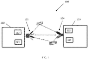
- FIG. 1 there can be seen an exemplary block diagram of a wireless communication system 100 incorporating aspects of the disclosed embodiments.
- the aspects of the disclosed embodiments are directed to configuring the high frequency beams of a reference signal based on a determined accuracy of the user equipment localization on low frequency.
- the wireless communication system 100 includes at least one network node 110 and at least one user node 120.
- the wireless communication system 100 can be any suitable type of wireless communication system, such as for example, but not limited to LTE, 5G or new radio (NR).
- the network node 110 can generally comprise or include a network node such as an Evolved Universal Terrestrial Radio Access Network (E-UTRAN) NodeB or evolved NodeB (eNB).
- E-UTRAN Evolved Universal Terrestrial Radio Access Network
- eNB evolved NodeB
- the network node 110 may also be referred to as an access point or base station.
- the user node 120 can generally comprise or include one or more of a user equipment (UE), a mobile terminal, mobile device or communication apparatus, for example.
- UE user equipment
- the aspects of the disclosed embodiments generally include the determination of the low frequency (LF) localization accuracy of the user node 110, a determination of beam parameters for beams used for transmission and/or reception, and the transfer of such determination information through specific signalling.
- the number of high frequency (HF) beams and the beam width of such high frequency beams can also be adjusted.
- the higher the accuracy of the low frequency localization the narrower the high frequency beam width may need to be.
- the lower the accuracy of the low frequency localization the wider the high frequency beam width may need to be.
- the adjustment of number of beams and the adjustment of beam width can be done independently, also can be done jointly.
- the network node 110 is configured to localize a user node 120 in a first localization operation.
- the first localization operation is carried out at a first frequency, such as a low frequency.
- the network node 110 is configured to localize the user node 120 in the first localization with a low frequency link based on downlink measurement.
- the network node 110 transmits one or more reference signals to the user node 120.
- the user node 120 measures the one or more references signals and detects the strongest reference signal or signals.
- the user node 120 can transmit the results of the measurements, such as by transmitting an identifier associated with the strongest reference signal or signals, back to the network node 110.
- the network node 110 can select the radio beams based on the received measurement results for the second localization.
- the network node 110 receives reference signals or radio beacon signals that are transmitted by the user node 120.
- the network node 110 measures the received uplink reference signals or radio beacons to determine the radio beams to be used for the second localization.
- the network node 110 is further configured to determine an accuracy value associated with the first localization. Based on the determined accuracy value, the network node 110 is configured to adjust at least one beam parameter for radio beams to be used in a second localization operation.
- the second localization operation is carried out at a second frequency, where the second frequency is greater than the first frequency. Generally, the second frequency is in the high frequency range.
- the network node 110 is configured to determine the accuracy value associated with the first localization operation by tracking a rate of change of an angle of a radio beam signal transmitted from the user node 120 relative to the network node 110, also referred to as an uplink signal or radio beam. If the rate of change of the angle exceeds a pre-determined value, a first value can be assigned to the accuracy value, the first value being lower than a previous accuracy value. If the rate of change is less than the pre-determined value, a second value can be assigned to the accuracy value, the second value being higher than a previous accuracy value.
- the network node 110 is configured to include at least one processor or processing device 112 and at least one transceiver device 114. While the processor 112 and transceiver 114 are shown in Figure 1 as being separate devices, in alternate embodiments, the processor 112 and transceiver device 114 can comprise a single device.
- the network node 110 can include any suitable number of processors 112 and transceivers 114, depending upon the particular application and implementation.
- the network node 110 can also be configured to include one or more antennas or antenna arrays 102.
- the antennas or antenna arrays 102 will be generally configured to generate one or more beams, generally referred to herein as directional beams 104.
- beams generally referred to herein as directional beams 104.
- the terms "beam”, “antenna pattern”, and “antenna gain pattern” may be used interchangeably.
- the antenna array 102 can include both low frequency antennas and high frequency antennas.
- low frequency and high frequency are defined as the frequencies below and above 6GHz, respectively.
- the high frequency band can be around 30GHz or 60GHz, or in the range there between, and the low frequency band can be around 3GHz or 4GHz, or the range there between, for example.
- high frequency radio there are two special aspects of high frequency radio from the perspective of its antenna design.
- a high frequency antenna captures less signal energy and secondly more noise power than a low frequency antenna.
- the former is due to higher frequency and smaller antenna aperture, and the latter is due to normally wider high frequency radio channel bandwidth.
- high frequency radio suffers from lower signal-to-noise ratio, which, however, can be compensated by higher antenna gains with higher antenna directionality.
- Due to its smaller wavelength the antenna size is typically smaller for high frequency radio than in low frequency applications.
- the transmitter and receiver of high frequency radio can accommodate more antenna elements, and hence narrower beams can be produced with large number of antenna elements which will yield higher antenna gains.
- the beam can be formed through a phase control system such that the direction, as well as the beam width can be adjusted. Narrower beams are beneficial for the purpose of providing higher antenna gains, causing less multi-path fading as well as minimizing cross link interference.
- the user node 120 will generally be configured to include at least one transceiver 122 and at least one processor or processing device 124. Although the transceiver 122 and processor 124 are shown in the example of Figure 1 as separate devices, in alternate embodiments, the transceiver 122 and processor 124 can comprise a single device or unit. The user node 120 can be configured to include any suitable number of transceivers 124 and processors 122, depending upon the particular application and implementation.
- the user node 120 can be configured to also include one or more antennas or antenna arrays 104.
- the antennas 104 are configured to generate one or more receiving beam patterns, to receive, among other things, the signals transmitted from the network node 110.
- the user node 120 is configured to transmit S2.1
- the network node 110 is configured to receive S2.2, uplink low frequency radio beacons, also referred to as UL reference signals.
- the user node 120 transmits S2.1 the UL reference signals
- the network node 110 is configured to measure the UL reference signals.
- the network node 110 is configured to allocate uplink radio resources of low frequency and the user node 120 transmits S2.1 the radio beacons using the allocated radio resources.
- the location of the user node 120 can be determined for example using localization algorithms and positioning models. The localization results from low frequency are then used to assist the high frequency localization before data is transmitted with the high frequency link when there is a strong enough high frequency path available between the network node 110 and the user node 120.
- LoS Line-of-Sight
- Low frequency link estimation One way of doing this is by estimating the Rice factor of the channel. It can also be assumed there is a non-negligible correlation between the Rice-factors of the channels in low frequency (sub-6 GHz) and high frequency.
- the localization accuracy can depend on, but is not limited to, the positioning models that are used in the localization algorithm, the actual frequency of low frequency and the density of the access nodes involved in the measurement.
- the network node 110 is configured to determine S2.4 an accuracy value associated with the first localization.
- the accuracy of the low frequency localization is influenced by many factors including system frequency, network deployment, operation environment, user node movement, and so on.
- the system frequency and network deployment can be the same for all or a majority number of user nodes 120.
- the determination of the accuracy or accuracy value and the transfer of the determined accuracy information can be conveyed through static "system information" which is carried on e.g., a broadcast channel.
- the operation environment and movement of the user node 120 can be specific for an individual user node 120 or a group of user nodes 120.
- the determination on the accuracy value and the transfer of the determined accuracy information can be conveyed through "dedicated" channels, such as e.g. dedicated control channel.
- the accuracy of the first localization generally refers to the precision of the localization. Based on the localization method used by the system 100, as well as the obtained measurement which the localization methods are based upon, any localization result can be associated with an accuracy value.
- An accuracy value that is deemed to be high generally implies a degree of confidence in the localization result, while a lower relative accuracy value implies less confidence in the localization result.
- the beam configuration for the high frequency localization can be adapted to improve the resource usage. For example, if the low frequency localization is associated with a high accuracy, fewer high frequency beams may be needed in the high frequency localization. On the other hand, if the low frequency localization is associated with a lower accuracy, a greater number of high frequency beams may be required. Generally, the higher or greater the accuracy, the fewer number of high frequency beams required.
- Figure 3 illustrates one example of determining S2.4 an accuracy value associated with the first, low frequency localization according to the aspects of the disclosed embodiments.
- the accuracy value is determined by tracking S3.1 a rate of change of an angle of uplink signal, or radio beacon, transmitted by the user node 120 relative to the network node 110.
- the network node 110 determines the angle of the arrival of the signal from the user node 120, and also determines how fast the angle of the arrival of the signal is changing.
- the network node 110 is configured to compare the determined angle of arrival to a previous angle of arrival. The change of the angle as well as the rate of change of the angle overtime can be determined based on the comparison.
- the change of angle of arrival of the signal from the user node 120 is normally caused by the movement and rotation of the user node 120.
- the determined rate of change of the angle of the uplink signal is compared S3.2 to a pre-determined value.
- the pre-determined value is a reference design parameter. It can be set with an initial value and iteratively tuned in a test or trial procedure.
- a rate of change that is higher than the pre-determined value generally indicates that the precision or accuracy of the first localization is low, or less precise.
- the low accuracy value will indicate to the network node 110 that a greater number of beams will be needed during the high frequency localization.
- a rate of change that is lower than the pre-determined value generally indicates that the precision or accuracy of the first low frequency localization is high, or more precise.
- the higher accuracy value will indicate to the network node 110 that a lesser number of beams will be needed during the high frequency localization.
- the process of tracking S3.1 the angle of the radio beacon and determining S3.3 if the rate of change is greater than a pre-determined value can be an iterative process.
- the network node 110 is configured to update the accuracy value each time a new rate of change of the angle of the radio beacon signal is received.
- the beam width of the beams used during the second, or high frequency localization can be adjusted based on the determined accuracy value.
- the accuracy value is determined S3.4 to be lower than the pre-determined value
- the beam width of the high frequency beams can be adjusted to be wider than a pre-determined beam width. Wider beams will help to improve the accuracy of the second localization.
- the beam width of the beams used during the second localization can be narrowed.
- the ability to reduce the number of beams and utilize narrower beam widths can provide savings in terms of the resources used during the second localization.
- Figure 4 illustrates a method of tracking S3.1 the rate of change of the angle.
- the angle of arrival of the radio beacon signal relative to the network node 110 is determined S3.11.
- the determined angle is compared S3.12 to a previously determined angle of arrival.
- the accuracy value is adjusted S3.13 based on the comparison.
- the beam parameters are determined S2.6 and the beam parameter or information can be transmitted S2.8 to the user node 120.
- the beam information that is determined and transmitted can include one or more of the number of beams required for the second, high frequency localization as well as the beam width for the beams in the second localization.
- the determined accuracy value is compared S2.61 to a pre-determined value. It is determined S2.62 whether the accuracy value is greater than the pre-determined value. If the accuracy value is greater than the pre-determined value, the number of high frequency beams for the second, or high frequency localization, can be decreased from a predetermined value. Alternatively, or in addition to decreasing the number of high frequency beams, a beam width of the high frequency beams can be reduced.
- the number of high frequency beams for the second, or high frequency localization can be increased from a predetermined value.
- a beam width of the high frequency beams can be increased.
- the number of transmission beams that are used for one user node 120 is a design/operation parameter that can have impact on system performance.
- the number of beam used will impact the radio resource usage since the beams might be shared among multiple user nodes 120 as the total number of beams is restricted by hardware capabilities of the network node 110 and the user node 120.
- the number of beams used can also impact the power consumption for both the network node 110 and the user node 120 as more beams will result in higher power consumption. Processing time in the network node 110 can also be impacted, since with more beams a longer time will be needed to process the estimation of the beams, or processing will have a higher complexity.
- the network node 110 can transmit S2.10 the beamformed, downlink high frequency radio signals.
- the user node 120 is configured to select S2.3 the best high frequency beam or beam pair.
- the user node 120 can send S2.5 a report on the best high frequency beam/beam pair.
- the network node 110 can then provide S2.12 beamformed downlink high frequency data transmission using the best high frequency beam/beam pair.
- the accuracy value of the first localization process can be further be assisted and determined using movement properties of the user node 120.
- the user node 120 specific properties can include but are not limited to, the mobility of the user node 120 and internal sensor measurements pertaining to acceleration and orientation, for example.
- the quantity of high frequency beams can be determined on a user node specific basis and the related signalling is transmitted to user node 120 with a user node specific channel.
- Figure 6 illustrates a process where movement properties of the user node 120 are used in conjunction with the tracking of the rate of change of the angle of the uplink beacon to determine of the accuracy value.
- the user node 120 is configured to determine S4.1 a movement measurement value of the user node 120.
- the determined movement measurement value is transmitted S4.3 to the network node 110, where it is received S4.2 and used in determining S2.4 the first localization accuracy value.
- the user node 120 is configured to determine S4.1 the movement measurement value from measurement and sensor data that is obtained by the user node 120.
- the movement measurement value can be based on one or more of a change in location and a change in orientation of the user node 120.
- the movement and measurement data can be generated by one or more sensors associated with the user node 110.
- the referenced sensors can include, but are not limited to, sensors that measure or detect one or more of a movement, acceleration and orientation parameters of the user node 110.
- Particular examples include, but are not limited to, gyroscope sensors and accelerator sensors and can be part of the user node 120.
- the user node 120 can be configured to process the raw data received from the sensors to determine the movement measurement value.
- the user node 120 is configured to process the sensor data using filtering, such as by comparing the sensor data against pre-determined threshold values for one or more of movement, acceleration and orientation.
- the movement measurement value determined by the network node 120 can be a simple Boolean indication value, such as a "high” or a "low” indicator.
- the movement measurement value can be transmitted S4.3 together with an uplink beacon or via independent uplink signalling.
- the movement measurement value is received S4.2 by the network node 110, and can be utilized by the network node 110 in determining S2.4 the localization accuracy value and the second localization beam related parameter settings.
- the movement measurement value is received by the network node 110.
- the movement measurement value is compared S5.2 to a predetermined movement measurement value.
- the pre-determined movement measurement value can be a system design parameter or a comparison with a prior movement measurement value.
- the accuracy value can be adjusted S5.4 based on the comparison.
- the movement measurement value provided by the user node 120 can be used complementarily with the accuracy value which is determined by the network node 110 based on the change of angle of arrival signal from the user node 120.
- the network node 110 can be configured to apply either "AND” logic or "OR” logic to the values. Whether to use "AND” logic or “OR” logic can be a design parameter of the system 100.
- the use of "OR" logic with respect to the movement measurement value and the accuracy value can be a default configuration.
- the quantity of high frequency beams can be determined on a non-user node specific basis.
- the related signalling can be transmitted to user node 120 using a non-user node specific channel such as the broadcast channel.
- the user node 120 is configured to transmit uplink beacons with wide or narrow beams.
- the network node 110 and the user node 120 receive with narrow uplink reception beams and determine the best reception beam or best UL transmission-reception beam pair (or beam pairs).
- the network node 110 is generally configured with the capability of transmitting and receiving with narrow beams. This capability can be optional for the user node 120. For either uplink based measurement or downlink based measurement, there is generally a need for one transmitter transmitting with multiple narrow beams and one receiver testing these multiple narrow beams with one or multiple reception beam(s).
- Figure 8 illustrates one example of a downlink based measurement process incorporating aspects of the disclosed embodiments.
- the network node 110 can be configured to transmit S6.2 low frequency downlink signals.
- the low frequency downlink signals when received S6.1 by the user node 120, allow the user node 120 to track S6.3 the angles of the low frequency downlink signals relative to the network node 110.
- the user node 120 reports S6.5 the tracked angles as well as the corresponding accuracy in an uplink control/shared channel to the network node 110.
- the accuracy can be determined by the user node 120 with the help of the internal sensor(s) of the user node 120.
- the uplink control channel or uplink shared channel in this example can be a low frequency channel or a high frequency channel.
- the network node 110 is configured to use the accuracy value in the uplink control information in order to design S6.4 high frequency downlink beams around the tracked angles with the determined number of high frequency downlink beams, taking into account the tracking accuracy.
- the accuracy value is determined and reported to the network node 110 by the user node 120.
- the user node 120 is configured to determine the accuracy value based on the change rate of the angle of the downlink reference signals, and/or based on the movement measurement value provided by, for example, sensors internal to the user node 120.
- the user node 120 is configured to apply either "AND” logic or “OR” logic to the values for such determination, similar to the determination by the network node 120 described herein.
- the high frequency localization in the case of downlink based measurement, can be done by the network node 110 transmitting with multiple narrow beam reference signals (narrow transmission antenna patterns) and the user node 120 measuring with a wide antenna reception pattern.
- the user node 120 is configured to select S2.3 a best transmission beam (or beams) and report S2.5 the results, which are received S2.14 at the user node 110.
- the user node 120 is configured to measure with multiple reception antenna beams and determine/report a best transmission reception beam pair (or beam pairs). The network node 110 can then transmit S2.12 data to the user node 120.
- node includes but is not limited to a user terminal device, a base station, a relay station, or any other type of device capable of operating in a wireless or wire-line environment.
- the information is transferred from an information source node to an information reception node.
- the transferring is achieved wirelessly through one or multiple radio links.
- the radio links have different properties due to the different frequency bands used.
- low frequency and high frequency have different spectral bands.
- low frequency is lower than 6GHz and high frequency is higher than 6GHz, for example.
- the cutting frequency can be value such as 10GHz.
- low frequency signals and high frequency signals will have different antenna patterns.
- a low frequency signal can have a wide beam pattern from approximately 60 to and including 120 degrees, and even omni-directional antenna patterns.
- High frequency uses narrow beam patterns with a typical Half Power Beam Width (HPBW) ranging from 1 to 10 degrees.
- HPBW Half Power Beam Width
- both the network node 110 and the user node 120 are configured to work in low frequency and high frequency.
- the network node 110 and the user node 120 are using low frequency and high frequency simultaneously
- low frequency radio links with large coverage and reliable connection are easier to establish between the transmitter and the receiver due to the lower path loss than that of high frequency.
- high frequency links are easily blocked by building walls, vehicles and foliage, and such links are usually used in line-of-sight (LoS) scenarios.
- the interworking of the low frequency link and the high frequency link for the purpose of tracking user nodes 120 as is generally described herein is based on the fact that localization on low frequency links can provide coarse location information to high frequency links such that the resource and time spent on tracking user nodes 120 with high frequency links can be minimized.
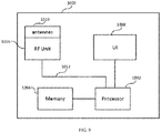
- Figure 9 illustrates a block diagram of an exemplary apparatus 1000 appropriate for implementing aspects of the disclosed embodiments.
- the apparatus 1000 is appropriate for use in a wireless network and can be implemented in one or more of the network node 110 or the user node 120.
- the apparatus 1000 includes or is coupled to a processor or computing hardware 1002, a memory 1004, a radio frequency (RF) unit 1006 and a user interface (UI) 1008.
- a processor or computing hardware 1002 a memory 1004
- RF radio frequency
- UI user interface
- the UI 1008 may be removed from the apparatus 1000.
- the apparatus 1000 may be administered remotely or locally through a wireless or wired network connection (not shown).
- the processor 1002 may be a single processing device or may comprise a plurality of processing devices including special purpose devices, such as for example, digital signal processing (DSP) devices, microprocessors, graphics processing units (GPU), specialized processing devices, or general purpose computer processing unit (CPU).
- DSP digital signal processing
- GPU graphics processing units
- CPU general purpose computer processing unit
- the processor 1002 often includes a CPU working in tandem with a DSP to handle signal processing tasks.
- the processor 1002 which can be implemented as one or more of the processors 112 and 124 described with respect to Figure 1 , may be configured to implement any one or more of the methods described herein.
- the processor 1002 is configured to be coupled to a memory 1004 which may be a combination of various types of volatile and non-volatile computer memory such as for example read only memory (ROM), random access memory (RAM), magnetic or optical disk, or other types of computer memory.
- the memory 1004 is configured to store computer program instructions that may be accessed and executed by the processor 1002 to cause the processor 1002 to perform a variety of desirable computer implemented processes or methods such as the methods as described herein.
- the program instructions stored in memory 1004 are organized as sets or groups of program instructions referred to in the industry with various terms such as programs, software components, software modules, units, etc. Each module may include a set of functionality designed to support a certain purpose. For example a software module may be of a recognized type such as a hypervisor, a virtual execution environment, an operating system, an application, a device driver, or other conventionally recognized type of software component. Also included in the memory 1004 are program data and data files which may be stored and processed by the processor 1002 while executing a set of computer program instructions.
- the apparatus 1000 can also include or be coupled to an RF Unit 1006 such as a transceiver, coupled to the processor 1002 that is configured to transmit and receive RF signals based on digital data 1012 exchanged with the processor 1002 and may be configured to transmit and receive radio signals with other nodes in a wireless network.
- the RF Unit 1006 includes receivers capable of receiving and interpreting messages sent from satellites in the global positioning system (GPS) and work together with information received from other transmitters to obtain positioning information pertaining to the location of the computing device 1000.
- GPS global positioning system
- the RF unit 1006 includes an antenna unit 1010 which in certain embodiments may include a plurality of antenna elements.
- the multiple antennas 1010 may be configured to support transmitting and receiving MIMO signals as may be used for beamforming.
- the antenna unit 1010 of Figure 6 can be implemented as one or more of the antenna unit 102 or the antenna unit 104 shown in Figure 1 .
- the UI 1008 may include one or more user interface elements such as a touch screen, keypad, buttons, voice command processor, as well as other elements adapted for exchanging information with a user.
- the UI 1008 may also include a display unit configured to display a variety of information appropriate for a computing device or mobile user equipment and may be implemented using any appropriate display type such as for example organic light emitting diodes (OLED), liquid crystal display (LCD), as well as less complex elements such as LEDs or indicator lamps.
- OLED organic light emitting diodes
- LCD liquid crystal display
- the aspects of the disclosed embodiments configure the beam parameters of the high frequency beams based on the accuracy of the user node localization with a low frequency link. This can improve the high frequency resource usage in the process.
- high frequency precoded/beamformed data transmission can be made more efficiently since the number of downlink high frequency beams that the user node needs to measure is smaller, thus reducing the user nodes power consumption and uplink signaling load.
- the accuracy of low frequency localization is determined by the network and the user node based on information including system frequency and d deployment density.
Landscapes
- Engineering & Computer Science (AREA)
- Computer Networks & Wireless Communication (AREA)
- Signal Processing (AREA)
- Physics & Mathematics (AREA)
- General Physics & Mathematics (AREA)
- Radar, Positioning & Navigation (AREA)
- Remote Sensing (AREA)
- Mobile Radio Communication Systems (AREA)
Claims (13)
- Nœud de réseau (110) destiné à un système de communication sans fil (100), le nœud de réseau (110) étant configuré pour :localiser un nœud d'utilisateur (120) dans une première opération de localisation à une première fréquence ;déterminer une valeur de précision associée à la première opération de localisation ;ajuster au moins un paramètre de faisceau destiné aux faisceaux radio à utiliser dans une seconde opération de localisation sur la base de la valeur de précision déterminée, la seconde opération de localisation étant mise en œuvre à une seconde fréquence qui est supérieure à la première fréquence ;dans lequel le nœud de réseau (110) est configuré pour déterminer la valeur de précision associée à la première opération de localisation par :le suivi d'un taux de changement d'un angle d'un signal de radiobalise transmis depuis le nœud d'utilisateur (120) par rapport au nœud de réseau (110) ; etsi le taux de changement de l'angle dépasse une valeur prédéfinie, l'attribution d'une première valeur à la valeur de précision, la première valeur étant inférieure à une valeur de précision précédente et si le taux de changement est inférieur à la valeur prédéfinie, l'attribution d'une seconde valeur à la valeur de précision, la seconde valeur étant supérieure à une valeur de précision précédente.
- Nœud de réseau (110) selon la revendication 1, dans lequel le nœud de réseau (110) est configuré en outre pour :recevoir une valeur de mesure de mouvement à partir du nœud d'utilisateur (120), la valeur de mesure de mouvement étant sur la base d'un ou de plusieurs changement(s) d'emplacement du nœud d'utilisateur (120) ou d'un changement d'orientation du nœud d'utilisateur (120) ;comparer la valeur de mesure de mouvement à une valeur de mesure de mouvement prédéfinie ; etajuster la valeur de précision déterminée sur la base de la comparaison.
- Nœud de réseau (110) selon l'une quelconque des revendications 1 ou 2, dans lequel le nœud de réseau (110) est configuré pour :ajuster l'au moins un paramètre de faisceau destiné aux faisceaux radio à utiliser dans la seconde localisation en ajustant un certain nombre de faisceaux radio et une largeur de faisceau des faisceaux radio à utiliser pour la seconde opération de localisation ; etenvoyer la configuration déterminée de faisceaux radio destinés à la seconde opération de localisation au nœud d'utilisateur (120).
- Nœud de réseau (110) selon l'une quelconque des revendications précédentes, dans lequel le nœud de réseau (110) est configuré pour localiser le nœud d'utilisateur (120) dans la seconde opération de localisation en diminuant le nombre de faisceaux radio destinés à la seconde opération de localisation à partir d'un nombre prédéfini de faisceaux radio lorsque la valeur de précision déterminée est supérieure à une valeur seuil de précision prédéfinie et en augmentant le nombre de faisceaux radio destinés à la seconde opération de localisation à partir du nombre prédéfini de faisceaux radio lorsque la valeur de précision déterminée est inférieure à la valeur seuil de précision prédéfinie.
- Nœud de réseau (110) selon l'une quelconque des revendications précédentes, dans lequel le nœud de réseau est configuré pour diminuer la largeur de faisceau des faisceaux radio à partir d'une largeur de faisceau prédéfinie lorsque la valeur de précision déterminée est supérieure à la valeur seuil de précision prédéfinie et augmenter la largeur de faisceau des faisceaux radio à partir de la largeur de faisceau prédéfinie lorsque la valeur de précision déterminée est inférieure à la valeur seuil de précision prédéfinie.
- Nœud de réseau (110) selon l'une quelconque des revendications précédentes, dans lequel le nœud de réseau (110) est configuré pour ajuster le nombre de faisceaux indépendamment de l'ajustement de la largeur de faisceau du motif de faisceau des faisceaux radio dans l'ensemble de faisceaux radio.
- Nœud de réseau (110) selon l'une quelconque des revendications précédentes, le nœud de réseau (110) est configuré pour suivre le taux de changement de l'angle du signal de radiobalise transmis depuis le nœud d'utilisateur (120) par rapport au nœud de réseau (110) par :la détermination d'un angle d'arrivée du signal de radiobalise ;la comparaison de l'angle déterminé à un angle d'arrivée préalablement déterminé ; etla détermination du taux de changement de l'angle du signal de radiobalise sur la base de la comparaison.
- Procédé comprenant :la localisation (S2.1) d'un nœud d'utilisateur dans une première opération de localisation mise en œuvre à une première fréquence ;la détermination (S2.4) d'une valeur de précision associée à la première opération de localisation ;l'ajustement (S2.6) d'au moins un paramètre de faisceau destiné aux faisceaux radio à utiliser dans une seconde opération de localisation sur la base de la valeur de précision déterminée, la seconde opération de localisation étant mise en œuvre à une seconde fréquence qui est supérieure à la première fréquence ;dans lequel le nœud de réseau (110) est configuré pour déterminer (S2.4) la valeur de précision associée à la première opération de localisation en :suivant (S3.1) un taux de changement d'un angle d'un signal de radiobalise transmis depuis le nœud d'utilisateur par rapport au nœud de réseau ; etsi le taux de changement de l'angle dépasse (S3.3) une valeur prédéfinie, en attribuant (S3.4) une première valeur à la valeur de précision, la première valeur étant inférieure à une valeur de précision précédente et si le taux de changement est inférieur à la valeur prédéfinie, en attribuant (S3.5) une seconde valeur à la valeur de précision, la seconde valeur étant supérieure à une valeur de précision précédente.
- Procédé selon la revendication 8, comprenant en outre :la réception (S4.2) d'une valeur de mesure de mouvement à partir du nœud d'utilisateur, la valeur de mesure de mouvement étant sur la base d'un ou de plusieurs changement(s) d'emplacement du nœud d'utilisateur ou d'un changement d'orientation du nœud d'utilisateur ;la comparaison (S5.2) de la valeur de mesure de mouvement à une valeur de mesure de mouvement prédéfinie ; etl'ajustement (S5.4) de la valeur de précision déterminée sur la base de la comparaison.
- Procédé selon l'une quelconque des revendications 8 ou 9, comprenant :l'ajustement (S2.6) de l'au moins un paramètre de faisceau destiné aux faisceaux radio à utiliser dans la seconde localisation en ajustant un certain nombre de faisceaux radio et une largeur de faisceau des faisceaux radio à utiliser pour la seconde opération de localisation ; etl'envoi (S2.8) de la configuration déterminée des faisceaux radio destinés à la seconde opération de localisation au nœud d'utilisateur.
- Procédé selon l'une quelconque des revendications 8 à 10, comprenant la diminution (S2.64) du nombre de faisceaux radio destiné à la seconde opération de localisation à partir d'un nombre prédéfini de faisceaux radio lorsqu'il est déterminé (S2.62) que la valeur de précision est supérieure à une valeur seuil de précision prédéfinie et augmentant (S2.65) le nombre de faisceaux radio destiné à la seconde opération de localisation à partir du nombre prédéfini de faisceaux radio lorsqu'il est déterminé (S2.62) que la valeur de précision est inférieure à la valeur seuil de précision prédéfinie.
- Procédé selon l'une quelconque des revendications 8 à 11, le procédé comprenant en outre la diminution (S2.64) de la largeur de faisceau des faisceaux radio à partir d'une largeur de faisceau prédéfinie lorsqu'il est déterminé (S2.62) que la valeur de précision est supérieure à la valeur seuil de précision prédéfinie et l'augmentation (S2.65) de la largeur de faisceau des faisceaux radioélectriques à partir de la largeur de faisceau prédéfinie lorsqu'il est déterminé (S2.62) que la valeur de précision est inférieure à la valeur seuil de précision prédéfinie.
- Procédé selon l'une quelconque des revendications 8 à 12, le procédé comprenant en outre le suivi (S3.1) du taux de changement de l'angle du signal de radiobalise transmis depuis le nœud d'utilisateur par rapport au nœud de réseau en déterminant (S3.11) un angle d'arrivée du signal de radiobalise, en comparant (S3.12) l'angle déterminé à un angle d'arrivée préalablement déterminé ; et
la détermination (S3.13) du taux de changement de l'angle du signal de radiobalise sur la base de la comparaison.
Applications Claiming Priority (1)
| Application Number | Priority Date | Filing Date | Title |
|---|---|---|---|
| PCT/EP2017/056552 WO2018171860A1 (fr) | 2017-03-20 | 2017-03-20 | Appareil pour configurer des faisceaux de signaux de référence sur la base d'une précision de localisation d'équipement utilisateur |
Publications (2)
| Publication Number | Publication Date |
|---|---|
| EP3586451A1 EP3586451A1 (fr) | 2020-01-01 |
| EP3586451B1 true EP3586451B1 (fr) | 2021-02-17 |
Family
ID=58410278
Family Applications (1)
| Application Number | Title | Priority Date | Filing Date |
|---|---|---|---|
| EP17713206.5A Active EP3586451B1 (fr) | 2017-03-20 | 2017-03-20 | Appareil pour configurer des faisceaux de signaux de référence sur la base d'une précision de localisation d'équipement utilisateur |
Country Status (4)
| Country | Link |
|---|---|
| US (1) | US11082104B2 (fr) |
| EP (1) | EP3586451B1 (fr) |
| CN (1) | CN110402548B (fr) |
| WO (1) | WO2018171860A1 (fr) |
Families Citing this family (15)
| Publication number | Priority date | Publication date | Assignee | Title |
|---|---|---|---|---|
| KR102439425B1 (ko) * | 2017-12-21 | 2022-09-05 | 삼성전자 주식회사 | 무선 셀룰라 통신 시스템에서 안테나 빔 추적 방법 및 장치 |
| CN111163480A (zh) * | 2018-11-07 | 2020-05-15 | 索尼公司 | 电子装置、无线通信方法和计算机可读介质 |
| US20200351814A1 (en) | 2019-05-02 | 2020-11-05 | Qualcomm Incorporated | Group delay timing accuracy for positioning in new radio |
| US11949472B2 (en) | 2019-06-05 | 2024-04-02 | Telefonaktiebolaget Lm Ericsson (Publ) | MU-MIMO operation control |
| US12113600B2 (en) | 2019-06-05 | 2024-10-08 | Telefonaktiebolaget Lm Ericsson (Publ) | Determination of candidate set of beams for beam tracking |
| WO2020244747A1 (fr) | 2019-06-05 | 2020-12-10 | Telefonaktiebolaget Lm Ericsson (Publ) | Commande de mesure de suivi de faisceau |
| US20220353842A1 (en) * | 2019-08-15 | 2022-11-03 | Sony Group Corporation | Methods and devices for on-demand positioning |
| CN110850365A (zh) * | 2019-10-28 | 2020-02-28 | 深圳市元征科技股份有限公司 | 一种定位方法、装置及终端设备 |
| WO2021081811A1 (fr) * | 2019-10-30 | 2021-05-06 | 华为技术有限公司 | Procédé de positionnement d'angle, appareil et dispositif |
| CN114631366B (zh) * | 2019-11-08 | 2025-08-26 | 索尼集团公司 | 处理无线设备的定位的方法以及相关网络节点和无线设备 |
| EP3910813B1 (fr) * | 2020-05-13 | 2025-10-08 | Nokia Technologies Oy | Appareil de sélection de faisceaux radio |
| CN115989691B (zh) | 2020-09-04 | 2024-05-14 | 高通股份有限公司 | 与aoa估计一起启用cli测量 |
| US11856568B2 (en) * | 2020-11-18 | 2023-12-26 | Qualcomm Incorporated | Assisted beam management between frequency bands |
| WO2022154642A1 (fr) * | 2021-01-18 | 2022-07-21 | 엘지전자 주식회사 | Procédé permettant de transmettre et de recevoir un signal dans un système de communication sans fil, et dispositif le prenant en charge |
| CN114650086B (zh) * | 2022-03-28 | 2023-04-18 | 东南大学 | 一种深度学习辅助的跨频段通信波束预测方法 |
Family Cites Families (13)
| Publication number | Priority date | Publication date | Assignee | Title |
|---|---|---|---|---|
| JPH05292010A (ja) * | 1992-04-10 | 1993-11-05 | Fujitsu Ltd | 無線チャネル割当て方法および装置 |
| GB2337171A (en) * | 1998-05-06 | 1999-11-10 | Motorola Ltd | Direction finder |
| JP4806307B2 (ja) * | 2006-07-28 | 2011-11-02 | 京セラ株式会社 | 無線通信方法、無線基地局、無線通信端末及び基地局制御装置 |
| KR100945880B1 (ko) * | 2007-09-28 | 2010-03-05 | 한국과학기술원 | 이동통신시스템에서의 빔분할다중접속시스템 및 방법 |
| CN101995574B (zh) * | 2010-11-03 | 2012-12-12 | 中国科学院声学研究所 | 一种近场聚焦波束形成定位法 |
| US9473229B2 (en) | 2012-10-05 | 2016-10-18 | Samsung Electronics Co., Ltd. | High-throughput beamforming MIMO receiver for millimeter wave communication and method |
| US9692459B2 (en) * | 2012-11-28 | 2017-06-27 | Intel Corporation | Using multiple frequency bands with beamforming assistance in a wireless network |
| JP2015185953A (ja) * | 2014-03-20 | 2015-10-22 | 株式会社Nttドコモ | ビーム選択方法、基地局、およびユーザ装置 |
| US9337969B2 (en) * | 2014-07-16 | 2016-05-10 | Qualcomm Incorporated | Low-frequency assisted methods for beamforming, timing and frequency offset in mm-wave access systems |
| CN104166134A (zh) * | 2014-08-25 | 2014-11-26 | 电子科技大学 | 一种实波束前视扫描雷达目标二维定位方法 |
| CN107852210B (zh) * | 2015-08-14 | 2020-08-07 | 华为技术有限公司 | 确定至少一个波束成形参数的接入节点、用户节点以及方法 |
| CN106778981B (zh) * | 2016-12-31 | 2019-10-18 | 山东大学 | 一种基于rfid的室内三维定位平台及其定位方法 |
| CN107064880A (zh) * | 2017-04-10 | 2017-08-18 | 南京航空航天大学 | 分布式多基雷达收发波束同步和波束控制的高精度方法 |
-
2017
- 2017-03-20 EP EP17713206.5A patent/EP3586451B1/fr active Active
- 2017-03-20 WO PCT/EP2017/056552 patent/WO2018171860A1/fr not_active Ceased
- 2017-03-20 CN CN201780088338.9A patent/CN110402548B/zh active Active
-
2019
- 2019-09-19 US US16/576,528 patent/US11082104B2/en active Active
Non-Patent Citations (1)
| Title |
|---|
| None * |
Also Published As
| Publication number | Publication date |
|---|---|
| US11082104B2 (en) | 2021-08-03 |
| CN110402548B (zh) | 2021-05-04 |
| EP3586451A1 (fr) | 2020-01-01 |
| CN110402548A (zh) | 2019-11-01 |
| US20200014445A1 (en) | 2020-01-09 |
| WO2018171860A1 (fr) | 2018-09-27 |
Similar Documents
| Publication | Publication Date | Title |
|---|---|---|
| US11082104B2 (en) | Apparatus for configuring reference signal beams based on accuracy of user equipment localization | |
| CN115812159B (zh) | 通过使用自适应相变设备来确定用户设备的位置 | |
| US11522590B2 (en) | Wireless communication apparatus and display method for use in wireless communication apparatus | |
| Nitsche et al. | Steering with eyes closed: mm-wave beam steering without in-band measurement | |
| US10405360B2 (en) | Method and equipment for establishing millimetre connection | |
| US20180227786A1 (en) | Mechanism for Beam Reciprocity Determination and Uplink Beam Management | |
| US12212392B2 (en) | Angle-of-arrival dependent re-configurable reflective devices | |
| US20170194706A1 (en) | Method and Apparatus for Directing an Antenna Beam based on Motion of a Communication Device | |
| JP2017041890A (ja) | モーション・センサを使用してモバイル無線デバイスのアンテナ・アレイを構成すること | |
| US10554277B2 (en) | Access node, user node and method for determining at least one beamforming parameter | |
| US11444677B2 (en) | Communication devices for efficient beam management | |
| US11349548B2 (en) | Method for detecting beam failure event by base station in wireless network | |
| US20180248610A1 (en) | Methods for radio communication and communication devices | |
| US20250055507A1 (en) | Multiple-Input, Multiple-Output Transmissions Using Adaptive Phase-Changing Devices | |
| EP3433943B1 (fr) | Noeud de communication sans fil conçu pour émettre des faisceaux d'antenne de différents types | |
| WO2022187801A1 (fr) | Apprentissage de vecteur de phase pour une communication activée par dispositif à changement de phase adaptatif | |
| EP4356533B1 (fr) | Formation de faisceau assistée par audio spatial pour communications en mode sécurisé | |
| WO2018137156A1 (fr) | Procédé et dispositif de commutation de faisceau analogique | |
| US12328605B2 (en) | Systems and methods for wireless channel information sharing | |
| EP4238242B1 (fr) | Contrôle de transmissions radio, basé sur la communication lumineuse | |
| US20250062815A1 (en) | Ue-side beam selection procedure |
Legal Events
| Date | Code | Title | Description |
|---|---|---|---|
| STAA | Information on the status of an ep patent application or granted ep patent |
Free format text: STATUS: UNKNOWN |
|
| STAA | Information on the status of an ep patent application or granted ep patent |
Free format text: STATUS: THE INTERNATIONAL PUBLICATION HAS BEEN MADE |
|
| PUAI | Public reference made under article 153(3) epc to a published international application that has entered the european phase |
Free format text: ORIGINAL CODE: 0009012 |
|
| STAA | Information on the status of an ep patent application or granted ep patent |
Free format text: STATUS: REQUEST FOR EXAMINATION WAS MADE |
|
| 17P | Request for examination filed |
Effective date: 20190926 |
|
| AK | Designated contracting states |
Kind code of ref document: A1 Designated state(s): AL AT BE BG CH CY CZ DE DK EE ES FI FR GB GR HR HU IE IS IT LI LT LU LV MC MK MT NL NO PL PT RO RS SE SI SK SM TR |
|
| AX | Request for extension of the european patent |
Extension state: BA ME |
|
| DAV | Request for validation of the european patent (deleted) | ||
| DAX | Request for extension of the european patent (deleted) | ||
| GRAP | Despatch of communication of intention to grant a patent |
Free format text: ORIGINAL CODE: EPIDOSNIGR1 |
|
| STAA | Information on the status of an ep patent application or granted ep patent |
Free format text: STATUS: GRANT OF PATENT IS INTENDED |
|
| INTG | Intention to grant announced |
Effective date: 20200821 |
|
| GRAS | Grant fee paid |
Free format text: ORIGINAL CODE: EPIDOSNIGR3 |
|
| GRAA | (expected) grant |
Free format text: ORIGINAL CODE: 0009210 |
|
| STAA | Information on the status of an ep patent application or granted ep patent |
Free format text: STATUS: THE PATENT HAS BEEN GRANTED |
|
| AK | Designated contracting states |
Kind code of ref document: B1 Designated state(s): AL AT BE BG CH CY CZ DE DK EE ES FI FR GB GR HR HU IE IS IT LI LT LU LV MC MK MT NL NO PL PT RO RS SE SI SK SM TR |
|
| REG | Reference to a national code |
Ref country code: GB Ref legal event code: FG4D |
|
| REG | Reference to a national code |
Ref country code: CH Ref legal event code: EP |
|
| REG | Reference to a national code |
Ref country code: DE Ref legal event code: R096 Ref document number: 602017032630 Country of ref document: DE |
|
| REG | Reference to a national code |
Ref country code: AT Ref legal event code: REF Ref document number: 1362861 Country of ref document: AT Kind code of ref document: T Effective date: 20210315 |
|
| REG | Reference to a national code |
Ref country code: IE Ref legal event code: FG4D |
|
| REG | Reference to a national code |
Ref country code: LT Ref legal event code: MG9D |
|
| REG | Reference to a national code |
Ref country code: NL Ref legal event code: MP Effective date: 20210217 |
|
| PG25 | Lapsed in a contracting state [announced via postgrant information from national office to epo] |
Ref country code: FI Free format text: LAPSE BECAUSE OF FAILURE TO SUBMIT A TRANSLATION OF THE DESCRIPTION OR TO PAY THE FEE WITHIN THE PRESCRIBED TIME-LIMIT Effective date: 20210217 Ref country code: GR Free format text: LAPSE BECAUSE OF FAILURE TO SUBMIT A TRANSLATION OF THE DESCRIPTION OR TO PAY THE FEE WITHIN THE PRESCRIBED TIME-LIMIT Effective date: 20210518 Ref country code: HR Free format text: LAPSE BECAUSE OF FAILURE TO SUBMIT A TRANSLATION OF THE DESCRIPTION OR TO PAY THE FEE WITHIN THE PRESCRIBED TIME-LIMIT Effective date: 20210217 Ref country code: PT Free format text: LAPSE BECAUSE OF FAILURE TO SUBMIT A TRANSLATION OF THE DESCRIPTION OR TO PAY THE FEE WITHIN THE PRESCRIBED TIME-LIMIT Effective date: 20210617 Ref country code: NO Free format text: LAPSE BECAUSE OF FAILURE TO SUBMIT A TRANSLATION OF THE DESCRIPTION OR TO PAY THE FEE WITHIN THE PRESCRIBED TIME-LIMIT Effective date: 20210517 Ref country code: BG Free format text: LAPSE BECAUSE OF FAILURE TO SUBMIT A TRANSLATION OF THE DESCRIPTION OR TO PAY THE FEE WITHIN THE PRESCRIBED TIME-LIMIT Effective date: 20210517 Ref country code: LT Free format text: LAPSE BECAUSE OF FAILURE TO SUBMIT A TRANSLATION OF THE DESCRIPTION OR TO PAY THE FEE WITHIN THE PRESCRIBED TIME-LIMIT Effective date: 20210217 |
|
| REG | Reference to a national code |
Ref country code: AT Ref legal event code: MK05 Ref document number: 1362861 Country of ref document: AT Kind code of ref document: T Effective date: 20210217 |
|
| PG25 | Lapsed in a contracting state [announced via postgrant information from national office to epo] |
Ref country code: NL Free format text: LAPSE BECAUSE OF FAILURE TO SUBMIT A TRANSLATION OF THE DESCRIPTION OR TO PAY THE FEE WITHIN THE PRESCRIBED TIME-LIMIT Effective date: 20210217 Ref country code: LV Free format text: LAPSE BECAUSE OF FAILURE TO SUBMIT A TRANSLATION OF THE DESCRIPTION OR TO PAY THE FEE WITHIN THE PRESCRIBED TIME-LIMIT Effective date: 20210217 Ref country code: PL Free format text: LAPSE BECAUSE OF FAILURE TO SUBMIT A TRANSLATION OF THE DESCRIPTION OR TO PAY THE FEE WITHIN THE PRESCRIBED TIME-LIMIT Effective date: 20210217 Ref country code: RS Free format text: LAPSE BECAUSE OF FAILURE TO SUBMIT A TRANSLATION OF THE DESCRIPTION OR TO PAY THE FEE WITHIN THE PRESCRIBED TIME-LIMIT Effective date: 20210217 Ref country code: SE Free format text: LAPSE BECAUSE OF FAILURE TO SUBMIT A TRANSLATION OF THE DESCRIPTION OR TO PAY THE FEE WITHIN THE PRESCRIBED TIME-LIMIT Effective date: 20210217 |
|
| PG25 | Lapsed in a contracting state [announced via postgrant information from national office to epo] |
Ref country code: IS Free format text: LAPSE BECAUSE OF FAILURE TO SUBMIT A TRANSLATION OF THE DESCRIPTION OR TO PAY THE FEE WITHIN THE PRESCRIBED TIME-LIMIT Effective date: 20210617 |
|
| PG25 | Lapsed in a contracting state [announced via postgrant information from national office to epo] |
Ref country code: SM Free format text: LAPSE BECAUSE OF FAILURE TO SUBMIT A TRANSLATION OF THE DESCRIPTION OR TO PAY THE FEE WITHIN THE PRESCRIBED TIME-LIMIT Effective date: 20210217 Ref country code: AT Free format text: LAPSE BECAUSE OF FAILURE TO SUBMIT A TRANSLATION OF THE DESCRIPTION OR TO PAY THE FEE WITHIN THE PRESCRIBED TIME-LIMIT Effective date: 20210217 Ref country code: EE Free format text: LAPSE BECAUSE OF FAILURE TO SUBMIT A TRANSLATION OF THE DESCRIPTION OR TO PAY THE FEE WITHIN THE PRESCRIBED TIME-LIMIT Effective date: 20210217 Ref country code: CZ Free format text: LAPSE BECAUSE OF FAILURE TO SUBMIT A TRANSLATION OF THE DESCRIPTION OR TO PAY THE FEE WITHIN THE PRESCRIBED TIME-LIMIT Effective date: 20210217 |
|
| REG | Reference to a national code |
Ref country code: CH Ref legal event code: PL |
|
| REG | Reference to a national code |
Ref country code: DE Ref legal event code: R097 Ref document number: 602017032630 Country of ref document: DE |
|
| PG25 | Lapsed in a contracting state [announced via postgrant information from national office to epo] |
Ref country code: MC Free format text: LAPSE BECAUSE OF FAILURE TO SUBMIT A TRANSLATION OF THE DESCRIPTION OR TO PAY THE FEE WITHIN THE PRESCRIBED TIME-LIMIT Effective date: 20210217 Ref country code: RO Free format text: LAPSE BECAUSE OF FAILURE TO SUBMIT A TRANSLATION OF THE DESCRIPTION OR TO PAY THE FEE WITHIN THE PRESCRIBED TIME-LIMIT Effective date: 20210217 Ref country code: DK Free format text: LAPSE BECAUSE OF FAILURE TO SUBMIT A TRANSLATION OF THE DESCRIPTION OR TO PAY THE FEE WITHIN THE PRESCRIBED TIME-LIMIT Effective date: 20210217 Ref country code: SK Free format text: LAPSE BECAUSE OF FAILURE TO SUBMIT A TRANSLATION OF THE DESCRIPTION OR TO PAY THE FEE WITHIN THE PRESCRIBED TIME-LIMIT Effective date: 20210217 |
|
| REG | Reference to a national code |
Ref country code: BE Ref legal event code: MM Effective date: 20210331 |
|
| PLBE | No opposition filed within time limit |
Free format text: ORIGINAL CODE: 0009261 |
|
| STAA | Information on the status of an ep patent application or granted ep patent |
Free format text: STATUS: NO OPPOSITION FILED WITHIN TIME LIMIT |
|
| 26N | No opposition filed |
Effective date: 20211118 |
|
| PG25 | Lapsed in a contracting state [announced via postgrant information from national office to epo] |
Ref country code: ES Free format text: LAPSE BECAUSE OF FAILURE TO SUBMIT A TRANSLATION OF THE DESCRIPTION OR TO PAY THE FEE WITHIN THE PRESCRIBED TIME-LIMIT Effective date: 20210217 Ref country code: AL Free format text: LAPSE BECAUSE OF FAILURE TO SUBMIT A TRANSLATION OF THE DESCRIPTION OR TO PAY THE FEE WITHIN THE PRESCRIBED TIME-LIMIT Effective date: 20210217 Ref country code: CH Free format text: LAPSE BECAUSE OF NON-PAYMENT OF DUE FEES Effective date: 20210331 Ref country code: LI Free format text: LAPSE BECAUSE OF NON-PAYMENT OF DUE FEES Effective date: 20210331 Ref country code: LU Free format text: LAPSE BECAUSE OF NON-PAYMENT OF DUE FEES Effective date: 20210320 Ref country code: IE Free format text: LAPSE BECAUSE OF NON-PAYMENT OF DUE FEES Effective date: 20210320 |
|
| PG25 | Lapsed in a contracting state [announced via postgrant information from national office to epo] |
Ref country code: SI Free format text: LAPSE BECAUSE OF FAILURE TO SUBMIT A TRANSLATION OF THE DESCRIPTION OR TO PAY THE FEE WITHIN THE PRESCRIBED TIME-LIMIT Effective date: 20210217 |
|
| PG25 | Lapsed in a contracting state [announced via postgrant information from national office to epo] |
Ref country code: IT Free format text: LAPSE BECAUSE OF FAILURE TO SUBMIT A TRANSLATION OF THE DESCRIPTION OR TO PAY THE FEE WITHIN THE PRESCRIBED TIME-LIMIT Effective date: 20210217 |
|
| PG25 | Lapsed in a contracting state [announced via postgrant information from national office to epo] |
Ref country code: IS Free format text: LAPSE BECAUSE OF FAILURE TO SUBMIT A TRANSLATION OF THE DESCRIPTION OR TO PAY THE FEE WITHIN THE PRESCRIBED TIME-LIMIT Effective date: 20210617 Ref country code: FR Free format text: LAPSE BECAUSE OF NON-PAYMENT OF DUE FEES Effective date: 20210417 |
|
| PG25 | Lapsed in a contracting state [announced via postgrant information from national office to epo] |
Ref country code: BE Free format text: LAPSE BECAUSE OF NON-PAYMENT OF DUE FEES Effective date: 20210331 |
|
| PG25 | Lapsed in a contracting state [announced via postgrant information from national office to epo] |
Ref country code: CY Free format text: LAPSE BECAUSE OF FAILURE TO SUBMIT A TRANSLATION OF THE DESCRIPTION OR TO PAY THE FEE WITHIN THE PRESCRIBED TIME-LIMIT Effective date: 20210217 |
|
| PG25 | Lapsed in a contracting state [announced via postgrant information from national office to epo] |
Ref country code: HU Free format text: LAPSE BECAUSE OF FAILURE TO SUBMIT A TRANSLATION OF THE DESCRIPTION OR TO PAY THE FEE WITHIN THE PRESCRIBED TIME-LIMIT; INVALID AB INITIO Effective date: 20170320 |
|
| PG25 | Lapsed in a contracting state [announced via postgrant information from national office to epo] |
Ref country code: MK Free format text: LAPSE BECAUSE OF FAILURE TO SUBMIT A TRANSLATION OF THE DESCRIPTION OR TO PAY THE FEE WITHIN THE PRESCRIBED TIME-LIMIT Effective date: 20210217 |
|
| PG25 | Lapsed in a contracting state [announced via postgrant information from national office to epo] |
Ref country code: TR Free format text: LAPSE BECAUSE OF FAILURE TO SUBMIT A TRANSLATION OF THE DESCRIPTION OR TO PAY THE FEE WITHIN THE PRESCRIBED TIME-LIMIT Effective date: 20210217 |
|
| PG25 | Lapsed in a contracting state [announced via postgrant information from national office to epo] |
Ref country code: MT Free format text: LAPSE BECAUSE OF FAILURE TO SUBMIT A TRANSLATION OF THE DESCRIPTION OR TO PAY THE FEE WITHIN THE PRESCRIBED TIME-LIMIT Effective date: 20210217 |
|
| PGFP | Annual fee paid to national office [announced via postgrant information from national office to epo] |
Ref country code: GB Payment date: 20260202 Year of fee payment: 10 |
|
| PGFP | Annual fee paid to national office [announced via postgrant information from national office to epo] |
Ref country code: DE Payment date: 20260204 Year of fee payment: 10 |