EP3586910B1 - Réseaux d'électrodes pour une prothèse visuelle - Google Patents
Réseaux d'électrodes pour une prothèse visuelle Download PDFInfo
- Publication number
- EP3586910B1 EP3586910B1 EP19191113.0A EP19191113A EP3586910B1 EP 3586910 B1 EP3586910 B1 EP 3586910B1 EP 19191113 A EP19191113 A EP 19191113A EP 3586910 B1 EP3586910 B1 EP 3586910B1
- Authority
- EP
- European Patent Office
- Prior art keywords
- electrode array
- electrodes
- array
- flexible circuit
- retina
- Prior art date
- Legal status (The legal status is an assumption and is not a legal conclusion. Google has not performed a legal analysis and makes no representation as to the accuracy of the status listed.)
- Active
Links
Images






Classifications
-
- A—HUMAN NECESSITIES
- A61—MEDICAL OR VETERINARY SCIENCE; HYGIENE
- A61N—ELECTROTHERAPY; MAGNETOTHERAPY; RADIATION THERAPY; ULTRASOUND THERAPY
- A61N1/00—Electrotherapy; Circuits therefor
- A61N1/02—Details
- A61N1/04—Electrodes
- A61N1/05—Electrodes for implantation or insertion into the body, e.g. heart electrode
- A61N1/0526—Head electrodes
- A61N1/0543—Retinal electrodes
-
- A—HUMAN NECESSITIES
- A61—MEDICAL OR VETERINARY SCIENCE; HYGIENE
- A61N—ELECTROTHERAPY; MAGNETOTHERAPY; RADIATION THERAPY; ULTRASOUND THERAPY
- A61N1/00—Electrotherapy; Circuits therefor
- A61N1/18—Applying electric currents by contact electrodes
- A61N1/32—Applying electric currents by contact electrodes alternating or intermittent currents
- A61N1/36—Applying electric currents by contact electrodes alternating or intermittent currents for stimulation
- A61N1/36046—Applying electric currents by contact electrodes alternating or intermittent currents for stimulation of the eye
Definitions
- the present disclosure relates to neural implants, particularly visual prostheses. More particularly, it relates to electrode arrays and their leads for use in visual prostheses for stimulating a retina.
- Electrode arrays for biological implants are disclosed, particularly for stimulating a retina.
- the present disclosure provides array designs for improving apposition (reducing the space between the electrodes and the retina).
- the present disclosure also provides electrode array designs that can be made approximately spherical to increase the field of view of a visual prosthesis while still maintaining good apposition.
- An aspect of the invention is the subject matter recited in claim 1.
- US2008/0288037 A1 , WO2009/003182 A1 , and WO 2008/101225 A2 disclose flexible circuit electrode arrays.
- US 8145322 B1 discloses a flexible circuit electrode array device and a method for backside processing of a flexible circuit electrode device.
- EP 1790 380A1 discloses a microelectrode array and method for producing the same.
- US 2004/0238819 A1 discloses serpentine and corduroy circuits to enhance the stretchability of a stretchable electronic device.
- US 2004/0147992 A1 discloses an implantable medical assembly.
- FIG. 10 illustrates an aspect of the invention according to claim 1, whereas the other figures illustrates one or more alternative examples.
- Biological implants such as ocular implants to be attached to the human retina or other neural interface devices, often comprise a set of electronic components which may control and monitor the function of the implant, and the neural interfacing component itself, usually an array of electrodes. While described here in terms of an electrode array to be attached to the retina for a visual prosthesis, the present disclosure may also be applicable for an electrode array to attached to the visual cortex for a visual prosthesis, a spinal cord stimulator, a deep brain stimulator, a cortical or peripheral nerve interface (stimulator or recorder) for a motor prosthesis, or a wide range of other neural interface devices. Electrode arrays benefit from both being flexible to conform to the target tissue, and from being pre-formed to approximate that target tissue.
- FIG. 1A shows a perspective view of the implanted portion of a visual prosthesis.
- a flexible circuit includes a flexible circuit electrode array 10 which is mounted by a retinal tack (not shown) through tack opening 29, or similar means to the epiretinal surface.
- the flexible circuit electrode array 10 is electrically coupled by a flexible circuit cable 12, which pierces the sclera and is electrically coupled to an electronics package 14, external to the sclera.
- the electronics package 14 is electrically coupled to a secondary inductive coil 16.
- the secondary inductive coil 16 is made from wound wire.
- the secondary inductive coil 16 may be made from a flexible circuit polymer sandwich with wire traces deposited between layers of flexible circuit polymer.
- the secondary inductive coil receives power and data from a primary inductive coil 17, which is external to the body.
- the electronics package 14 and secondary inductive coil 16 are held together by the molded body 18.
- the molded body 18 holds the secondary inductive coil 16 and electronics package 14 in an end to end orientation and minimizes the thickness or height above the sclera of the entire device.
- the molded body 18 may also include suture tabs 20.
- the molded body 18 narrows to form a strap 22 which surrounds the sclera and holds the molded body 18, secondary inductive coil 16, and electronics package 14 in place.
- the molded body 18, suture tabs 20 and strap 22 are preferably an integrated unit made of silicone elastomer. Silicone elastomer can be formed in a pre-curved shape to match the curvature of a typical sclera. However, silicone remains flexible enough to accommodate implantation and to adapt to variations in the curvature of an individual sclera.
- the secondary inductive coil 16 and molded body 18 are preferably oval shaped.
- a strap 22 can better support an oval shaped coil. It should be noted that the entire implant is attached to and supported by the sclera. An eye moves constantly.
- the eye moves to scan a scene and also has a jitter motion to improve acuity. Even though such motion is useless in the blind, it often continues long after a person has lost their sight.
- eye motion does not cause any flexing which might fatigue, and eventually damage, the device.
- a video camera 32 on the glasses 35, captures a video image that is sent to a video processing unit (VPU) 30.
- the VPU 30 processes the image from the camera 32 and transforms it into electrical stimulation patterns that are transmitted to the external coil 17.
- the external coil 17 sends the electrical stimulation patterns and power via radio-frequency (RF) telemetry to the implanted retinal stimulation system.
- the internal coil 16 of the retinal stimulation system receives the RF commands from the external coil 17 and transmits them to the electronics package 14 that in turn delivers stimulation to the retina via the electrode array 10.
- the retinal stimulation system may communicate safety and operational status back to the VPU 30 by transmitting RF telemetry from the internal coil 16 to the external coil 17. Separate coils for transmitting and receiving may also be used.
- the visual prosthesis apparatus may be configured to electrically activate the retinal stimulation system only when it is powered by the VPU 30 through the external coil 17.
- the flexible circuit 1 is preferably a sandwiched polymer body with the electrode array 10 at one end bond pads 13 for connecting the array to the electronics package 14 at the other end, and traces through a cable 12 connecting bond pads to electrodes.
- Polymer materials are useful as electrode array bodies for neural stimulation. They are particularly useful for retinal stimulation to create artificial vision, cochlear stimulation to create artificial hearing, or cortical stimulation for many purposes. Regardless of which polymer is used, the basic construction method is the same.
- a layer of polymer is laid down, commonly by some form of chemical vapor deposition, spinning, meniscus coating or casting.
- a layer of metal, preferably platinum, is applied to the polymer and patterned to create electrodes bond pads and leads connecting electrodes to bond pads.
- Patterning is commonly done by photolithographic methods.
- a second layer of polymer is applied over the metal layer and patterned to leave openings for the electrodes, or openings are created later by means such as laser ablation.
- the array 10 its supply cable 12 and bond pads 13 are formed of a single body.
- multiple alternating layers of metal and polymer may be applied to obtain more metal traces within a given width.
- the pressure applied against the retina, or other neural tissue, by an electrode array is critical. Too little pressure causes increased electrical resistance between the array and retina, along with electric field dispersion. Too much pressure may block blood flow causing retinal ischemia and hemorrhage. Pressure on the neural retina may also block axonal flow or cause neuronal atrophy leading to optic atrophy.
- Common flexible circuit fabrication techniques such as photolithography generally require that a flexible circuit electrode array be made flat. Since the retina is approximately spherical, a flat array will necessarily apply more pressure near its edges, than at its center. Further, the edges of a flexible circuit polymer array may be quite sharp and cut the delicate retinal tissue. With most polymers, it is possible to curve them when heated in a mold.
- thermoplastic polymer such as liquid crystal polymer
- PDMS Polydimethylsiloxane
- the electrode array 10 comprises a number of electrical traces which may follow different pattern designs.
- the electrical traces run on multiple layers on top of one another.
- a layer of electrical traces may follow a certain arrangement, and a second layer of electrical traces have its own arrangement, with the two layers being separated by a thin layer of dielectric material so as to achieve electrical insulation.
- an array may contain 60 thin platinum traces that connect the electrodes to the bond pads.
- half (i.e., 30) of the traces are on one layer of polyimide 405 and the other half on a second layer of polyimide 410.
- Each trace in FIGS. 4A and 4B connects to one circular electrode 415.
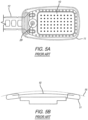
- FIGs 5A and 5B represent the existing state of the art.
- a polyimide flexible circuit includes an electrode array 10 and connected cable 12.
- the electrode array 10 portion of the polyimide flexible circuit is encased in a PDMS coating 11.
- the PDMS coating 11 protects the retina 15 from the sharp edges of the polyimide.
- the PDMS coating 11 creates a gap between the electrodes in the electrode array 10 and the retina 15.
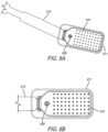
- FIGs 6A through 6D show an improved electrode array with curved edges.
- This design decreases the overall size of the electrode array without decreasing the size of the electrode field.
- This design uses a flexible circuit as shown in FIG. 3 , including an electrode array 610 and cable 612.
- the flexible circuit electrode array 610 is curved up at is edges through thermoforming and over molded in that position by the PDMS coating 611.
- the array is tacked to the retina with a tack (not shown) through the tack opening 629.
- curving the flexible circuit electrode array 610 up at its edges both decreases the overall size and allows the flexible circuit electrode array 610 to lay flat against the retina 15.
- the figures are not drawn to scale. This figure, along with FIG.
- the flexible circuit is polyimide about 12 ⁇ m thick.
- the polymer over-mold is silicone about 40 ⁇ m thick.
- FIG. 6D shows more detail.
- the flexible circuit includes perforated tabs 615 along is edges. Curving the flexible circuit electrode array in a solid wall would significantly reduce flexibility.
- the tabs 615 allow the flexible circuit electrode array to be curved up while remaining flexible.
- the perforated tabs 615 are embedded in the soft polymer 611 after they are curved. This both makes the flexible circuit easier to curve and improves adhesion between the flexible circuit and the soft polymer 611 by the soft polymer 611 binding to itself through holes in the perforated tabs 615.
- the curve up at the edges of the array 610 preferably has a radius between 0.05mm to 0.10mm. Too much curvature may result in sharp edges contacting the retina 15. Too little curvature may result in the tabs 615 not lifting off the surface of a small retina 15. It is important that the top of the tabs not touch the retina 15, as they may have sharp edges.
- the radius is preferably slightly below bottom of the tabs 615. If the bottom of the tabs 615 is at the radius the spaces between tabs 615 could produce sharp edges against the retina 15. If the bottom of the tabs 615 is too far above the radius, the resulting wall will reduce flexibility.
- FIG. 7A and 7B show an example that is not an embodiment for a wider field of view.
- the metal bond pads, traces and electrodes are patterned by photolithography, a flat process.
- the thin film of the flexible circuit preferably polyimide, cannot stretch without breaking the electrical traces.
- the flexible circuit is formed in wings 714 allowing for radial slots or spaces between the wings. Preferably the slots are in a wedge shape.
- the flexible circuit cable 712 exits from one wing 714. Closing the gaps between the wings 714 allows the array 710 to be curved through thermoforming into an approximately a spherical shape.
- the array is still coated with a softer polymer 711, preferably PDMS.
- the soft polymer coating 711 can hold the wings 714 together or the wings 714 can remain separate and curve when tacked to a retina through tack opening 729.
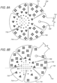
- FIG. 8A and 8B show the electrode array of FIG. 7 in greater detail, including aggregate electrodes. Neurons in the periphery of the retina produce lower resolution vision and generally require more charge to create a percept (have a higher threshold). Like FIG. 7 , FIG 8A shows an array 710 with wings 714. The electrodes in the periphery are aggregate in one pixel maps to either four electrodes 716 or three electrode 718. One of skill in the art will understand that other numbers of grouped electrodes fall within the spirit of the invention.
- FIG 8A shows an array with a circular and symmetrical layout.
- FIG. 8B shows the array of FIG. 8A , but with asymmetrical layout. Line 719 in FIG 8B shows the centerline of vision as the array should be implanted.
- FIGs. 8A through 8C additionally provide variable pitch electrodes across the array surface. Natural vision is higher resolution at the macula, center, and lower resolution in the periphery. Variable pitch electrode arrays provide more natural vision.
- FIG. 8C shows another alternate example that is not an embodiment.
- the electrode array 810 is shaped like fork with lateral wings 814 and lateral slots in a common direction, rather than radial wings as shown in FIGS. 8A and 8B .
- One disadvantage of radial wings is the limit of the depth of the slots between wings.
- the central portion of the array must be large enough to carry all of the traces linking the electrodes to bond pads.
- the design of FIG. 8C allows for deeper slots between the wings 814 as the traces run laterally through an end portion.
- the design provides improved apposition and fit to the retina. This arrangement is more conducive to a linear array arraignment, which simplifies electrode mapping.
- the fork design is also easier to fold to fit through a small sclerotomy (incision in the sclera).
- FIG. 9A and 9B is similar to the example that is not an embodiment of FIG. 7 , but provides more electrodes for higher resolution vision. Even though it is higher resolution over all, it is still advantageous to include a variable pitch with higher resolution 722 near the fovea, and lower resolution 721 in the periphery.
- FIG. 10 illustrates an aspect of the invention according to claim 1.
- FIG. 10 shows an alternate flexible circuit cable 1012.
- the flexible circuit cable 1012 may be used in conjunction with any of the previously described array designs 1010, but the array cable 1012 undulates to provide a stress relief feature 1015. Note than most of this disclosure is directed to the difficulty of curving a flexible circuit in a spherical shape. The undulations are cylindrical in shape and thus easier to achieve.
- the stress relieve feature 1015 reduces the transmission of stress from the electronics package or sclerotomy to the electrode array 1010.
- a smaller electrode array is optimized for Age Related Macular Degeneration (AMD).
- AMD Age Related Macular Degeneration
- AMD the retina looses light sensation in the center or macula and the disease progresses outward.
- Patients suffering from AMD often have good peripheral vision long after the vision in the macula is completely lost.
- Retinitis Pigmentosa (RP) operates in almost the opposite as AMD. Vision is first lost in the periphery and the disease progresses inward. However, RP patients see less of a difference between central and peripheral vision.
Landscapes
- Health & Medical Sciences (AREA)
- Ophthalmology & Optometry (AREA)
- Engineering & Computer Science (AREA)
- Biomedical Technology (AREA)
- Nuclear Medicine, Radiotherapy & Molecular Imaging (AREA)
- Radiology & Medical Imaging (AREA)
- Life Sciences & Earth Sciences (AREA)
- Animal Behavior & Ethology (AREA)
- General Health & Medical Sciences (AREA)
- Public Health (AREA)
- Veterinary Medicine (AREA)
- Cardiology (AREA)
- Heart & Thoracic Surgery (AREA)
- Prostheses (AREA)
- Electrotherapy Devices (AREA)
Claims (3)
- Dispositif implantable pour une prothèse visuelle, le dispositif implantable étant destiné à stimuler un tissu neuronal, comprenant :un circuit flexible comprenant un corps polymère enserré présentant : à une première extrémité, un réseau d'électrodes comprenant une pluralité d'électrodes ; à une seconde extrémité, des plots de connexion destinés à connecter le réseau à un boîtier électronique ; et des traces à travers un câble connectant les plots de connexion aux électrodes, le corps polymère enserré comprenant :une couche de base de polyimide ;une couche métallique sur la couche de base de polyimide formant les électrodes dans le réseau d'électrodes au niveau de la première extrémité, les plots de connexion dans une région de plots de connexion au niveau de la seconde extrémité opposée à la première extrémité et les traces connectant les électrodes aux plots de connexion à travers le câble entre le réseau d'électrodes et la région de plots de connexion ;une couche supérieure de polyimide sur la couche de base de polyimide et une couche métallique, et définissant des ouvertures pour les électrodes ;dans lequel :le réseau d'électrodes est revêtu d'une couche de PDMS qui est ouverte pour exposer les électrodes ;le réseau d'électrodes est flexible pour se conformer au tissu neuronal, et préformé pour se rapprocher du tissu neuronal ; etcaractérisé en ce que :
le câble comprend une pluralité d'ondulations pour fournir des caractéristiques de soulagement de contrainte configurées pour réduire une transmission de contrainte à travers le câble. - Dispositif implantable selon la revendication 1, dans lequel la pluralité d'ondulations sont de forme cylindrique.
- Dispositif implantable selon la revendication 1 ou la revendication 2, dans lequel la caractéristique de soulagement de contrainte (1015) est configurée pour réduire une contrainte entre le boîtier électronique et le réseau d'électrodes (1010), lorsque le boîtier électronique (14) est connecté aux plots de connexion.
Applications Claiming Priority (3)
| Application Number | Priority Date | Filing Date | Title |
|---|---|---|---|
| US201562266513P | 2015-12-11 | 2015-12-11 | |
| EP16822845.0A EP3386584B1 (fr) | 2015-12-11 | 2016-12-09 | Réseaux d'électrodes pour prothèse visuelle |
| PCT/US2016/066017 WO2017100708A1 (fr) | 2015-12-11 | 2016-12-09 | Réseaux d'électrodes pour prothèse visuelle |
Related Parent Applications (2)
| Application Number | Title | Priority Date | Filing Date |
|---|---|---|---|
| EP16822845.0A Division EP3386584B1 (fr) | 2015-12-11 | 2016-12-09 | Réseaux d'électrodes pour prothèse visuelle |
| EP16822845.0A Division-Into EP3386584B1 (fr) | 2015-12-11 | 2016-12-09 | Réseaux d'électrodes pour prothèse visuelle |
Publications (3)
| Publication Number | Publication Date |
|---|---|
| EP3586910A1 EP3586910A1 (fr) | 2020-01-01 |
| EP3586910B1 true EP3586910B1 (fr) | 2023-08-09 |
| EP3586910C0 EP3586910C0 (fr) | 2023-08-09 |
Family
ID=57750618
Family Applications (2)
| Application Number | Title | Priority Date | Filing Date |
|---|---|---|---|
| EP19191113.0A Active EP3586910B1 (fr) | 2015-12-11 | 2016-12-09 | Réseaux d'électrodes pour une prothèse visuelle |
| EP16822845.0A Active EP3386584B1 (fr) | 2015-12-11 | 2016-12-09 | Réseaux d'électrodes pour prothèse visuelle |
Family Applications After (1)
| Application Number | Title | Priority Date | Filing Date |
|---|---|---|---|
| EP16822845.0A Active EP3386584B1 (fr) | 2015-12-11 | 2016-12-09 | Réseaux d'électrodes pour prothèse visuelle |
Country Status (3)
| Country | Link |
|---|---|
| US (2) | US10493267B2 (fr) |
| EP (2) | EP3586910B1 (fr) |
| WO (1) | WO2017100708A1 (fr) |
Families Citing this family (6)
| Publication number | Priority date | Publication date | Assignee | Title |
|---|---|---|---|---|
| US11439832B2 (en) | 2019-01-09 | 2022-09-13 | Stimwave Technologies Incorporated | Implantable electronic devices |
| WO2020176948A1 (fr) * | 2019-03-06 | 2020-09-10 | The Bionics Institute Of Australia | Appareils et procédés électriques pour œil |
| US12017082B2 (en) | 2019-11-13 | 2024-06-25 | Curonix Llc | Manufacturing implantable tissue stimulators |
| KR102408304B1 (ko) * | 2020-01-23 | 2022-06-14 | 재단법인대구경북과학기술원 | 변형 가능한 망막 전극 장치 |
| US11856708B2 (en) * | 2021-03-22 | 2023-12-26 | Carnegie Mellon University | Stretchable 3D-printed circuit boards |
| CN115054258B (zh) * | 2022-06-17 | 2024-11-12 | 上海阶梯医疗科技有限公司 | 一种用于周围神经的柔性电极及其制造方法 |
Family Cites Families (21)
| Publication number | Priority date | Publication date | Assignee | Title |
|---|---|---|---|---|
| US4573481A (en) | 1984-06-25 | 1986-03-04 | Huntington Institute Of Applied Research | Implantable electrode array |
| US4628933A (en) | 1985-07-23 | 1986-12-16 | Michelson Robin P | Method and apparatus for visual prosthesis |
| US4837049A (en) | 1986-06-17 | 1989-06-06 | Alfred E. Mann Foundation For Scientific Research | Method of making an electrode array |
| US5215088A (en) | 1989-11-07 | 1993-06-01 | The University Of Utah | Three-dimensional electrode device |
| US5109844A (en) | 1990-10-11 | 1992-05-05 | Duke University | Retinal microstimulation |
| DE19707046A1 (de) | 1997-02-21 | 1998-08-27 | Rolf Prof Dr Ing Eckmiller | Lernfähiger "Active Vision" Implant Encoder |
| US6458157B1 (en) | 1997-08-04 | 2002-10-01 | Suaning Gregg Joergen | Retinal stimulator |
| US5935155A (en) | 1998-03-13 | 1999-08-10 | John Hopkins University, School Of Medicine | Visual prosthesis and method of using same |
| US7457676B1 (en) | 2000-06-14 | 2008-11-25 | Marvell International Ltd. | Vehicle for recording and reproducing digital data |
| US7085605B2 (en) * | 2003-01-23 | 2006-08-01 | Epic Biosonics Inc. | Implantable medical assembly |
| US7265298B2 (en) * | 2003-05-30 | 2007-09-04 | The Regents Of The University Of California | Serpentine and corduroy circuits to enhance the stretchability of a stretchable electronic device |
| EP2932998B1 (fr) | 2005-04-28 | 2019-12-25 | Second Sight Medical Products, Inc. | Réseau d'électrodes de circuit flexible |
| US20070123963A1 (en) * | 2005-11-29 | 2007-05-31 | Peter Krulevitch | Method for producing flexible, stretchable, and implantable high-density microelectrode arrays |
| US8190266B2 (en) | 2006-02-15 | 2012-05-29 | Dohey Eye Institute | Wide-field retinal prosthesis |
| KR101275557B1 (ko) * | 2006-07-27 | 2013-06-20 | 엘지전자 주식회사 | 세탁기의 높이조절구조 |
| EP2114514B1 (fr) * | 2007-02-16 | 2016-10-12 | Second Sight Medical Products, Inc. | Ensemble d'électrodes à circuit flexible avec support de film |
| US8209023B2 (en) * | 2007-06-27 | 2012-06-26 | Second Sight Medical Products, Inc. | Flexible circuit electrode array |
| US8145322B1 (en) * | 2007-07-19 | 2012-03-27 | Second Sight Medical Products, Inc. | Flexible circuit electrode array device and a method for backside processing of a flexible circuit electrode device |
| US7912556B2 (en) * | 2008-03-04 | 2011-03-22 | Second Sight Medical Products, Inc. | Electrode array for even neural pressure |
| EP2709716B1 (fr) * | 2011-05-16 | 2021-06-23 | Second Sight Medical Products, Inc. | Interface corticale avec un ensemble d'électrodes divisé en bandes et/ou avec un émetteur-récepteur sans fil |
| US9949376B2 (en) * | 2013-12-06 | 2018-04-17 | Second Sight Medical Products, Inc. | Cortical implant system for brain stimulation and recording |
-
2016
- 2016-12-09 EP EP19191113.0A patent/EP3586910B1/fr active Active
- 2016-12-09 EP EP16822845.0A patent/EP3386584B1/fr active Active
- 2016-12-09 WO PCT/US2016/066017 patent/WO2017100708A1/fr not_active Ceased
- 2016-12-09 US US15/374,931 patent/US10493267B2/en active Active
-
2019
- 2019-09-16 US US16/572,417 patent/US11219758B2/en active Active
Also Published As
| Publication number | Publication date |
|---|---|
| EP3386584A1 (fr) | 2018-10-17 |
| US20170165476A1 (en) | 2017-06-15 |
| US20200009373A1 (en) | 2020-01-09 |
| EP3586910C0 (fr) | 2023-08-09 |
| US10493267B2 (en) | 2019-12-03 |
| EP3586910A1 (fr) | 2020-01-01 |
| EP3386584B1 (fr) | 2019-09-25 |
| US11219758B2 (en) | 2022-01-11 |
| WO2017100708A1 (fr) | 2017-06-15 |
Similar Documents
| Publication | Publication Date | Title |
|---|---|---|
| US11219758B2 (en) | Electrode array | |
| US10016590B2 (en) | Flexible circuit electrode array with at least one tack opening | |
| EP2134415B1 (fr) | Réseau d'électrodes en circuit flexible | |
| EP2170455B1 (fr) | Reseau d'electrodes en circuit flexible | |
| AU2006239178B2 (en) | Flexible circuit electrode array | |
| EP2114514B1 (fr) | Ensemble d'électrodes à circuit flexible avec support de film | |
| EP2192949B1 (fr) | Electrode de retour pour un ré seau d'électrodes de circuit flexible | |
| CN206198475U (zh) | 人工视网膜的刺激电极结构及人工视网膜 | |
| EP2265321B1 (fr) | Réseau d'électrodes pour une pression neurale régulière | |
| AU2012241075A1 (en) | Flexible circuit electrode array with at least one tack opening |
Legal Events
| Date | Code | Title | Description |
|---|---|---|---|
| PUAI | Public reference made under article 153(3) epc to a published international application that has entered the european phase |
Free format text: ORIGINAL CODE: 0009012 |
|
| STAA | Information on the status of an ep patent application or granted ep patent |
Free format text: STATUS: THE APPLICATION HAS BEEN PUBLISHED |
|
| AC | Divisional application: reference to earlier application |
Ref document number: 3386584 Country of ref document: EP Kind code of ref document: P |
|
| AK | Designated contracting states |
Kind code of ref document: A1 Designated state(s): AL AT BE BG CH CY CZ DE DK EE ES FI FR GB GR HR HU IE IS IT LI LT LU LV MC MK MT NL NO PL PT RO RS SE SI SK SM TR |
|
| STAA | Information on the status of an ep patent application or granted ep patent |
Free format text: STATUS: REQUEST FOR EXAMINATION WAS MADE |
|
| 17P | Request for examination filed |
Effective date: 20200930 |
|
| RBV | Designated contracting states (corrected) |
Designated state(s): AL AT BE BG CH CY CZ DE DK EE ES FI FR GB GR HR HU IE IS IT LI LT LU LV MC MK MT NL NO PL PT RO RS SE SI SK SM TR |
|
| STAA | Information on the status of an ep patent application or granted ep patent |
Free format text: STATUS: EXAMINATION IS IN PROGRESS |
|
| 17Q | First examination report despatched |
Effective date: 20210201 |
|
| GRAP | Despatch of communication of intention to grant a patent |
Free format text: ORIGINAL CODE: EPIDOSNIGR1 |
|
| STAA | Information on the status of an ep patent application or granted ep patent |
Free format text: STATUS: GRANT OF PATENT IS INTENDED |
|
| RAP1 | Party data changed (applicant data changed or rights of an application transferred) |
Owner name: CORTIGENT, INC. |
|
| INTG | Intention to grant announced |
Effective date: 20230314 |
|
| GRAS | Grant fee paid |
Free format text: ORIGINAL CODE: EPIDOSNIGR3 |
|
| GRAA | (expected) grant |
Free format text: ORIGINAL CODE: 0009210 |
|
| STAA | Information on the status of an ep patent application or granted ep patent |
Free format text: STATUS: THE PATENT HAS BEEN GRANTED |
|
| AC | Divisional application: reference to earlier application |
Ref document number: 3386584 Country of ref document: EP Kind code of ref document: P |
|
| AK | Designated contracting states |
Kind code of ref document: B1 Designated state(s): AL AT BE BG CH CY CZ DE DK EE ES FI FR GB GR HR HU IE IS IT LI LT LU LV MC MK MT NL NO PL PT RO RS SE SI SK SM TR |
|
| REG | Reference to a national code |
Ref country code: GB Ref legal event code: FG4D |
|
| REG | Reference to a national code |
Ref country code: CH Ref legal event code: EP |
|
| REG | Reference to a national code |
Ref country code: DE Ref legal event code: R096 Ref document number: 602016081873 Country of ref document: DE |
|
| REG | Reference to a national code |
Ref country code: IE Ref legal event code: FG4D |
|
| U01 | Request for unitary effect filed |
Effective date: 20230814 |
|
| U07 | Unitary effect registered |
Designated state(s): AT BE BG DE DK EE FI FR IT LT LU LV MT NL PT SE SI Effective date: 20230821 |
|
| RAP4 | Party data changed (patent owner data changed or rights of a patent transferred) |
Owner name: CORTIGENT, INC. |
|
| U1H | Name or address of the proprietor changed after the registration of the unitary effect |
Owner name: CORTIGENT, INC.; US |
|
| PG25 | Lapsed in a contracting state [announced via postgrant information from national office to epo] |
Ref country code: GR Free format text: LAPSE BECAUSE OF FAILURE TO SUBMIT A TRANSLATION OF THE DESCRIPTION OR TO PAY THE FEE WITHIN THE PRESCRIBED TIME-LIMIT Effective date: 20231110 |
|
| PG25 | Lapsed in a contracting state [announced via postgrant information from national office to epo] |
Ref country code: IS Free format text: LAPSE BECAUSE OF FAILURE TO SUBMIT A TRANSLATION OF THE DESCRIPTION OR TO PAY THE FEE WITHIN THE PRESCRIBED TIME-LIMIT Effective date: 20231209 |
|
| U20 | Renewal fee for the european patent with unitary effect paid |
Year of fee payment: 8 Effective date: 20231221 |
|
| PG25 | Lapsed in a contracting state [announced via postgrant information from national office to epo] |
Ref country code: RS Free format text: LAPSE BECAUSE OF FAILURE TO SUBMIT A TRANSLATION OF THE DESCRIPTION OR TO PAY THE FEE WITHIN THE PRESCRIBED TIME-LIMIT Effective date: 20230809 Ref country code: NO Free format text: LAPSE BECAUSE OF FAILURE TO SUBMIT A TRANSLATION OF THE DESCRIPTION OR TO PAY THE FEE WITHIN THE PRESCRIBED TIME-LIMIT Effective date: 20231109 Ref country code: IS Free format text: LAPSE BECAUSE OF FAILURE TO SUBMIT A TRANSLATION OF THE DESCRIPTION OR TO PAY THE FEE WITHIN THE PRESCRIBED TIME-LIMIT Effective date: 20231209 Ref country code: HR Free format text: LAPSE BECAUSE OF FAILURE TO SUBMIT A TRANSLATION OF THE DESCRIPTION OR TO PAY THE FEE WITHIN THE PRESCRIBED TIME-LIMIT Effective date: 20230809 Ref country code: GR Free format text: LAPSE BECAUSE OF FAILURE TO SUBMIT A TRANSLATION OF THE DESCRIPTION OR TO PAY THE FEE WITHIN THE PRESCRIBED TIME-LIMIT Effective date: 20231110 |
|
| PG25 | Lapsed in a contracting state [announced via postgrant information from national office to epo] |
Ref country code: PL Free format text: LAPSE BECAUSE OF FAILURE TO SUBMIT A TRANSLATION OF THE DESCRIPTION OR TO PAY THE FEE WITHIN THE PRESCRIBED TIME-LIMIT Effective date: 20230809 |
|
| PG25 | Lapsed in a contracting state [announced via postgrant information from national office to epo] |
Ref country code: ES Free format text: LAPSE BECAUSE OF FAILURE TO SUBMIT A TRANSLATION OF THE DESCRIPTION OR TO PAY THE FEE WITHIN THE PRESCRIBED TIME-LIMIT Effective date: 20230809 |
|
| PG25 | Lapsed in a contracting state [announced via postgrant information from national office to epo] |
Ref country code: SM Free format text: LAPSE BECAUSE OF FAILURE TO SUBMIT A TRANSLATION OF THE DESCRIPTION OR TO PAY THE FEE WITHIN THE PRESCRIBED TIME-LIMIT Effective date: 20230809 Ref country code: RO Free format text: LAPSE BECAUSE OF FAILURE TO SUBMIT A TRANSLATION OF THE DESCRIPTION OR TO PAY THE FEE WITHIN THE PRESCRIBED TIME-LIMIT Effective date: 20230809 Ref country code: ES Free format text: LAPSE BECAUSE OF FAILURE TO SUBMIT A TRANSLATION OF THE DESCRIPTION OR TO PAY THE FEE WITHIN THE PRESCRIBED TIME-LIMIT Effective date: 20230809 Ref country code: CZ Free format text: LAPSE BECAUSE OF FAILURE TO SUBMIT A TRANSLATION OF THE DESCRIPTION OR TO PAY THE FEE WITHIN THE PRESCRIBED TIME-LIMIT Effective date: 20230809 Ref country code: SK Free format text: LAPSE BECAUSE OF FAILURE TO SUBMIT A TRANSLATION OF THE DESCRIPTION OR TO PAY THE FEE WITHIN THE PRESCRIBED TIME-LIMIT Effective date: 20230809 |
|
| REG | Reference to a national code |
Ref country code: DE Ref legal event code: R097 Ref document number: 602016081873 Country of ref document: DE |
|
| PLBE | No opposition filed within time limit |
Free format text: ORIGINAL CODE: 0009261 |
|
| STAA | Information on the status of an ep patent application or granted ep patent |
Free format text: STATUS: NO OPPOSITION FILED WITHIN TIME LIMIT |
|
| 26N | No opposition filed |
Effective date: 20240513 |
|
| REG | Reference to a national code |
Ref country code: CH Ref legal event code: PL |
|
| PG25 | Lapsed in a contracting state [announced via postgrant information from national office to epo] |
Ref country code: MC Free format text: LAPSE BECAUSE OF FAILURE TO SUBMIT A TRANSLATION OF THE DESCRIPTION OR TO PAY THE FEE WITHIN THE PRESCRIBED TIME-LIMIT Effective date: 20230809 |
|
| PG25 | Lapsed in a contracting state [announced via postgrant information from national office to epo] |
Ref country code: MC Free format text: LAPSE BECAUSE OF FAILURE TO SUBMIT A TRANSLATION OF THE DESCRIPTION OR TO PAY THE FEE WITHIN THE PRESCRIBED TIME-LIMIT Effective date: 20230809 |
|
| REG | Reference to a national code |
Ref country code: IE Ref legal event code: MM4A |
|
| PG25 | Lapsed in a contracting state [announced via postgrant information from national office to epo] |
Ref country code: IE Free format text: LAPSE BECAUSE OF NON-PAYMENT OF DUE FEES Effective date: 20231209 |
|
| PG25 | Lapsed in a contracting state [announced via postgrant information from national office to epo] |
Ref country code: CH Free format text: LAPSE BECAUSE OF NON-PAYMENT OF DUE FEES Effective date: 20231231 |
|
| PG25 | Lapsed in a contracting state [announced via postgrant information from national office to epo] |
Ref country code: IE Free format text: LAPSE BECAUSE OF NON-PAYMENT OF DUE FEES Effective date: 20231209 Ref country code: CH Free format text: LAPSE BECAUSE OF NON-PAYMENT OF DUE FEES Effective date: 20231231 |
|
| U20 | Renewal fee for the european patent with unitary effect paid |
Year of fee payment: 9 Effective date: 20241217 |
|
| PG25 | Lapsed in a contracting state [announced via postgrant information from national office to epo] |
Ref country code: CY Free format text: LAPSE BECAUSE OF FAILURE TO SUBMIT A TRANSLATION OF THE DESCRIPTION OR TO PAY THE FEE WITHIN THE PRESCRIBED TIME-LIMIT; INVALID AB INITIO Effective date: 20161209 |
|
| PG25 | Lapsed in a contracting state [announced via postgrant information from national office to epo] |
Ref country code: HU Free format text: LAPSE BECAUSE OF FAILURE TO SUBMIT A TRANSLATION OF THE DESCRIPTION OR TO PAY THE FEE WITHIN THE PRESCRIBED TIME-LIMIT; INVALID AB INITIO Effective date: 20161209 |
|
| PG25 | Lapsed in a contracting state [announced via postgrant information from national office to epo] |
Ref country code: TR Free format text: LAPSE BECAUSE OF FAILURE TO SUBMIT A TRANSLATION OF THE DESCRIPTION OR TO PAY THE FEE WITHIN THE PRESCRIBED TIME-LIMIT Effective date: 20230809 |
|
| PGFP | Annual fee paid to national office [announced via postgrant information from national office to epo] |
Ref country code: GB Payment date: 20251218 Year of fee payment: 10 |
|
| U20 | Renewal fee for the european patent with unitary effect paid |
Year of fee payment: 10 Effective date: 20251216 |