EP3586932B1 - Schneegleitvorrichtung - Google Patents
Schneegleitvorrichtung Download PDFInfo
- Publication number
- EP3586932B1 EP3586932B1 EP18757479.3A EP18757479A EP3586932B1 EP 3586932 B1 EP3586932 B1 EP 3586932B1 EP 18757479 A EP18757479 A EP 18757479A EP 3586932 B1 EP3586932 B1 EP 3586932B1
- Authority
- EP
- European Patent Office
- Prior art keywords
- end body
- sliding device
- main body
- snow sliding
- snow
- Prior art date
- Legal status (The legal status is an assumption and is not a legal conclusion. Google has not performed a legal analysis and makes no representation as to the accuracy of the status listed.)
- Active
Links
Images
Classifications
-
- A—HUMAN NECESSITIES
- A63—SPORTS; GAMES; AMUSEMENTS
- A63C—SKATES; SKIS; ROLLER SKATES; DESIGN OR LAYOUT OF COURTS, RINKS OR THE LIKE
- A63C5/00—Skis or snowboards
- A63C5/02—Skis or snowboards collapsible; divided
-
- A—HUMAN NECESSITIES
- A63—SPORTS; GAMES; AMUSEMENTS
- A63C—SKATES; SKIS; ROLLER SKATES; DESIGN OR LAYOUT OF COURTS, RINKS OR THE LIKE
- A63C5/00—Skis or snowboards
- A63C5/025—Short skis
-
- A—HUMAN NECESSITIES
- A63—SPORTS; GAMES; AMUSEMENTS
- A63C—SKATES; SKIS; ROLLER SKATES; DESIGN OR LAYOUT OF COURTS, RINKS OR THE LIKE
- A63C5/00—Skis or snowboards
- A63C5/04—Structure of the surface thereof
- A63C5/0422—Longitudinal guiding grooves
-
- A—HUMAN NECESSITIES
- A63—SPORTS; GAMES; AMUSEMENTS
- A63C—SKATES; SKIS; ROLLER SKATES; DESIGN OR LAYOUT OF COURTS, RINKS OR THE LIKE
- A63C5/00—Skis or snowboards
- A63C5/04—Structure of the surface thereof
- A63C5/0434—Structure of the surface thereof of the side walls
-
- A—HUMAN NECESSITIES
- A63—SPORTS; GAMES; AMUSEMENTS
- A63C—SKATES; SKIS; ROLLER SKATES; DESIGN OR LAYOUT OF COURTS, RINKS OR THE LIKE
- A63C5/00—Skis or snowboards
- A63C5/04—Structure of the surface thereof
- A63C5/048—Structure of the surface thereof of the edges
-
- A—HUMAN NECESSITIES
- A63—SPORTS; GAMES; AMUSEMENTS
- A63C—SKATES; SKIS; ROLLER SKATES; DESIGN OR LAYOUT OF COURTS, RINKS OR THE LIKE
- A63C5/00—Skis or snowboards
- A63C5/04—Structure of the surface thereof
- A63C5/052—Structure of the surface thereof of the tips or rear ends
-
- A—HUMAN NECESSITIES
- A63—SPORTS; GAMES; AMUSEMENTS
- A63C—SKATES; SKIS; ROLLER SKATES; DESIGN OR LAYOUT OF COURTS, RINKS OR THE LIKE
- A63C5/00—Skis or snowboards
- A63C5/12—Making thereof; Selection of particular materials
- A63C5/128—A part for the binding being integrated within the board structure, e.g. plate, rail, insert
Definitions
- the present invention relates to a snow sliding device and, more particularly, to a snow sliding device having a replaceable edge blade that can slide on snow.
- Typical sports equipment enabling a user to slide on snow is skis and snowboards.
- skis a user wears skis on both feet, and changes directions using the skis and ski poles.
- a snowboard is a single deck on which a user slides on snow with both feet placed on the deck.
- snow sliding devices when used for a long time or during an action of sliding on an object, the snow sliding devices may be damaged, which is problematic. More specifically, a deck rubbing against an object is abraded by repeated riding. In particular, both sides (edges) of the deck, rubbing against an object, may be concentrically abraded or damaged.
- JP 2018 185053 A discloses a snow sliding device comprising a first end body, a second end body and a main body.
- US 2007/079529 A1 discloses a structure in which a plurality of wings rotate about a hinge.
- KR 2014 0057461 A discloses a structure provided with a plurality of blades on a bottom surface of a blade assembly.
- a ski device relates to a structure in which the ski device is constructed with a boot length flat elongate base having a toe end, a heel end, and a flat bottom surface for sliding.
- an object of the present invention is to provide a snow sliding device, in which a portion of a deck including an edge can be easily detached from the deck to enable easy replacement.
- the main body may be configured to be rotatable with respect to the first end body and the second end body, such that the edge surface thereof directed toward the ground is selectively changeable.
- the main body may be separably connected to the first end body and the second end body, and when a direction in which the main body is connected to the first end body and the second end body is varied, the edge surface of the main body directed toward the ground is changed.
- the main body may have a lower edge block connected thereto, the lower edge block protruding toward the ground, thereby providing an edge surface.
- the width of the main body may be narrower than the width of either the first end body or the second end body, such that both side surfaces of the main body are recessed more inwardly than the first end body and the second end body, thereby providing recessed surfaces, to which edge blocks are selectively coupled.
- Each of the first end body and the second end body may include a connecting portion connected to the main body and an outer portion perpendicularly extending from the connecting portion, thereby providing either a nose or a tail.
- the main body may include a single body or a plurality of separable unit bodies.
- the first end body and the second end body may have symmetrical shapes.
- At least one of the first end body and the second end body may have a curved surface, a central portion of which protrudes parallel to a longitudinal direction of the snow sliding device.
- a guide recess may be provided in an outer surface of at least one of the first end body and the second end body.
- the snow sliding device according to the present invention has the following effects.
- a portion of a deck including an edge can be detached from the deck and replaced with another portion, or another surface of a body can be used as an edge.
- the edge portion may be replaced with another one or another surface may be used, thereby increasing the longevity of the snow sliding device.
- the operability of the snow sliding device can be improved.
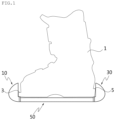
- FIG. 1 illustrates an embodiment of the snow sliding device according to the present invention attached to a boot 1.
- the snow sliding device according to the present invention the boot 1 can be directly attached to without a separate binding means.
- the snow sliding device according to the present invention may be used as a type of short ski, providing a structure allowing a user to easily and directly attach the boot 1 thereto to ride thereon.
- FIG. 1 illustrates the snow sliding device attached to the boot 1.
- a front portion 3 and a rear portion 5 of the boot 1 are fitted to the snow sliding device, so that the snow sliding device is integrally attached to the boot 1. In this position, the user can use the snow sliding device on snow as a transport means.
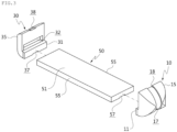
- the snow sliding device describing the snow sliding device, generally includes a first end body 10, a second end body 30, and a main body 50.
- the main body 50 is provided between the first end body 10 and the second end body 30. Theses bodies 10, 30, and 50 are connected together, thereby providing a single snow sliding device.
- Both ends of the boot 1 worn by the user are fastened to the first end body 10 and the second end body 30, respectively.
- one end is fastened to the first end body 10
- the other end is fastened to the second end body 30.
- both ends of the boot 1 are fastened to the first end body 10 and the second end body 30, the user can move on snow using the snow sliding device.
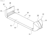
- the first end body 10 and the second end body 30 include connecting portions 11 and 31 connected to the main body 50 and outer portions 15 and 35 perpendicularly extending from the connecting portion 11 and 31 to form a nose and a tail, respectively. That is, the first end body 10 and the second end body 30 have the nose and the tail, respectively.
- Each of the first end body 10 and the second end body 30 has a coupling recess 32 into which a corresponding end of both ends of the boot 1 is fitted.
- the first end body 10 and the second end body 30 may be configured to have symmetrical shapes.
- the coupling recess 32 of the first end body 10 is not shown in FIGS. 2 and 3 .
- an outer surface thereof i.e. the outer portion 15 or 35, is provided in the shape of a curved surface.
- both the first end body 10 and the second end body 30 have curved outer surfaces. This configuration allows the user, riding on the snow sliding device, to erect the snow sliding device so that the curved outer surface of the first end body 10 or the second end body 30 is brought into contact with the ground. This consequently improves sliding performance and helps the user to glide while performing a variety of maneuvers.
- a portion of the snow sliding device adjacent to the second end body 30 may be separated from a snow surface, while the outer portion 15 of the first end body 10 is in contact with the snow surface.
- a guide recess 18 or 38 is provided in the outer surface of at least one of the first end body 10 and the second end body 30.
- the guide recesses 18 and 38 may facilitate sliding of the first end body 10 or the second end body 30, when the curved outer surface thereof is in contact with the ground, or allow other components to be connected thereto.
- the connected components may be a front edge block (not shown) or a variety of Internet of things (IoT) devices, including a light-emitting diode (LED) lamp.
- IoT Internet of things
- the guide recesses 18 and 38 extend in the longitudinal direction of the snow sliding device. More specifically, as illustrated in FIG. 2 , the guide recesses 18 and 38 extend in a bot-to-bottom direction of the first end body 10. When the first end body 10 is directed toward the snow surface (bottom), the guide recesses 18 and 38 extend in a direction parallel to the longitudinal direction of snow sliding device. This can further improve the sliding performance of the snow sliding device.
- the main body 50 is provided between the first end body 10 and the second end body 30.
- the main body 50 may be regarded as connecting the first end body 10 and the second end body 30.
- the main body 50 has an edge surface 55 directed toward the snow surface (ground).
- one of several edge surfaces 55 of the main body 50 can be selectively used by changing the edge surface of the main body 50 with another edge surface.
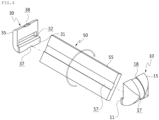
- the plurality of edge surfaces 55 of the main body 50 can be used through rotation of the main body 50. As illustrated in FIG. 4 , when the separated main body 50 is rotated 180°, the opposite surface is directed toward the ground, and the other edge surface 55 can be used. More specifically, the main body 50 is provided to be rotatable with respect to the first end body 10 and the second end body 30 about the axis of rotation extending along a line connecting the first end body 10 and the second end body 30. Reference numeral 51,151,251,351 indicates a top surface of the main body 50.
- the main body 50 is provided rotatable with respect to the first end body 10 and the second end body 30. Rotation of the main body 50 allows both the top surface and the bottom surface to be used, so that two edge surfaces can be selectively used. Accordingly, when one edge surface is worn, the other edge surface can be used, thereby increasing the longevity of the snow sliding device. In addition, the length, thickness, and the like of an effective edge can be selected by the user through replacement of the edge, thereby improving the operability of the snow sliding device.
- the main body 50 is connected to the first end body 10 and the second end body 30 in such a manner that the main body 50 can be separated from the first end body 10 and the second end body 30.
- the edge surface directed toward the ground may be changed.
- the main body 50 since the main body 50 can be completely separated from and then reconnected to the first end body 10 and the second end body 30, the main body 50 may be rotated or replaced by another main body before being reconnected to the first end body 10 and the second end body 30.
- the length of another main body is different from the length of the main body 50, the entire length of the snow sliding device is varied.
- the main body 50 may be provided as a single body or may be comprised of a plurality of separable unit bodies. When the main body 50 is comprised of the plurality of separable unit bodies, the overall length of the snow sliding device may be varied by varying the number of the unit bodies.
- a main guide 57,257,357 is provided in the bottom of the main body 50.
- the main guide 57 is recessed in the bottom, i.e. a bottom surface, of the main body 50.
- the main guide 57 extends in the longitudinal direction of the main body 50, thereby improving the sliding performance of the snow sliding device.
- the main guide 57 may be provided in a location aligned with connecting recesses 17 and 37 provided in the bottoms of the above-described guide recesses 18 and 38, such that the main guide 57 is continuous with the connecting recesses 17,117,217,317 and 37,237,337.
- a separate lower plate may be connected to the main body 50 of the snow sliding device.
- the lower plate protrudes toward the ground, thereby providing an edge surface, and is connected to the main guide 57 of the main body 50.
- the lower plate may be connected to the main body 50 by a variety of methods.
- the lower plate may be connected to the main body 50 using a fastener, such as a bolt, or may be fitted to the main body 50 by sliding.
- An edge means may be connected to the main body 50, based on a press-fitting structure.
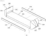
- the side edge blocks 170 extend in the longitudinal direction of the main body 150, and have a low thickness.
- the top-bottom height of the side edge blocks 170 may be the same or different from the top-bottom height of the main body 150.
- the top-bottom height of the side edge blocks 170 may be selected differently, depending on the sliding performance of the snow sliding device.
- the side edge blocks 170 may be connected to the main body 50 using a fastener, such as a bolt, or a variety of other coupling structures, such as a press-fitting structure and a coupling structure having coupling protrusions.
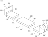
- FIG. 6 is an exploded perspective view illustrating a third embodiment of the snow sliding device according to the present invention.
- a main body 250 relatively shorter in length than the main body 50 according to either the foregoing embodiment of FIG. 2 or the foregoing embodiment of FIG. 5 .
- the main body 250 is relatively shorter in length, but connecting portions 211 and 231 of first and second end bodies 210 and 230 are provided to be relatively longer.
- the overall length of the snow sliding device may be reduced.
- the length of the snow sliding device may be changed more variously through replacement of the main body 250.
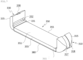
- FIG. 7 illustrates a fourth embodiment of the snow sliding device according to the present invention.
- an edge block is connected to the bottom, i.e. a bottom surface, of the snow sliding device.
- the edge block is a lower edge block 380.
- the lower edge block 380 may act to increase the overall height of the snow sliding device while providing an edge surface in the bottom of the main body 350.
- the lower edge block 380 can be fastened to the bottom of the main body 350 using a fastener or a variety of other methods, such as a slide-fitting method.
- the lower edge block 380 may have a variety of widths and heights, and may provide sliding performance required by the user through replacement.
- the boot 1 when a user, gliding on snow using a snow sliding device, intends to replace an edge surface of the snow sliding device, the boot 1 must first be detached from the snow sliding device. When a front portion 3 and a rear portion 5 of the boot 1 are separated from the first end body 10 and the second end body 30, respectively, the boot 1 is detached from the snow sliding device.
- the user separates the first end body 10 and the second end body 30 from the main body 50. Since the first end body 10 and the second end body 30 are connected to the main body 50 using a protrusion coupling structure, a coupling structure using a fastener (e.g. a bolt), a sliding coupling structure, or the like, the first end body 10 and the second end body 30 can be separated from the main body 50.
- a fastener e.g. a bolt
- a sliding coupling structure e.g. a sliding coupling structure
- the main body 50 When the main body 50 is separated, the main body 50 may be rotated before being reconnected to the first end body 10 and the second end body 30. Alternatively, the main body 50 may be replaced with another main body, which is then connected to the first end body 10 and the second end body 30. This consequently changes the edge surface rubbing against snow. When an edge is abraded, the main body may be replaced with another main body or another edge may be used, thereby increasing the longevity of the snow sliding device. In addition, the user may freely select the length, thickness, or the like of an effective edge through replacement of the edge.
Landscapes
- Footwear And Its Accessory, Manufacturing Method And Apparatuses (AREA)
- Buildings Adapted To Withstand Abnormal External Influences (AREA)
- Road Paving Structures (AREA)
Claims (10)
- Schneegleitvorrichtung, aufweisend:einen ersten Endkörper (10, 110, 210, 310), an dem ein Ende eines Stiefels (1) befestigt ist;einen zweiten Endkörper (30, 130, 230, 330), der entgegengesetzt zu dem ersten Endkörper Z p (10, 110, 210, 310) bereitgestellt ist, so dass das andere Ende des Stiefels (1) an dem zweiten Endkörper (30, 130, 230, 330) befestigt ist; undeinen Hauptkörper (50, 150, 250, 350), welcher zwischen dem ersten Endkörper (10) und dem zweiten Endkörper (30, 130, 230, 330) bereitgestellt ist, um den ersten Endkörper (10) und den zweiten Endkörper (30, 130, 230, 330) zu verbinden, wobei eine zum Boden hin gerichtete Randfläche (55, 255, 355) des Hauptkörpers (50) veränderbar ist, um selektiv verwendet zu werden,wobei der Hauptkörper (50) trennbar mit dem ersten Endkörper (10) und dem zweiten Endkörper (30) verbunden ist, und wenn eine Richtung, in welcher der Hauptkörper (50) mit dem ersten Endkörper (10) und dem zweiten Endkörper (30) verbunden ist, verändert wird, die zum Boden hin gerichtete Randfläche (55) des Hauptkörpers (50) verändert wird, undwobei zumindest einer von dem ersten Endkörper (10) und dem zweiten Endkörper (30) eine gekrümmte Fläche aufweist, von welcher ein zentraler Abschnitt parallel zu einer Längsrichtung der Schneegleitvorrichtung vorsteht.
- Die Schneegleitvorrichtung gemäß Anspruch 1, wobei der Hauptkörper (50) eingerichtet ist, um in Bezug auf den ersten Endkörper (10) und den zweiten Endkörper (30) drehbar zu sein, so dass die zum Boden hin gerichtete Randfläche (55) davon selektiv veränderbar ist.
- Schneegleitvorrichtung gemäß Anspruch 1, wobei der Hauptkörper (50) einen unteren Randblock (380) hat, welcher mit ihm verbunden ist, wobei der untere Randblock (380) in Richtung des Bodens vorsteht, wodurch eine Randfläche (55) bereitgestellt ist.
- Schneegleitvorrichtung gemäß Anspruch 1, wobei eine Breite des Hauptkörpers (50) schmaler ist als eine Breite entweder des ersten Endkörpers (10) oder des zweiten Endkörpers (30), so dass beide Seitenflächen des Hauptkörpers (50) weiter nach innen ausgespart sind als der erste Endkörper (10) und der zweite Endkörper (30), wodurch ausgesparte Flächen bereitgestellt sind, an welche Randblöcke (170) selektiv gekuppelt sind.
- Schneegleitvorrichtung gemäß Anspruch 1, wobei jeder von dem ersten Endkörper (10) und dem zweiten Endkörper (30) aufweist: einen Verbindungsabschnitt (11, 111, 211, 311, 31, 131, 231, 331), welcher mit dem Hauptkörper (50) verbunden ist, und einen äußeren Abschnitt (15, 35), der sich senkrecht von dem Verbindungsabschnitt (211, 231) aus erstreckt, wodurch entweder eine Nase oder ein Endstück bereitgestellt ist.
- Schneegleitvorrichtung gemäß Anspruch 1, wobei der Hauptkörper (50) einen einzigen Körper oder eine Mehrzahl von trennbaren Einheit-Körpern aufweist.
- Schneegleitvorrichtung gemäß Anspruch 1, wobei der erste Endkörper (10) und der zweite Endkörper (30) eine Nase und ein Endstück bereitstellen und Kupplungsaussparungen (32) aufweisen, in welche in zugeordneter Weise das eine und das andere Ende des Stiefels (1) eingesetzt sind.
- Schneegleitvorrichtung gemäß Anspruch 1, wobei der erste Endkörper (10) und der zweite Endkörper (30) symmetrische Formen haben.
- Schneegleitvorrichtung gemäß Anspruch 1, wobei eine Führungsaussparung (18, 38) in einer äußeren Fläche von zumindest einem von dem ersten Endkörper (10) und dem zweiten Endkörper (30) bereitgestellt ist.
- Schneegleitvorrichtung gemäß Anspruch 9, wobei eine Hauptführung (57) in eine Bodenfläche des Hauptkörpers (50) eingelassen ist, wobei die Hauptführung (57) mit der Führungsaussparung (18, 38) korrespondiert, welche in zumindest einem von dem ersten Endkörper (10) und dem zweiten Endkörper (30) bereitgestellt ist.
Priority Applications (1)
| Application Number | Priority Date | Filing Date | Title |
|---|---|---|---|
| SI201831218T SI3586932T1 (sl) | 2017-02-21 | 2018-02-21 | Naprava za drsenje po snegu |
Applications Claiming Priority (2)
| Application Number | Priority Date | Filing Date | Title |
|---|---|---|---|
| KR1020170023135A KR101923575B1 (ko) | 2017-02-21 | 2017-02-21 | 스노우 슬라이딩 장치 |
| PCT/KR2018/002095 WO2018155887A1 (ko) | 2017-02-21 | 2018-02-21 | 스노우 슬라이딩 장치 |
Publications (3)
| Publication Number | Publication Date |
|---|---|
| EP3586932A1 EP3586932A1 (de) | 2020-01-01 |
| EP3586932A4 EP3586932A4 (de) | 2020-12-23 |
| EP3586932B1 true EP3586932B1 (de) | 2024-12-25 |
Family
ID=63252892
Family Applications (1)
| Application Number | Title | Priority Date | Filing Date |
|---|---|---|---|
| EP18757479.3A Active EP3586932B1 (de) | 2017-02-21 | 2018-02-21 | Schneegleitvorrichtung |
Country Status (7)
| Country | Link |
|---|---|
| US (1) | US10441871B2 (de) |
| EP (1) | EP3586932B1 (de) |
| KR (1) | KR101923575B1 (de) |
| CN (1) | CN108778432B (de) |
| CA (1) | CA3053752C (de) |
| SI (1) | SI3586932T1 (de) |
| WO (1) | WO2018155887A1 (de) |
Families Citing this family (1)
| Publication number | Priority date | Publication date | Assignee | Title |
|---|---|---|---|---|
| CN113018832A (zh) * | 2021-04-28 | 2021-06-25 | 明长城 | 一种冰雪两用多功能滑行装置 |
Family Cites Families (12)
| Publication number | Priority date | Publication date | Assignee | Title |
|---|---|---|---|---|
| DE3442292A1 (de) * | 1984-11-20 | 1986-05-22 | Franz Dipl.-Ing. Wilhelm (FH), 8000 München | Gleitschuh, ein schifoermiges geraet |
| US5398957A (en) * | 1993-02-26 | 1995-03-21 | Morning Sun, Inc. | Recreational boot length ski device |
| US20020017771A1 (en) * | 2000-02-29 | 2002-02-14 | Mcmanus John H. | Multi-purpose combination snowshoe/ski |
| US7681904B2 (en) * | 2002-08-02 | 2010-03-23 | Lane Ekberg | Configurable snowshoe and ski device |
| AT500213B1 (de) * | 2003-04-23 | 2007-09-15 | Atomic Austria Gmbh | Schi |
| KR100588052B1 (ko) * | 2003-12-31 | 2006-06-14 | 최원규 | 스노우 스케이트 |
| CA2574753A1 (en) * | 2007-01-19 | 2008-07-19 | Multimatic Inc. | Replaceable blade skate |
| DE202009019109U1 (de) * | 2008-02-29 | 2016-09-05 | G3 Genuine Guide Gear Inc. | Ferseneinheit für Tourenskibindung |
| KR200445532Y1 (ko) * | 2008-10-28 | 2009-08-06 | 이지하 | 철조(凸彫)형 마운트 조립부가 형성된 스키에이트, 스키 및스노우보드 |
| KR100995406B1 (ko) | 2009-07-09 | 2010-11-19 | 김상우 | 스노우 웨이크보드 데크 |
| KR20140057461A (ko) * | 2012-10-29 | 2014-05-13 | 문종훈 | 복수개의 블레이드가 곡면을 이루면서 나란히 배치된 스케이트용 블레이드 조립체 및 이를 구비한 스케이트 |
| KR101636887B1 (ko) * | 2014-06-30 | 2016-07-07 | 이지하 | 길이가변형 스노우 슬라이딩 장치 |
-
2017
- 2017-02-21 KR KR1020170023135A patent/KR101923575B1/ko active Active
-
2018
- 2018-02-21 CA CA3053752A patent/CA3053752C/en active Active
- 2018-02-21 EP EP18757479.3A patent/EP3586932B1/de active Active
- 2018-02-21 CN CN201880001282.3A patent/CN108778432B/zh active Active
- 2018-02-21 WO PCT/KR2018/002095 patent/WO2018155887A1/ko not_active Ceased
- 2018-02-21 US US16/083,690 patent/US10441871B2/en active Active
- 2018-02-21 SI SI201831218T patent/SI3586932T1/sl unknown
Also Published As
| Publication number | Publication date |
|---|---|
| WO2018155887A1 (ko) | 2018-08-30 |
| US20190070482A1 (en) | 2019-03-07 |
| KR101923575B1 (ko) | 2018-11-29 |
| EP3586932A1 (de) | 2020-01-01 |
| KR20180096423A (ko) | 2018-08-29 |
| CA3053752A1 (en) | 2018-08-30 |
| CN108778432A (zh) | 2018-11-09 |
| CN108778432B (zh) | 2020-03-03 |
| CA3053752C (en) | 2022-05-03 |
| US10441871B2 (en) | 2019-10-15 |
| SI3586932T1 (sl) | 2025-04-30 |
| EP3586932A4 (de) | 2020-12-23 |
Similar Documents
| Publication | Publication Date | Title |
|---|---|---|
| US20080272575A1 (en) | Snowboard | |
| SE506283C2 (sv) | Skridskoskena | |
| US8939463B2 (en) | Individual snowboards for each foot | |
| CA2850113A1 (en) | Ice skate attachment | |
| EP3586932B1 (de) | Schneegleitvorrichtung | |
| US7445227B2 (en) | Ski with improved edging characteristics | |
| US8899612B2 (en) | Sports article with a guide element for footwear | |
| EP2921208B1 (de) | Schneegleitvorrichtung | |
| KR101535793B1 (ko) | 다기능 블록 및 이를 구비한 스노우 슬라이딩 장치 | |
| KR101636887B1 (ko) | 길이가변형 스노우 슬라이딩 장치 | |
| RU103485U1 (ru) | Лыжное крепление | |
| US10946264B2 (en) | Reduced contact length snowboards and splitboards | |
| EP1848515B1 (de) | Snowboard und skier für den gebrauch in pulverschnee | |
| KR20090011136U (ko) | 개량형 휨 보강플레이트가 구비된 스노우보드 | |
| US8596667B1 (en) | Ski with side wall cutouts | |
| KR101535794B1 (ko) | 스노우 슬라이딩 장치 | |
| US20120292886A1 (en) | Edges for skis, snowboards and ice skates | |
| US7048634B1 (en) | Skateboard rail | |
| US20150272267A1 (en) | Sole for ski boot | |
| EP2253236A1 (de) | Tragflügelschuh | |
| KR200384647Y1 (ko) | 두발 고정식 스키용 보드 | |
| RU2057564C1 (ru) | Лезвие для конька айсборда | |
| KR200239874Y1 (ko) | 스키겸용 스노우보드 | |
| KR100430441B1 (ko) | 스키겸용 스노우보드 | |
| KR200353330Y1 (ko) | 인라인스케이트용 프레임 |
Legal Events
| Date | Code | Title | Description |
|---|---|---|---|
| STAA | Information on the status of an ep patent application or granted ep patent |
Free format text: STATUS: THE INTERNATIONAL PUBLICATION HAS BEEN MADE |
|
| PUAI | Public reference made under article 153(3) epc to a published international application that has entered the european phase |
Free format text: ORIGINAL CODE: 0009012 |
|
| STAA | Information on the status of an ep patent application or granted ep patent |
Free format text: STATUS: REQUEST FOR EXAMINATION WAS MADE |
|
| 17P | Request for examination filed |
Effective date: 20190816 |
|
| AK | Designated contracting states |
Kind code of ref document: A1 Designated state(s): AL AT BE BG CH CY CZ DE DK EE ES FI FR GB GR HR HU IE IS IT LI LT LU LV MC MK MT NL NO PL PT RO RS SE SI SK SM TR |
|
| AX | Request for extension of the european patent |
Extension state: BA ME |
|
| DAV | Request for validation of the european patent (deleted) | ||
| DAX | Request for extension of the european patent (deleted) | ||
| A4 | Supplementary search report drawn up and despatched |
Effective date: 20201124 |
|
| RIC1 | Information provided on ipc code assigned before grant |
Ipc: A63C 5/048 20060101AFI20201118BHEP Ipc: A63C 5/052 20060101ALI20201118BHEP Ipc: A63C 5/02 20060101ALI20201118BHEP Ipc: A63C 5/04 20060101ALI20201118BHEP Ipc: A63C 5/12 20060101ALI20201118BHEP |
|
| GRAP | Despatch of communication of intention to grant a patent |
Free format text: ORIGINAL CODE: EPIDOSNIGR1 |
|
| STAA | Information on the status of an ep patent application or granted ep patent |
Free format text: STATUS: GRANT OF PATENT IS INTENDED |
|
| RIC1 | Information provided on ipc code assigned before grant |
Ipc: A63C 5/025 20060101ALI20240424BHEP Ipc: A63C 5/12 20060101ALI20240424BHEP Ipc: A63C 5/052 20060101ALI20240424BHEP Ipc: A63C 5/04 20060101ALI20240424BHEP Ipc: A63C 5/02 20060101ALI20240424BHEP Ipc: A63C 5/048 20060101AFI20240424BHEP |
|
| INTG | Intention to grant announced |
Effective date: 20240514 |
|
| GRAJ | Information related to disapproval of communication of intention to grant by the applicant or resumption of examination proceedings by the epo deleted |
Free format text: ORIGINAL CODE: EPIDOSDIGR1 |
|
| STAA | Information on the status of an ep patent application or granted ep patent |
Free format text: STATUS: REQUEST FOR EXAMINATION WAS MADE |
|
| GRAP | Despatch of communication of intention to grant a patent |
Free format text: ORIGINAL CODE: EPIDOSNIGR1 |
|
| STAA | Information on the status of an ep patent application or granted ep patent |
Free format text: STATUS: GRANT OF PATENT IS INTENDED |
|
| INTC | Intention to grant announced (deleted) | ||
| INTG | Intention to grant announced |
Effective date: 20241014 |
|
| GRAS | Grant fee paid |
Free format text: ORIGINAL CODE: EPIDOSNIGR3 |
|
| GRAA | (expected) grant |
Free format text: ORIGINAL CODE: 0009210 |
|
| STAA | Information on the status of an ep patent application or granted ep patent |
Free format text: STATUS: THE PATENT HAS BEEN GRANTED |
|
| AK | Designated contracting states |
Kind code of ref document: B1 Designated state(s): AL AT BE BG CH CY CZ DE DK EE ES FI FR GB GR HR HU IE IS IT LI LT LU LV MC MK MT NL NO PL PT RO RS SE SI SK SM TR |
|
| REG | Reference to a national code |
Ref country code: GB Ref legal event code: FG4D |
|
| REG | Reference to a national code |
Ref country code: CH Ref legal event code: EP |
|
| REG | Reference to a national code |
Ref country code: DE Ref legal event code: R096 Ref document number: 602018077925 Country of ref document: DE |
|
| REG | Reference to a national code |
Ref country code: IE Ref legal event code: FG4D |
|
| REG | Reference to a national code |
Ref country code: LT Ref legal event code: MG9D |
|
| PG25 | Lapsed in a contracting state [announced via postgrant information from national office to epo] |
Ref country code: HR Free format text: LAPSE BECAUSE OF FAILURE TO SUBMIT A TRANSLATION OF THE DESCRIPTION OR TO PAY THE FEE WITHIN THE PRESCRIBED TIME-LIMIT Effective date: 20241225 |
|
| PGFP | Annual fee paid to national office [announced via postgrant information from national office to epo] |
Ref country code: DE Payment date: 20250220 Year of fee payment: 8 |
|
| PG25 | Lapsed in a contracting state [announced via postgrant information from national office to epo] |
Ref country code: FI Free format text: LAPSE BECAUSE OF FAILURE TO SUBMIT A TRANSLATION OF THE DESCRIPTION OR TO PAY THE FEE WITHIN THE PRESCRIBED TIME-LIMIT Effective date: 20241225 |
|
| PG25 | Lapsed in a contracting state [announced via postgrant information from national office to epo] |
Ref country code: BG Free format text: LAPSE BECAUSE OF FAILURE TO SUBMIT A TRANSLATION OF THE DESCRIPTION OR TO PAY THE FEE WITHIN THE PRESCRIBED TIME-LIMIT Effective date: 20241225 |
|
| PGFP | Annual fee paid to national office [announced via postgrant information from national office to epo] |
Ref country code: NO Payment date: 20250305 Year of fee payment: 8 |
|
| PG25 | Lapsed in a contracting state [announced via postgrant information from national office to epo] |
Ref country code: LV Free format text: LAPSE BECAUSE OF FAILURE TO SUBMIT A TRANSLATION OF THE DESCRIPTION OR TO PAY THE FEE WITHIN THE PRESCRIBED TIME-LIMIT Effective date: 20241225 Ref country code: GR Free format text: LAPSE BECAUSE OF FAILURE TO SUBMIT A TRANSLATION OF THE DESCRIPTION OR TO PAY THE FEE WITHIN THE PRESCRIBED TIME-LIMIT Effective date: 20250326 |
|
| PGFP | Annual fee paid to national office [announced via postgrant information from national office to epo] |
Ref country code: AT Payment date: 20250318 Year of fee payment: 8 Ref country code: CH Payment date: 20250325 Year of fee payment: 8 Ref country code: SI Payment date: 20250226 Year of fee payment: 8 |
|
| PGFP | Annual fee paid to national office [announced via postgrant information from national office to epo] |
Ref country code: FR Payment date: 20250227 Year of fee payment: 8 Ref country code: CZ Payment date: 20250220 Year of fee payment: 8 |
|
| PGFP | Annual fee paid to national office [announced via postgrant information from national office to epo] |
Ref country code: IT Payment date: 20250324 Year of fee payment: 8 Ref country code: GB Payment date: 20250324 Year of fee payment: 8 |
|
| PG25 | Lapsed in a contracting state [announced via postgrant information from national office to epo] |
Ref country code: RS Free format text: LAPSE BECAUSE OF FAILURE TO SUBMIT A TRANSLATION OF THE DESCRIPTION OR TO PAY THE FEE WITHIN THE PRESCRIBED TIME-LIMIT Effective date: 20250325 |
|
| REG | Reference to a national code |
Ref country code: NL Ref legal event code: MP Effective date: 20241225 |
|
| PG25 | Lapsed in a contracting state [announced via postgrant information from national office to epo] |
Ref country code: NL Free format text: LAPSE BECAUSE OF FAILURE TO SUBMIT A TRANSLATION OF THE DESCRIPTION OR TO PAY THE FEE WITHIN THE PRESCRIBED TIME-LIMIT Effective date: 20241225 |
|
| PG25 | Lapsed in a contracting state [announced via postgrant information from national office to epo] |
Ref country code: SM Free format text: LAPSE BECAUSE OF FAILURE TO SUBMIT A TRANSLATION OF THE DESCRIPTION OR TO PAY THE FEE WITHIN THE PRESCRIBED TIME-LIMIT Effective date: 20241225 |
|
| PG25 | Lapsed in a contracting state [announced via postgrant information from national office to epo] |
Ref country code: PL Free format text: LAPSE BECAUSE OF FAILURE TO SUBMIT A TRANSLATION OF THE DESCRIPTION OR TO PAY THE FEE WITHIN THE PRESCRIBED TIME-LIMIT Effective date: 20241225 |
|
| PG25 | Lapsed in a contracting state [announced via postgrant information from national office to epo] |
Ref country code: ES Free format text: LAPSE BECAUSE OF FAILURE TO SUBMIT A TRANSLATION OF THE DESCRIPTION OR TO PAY THE FEE WITHIN THE PRESCRIBED TIME-LIMIT Effective date: 20241225 |
|
| PG25 | Lapsed in a contracting state [announced via postgrant information from national office to epo] |
Ref country code: IS Free format text: LAPSE BECAUSE OF FAILURE TO SUBMIT A TRANSLATION OF THE DESCRIPTION OR TO PAY THE FEE WITHIN THE PRESCRIBED TIME-LIMIT Effective date: 20250425 |
|
| PG25 | Lapsed in a contracting state [announced via postgrant information from national office to epo] |
Ref country code: PT Free format text: LAPSE BECAUSE OF FAILURE TO SUBMIT A TRANSLATION OF THE DESCRIPTION OR TO PAY THE FEE WITHIN THE PRESCRIBED TIME-LIMIT Effective date: 20250428 |
|
| PG25 | Lapsed in a contracting state [announced via postgrant information from national office to epo] |
Ref country code: EE Free format text: LAPSE BECAUSE OF FAILURE TO SUBMIT A TRANSLATION OF THE DESCRIPTION OR TO PAY THE FEE WITHIN THE PRESCRIBED TIME-LIMIT Effective date: 20241225 |
|
| PG25 | Lapsed in a contracting state [announced via postgrant information from national office to epo] |
Ref country code: RO Free format text: LAPSE BECAUSE OF FAILURE TO SUBMIT A TRANSLATION OF THE DESCRIPTION OR TO PAY THE FEE WITHIN THE PRESCRIBED TIME-LIMIT Effective date: 20241225 |
|
| PG25 | Lapsed in a contracting state [announced via postgrant information from national office to epo] |
Ref country code: SK Free format text: LAPSE BECAUSE OF FAILURE TO SUBMIT A TRANSLATION OF THE DESCRIPTION OR TO PAY THE FEE WITHIN THE PRESCRIBED TIME-LIMIT Effective date: 20241225 |
|
| PG25 | Lapsed in a contracting state [announced via postgrant information from national office to epo] |
Ref country code: SE Free format text: LAPSE BECAUSE OF FAILURE TO SUBMIT A TRANSLATION OF THE DESCRIPTION OR TO PAY THE FEE WITHIN THE PRESCRIBED TIME-LIMIT Effective date: 20241225 |
|
| PG25 | Lapsed in a contracting state [announced via postgrant information from national office to epo] |
Ref country code: MC Free format text: LAPSE BECAUSE OF FAILURE TO SUBMIT A TRANSLATION OF THE DESCRIPTION OR TO PAY THE FEE WITHIN THE PRESCRIBED TIME-LIMIT Effective date: 20241225 |
|
| REG | Reference to a national code |
Ref country code: DE Ref legal event code: R097 Ref document number: 602018077925 Country of ref document: DE |
|
| PG25 | Lapsed in a contracting state [announced via postgrant information from national office to epo] |
Ref country code: DK Free format text: LAPSE BECAUSE OF FAILURE TO SUBMIT A TRANSLATION OF THE DESCRIPTION OR TO PAY THE FEE WITHIN THE PRESCRIBED TIME-LIMIT Effective date: 20241225 |
|
| PG25 | Lapsed in a contracting state [announced via postgrant information from national office to epo] |
Ref country code: LU Free format text: LAPSE BECAUSE OF NON-PAYMENT OF DUE FEES Effective date: 20250221 |
|
| PLBE | No opposition filed within time limit |
Free format text: ORIGINAL CODE: 0009261 |
|
| STAA | Information on the status of an ep patent application or granted ep patent |
Free format text: STATUS: NO OPPOSITION FILED WITHIN TIME LIMIT |
|
| 26N | No opposition filed |
Effective date: 20250926 |
|
| REG | Reference to a national code |
Ref country code: BE Ref legal event code: MM Effective date: 20250228 |
|
| PG25 | Lapsed in a contracting state [announced via postgrant information from national office to epo] |
Ref country code: BE Free format text: LAPSE BECAUSE OF NON-PAYMENT OF DUE FEES Effective date: 20250228 |
|
| PG25 | Lapsed in a contracting state [announced via postgrant information from national office to epo] |
Ref country code: IE Free format text: LAPSE BECAUSE OF NON-PAYMENT OF DUE FEES Effective date: 20250221 |
|
| REG | Reference to a national code |
Ref country code: AT Ref legal event code: UEP Ref document number: 1753709 Country of ref document: AT Kind code of ref document: T Effective date: 20241225 |