EP3586987A1 - Bobinage d'une bande métallique et installation de bobinage - Google Patents
Bobinage d'une bande métallique et installation de bobinage Download PDFInfo
- Publication number
- EP3586987A1 EP3586987A1 EP18178954.6A EP18178954A EP3586987A1 EP 3586987 A1 EP3586987 A1 EP 3586987A1 EP 18178954 A EP18178954 A EP 18178954A EP 3586987 A1 EP3586987 A1 EP 3586987A1
- Authority
- EP
- European Patent Office
- Prior art keywords
- coil
- reel
- mandrel
- coiler
- reeling
- Prior art date
- Legal status (The legal status is an assumption and is not a legal conclusion. Google has not performed a legal analysis and makes no representation as to the accuracy of the status listed.)
- Withdrawn
Links
Images



Classifications
-
- B—PERFORMING OPERATIONS; TRANSPORTING
- B21—MECHANICAL METAL-WORKING WITHOUT ESSENTIALLY REMOVING MATERIAL; PUNCHING METAL
- B21C—MANUFACTURE OF METAL SHEETS, WIRE, RODS, TUBES, PROFILES OR LIKE SEMI-MANUFACTURED PRODUCTS OTHERWISE THAN BY ROLLING; AUXILIARY OPERATIONS USED IN CONNECTION WITH METAL-WORKING WITHOUT ESSENTIALLY REMOVING MATERIAL
- B21C47/00—Winding-up, coiling or winding-off metal wire, metal band or other flexible metal material characterised by features relevant to metal processing only
- B21C47/02—Winding-up or coiling
- B21C47/04—Winding-up or coiling on or in reels or drums, without using a moving guide
- B21C47/06—Winding-up or coiling on or in reels or drums, without using a moving guide with loaded rollers, bolts, or equivalent means holding the material on the reel or drum
- B21C47/063—Winding-up or coiling on or in reels or drums, without using a moving guide with loaded rollers, bolts, or equivalent means holding the material on the reel or drum with pressure rollers only
-
- B—PERFORMING OPERATIONS; TRANSPORTING
- B21—MECHANICAL METAL-WORKING WITHOUT ESSENTIALLY REMOVING MATERIAL; PUNCHING METAL
- B21C—MANUFACTURE OF METAL SHEETS, WIRE, RODS, TUBES, PROFILES OR LIKE SEMI-MANUFACTURED PRODUCTS OTHERWISE THAN BY ROLLING; AUXILIARY OPERATIONS USED IN CONNECTION WITH METAL-WORKING WITHOUT ESSENTIALLY REMOVING MATERIAL
- B21C47/00—Winding-up, coiling or winding-off metal wire, metal band or other flexible metal material characterised by features relevant to metal processing only
- B21C47/24—Transferring coils to or from winding apparatus or to or from operative position therein; Preventing uncoiling during transfer
-
- B—PERFORMING OPERATIONS; TRANSPORTING
- B21—MECHANICAL METAL-WORKING WITHOUT ESSENTIALLY REMOVING MATERIAL; PUNCHING METAL
- B21C—MANUFACTURE OF METAL SHEETS, WIRE, RODS, TUBES, PROFILES OR LIKE SEMI-MANUFACTURED PRODUCTS OTHERWISE THAN BY ROLLING; AUXILIARY OPERATIONS USED IN CONNECTION WITH METAL-WORKING WITHOUT ESSENTIALLY REMOVING MATERIAL
- B21C47/00—Winding-up, coiling or winding-off metal wire, metal band or other flexible metal material characterised by features relevant to metal processing only
- B21C47/28—Drums or other coil-holders
- B21C47/30—Drums or other coil-holders expansible or contractible
-
- B—PERFORMING OPERATIONS; TRANSPORTING
- B21—MECHANICAL METAL-WORKING WITHOUT ESSENTIALLY REMOVING MATERIAL; PUNCHING METAL
- B21C—MANUFACTURE OF METAL SHEETS, WIRE, RODS, TUBES, PROFILES OR LIKE SEMI-MANUFACTURED PRODUCTS OTHERWISE THAN BY ROLLING; AUXILIARY OPERATIONS USED IN CONNECTION WITH METAL-WORKING WITHOUT ESSENTIALLY REMOVING MATERIAL
- B21C47/00—Winding-up, coiling or winding-off metal wire, metal band or other flexible metal material characterised by features relevant to metal processing only
- B21C47/32—Tongs or gripping means specially adapted for reeling operations
- B21C47/326—Devices for pressing the end of the material being wound against the cylindrical wall of the reel or bobbin
Definitions
- the invention relates to a method and a reel system for reeling a metallic strip, the strip being coiled in a reel stand on a reel mandrel to form a coil.
- Metallic strips such as steel strips are usually coiled into so-called coils for transport and storage. Restoring forces act in the coiled strip, which can lead to uncoiling, that is, to the coil opening.
- Various methods and devices are known for reeling a tape into a coil and securing it against uncoiling.
- EP 2 648 860 B1 discloses an apparatus and a method for handling a metal strip, wherein a coil is pulled off a stationary coiler mandrel with the aid of a collar extension carriage and is thereby secured against popping open by a first hold-down arm and by a second hold-down arm which engages in the coil eye of the coil.
- EP 2 644 290 A1 discloses a reel method and a reel system for a strip, the strip being coiled in a reel device about a coil axis to form a coil with a number of turns lying radially one above the other.
- the coil is still secured in the reel device by unfastening the radially outermost turn by means of a securing device relative to at least one turn located further inside.
- the coil, which is secured against uncoiling, is removed from the reel device together with the securing device by means of a conveying device.
- US 3,527,425 A discloses a tensioning reel with an expandable reel mandrel for reeling a metallic band to a coil.
- the reel mandrel can be moved in the axial direction along a telescopic drive shaft by means of a slide on rails in order to pull the reel mandrel away from the coil, the actual drive remaining spatially fixed.
- the invention has for its object to provide a method and a reel system for reeling a metallic strip into a coil, which are improved in particular with regard to securing the coil against uncoiling.
- the object is achieved by a method with the features of claim 1 and a reel system with the features of claim 8.
- the strip is coiled in a reel stand onto a reel mandrel to form a coil with a coil eye through which the reel mandrel runs and is pressed against the reel mandrel by at least one pressing element during the reeling.
- the coiler mandrel is at least partially moved out of the coil eye of the coil along a longitudinal axis of the coiler mandrel, the coil being held in position by the at least one pressing element and secured against uncoiling.
- the coil is secured against uncoiling by a securing device, and the coil secured against uncoiling by the securing device is released by the at least one pressing element and transported away from the reel stand.
- the invention thus provides a movable reel mandrel which is completely or partially moved out of the coil eye of the coil after the reel has been reeled. So it becomes, for example, different from that EP 2 648 860 B1 known prior art, not the coil is pulled from the coiler mandrel, but the coiler mandrel is pulled out of the coil.
- the coil is temporarily held by at least one pressing element, which is also used for reeling the strip, and is secured against uncoiling.
- the coil is then secured against uncoiling by a safety device. In this way, the coil is secured against uncoiling after coiling and during removal.
- One embodiment of the invention provides that the securing device exerts a securing force directed radially outward from the coil eye onto the coil.
- the securing device according to this embodiment of the invention acts on the coil from the coil eye and exerts a radially outward securing force on the coil.
- This embodiment of the invention takes advantage of the fact that the coil eye is free after the reel mandrel has been pulled out and the securing device can therefore engage the coil from the coil eye. Securing the coil against uncoiling from the coil eye saves space compared to a fuse that ripens on an outer circumference of the coil, since no components of the securing device have to be positioned on the outside of the coil.
- a further embodiment of the invention provides that the coil is transported out of the reel stand on an extension carriage.
- the coil is stored on at least one support of the extension cart during removal from the reel stand and is pressed against the at least one support by the securing device. This enables the coil to be secured against uncoiling when the coil is transported away on an extension cart.
- each pressure element is designed as a pressure roller which is placed against the coil in order to hold the coil and to prevent it from being unwound.
- Pressure rollers are particularly suitable pressure elements since they can also advantageously support the winding of the strip, in particular if they are designed to be rotatable about their longitudinal axes.
- a further embodiment of the invention provides that the reel mandrel has a variable diameter in a plane perpendicular to its longitudinal axis and the diameter of the reel mandrel is reduced before and when the reel mandrel is moved out of the coil eye.
- the reduction in the diameter of the reel mandrel advantageously simplifies the removal of the reel mandrel from the coil eye of the coil, since it avoids or at least reduces friction between the reel mandrel and the coil during the removal of the reel mandrel from the coil eye.
- a further embodiment of the invention provides that the reel mandrel is rotated about its longitudinal axis by a motor via a gear during reeling and that the motor and the gear are moved together with the reel mandrel when the reel mandrel is moved out of the coil eye.
- the common movement of the reel mandrel, the motor and the gearbox enables the transmission of higher torques compared to a fixed arrangement of the motor and the gearbox, since no telescopic drive shaft has to be provided in order to drive the reel mandrel. This makes it possible, in particular, to reel strips that are made from higher-strength materials and / or to produce coils with higher coil weights.
- a reel system according to the invention for carrying out the method according to the invention comprises a reel stand in which the strip can be reeled to the coil, a reel mandrel which is between a first end position in which it is moved into the reel stand and a second end position, in which it has at least partially moved out of the reel stand, can be moved along its longitudinal axis, at least one pressing element which can be pressed against the coil in the reel stand, in order to press the strip onto the reel mandrel during reeling and the coil in its after reeling Hold position and secure against uncoiling, and a safety device through which the coil can be secured against uncoiling while the coil is being transported out of the reel stand.
- a reel system according to the invention enables the method according to the invention to be carried out.
- the advantages of a reel system according to the invention therefore correspond to the advantages of the method according to the invention already mentioned above and are not mentioned again separately here.
- An embodiment of the reel system according to the invention provides that the securing device has a hold-down arm which can be moved into the coil eye and with which a securing force directed radially outward from the coil eye can be exerted on the coil.
- This configuration of the reel system enables the above-mentioned space-saving securing of the coil from the coil eye.
- the securing device can have an adjusting arm which can be adjusted against an outer surface of the coil and with which a securing force directed towards the coil eye can be exerted on the coil.
- This embodiment of the reel system according to the invention can be advantageous, for example, if a hold-down arm that can be retracted into the coil eye is not sufficient to secure the coil or the reel system already has a positioning arm that can be adjusted to an outer surface of the coil and that can be used to secure the coil.
- a further embodiment of the reel system according to the invention provides an extension carriage for removing the coil from the Reel stand in front.
- the securing device can be arranged on the exit carriage. The arrangement of the securing device on the extension carriage enables a particularly space-saving and efficient execution of the securing device, since no separate moving device has to be provided for the securing device.
- a further embodiment of the reel system according to the invention provides a motor and a transmission with which the reel mandrel can be rotated about its longitudinal axis and which can be moved together with the reel mandrel.
- a further embodiment of the coiler system according to the invention provides that the coiler mandrel can be expanded in a plane perpendicular to its longitudinal axis and the coiler system has a spreading device with which the coiler mandrel can be expanded. In particular, the spreading device can be moved together with the coiler mandrel.
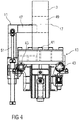
- the Figures 1 to 4 show an embodiment of a reel system 1 for reeling a metallic strip into a coil 3.
- the reel system 1 has, inter alia, a reel stand 5, a reel mandrel 7, a plurality of pressing elements 9, a securing device 11 and an extension carriage 13.
- the reel mandrel 7 can be moved along a longitudinal axis 15 of the reel mandrel 7 between a first end position in which it has been moved into the reel stand 5 and a second end position in which it has partially moved out of the reel stand 5.
- the Figures 1 and 2 each show a partially sectioned illustration of the reel system 1 without the safety device 11 and the extension carriage 13, wherein Figure 1 shows the coiler mandrel 7 in its first end position and Figure 2 shows the reel mandrel 7 in its second end position.
- the Figures 3 and 4 show the coil 3, the safety device 11 and the extension carriage 13 each in a sectional view, the sectional plane of the Figure 3 is perpendicular to a coil axis 17 of the coil 3 and the cutting plane of the Figure 3 the coil axis 17 contains.
- the reel mandrel 7 can be rotated by a motor 21 about its longitudinal axis 15 via a gear 19. Furthermore, the reel mandrel 7 can be expanded in a plane perpendicular to its longitudinal axis 15 by a spreading device 23. By spreading the coiler mandrel 7, the diameter of the coiler mandrel 7 is increased.
- the spreading device 23 is designed as a wedge spreading device, with which along the Longitudinal axis 15 extending longitudinal segments 25 of the reel mandrel 7 are expandable to the outside.
- the reel mandrel 7, the gear 19, the motor 21 and the spreading device 23 are arranged on a travel slide 27 which can be moved parallel to the longitudinal axis 15 of the reel mandrel 7 by a first hydraulic cylinder 29.
- a travel slide 27 which can be moved parallel to the longitudinal axis 15 of the reel mandrel 7 by a first hydraulic cylinder 29.
- Each pressure element 9 is designed as a pressure roller running parallel to the longitudinal axis 15 of the reel mandrel 7, which is arranged in the reel stand 5 and is supported by two pressure element bearings 31.
- Each pressure roller 9 is rotatable about its longitudinal axis via a cardan shaft 33 by a roller drive 35 and can be pivoted perpendicularly to its longitudinal axis by means of a second hydraulic cylinder 37 in order to press it against the coil 3 in the reel stand 5 during and after the winding of the strip.
- the reel system 1 has five pressure rollers 9.
- the pressure rollers 9 are each arranged on a positioning plate, for example, which can be pivoted by a second hydraulic cylinder 37.
- the extension carriage 13 has a plurality of supports 41 on which a coil 3 can be stored for its transport.
- the supports 41 are hydraulically displaceable vertically in order to engage them on the coil 3 from below.
- the extension carriage 13 also has four carriage wheels 43 with which the extension carriage 13 can be moved on rails 45.
- the securing device 11 is arranged on the extension carriage 13.
- the securing device 11 has a hold-down arm 47 which can be moved into the coil eye 49 of a coil 3 arranged on the extension carriage 13 and with which one is directed radially outward from the coil eye 49 Securing force can be exerted on the coil 3, which presses the coil 3 onto the supports 41 on which the coil 3 is mounted.
- the hold-down arm 47 is vertically displaceable by two third hydraulic cylinders 51 in order to adjust it to the diameter of the coil 3 and to press it onto the coil 3.
- Figure 5 shows a flowchart of an embodiment of the method according to the invention for reeling a metallic strip with a in the Figures 1 to 4 shown reel system 1.
- a first method step 61 the reel mandrel 7 is moved into the reel stand 5 by means of the travel carriage 27 driven by the first hydraulic cylinder 29 until it reaches its first end position and is spread with the spreading device 23.
- a second method step 62 the strip is coiled in the reel stand 5 onto the reel mandrel 7 to form a coil 3, the reel mandrel 7 being rotated about its longitudinal axis 15 by the motor 21 via the gear 19.
- the band is pressed by the pressure rollers 9 against the reel mandrel 7 and the pressure rollers 9 are rotated about their longitudinal axes with the roller drives 35.
- the spreading of the coiler mandrel 7 is canceled by the spreading device 23 in a third method step 63, the coil 3 being held in position by the pressure rollers 9 and secured against uncoiling.
- a fourth method step 64 the reel mandrel 7 is partially moved out of the reel stand 5 by means of the travel carriage 27 driven by the first hydraulic cylinder 29 until it reaches its second end position.
- the Coil 3 will continue to be used by Pressing elements 9 held in position and secured against uncoiling.
- a fifth method step 65 the coil 3 is stored on the extension carriage 13 and secured against uncoiling by the securing device 11.
- the extension carriage 13 is first moved to the coil 3, the hold-down arm 47 being moved into the coil eye 49 and supports 41 of the extension carriage 13 being positioned under the coil 3.
- the supports 41 are then placed against the coil 3 from below, and the coil 3 is pressed against the supports 41 by the hold-down arm 47.
- a sixth method step 66 the coil 3 is released from the pressure rollers 9, that is to say the pressure rollers 9 are pivoted away from the coil 3 by means of the second hydraulic cylinders 37.
- a seventh method step 67 the coil 3, which is secured against unwinding by the securing device 11, is transported out of the reel stand 5 with the extension carriage 13, for example in order to subsequently bind the coil 3 with strapping straps and thereby finally secure it against unwinding.
- the securing device 11 can have at least one positioning arm which can be adjusted to the outer surface of the coil 3 and with which a securing force directed towards the coil eye 49 can be exerted on the coil 3. It can further be provided that the securing device 11 is not arranged on the extension carriage 13, but can be moved separately.
- other drives For example, electric or pneumatic drives can be provided for moving the carriage 27, swiveling the pressure rollers 9 and / or adjusting the hold-down arm 47 and / or a positioning arm.
Landscapes
- Engineering & Computer Science (AREA)
- Mechanical Engineering (AREA)
- Winding, Rewinding, Material Storage Devices (AREA)
Priority Applications (2)
| Application Number | Priority Date | Filing Date | Title |
|---|---|---|---|
| EP18178954.6A EP3586987A1 (fr) | 2018-06-21 | 2018-06-21 | Bobinage d'une bande métallique et installation de bobinage |
| PCT/EP2019/061046 WO2019242920A1 (fr) | 2018-06-21 | 2019-04-30 | Enroulement d'une bande métallique et système d'enroulement |
Applications Claiming Priority (1)
| Application Number | Priority Date | Filing Date | Title |
|---|---|---|---|
| EP18178954.6A EP3586987A1 (fr) | 2018-06-21 | 2018-06-21 | Bobinage d'une bande métallique et installation de bobinage |
Publications (1)
| Publication Number | Publication Date |
|---|---|
| EP3586987A1 true EP3586987A1 (fr) | 2020-01-01 |
Family
ID=62748781
Family Applications (1)
| Application Number | Title | Priority Date | Filing Date |
|---|---|---|---|
| EP18178954.6A Withdrawn EP3586987A1 (fr) | 2018-06-21 | 2018-06-21 | Bobinage d'une bande métallique et installation de bobinage |
Country Status (2)
| Country | Link |
|---|---|
| EP (1) | EP3586987A1 (fr) |
| WO (1) | WO2019242920A1 (fr) |
Citations (9)
| Publication number | Priority date | Publication date | Assignee | Title |
|---|---|---|---|---|
| DE837382C (de) * | 1950-05-20 | 1952-04-28 | Siemag Vertriebsgesellschaft M | Metallbandhaspel mit Bundabschiebevorrichtung |
| US3527425A (en) | 1968-09-19 | 1970-09-08 | United Eng Foundry Co | Retractable tension reel |
| JPS5139555A (ja) * | 1974-10-02 | 1976-04-02 | Mitsubishi Heavy Ind Ltd | Kotaikoiruyoriirusochi |
| US4850546A (en) * | 1982-09-16 | 1989-07-25 | Lauener Engineering Ag | Appratus and method for reeling up strips |
| JPH0788551A (ja) * | 1993-09-20 | 1995-04-04 | Nippon Steel Corp | コイル体抜き出し装置 |
| JP2010155270A (ja) * | 2008-12-27 | 2010-07-15 | Jfe Steel Corp | 厚肉高強度熱延鋼板コイルの巻き取り・抜き出し方法およびその巻き取り装置 |
| JP2011020761A (ja) * | 2009-07-14 | 2011-02-03 | Mitsubishi-Hitachi Metals Machinery Inc | コイル搬送装置及びこれを利用するコイルステーション |
| EP2644290A1 (fr) | 2012-03-29 | 2013-10-02 | Siemens VAI Metals Technologies GmbH | Procédé et dispositif d'enroulement pour bande |
| EP2648860B1 (fr) | 2010-12-10 | 2015-01-07 | SMS Siemag AG | Dispositif et procédé de manipulation d'une bande métallique |
-
2018
- 2018-06-21 EP EP18178954.6A patent/EP3586987A1/fr not_active Withdrawn
-
2019
- 2019-04-30 WO PCT/EP2019/061046 patent/WO2019242920A1/fr not_active Ceased
Patent Citations (9)
| Publication number | Priority date | Publication date | Assignee | Title |
|---|---|---|---|---|
| DE837382C (de) * | 1950-05-20 | 1952-04-28 | Siemag Vertriebsgesellschaft M | Metallbandhaspel mit Bundabschiebevorrichtung |
| US3527425A (en) | 1968-09-19 | 1970-09-08 | United Eng Foundry Co | Retractable tension reel |
| JPS5139555A (ja) * | 1974-10-02 | 1976-04-02 | Mitsubishi Heavy Ind Ltd | Kotaikoiruyoriirusochi |
| US4850546A (en) * | 1982-09-16 | 1989-07-25 | Lauener Engineering Ag | Appratus and method for reeling up strips |
| JPH0788551A (ja) * | 1993-09-20 | 1995-04-04 | Nippon Steel Corp | コイル体抜き出し装置 |
| JP2010155270A (ja) * | 2008-12-27 | 2010-07-15 | Jfe Steel Corp | 厚肉高強度熱延鋼板コイルの巻き取り・抜き出し方法およびその巻き取り装置 |
| JP2011020761A (ja) * | 2009-07-14 | 2011-02-03 | Mitsubishi-Hitachi Metals Machinery Inc | コイル搬送装置及びこれを利用するコイルステーション |
| EP2648860B1 (fr) | 2010-12-10 | 2015-01-07 | SMS Siemag AG | Dispositif et procédé de manipulation d'une bande métallique |
| EP2644290A1 (fr) | 2012-03-29 | 2013-10-02 | Siemens VAI Metals Technologies GmbH | Procédé et dispositif d'enroulement pour bande |
Also Published As
| Publication number | Publication date |
|---|---|
| WO2019242920A1 (fr) | 2019-12-26 |
Similar Documents
| Publication | Publication Date | Title |
|---|---|---|
| EP2516081B1 (fr) | Support pour bobine métallique et dispositifs équipés d'un tel support | |
| EP2688691B1 (fr) | Dispositif et procédé de prélèvement d'échantillons de bandes épaisses | |
| EP2648860B1 (fr) | Dispositif et procédé de manipulation d'une bande métallique | |
| EP3061535B1 (fr) | Dispositif de bobineuse doté d'un refroidissement asymétrique de la bande bobinée | |
| EP3148720B1 (fr) | Dispositif et procédé pour enrouler un matériau sous forme de bande | |
| DE102009058875A1 (de) | Haspelvorrichtung und Verfahren zum Betreiben einer Haspelvorrichtung | |
| EP2644290A1 (fr) | Procédé et dispositif d'enroulement pour bande | |
| EP2953149B1 (fr) | Dispositif et procédé d'enroulement de tores sans magasin | |
| EP3586987A1 (fr) | Bobinage d'une bande métallique et installation de bobinage | |
| DE3927915A1 (de) | Haspeldorn mit notentspreizung fuer einen bandhaspel | |
| DE102010054142B4 (de) | Anordnung und Verfahren zur Abnahme wenigstens eines Metallbandbundes von einem Haspeldorn einer Aufwickelhaspel | |
| EP3507032B1 (fr) | Dispositif support pour un dévidoir-enrouleur et dispositif de dévidage | |
| EP1778420B1 (fr) | Installation de laminage et procede de production d'une bande metallique | |
| DE2237423A1 (de) | Rohrbaugruppe und verfahren und einrichtung zu ihrer herstellung | |
| EP4067274B1 (fr) | Manipulation sécurisée des manchons ou bobines métalliques présentant un petit diamètre extérieur sur un mandrin de bobineuse | |
| EP3052255B1 (fr) | Dispositif pour enrouler un matériau sous forme de bande afin de former une bobine | |
| EP0438674A2 (fr) | Procédé à enrouler simultanément plusieurs bandes métalliques refendues | |
| EP0909596A2 (fr) | Dispositif de déroulage de bandes | |
| DE1070576B (de) | Verfahren unid Vorrichtung zum kontinuierlichen Abhaspeln kernloser Bandbunde | |
| DE102013106274A1 (de) | Bandhaspelanordnung zum Auf- und/oder Abwickeln eines Metallbandes | |
| DE102016124372A1 (de) | Vorrichtung und Verfahren zur Bearbeitung eines Bandendes | |
| DE102024205107A1 (de) | Coilbox | |
| DE69020881T2 (de) | Abmontierbare Drahtspule. | |
| WO2015172965A1 (fr) | Maintien et transport d'au moins un ruban métallique enroulé sous forme de bobine | |
| DE102024205962A1 (de) | Vorrichtung und Verfahren zum Anwickeln von bandförmigem Walzgut auf einem Dorn oder einer Hülse einer Haspeleinrichtung |
Legal Events
| Date | Code | Title | Description |
|---|---|---|---|
| PUAI | Public reference made under article 153(3) epc to a published international application that has entered the european phase |
Free format text: ORIGINAL CODE: 0009012 |
|
| AK | Designated contracting states |
Kind code of ref document: A1 Designated state(s): AL AT BE BG CH CY CZ DE DK EE ES FI FR GB GR HR HU IE IS IT LI LT LU LV MC MK MT NL NO PL PT RO RS SE SI SK SM TR |
|
| AX | Request for extension of the european patent |
Extension state: BA ME |
|
| STAA | Information on the status of an ep patent application or granted ep patent |
Free format text: STATUS: THE APPLICATION IS DEEMED TO BE WITHDRAWN |
|
| 18D | Application deemed to be withdrawn |
Effective date: 20200702 |