EP3587092A1 - Procédé de traitement d'éléments obtenus par un processus de fabrication additive - Google Patents
Procédé de traitement d'éléments obtenus par un processus de fabrication additive Download PDFInfo
- Publication number
- EP3587092A1 EP3587092A1 EP18181048.2A EP18181048A EP3587092A1 EP 3587092 A1 EP3587092 A1 EP 3587092A1 EP 18181048 A EP18181048 A EP 18181048A EP 3587092 A1 EP3587092 A1 EP 3587092A1
- Authority
- EP
- European Patent Office
- Prior art keywords
- solvent
- polyamide
- elements
- chamber
- treatment
- Prior art date
- Legal status (The legal status is an assumption and is not a legal conclusion. Google has not performed a legal analysis and makes no representation as to the accuracy of the status listed.)
- Withdrawn
Links
- 238000000034 method Methods 0.000 title claims abstract description 100
- 239000000654 additive Substances 0.000 title claims abstract description 27
- 230000000996 additive effect Effects 0.000 title claims abstract description 27
- 238000004519 manufacturing process Methods 0.000 title claims abstract description 27
- 239000002904 solvent Substances 0.000 claims abstract description 187
- 239000007788 liquid Substances 0.000 claims abstract description 23
- BYEAHWXPCBROCE-UHFFFAOYSA-N 1,1,1,3,3,3-hexafluoropropan-2-ol Chemical compound FC(F)(F)C(O)C(F)(F)F BYEAHWXPCBROCE-UHFFFAOYSA-N 0.000 claims description 50
- 230000008569 process Effects 0.000 claims description 46
- 239000004952 Polyamide Substances 0.000 claims description 44
- 229920002647 polyamide Polymers 0.000 claims description 44
- 229920000642 polymer Polymers 0.000 claims description 37
- 239000000203 mixture Substances 0.000 claims description 34
- 239000003795 chemical substances by application Substances 0.000 claims description 24
- 238000011084 recovery Methods 0.000 claims description 13
- -1 polyethylene terephthalate Polymers 0.000 claims description 11
- 230000003746 surface roughness Effects 0.000 claims description 10
- 238000002604 ultrasonography Methods 0.000 claims description 9
- 239000004417 polycarbonate Substances 0.000 claims description 8
- 229920000515 polycarbonate Polymers 0.000 claims description 8
- 229930040373 Paraformaldehyde Natural products 0.000 claims description 7
- 238000009835 boiling Methods 0.000 claims description 7
- 229920001577 copolymer Polymers 0.000 claims description 7
- 229920003229 poly(methyl methacrylate) Polymers 0.000 claims description 7
- 229920002492 poly(sulfone) Polymers 0.000 claims description 7
- 239000004926 polymethyl methacrylate Substances 0.000 claims description 7
- 229920006324 polyoxymethylene Polymers 0.000 claims description 7
- 229920001601 polyetherimide Polymers 0.000 claims description 6
- 229920001169 thermoplastic Polymers 0.000 claims description 6
- 229920000139 polyethylene terephthalate Polymers 0.000 claims description 5
- 238000005245 sintering Methods 0.000 claims description 5
- 229920002614 Polyether block amide Polymers 0.000 claims description 4
- 239000004697 Polyetherimide Substances 0.000 claims description 4
- 239000004954 Polyphthalamide Substances 0.000 claims description 4
- PPBRXRYQALVLMV-UHFFFAOYSA-N Styrene Chemical compound C=CC1=CC=CC=C1 PPBRXRYQALVLMV-UHFFFAOYSA-N 0.000 claims description 4
- 239000004433 Thermoplastic polyurethane Substances 0.000 claims description 4
- 230000003247 decreasing effect Effects 0.000 claims description 4
- 238000001035 drying Methods 0.000 claims description 4
- 229920000747 poly(lactic acid) Polymers 0.000 claims description 4
- 229920006393 polyether sulfone Polymers 0.000 claims description 4
- 239000005020 polyethylene terephthalate Substances 0.000 claims description 4
- 229920006375 polyphtalamide Polymers 0.000 claims description 4
- 229920002803 thermoplastic polyurethane Polymers 0.000 claims description 4
- 229920002292 Nylon 6 Polymers 0.000 claims description 3
- 239000000835 fiber Substances 0.000 claims description 3
- 238000001914 filtration Methods 0.000 claims description 3
- 230000004927 fusion Effects 0.000 claims description 3
- 229920000571 Nylon 11 Polymers 0.000 claims description 2
- 229920000299 Nylon 12 Polymers 0.000 claims description 2
- 229920000572 Nylon 6/12 Polymers 0.000 claims description 2
- 229920003171 Poly (ethylene oxide) Polymers 0.000 claims description 2
- 229920000361 Poly(styrene)-block-poly(ethylene glycol) Polymers 0.000 claims description 2
- 239000004793 Polystyrene Substances 0.000 claims description 2
- 239000004676 acrylonitrile butadiene styrene Substances 0.000 claims description 2
- 125000001931 aliphatic group Chemical group 0.000 claims description 2
- 229920003231 aliphatic polyamide Polymers 0.000 claims description 2
- 239000004760 aramid Substances 0.000 claims description 2
- 229920003235 aromatic polyamide Polymers 0.000 claims description 2
- 239000004014 plasticizer Substances 0.000 claims description 2
- 239000004814 polyurethane Substances 0.000 claims description 2
- 229920002635 polyurethane Polymers 0.000 claims description 2
- 229920006012 semi-aromatic polyamide Polymers 0.000 claims description 2
- 239000004695 Polyether sulfone Substances 0.000 claims 2
- 239000003086 colorant Substances 0.000 claims 2
- NIXOWILDQLNWCW-UHFFFAOYSA-M Acrylate Chemical compound [O-]C(=O)C=C NIXOWILDQLNWCW-UHFFFAOYSA-M 0.000 claims 1
- 238000000149 argon plasma sintering Methods 0.000 claims 1
- 239000000945 filler Substances 0.000 claims 1
- 238000010309 melting process Methods 0.000 claims 1
- 239000004800 polyvinyl chloride Substances 0.000 claims 1
- 229920006345 thermoplastic polyamide Polymers 0.000 claims 1
- 239000000843 powder Substances 0.000 description 40
- 239000004566 building material Substances 0.000 description 19
- 239000000463 material Substances 0.000 description 16
- 239000000975 dye Substances 0.000 description 15
- 238000004043 dyeing Methods 0.000 description 13
- 239000010410 layer Substances 0.000 description 13
- 238000000110 selective laser sintering Methods 0.000 description 13
- 239000011877 solvent mixture Substances 0.000 description 10
- OKTJSMMVPCPJKN-UHFFFAOYSA-N Carbon Chemical compound [C] OKTJSMMVPCPJKN-UHFFFAOYSA-N 0.000 description 9
- YMWUJEATGCHHMB-UHFFFAOYSA-N Dichloromethane Chemical compound ClCCl YMWUJEATGCHHMB-UHFFFAOYSA-N 0.000 description 9
- 238000010438 heat treatment Methods 0.000 description 9
- 229910052751 metal Inorganic materials 0.000 description 8
- 239000002184 metal Substances 0.000 description 8
- BDAGIHXWWSANSR-UHFFFAOYSA-N methanoic acid Natural products OC=O BDAGIHXWWSANSR-UHFFFAOYSA-N 0.000 description 8
- 239000007787 solid Substances 0.000 description 8
- 238000013022 venting Methods 0.000 description 8
- 230000008901 benefit Effects 0.000 description 7
- 230000008016 vaporization Effects 0.000 description 7
- 239000011230 binding agent Substances 0.000 description 6
- 238000000227 grinding Methods 0.000 description 6
- 238000003801 milling Methods 0.000 description 5
- 230000005855 radiation Effects 0.000 description 5
- OSWFIVFLDKOXQC-UHFFFAOYSA-N 4-(3-methoxyphenyl)aniline Chemical compound COC1=CC=CC(C=2C=CC(N)=CC=2)=C1 OSWFIVFLDKOXQC-UHFFFAOYSA-N 0.000 description 4
- CSCPPACGZOOCGX-UHFFFAOYSA-N Acetone Chemical compound CC(C)=O CSCPPACGZOOCGX-UHFFFAOYSA-N 0.000 description 4
- 239000002253 acid Substances 0.000 description 4
- 238000003795 desorption Methods 0.000 description 4
- 235000019253 formic acid Nutrition 0.000 description 4
- 238000002844 melting Methods 0.000 description 4
- 230000008018 melting Effects 0.000 description 4
- 239000002245 particle Substances 0.000 description 4
- 238000005498 polishing Methods 0.000 description 4
- 238000009834 vaporization Methods 0.000 description 4
- SJEYSFABYSGQBG-UHFFFAOYSA-M Patent blue Chemical compound [Na+].C1=CC(N(CC)CC)=CC=C1C(C=1C(=CC(=CC=1)S([O-])(=O)=O)S([O-])(=O)=O)=C1C=CC(=[N+](CC)CC)C=C1 SJEYSFABYSGQBG-UHFFFAOYSA-M 0.000 description 3
- 239000000980 acid dye Substances 0.000 description 3
- 230000008859 change Effects 0.000 description 3
- 235000019646 color tone Nutrition 0.000 description 3
- 238000007598 dipping method Methods 0.000 description 3
- 239000006185 dispersion Substances 0.000 description 3
- LYCAIKOWRPUZTN-UHFFFAOYSA-N Ethylene glycol Chemical compound OCCO LYCAIKOWRPUZTN-UHFFFAOYSA-N 0.000 description 2
- 229920000491 Polyphenylsulfone Polymers 0.000 description 2
- WYURNTSHIVDZCO-UHFFFAOYSA-N Tetrahydrofuran Chemical compound C1CCOC1 WYURNTSHIVDZCO-UHFFFAOYSA-N 0.000 description 2
- 229920002877 acrylic styrene acrylonitrile Polymers 0.000 description 2
- XAGFODPZIPBFFR-UHFFFAOYSA-N aluminium Chemical compound [Al] XAGFODPZIPBFFR-UHFFFAOYSA-N 0.000 description 2
- 238000009739 binding Methods 0.000 description 2
- 230000005540 biological transmission Effects 0.000 description 2
- 239000000919 ceramic Substances 0.000 description 2
- 238000009833 condensation Methods 0.000 description 2
- 230000005494 condensation Effects 0.000 description 2
- 238000001816 cooling Methods 0.000 description 2
- 238000000280 densification Methods 0.000 description 2
- 230000000694 effects Effects 0.000 description 2
- 230000002349 favourable effect Effects 0.000 description 2
- 239000011521 glass Substances 0.000 description 2
- 229910052736 halogen Inorganic materials 0.000 description 2
- 150000002367 halogens Chemical class 0.000 description 2
- 230000001771 impaired effect Effects 0.000 description 2
- 239000003960 organic solvent Substances 0.000 description 2
- 230000002572 peristaltic effect Effects 0.000 description 2
- 229920001470 polyketone Polymers 0.000 description 2
- 239000000047 product Substances 0.000 description 2
- 239000000988 sulfur dye Substances 0.000 description 2
- 239000002344 surface layer Substances 0.000 description 2
- 238000010146 3D printing Methods 0.000 description 1
- OKTJSMMVPCPJKN-IGMARMGPSA-N Carbon-12 Chemical class [12C] OKTJSMMVPCPJKN-IGMARMGPSA-N 0.000 description 1
- RYGMFSIKBFXOCR-UHFFFAOYSA-N Copper Chemical compound [Cu] RYGMFSIKBFXOCR-UHFFFAOYSA-N 0.000 description 1
- 239000004677 Nylon Substances 0.000 description 1
- 239000004642 Polyimide Substances 0.000 description 1
- 239000004721 Polyphenylene oxide Substances 0.000 description 1
- 229920004798 ULTEM® 9085 Polymers 0.000 description 1
- CQPFMGBJSMSXLP-UHFFFAOYSA-M acid orange 7 Chemical compound [Na+].OC1=CC=C2C=CC=CC2=C1N=NC1=CC=C(S([O-])(=O)=O)C=C1 CQPFMGBJSMSXLP-UHFFFAOYSA-M 0.000 description 1
- 150000001252 acrylic acid derivatives Chemical class 0.000 description 1
- 239000000853 adhesive Substances 0.000 description 1
- 230000001070 adhesive effect Effects 0.000 description 1
- 230000002411 adverse Effects 0.000 description 1
- 239000000956 alloy Substances 0.000 description 1
- 229910045601 alloy Inorganic materials 0.000 description 1
- 229910052782 aluminium Inorganic materials 0.000 description 1
- 239000012298 atmosphere Substances 0.000 description 1
- WXLFIFHRGFOVCD-UHFFFAOYSA-L azophloxine Chemical compound [Na+].[Na+].OC1=C2C(NC(=O)C)=CC(S([O-])(=O)=O)=CC2=CC(S([O-])(=O)=O)=C1N=NC1=CC=CC=C1 WXLFIFHRGFOVCD-UHFFFAOYSA-L 0.000 description 1
- 239000000981 basic dye Substances 0.000 description 1
- 230000015572 biosynthetic process Effects 0.000 description 1
- 239000001045 blue dye Substances 0.000 description 1
- 239000006227 byproduct Substances 0.000 description 1
- 239000006229 carbon black Substances 0.000 description 1
- OKTJSMMVPCPJKN-BJUDXGSMSA-N carbon-11 Chemical class [11C] OKTJSMMVPCPJKN-BJUDXGSMSA-N 0.000 description 1
- 229920006018 co-polyamide Polymers 0.000 description 1
- 239000002131 composite material Substances 0.000 description 1
- 229910052802 copper Inorganic materials 0.000 description 1
- 239000010949 copper Substances 0.000 description 1
- 238000000151 deposition Methods 0.000 description 1
- 230000001627 detrimental effect Effects 0.000 description 1
- 238000007865 diluting Methods 0.000 description 1
- FPVGTPBMTFTMRT-UHFFFAOYSA-L disodium;2-amino-5-[(4-sulfonatophenyl)diazenyl]benzenesulfonate Chemical compound [Na+].[Na+].C1=C(S([O-])(=O)=O)C(N)=CC=C1N=NC1=CC=C(S([O-])(=O)=O)C=C1 FPVGTPBMTFTMRT-UHFFFAOYSA-L 0.000 description 1
- YSVBPNGJESBVRM-UHFFFAOYSA-L disodium;4-[(1-oxido-4-sulfonaphthalen-2-yl)diazenyl]naphthalene-1-sulfonate Chemical compound [Na+].[Na+].C1=CC=C2C(N=NC3=C(C4=CC=CC=C4C(=C3)S([O-])(=O)=O)O)=CC=C(S([O-])(=O)=O)C2=C1 YSVBPNGJESBVRM-UHFFFAOYSA-L 0.000 description 1
- 238000004821 distillation Methods 0.000 description 1
- 238000009826 distribution Methods 0.000 description 1
- 238000005516 engineering process Methods 0.000 description 1
- 238000001704 evaporation Methods 0.000 description 1
- 230000008020 evaporation Effects 0.000 description 1
- 238000002474 experimental method Methods 0.000 description 1
- 238000000605 extraction Methods 0.000 description 1
- 235000019233 fast yellow AB Nutrition 0.000 description 1
- 238000011049 filling Methods 0.000 description 1
- 239000012530 fluid Substances 0.000 description 1
- 239000008187 granular material Substances 0.000 description 1
- 238000009499 grossing Methods 0.000 description 1
- 229920001519 homopolymer Polymers 0.000 description 1
- WGCNASOHLSPBMP-UHFFFAOYSA-N hydroxyacetaldehyde Natural products OCC=O WGCNASOHLSPBMP-UHFFFAOYSA-N 0.000 description 1
- SXQCTESRRZBPHJ-UHFFFAOYSA-M lissamine rhodamine Chemical compound [Na+].C=12C=CC(=[N+](CC)CC)C=C2OC2=CC(N(CC)CC)=CC=C2C=1C1=CC=C(S([O-])(=O)=O)C=C1S([O-])(=O)=O SXQCTESRRZBPHJ-UHFFFAOYSA-M 0.000 description 1
- 238000009996 mechanical pre-treatment Methods 0.000 description 1
- 229940126601 medicinal product Drugs 0.000 description 1
- 239000012528 membrane Substances 0.000 description 1
- 239000000178 monomer Substances 0.000 description 1
- 229920001778 nylon Polymers 0.000 description 1
- 239000001048 orange dye Substances 0.000 description 1
- 229920001721 polyimide Polymers 0.000 description 1
- 239000002861 polymer material Substances 0.000 description 1
- 229920001296 polysiloxane Polymers 0.000 description 1
- 239000011148 porous material Substances 0.000 description 1
- 230000008092 positive effect Effects 0.000 description 1
- 230000037452 priming Effects 0.000 description 1
- 238000007639 printing Methods 0.000 description 1
- QMRNDFMLWNAFQR-UHFFFAOYSA-N prop-2-enenitrile;prop-2-enoic acid;styrene Chemical compound C=CC#N.OC(=O)C=C.C=CC1=CC=CC=C1 QMRNDFMLWNAFQR-UHFFFAOYSA-N 0.000 description 1
- 239000011241 protective layer Substances 0.000 description 1
- 238000005086 pumping Methods 0.000 description 1
- 239000001044 red dye Substances 0.000 description 1
- 230000009467 reduction Effects 0.000 description 1
- 238000007670 refining Methods 0.000 description 1
- 239000012744 reinforcing agent Substances 0.000 description 1
- 239000011347 resin Substances 0.000 description 1
- 229920005989 resin Polymers 0.000 description 1
- 239000000523 sample Substances 0.000 description 1
- 238000005070 sampling Methods 0.000 description 1
- NTOOJLUHUFUGQI-UHFFFAOYSA-M sodium;4-(4-acetamidoanilino)-1-amino-9,10-dioxoanthracene-2-sulfonate Chemical compound [Na+].C1=CC(NC(=O)C)=CC=C1NC1=CC(S([O-])(=O)=O)=C(N)C2=C1C(=O)C1=CC=CC=C1C2=O NTOOJLUHUFUGQI-UHFFFAOYSA-M 0.000 description 1
- 238000005507 spraying Methods 0.000 description 1
- 239000000126 substance Substances 0.000 description 1
- 238000004381 surface treatment Methods 0.000 description 1
- YLQBMQCUIZJEEH-UHFFFAOYSA-N tetrahydrofuran Natural products C=1C=COC=1 YLQBMQCUIZJEEH-UHFFFAOYSA-N 0.000 description 1
- 239000012815 thermoplastic material Substances 0.000 description 1
- 239000004416 thermosoftening plastic Substances 0.000 description 1
- 231100000331 toxic Toxicity 0.000 description 1
- 230000002588 toxic effect Effects 0.000 description 1
- 230000032258 transport Effects 0.000 description 1
- XLYOFNOQVPJJNP-UHFFFAOYSA-N water Substances O XLYOFNOQVPJJNP-UHFFFAOYSA-N 0.000 description 1
- 239000001043 yellow dye Substances 0.000 description 1
Images
Classifications
-
- B—PERFORMING OPERATIONS; TRANSPORTING
- B29—WORKING OF PLASTICS; WORKING OF SUBSTANCES IN A PLASTIC STATE IN GENERAL
- B29C—SHAPING OR JOINING OF PLASTICS; SHAPING OF MATERIAL IN A PLASTIC STATE, NOT OTHERWISE PROVIDED FOR; AFTER-TREATMENT OF THE SHAPED PRODUCTS, e.g. REPAIRING
- B29C71/00—After-treatment of articles without altering their shape; Apparatus therefor
- B29C71/0009—After-treatment of articles without altering their shape; Apparatus therefor using liquids, e.g. solvents, swelling agents
-
- B—PERFORMING OPERATIONS; TRANSPORTING
- B29—WORKING OF PLASTICS; WORKING OF SUBSTANCES IN A PLASTIC STATE IN GENERAL
- B29C—SHAPING OR JOINING OF PLASTICS; SHAPING OF MATERIAL IN A PLASTIC STATE, NOT OTHERWISE PROVIDED FOR; AFTER-TREATMENT OF THE SHAPED PRODUCTS, e.g. REPAIRING
- B29C64/00—Additive manufacturing, i.e. manufacturing of three-dimensional [3D] objects by additive deposition, additive agglomeration or additive layering, e.g. by 3D printing, stereolithography or selective laser sintering
- B29C64/30—Auxiliary operations or equipment
- B29C64/35—Cleaning
-
- B—PERFORMING OPERATIONS; TRANSPORTING
- B29—WORKING OF PLASTICS; WORKING OF SUBSTANCES IN A PLASTIC STATE IN GENERAL
- B29C—SHAPING OR JOINING OF PLASTICS; SHAPING OF MATERIAL IN A PLASTIC STATE, NOT OTHERWISE PROVIDED FOR; AFTER-TREATMENT OF THE SHAPED PRODUCTS, e.g. REPAIRING
- B29C71/00—After-treatment of articles without altering their shape; Apparatus therefor
- B29C71/0009—After-treatment of articles without altering their shape; Apparatus therefor using liquids, e.g. solvents, swelling agents
- B29C2071/0018—Absorbing ingredients, e.g. drugs, flavourings, UV screeners, embedded in the articles
Definitions
- the present invention is concerned with a method for treatment of elements obtained by an additive manufacturing process.
- Additive processes for preparing elements for various applications have become very popular.
- Additive processes, also known as three-dimensional (3D) printing processes are available in different forms starting from building materials in liquid, viscous, solid or powder form.
- Fused filament fabrication uses a continuous filament of a thermoplastic material which in molten form is deposited on the growing workpiece.
- Another type of 3D printing processes uses building material in powder form which is selectively solidified by first sintering, melting, fusing, or binding the powder at selected sites for producing elements. Elements are built by depositing powdery material layer after layer.
- the building material can be a polymer, metal, ceramic, or a composite material.
- One class of polymers that is useful for additive manufacturing is the class of polyamide polymers and polyamide blends.
- An element is formed by applying a layer of material in powder form to a building platform, and then based on computer generated data selectively heating or bonding the powder in those parts of the layer which shall become part of the element. For example the powder can be fused or melted by infrared radiation, sintered by a laser beam, or bonded by a binder material. The platform is then lowered, another layer of material in powder form is added and again melted, fused, or bonded. These steps are repeated until the element has been built.
- Selective heating can be obtained by a laser beam, as for example in selective laser sintering (SLS), or by infrared radiation, such as in multi-jet fusion (MJF) processes.
- SLS selective laser sintering
- MTF multi-jet fusion
- Selective solidifying can be obtained by binder-jetting processes among others. The main principle of these solidifying processes is the use of a powder which is treated to solidify at predetermined sites to yield the product. Additive sintering processes are particularly useful for producing elements with delicate structures, fine channels and/or complex forms.
- a class of polymers that is highly desirable for additive manufacturing is polyamide, a highly robust polymer which is resistant to the environment, and has good mechanical properties. Therefore, polyamide in powder form is a useful building material and is used in multi-jet fusion (MJF) and selective laser sintering (SLS) processes.
- MJF multi-jet fusion
- SLS selective laser sintering
- Other known processes use light for solidifying photoreactive liquid resin, for example laser-based stereolithography (SLA) and digital light processing (DLP).
- SLA laser-based stereolithography
- DLP digital light processing
- Another known process is Multijet-Modeling (MJM) where material is heated and "trickled” out of Nano-Jets on the build platform, hardened and cured with UV light.
- US 2017/0327658 discloses a process for surface treatment of an object wherein the object is dipped in concentrated acid to impregnate the surface and then is heated to a temperature between 140 and 180°C, until melting of the surface is obtained. This treatment is very harsh and can result in formation of holes or cracks in the surface.
- DE 10 2014 102 137 discloses a process for treatment and dyeing of surfaces wherein an object is dipped in a hot solution comprising a dye for up to 6 hours wherein the dye solution has a temperature between 60 and 180°C.
- the process comprises at least three steps wherein in a first step the objects are pretreated by milling, grinding, or polishing. After this step formic acid vapor can be applied to further smoothen the surface.
- the elements are dyed by using a mixture of dye and water having a temperature of at least 60° and up to 180°C.
- the surface of the object is impregnated and/or sealed by applying a polymer solution. This process has disadvantages.
- the method of the present invention can be used for elements that have been obtained by additive manufacturing processes, wherein a polymer, such as polyamide, PMMA, POM, PC, or PSU, is used as building material to form an element.
- a polymer such as polyamide, PMMA, POM, PC, or PSU
- a valuable building material is polyamide and it is used in different types.
- Elements that are treated according to the present invention can be built by any suitable polymer that dissolves or softens in the presence of HFIP or a HFIP comprising mixture.
- Examples are elements that have been built as described above by MJF, SLS processes using polyamide powder as building material and an energy source like a laser or infrared radiation to create a solid structure from the powder, binder jetting processes using PMMA as building material and a binder for creating the solid structure, or using PC, POM, PSU as building material and an FFF process for creating the solid structure. Also elements obtained with DLP, SLA and MJM processes can be treated by the method of the present invention. MJF and SLS are particularly useful for preparing complicated elements with very delicate structures, as the powder bed supports the elements.
- the method as defined in the claims is versatile and allows to adapt the conditions according to the properties that are desirable for an element. Moreover, the method of the present invention provides a surface that is very well suited for being dyed.
- additive manufacturing comprises powder sintering as well as binder jetting or FFF processes. It includes a process where a polymer such as polyamide is first melted, fused, sintered, or bonded and then solidified at predetermined sites. In other words, it is a process, where a polymer like polyamide is formed layer by layer into a solid element. It also comprises light induced processes like SLA, DLP and MJM.
- additive manufacturing comprises a process where a thermoplastic polymer or a polymer powder is solidified in a predetermined shape or pattern to build an object or element.
- element when used in this application refers to a product that has been obtained by additive manufacturing.
- An element can be made or can be comprised of any usable polymer.
- polymer comprises polymers obtained from one type of monomer or from two or more type of polymers. It comprises homopolymers, copolymers, blockpolymers and mixtures of different types of polymers.
- polyamide element when used in this application refers to an element that has been obtained by an additive manufacturing process by using polyamide or a material comprising polyamide as building material.
- polyamide comprises one type of polyamide, a mixture of two or more types of polyamide, polyamide copolymers such as PA6/PPO, as well as polyamide blends. It also comprises polymers known as "nylon".
- polyamide powder comprises one type of polyamide powder or a powder mixture of two or more types of polyamide as well as polyamide blends, i.e. blends of one or more polyamide powders with other powders, like other polymer powders, metal powders, ceramic powders, fibers, etc.
- the temperature refers to the temperature of this liquid.
- the application of a "liquid at x°C" means that the liquid has temperature x°C, when it is applied and that the temperature of the liquid is maintained for the indicated time period, for example by heating means, such as a heating bath.
- the temperature refers to the temperature in the container or vacuum unit, i.e. the environment of the element to be treated.
- applying or “application” is used with regard to the treatment with a solvent like hexafluoroisopropanol (HFIP), dichloromethane, tetrahydrofuran, this shall mean that the solvent in liquid or gaseous form is applied on the element such that the element is fully or partially wetted or contacted by the solvent.
- HFIP hexafluoroisopropanol
- dichloromethane dichloromethane
- tetrahydrofuran this shall mean that the solvent in liquid or gaseous form is applied on the element such that the element is fully or partially wetted or contacted by the solvent.
- This can be obtained by means as known to the skilled person, for example by dipping elements into the solvent such that the element is fully surrounded by the solvent or such that selected parts are wetted by the solvent.
- a time period for application of the solvent is the time wherein the liquid or solvent has been brought into contact with the element until removal of the solvent, for example when applying solvent in vapor form it is the time from injecting it until withdrawing it.
- a liquid it is for example the time for dipping the element into the solvent.
- solvent comprises a single organic solvent or a mixture of two or more solvents. Furthermore, the term “solvent” comprises a solvent in liquid or gaseous form. In particular the term “solvent” is used for a solvent that comprises HFIP.
- solvent comprising HFIP includes HFIP as only solvent or a mixture of HFIP with at least one further solvent, that is compatible with HFIP, i.e. the term comprises HFIP or a mixture of HFIP with other solvents.
- Solidifying of a powder can be obtained by fusing, sintering, melting, or binding a powder.
- the term "chamber" when used in this application refers to a treatment chamber wherein the elements are treated.
- the chamber can be a vacuum chamber or a chamber comprising heating means like an external or internal microwave unit or ultrasound unit.
- the surface roughness of a material or element refers to the texture on the surface. It is quantified by deviations in the profile, i.e. deviations in a direction that is normal to the surface. Measured values for the profile result from scanning the actual profile with a probe. Surface imperfections, such as cracks, scratches and dents, should not be part of the profile and should not be included in the measured value.
- R a values i.e. arithmetical mean roughness values except the context tells otherwise.
- the term "functionalizing agent” refers to an agent that adds or introduces a function to the element or the surface of the element, respectively.
- the function can be a chemical, physical, esthetical etc. function.
- the method of the present invention can have an influence on the color of the element.
- Elements obtained with an MJF process usually are grey, the basic polyamide material is white but carbon black is added to improve the heating by infrared radiation and a white material is added to provide for accurate contours.
- the elements at the surface become black.
- Elements that have been produced by SLS using polyamide as building material are white or black, as polyamide powder usually is white or black, i.e. the color of such SLS elements does not change by a treatment according to the present invention.
- Elements, in particular white elements, that have been treated by the method of the present invention have a smooth surface that can be dyed by conventional dyeing processes. These elements can be dyed in many different tones because of their smooth white surface which has not been densified by mechanical treatment.
- the method of the present invention is useful for any element that has been obtained by an additive manufacturing method from a polymer material that is softened or dissolved by HFIP or a HFIP comprising solvent at application temperature.
- Polymers that are used in additive manufacturing processes are known to the skilled person. Examples for polymers that can be used as building material to form an element are duroplastic or thermoplastic polymers.
- polymers and polymer classes that are useful are polyamide, acrylates such as polymethyl methacrylate (PMMA), polyoxy methylene (POM), polyethylene terephthalate (PET), polyethylene terephtalate glycol (PETG), polyether block amide (PEBA), poly carbonates (PC), polyethylene furanoate (PEF), polylactide (PLA), polyurethanes such as thermoplastic polyurethane (TPU), polysulfones (PSU) such as polyethersulfones (PESU), and polyphenylsulfones (PPSU), polyimides, polyetherimides (PEI), polyketones (PK), styrene polymers and copolymers such as acrylonitrile butadiene styrene (ABS), acrylonitrile styrene acrylate (ASA), or triblock polymers of polystyrene and poly(ethylene oxide) blocks (ABA), or a thermoplastic polymer comprising polyether
- polyamide is a valuable building material and it is used in different types.
- Suitable polyamides are aliphatic, semi-aromatic and aromatic polyamides, for example polyamide 6 (PA6), polyamide 6.6 (PA6.6), polyamide 11 (PA11), polyamide 12 (PA12), PA 4.6 (PA4.6), polyamide 612 (PA612), polyphthalamide (PPA), or thermoplastic co-polyamides, or blended or filled polyamdes such as a blend of aluminum powder and polyamide powder that is available as alumide, or polyamide powder filled with particles like glass particles, or copolymers, blends, or mixtures thereof.
- Elements that can be smoothened by the method of the present invention can be for example those built as described above by MJF, SLS processes using polyamide powder as building material and an energy source like a laser or infrared radiation to create a solid structure from the powder, binder jetting processes using PMMA as building material and a binder for creating the solid structure, or using PC, POM, PSU as building material and an FFF process for creating the solid structure, or by light induced processes such as DLP, SLA, or MJM.
- MJF and SLS are particularly useful for preparing complicated elements with very delicate structures, as the powder bed supports the elements.
- the surface of elements can be smoothened by applying a solvent comprising HFIP on an element for a time period of about 1 second to about 60 minutes or more and thereafter removing it.
- a solvent comprising HFIP By configuring temperature and time period of the application optimal results can be obtained.
- the solvent i.e. HFIP or a combination comprising HFIP and at least one other solvent
- the time period for application should be in a range from about 1 sec to about 60 min, for example about 5 seconds to about 45 minutes, such as 1 to 35 minutes. The time period depends on the temperature, the solvent or solvent combination used and the type and size of the element. If the element has many channels, holes, delicate parts, it takes longer to smoothen the complete surface, whereas for a small element and/or an element with a simple shape, smoothening can occur faster, for example within 1 sec or a few seconds to about a few minutes when a liquid solvent is used.
- the time range for the smoothening step can be determined based on parameters like solvent to be used, polymer used for the element, temperature and pressure, and surface roughness.
- a liquid solvent is used for a polymer like polyamide
- a time range of about 1 to about 10 minutes has been found suitable, for example when ambient conditions regarding temperature and pressure are used.
- a solvent in gaseous form is used, a time range of about 5 seconds to about 60 minutes, depending on type of polymer, type of element, pressure, temperature among others, can be used.
- a time range of about 2 minutes to about 45 minutes has been found suitable.
- the method of the present invention can be carried out at any temperature at which the solvent is in liquid or gaseous form.
- ambient pressure about -3°C to about 58°C is useful when using HFIP.
- the temperature will be different when pressure is applied and it can be different when a solvent mixture is used.
- One great advantage of the method of the present invention is that it can be carried out at room temperature or slightly above.
- a convenient temperature range is between about 0°C and about 35°C, such as 15 to 30°C.
- the solvent to be used comprises or consists of HFIP, which provides for fast smoothening of the surface of the elements.
- HFIP HFIP
- the solvent to be used comprises or consists of HFIP, which provides for fast smoothening of the surface of the elements.
- Other HFIP compatible solvents like other halogen containing solvents, such as dichloromethane (DCM) can be used.
- Any solvent that is miscible with HFIP and does not have a negative influence on the element can be used.
- the amount of further solvents can be up to the amount that is compatible with HFIP and allows smoothening.
- a ratio of HFIP to other solvents can be in any range, such as a range of 1000:1 to 1:1. An optimal ratio for a specific element can be found by routine experiments.
- the application of the solvent in liquid form can be done in any known manner.
- an element can be contacted with liquid HFIP by dipping it into the solvent, by spraying the solvent on the element etc.
- the solvent can also be applied in gaseous form, i.e. as a vapor.
- HFIP has a boiling point of about 58°C and, therefore, can be vaporized easily.
- HFIP in vaporized form
- HFIP can be heated in a container and the element can be contacted with the gaseous HFIP.
- Methods for vaporizing solvents are well-known in the art.
- the contacting time when using vaporized solvent is longer than for the use of a liquid and can be in a range of about 1 min to about 45 min or even longer, such as 5 to 25 min, for example 8 to 18 min..
- the time period depends on the type and amount of solvent used, the temperature used, the size and shape of the element, the surface roughness, pressure etc. Optimal results can be obtained at room temperature which is very convenient as neither heating nor cooling is necessary.
- the time period can be shortened by using a temperature above room temperature, such as 25 to 40°C, good results can be achieved for example at a temperature of 30 to 35°C. If a temperature in the range of 30 to 40°C is used, the time period can be shorter for example in the range of about 1 min to about 5 min.
- the element softens, contours can become blurred or delicate parts or channels can be destroyed.
- the time of application also depends on the surface roughness. Elements that have been obtained by SLS usually have a higher surface roughness than elements that have been obtained by MJF. Therefore, the time period for getting smooth surfaces can be higher for SLS elements than for MJF elements.
- the contact time between element and vaporized solvent is in the range between 3 and 15 min, such as 8 to 12 min, in particular when the treatment is carried out at room temperature.
- the contact time can be shorter at higher temperature and longer at lower temperature.
- the contact time can be adapted by combining the main solvent HFIP with another solvent that deactivates or activates the smoothening and softening effect of HFIP on polyamide.
- the time period is too long, the shape of the element can be adversely affected by rounding of edges and melting of delicate parts.
- the time period is too short, the surface will not be smoothened sufficiently.
- the solvent or solvent vapor is applied at least once on the element, the application step can be repeated.
- An application one to five times, such as one, two or three times has been found useful.
- the application time mentioned above refers to the time used for contact of an element with the solvent in one run or step, i.e. when the solvent is applied more than once, the application time for each run is indicated, for example, an element can be treated once for 10 minutes, or twice, for example one run for 4 minutes and one run for 5 minutes, or any other combination and number of runs.
- the amount of HFIP used can be determined by a skilled person. For example an amount of about 0.5 to about 5 ml per L volume of the chamber used for treatment, such as 1 to 3 ml HFIP per L volume of the chamber can be used.
- the method of the present invention can be carried out in any device known for contacting elements with a liquid or vapor.
- a device that provides for vaporisation of the solvent is used, such as a device comprising a chamber, for example a device of the present invention as described in detail below.
- the chamber can be a vacuum chamber or a chamber comprising a microwave and/or unltrasound unit and the surface of an element can be smoothened by laying the element into said chamber, preferably such that the area in contact with bottom or wall of the chamber is as small as possible, preferably by using an element contact area with support points, for example needle or ball like parts.
- a vacuum chamber after closing air is withdrawn by a vacuum pump.
- Air can be removed from the chamber until a pressure as defined or desired, such as a pressure of about 1 Pascal to about 90 kPa or more has been achieved.
- the exact pressure can be determined by a pressure gauge.
- a pressure as desired for example more than about 1 Pa up to less than about 90 kPa, has been achieved, the vacuum pump can be turned off.
- One advantage of this embodiment is that it is not necessary to heat or cool the system, as evacuation as well as treatment with the method of the present invention yields good results in reasonable time at room temperature. If necessary, the system can be heated or cooled.
- high vacuum such as about 1 Pa or less
- bit in most cases is not necessary, but it is sufficient to apply a vacuum in the range of about 0.01 to 0.9 bar.
- a pressure of less than 0.01 bar can for example be useful, if a combination of HFIP with another solvent that has a higher boiling point is used, or for other reasons.
- a vacuum in the range of 0.05 to 0.5 bar has been found suitable, in particular 0.1 to 0.3 bar. If a higher temperature, such as 30 to 40°C, or a lower temperature in the range of 3 to 15°C is used the pressure can be adapted accordingly. i.e can be decreased or increased.
- a chamber comprising a microwave or ultrasound unit after closing the chamber is heated by microwaves or by ultrasonic waves, for example by an external microwave or ultrasound unit.
- An amount of solvent is introduced into the chamber. This is done as known to the skilled person, for example by using a syringe, a valve or a peristaltic pump.
- a vacuum in the range of 0.01 to 0.9 bar, such as 0.05 to 0.5 bar is sufficient to vaporize this solvent. If a mixture of solvents is used the vacuum can be adapted accordingly.
- the solvent can be transferred into the chamber either actively by pumping it into the chamber or, for a vacuum chamber, passively by opening a valve of the vacuum chamber such that the pressure in the vacuum chamber transports the solvent into the chamber. After introduction of the solvent, the syringe can be removed or the peristaltic pump can be turned off, respectively. If a valve has been used, this can be closed.
- a distributor means such as a fan, impeller or other device for circulation of the gaseous solvent.
- at least one impeller is provided at the bottom of the vacuum chamber.
- One or more impellers can be used, for example one to five impellers.
- One first impeller at the bottom of the vacuum chamber provides generally for circulation of gas/air.
- Further impellers can be used to provide for a turbulent stream within the vacuum chamber to improve the contact between gaseous solvent and elements. It is also possible to use one or more flow elements for creating turbulent flow, as can be seen in Figure 1 .
- a turbulent flow is particularly useful for complex structures and also for chained, woven or non-woven structures.
- the turbulent flow provides that the solvent/air mixture comes into contact with all parts of a complex structure and also provides for a short contact only to avoid that parts of the complex structure are melted together or softened.
- solvent is withdrawn, evacuated or extracted from the chamber.
- a venting valve is opened to allow introduction of a volume of air in about the same amount as solvent volume is withdrawn.
- the amount of gas that is introduced by venting a valve can be adapted by the size of the valve or by active means such as a pump.
- the time period for evacuation is not critical, it can be in the range of about 5 minutes or less and up to about 60 minutes or more. If the evacuation period is too short, solvent remains in the chamber and on the elements and could soften the surface and delicate parts. If the evacuation period is longer than 60 minutes, no further solvent is removed and no advantage is achieved.
- the element laying in the chamber is in contact with the circulating gas for a period as described above. After the treatment period the chamber is vented, for example by opening a stop valve, by introducing air via a pump and/or by opening the chamber.
- the process is carried out similar as described above by contacting elements with vaporized solvent.
- the elements are introduced in a chamber, the chamber comprises solvent, which has been added before introduction of the elements, has been added together with the elements or after introduction of the elements.
- the material of the chamber preferably is a material that is permeable for microwaves or ultrasonic waves, respectively.
- the chamber is closed and at least the inner part thereof is irradiated with microwaves or ultrasonic waves of a suitable wave length.
- a suitable wave length is in a range that vaporizes HFIP or a solvent mixture comprising HFIP.
- the contact step can be carried out at normal pressure, increased or decreased pressure. Under such conditions distributor means can be used with more efficiency. Thus, the pressure can be adapted accordingly. Whether pressure should be applied and if so in which range it has to be applied can be determined and optimized by a skilled artisan.
- the elements can be removed from the treatment chamber and dried. Drying can be achieved by storing, in an oven or dry box, optionally using means like a fan or any other means known to remove remaining solvent.
- the drying time is not critical and can be from about 5 minutes up to hours or even days such as 1 to 24 hours.
- Contact of the element with solvent provides for smoothening the surface and/or for those elements, that have a grey color, for changing the color of the element to black.
- the surface layer becomes softer and smoother during treatment and after removal of solvent smoothness remains and surface hardens again.
- an element is treated with solvent such that the whole surface is in contact with solvent and, thus, is smoothened. If only part of an element shall be smoothened, then only this part should be in contact with solvent. This can be achieved by excluding that part of the element that shall remain untreated from contact with solvent or by protecting it from contact with solvent, for example, by applying a protective layer on that part of the element that shall remain untreated, for example, by applying a layer, like a wax layer or a silicone layer.
- Elements that have been treated as described above and have a white surface can be dyed very easily as the surface after treatment is smooth but not dense or compressed.
- the elements can be dyed as is known in the art with any type of dyes that are used for dyeing such polymers. Examples are acid dyes, basic dyes, reaction dyes, sulfur dyes, dispersion dyes etc. and mixtures thereof.
- the elements can be dyed in many color tones, hues, tints, and shades.
- Elements obtained by treatment according to the present invention have a smooth surface which hardens and is mechanically strong and can have any color, such as a white or black color or a color tone which can be obtained as desired by dyeing. These elements can be used as they are, they can be stored until they are used, or they can be treated further with a functionalizing solution to improve or change the properties, and/or to make the surface of the element harder, glossier, more brilliant or texturized. It has been found that elements that have been treated with the method of the present invention can be dyed at lower temperatures than elements of the prior art, for example at less than 100°C and nevertheless a brilliant uniform surface can be obtained.
- smoothening and dyeing of elements can be done independently in any order, which makes the process very versatile.
- elements are first smoothened and then dyed
- elements are first dyed and then smoothened.
- Dyeing can be done in the same process line as smoothening or elements can be smoothened, stored and dyed when desired or necessary.
- dyeing and smoothening can be carried out independent from each other.
- One advantage obtained with the method of the present invention is that the surface is smooth and does not or hardly comprise powder because any powder that remained after building on the surface is removed or melted or fused by the treatment of the present invention.
- Another advantage is the mechanical strength, in particular fatigue strength of the elements. Without being bound by theory it is assumed that by treating elements with the method of the present invention boundary stress is reduced and molecular chains are reordered or restructured with the result of a smoother and stronger surface.
- the present invention provides a method which can be carried out at room temperature or slightly above or below room temperature in a relatively short time and yields elements of very high quality with a smooth surface and without damage to delicate parts.
- the use of milling, grinding, or polishing steps or other mechanical treatment steps is avoided and nevertheless a high quality finishing is obtained.
- the method of the present invention allows to not only smoothen but also functionalize elements to improve their properties and/or. This is achieved by contacting elements with a functionalizing agent together with solvent or directly after solvent treatment as long as the surface is still soft.
- a functionalizing solution or functionalizing agent can be applied to the element either together with the smoothening solvent or to the element obtained after application of solvent.
- a functionalizing agent is any agent that provides the surface with positive properties, such as with regards to the appearance, color, and/or smoothness.
- a functionalizing agent can provide for a hard and/or glossy surface, a deep black surface or a surface in a desired color tone, a specific texture of the surface, a metalized surface that optionally can be galvanized afterwards, i.e. a priming layer for galvanization.
- the functionalizing agent can also comprise fibers or other reinforcing agents, which can either result in a reinforced layer and/or in a texturized layer.
- a plasticizer as functionalizing agent to provide for a smooth and soft surface.
- These functionalizing agents can be used as known to the skilled person, i.e. in concentrations, at temperatures and in time periods that are usually used for such agents.
- the method of the present invention allows to use such functionalizing agents and to provide functionalized surfaces in an easy way.
- the method of the present invention is very versatile and allows the creation of different surfaces as it is desired.
- the functionalizing agent can either be dissolved in the smoothening solvent or a solvent mixture or it can be dissolved in another solvent and can be applied together with the smoothening solvent or solvent mixture. It is also possible to apply a solution of the functionalizing agent shortly after the smoothening step, for example within 1 to 20 minutes after the smoothing step. It is also possible to apply a functionalizing agent in powder form either together with the smoothening solvent or solvent mixture or as long as the surface of the element is still soft or adhesive. For example a dispersion of solvent and powdered functionalizing agent can be used.
- a functionalizing agent such as a metal powder
- metal powder with particles in the nanometer range can be distributed in high density and with high uniformity by microwaves and/or ultrasonic waves.
- Microwaves and/or ultrasonic waves provide that the vapor created smoothens the surface and distributes the functionalizing agent very uniformly.
- these elements can be dyed with good results with acid dyes, dispersion dyes, sulfur dyes or other dyes known for dyeing polymers used for additive manufacturing processes, such as polyamide.
- acid dyes such as C.I. Acid Red dyes, C.I. Acid Blue dyes, C.I. Acid Yellow dyes, C.I. Acid Black dyes, C.I. Acid Orange dyes, or mixtures thereof, such as CI Acid Red 1, CI Acid Red 138, CI Acid Red 52, CI Acid Blue 40, Nylason red N-2RBL, or mixtures thereof.
- the acid dyes can for example be used in a concentration of 0.5 to 7.5 wt.-%.
- the temperature for dyeing can be lower than for elements obtained with prior art processes. For example, it has been found that dyeing can be done at temperature of about 40 to 130°C. The time for dyeing can be in a range of about 10 to about 120 minutes.
- the element is taken out of the device and dried. Any remaining liquid should be removed and the element can be dried as is known to the skilled person, for example by just leaving the element in open air, or by heating, using an air stream or jet stream or any other means that is usually used for drying elements or components.
- the method of the present invention smoothens the surface of elements that have been obtained by an additive manufacturing process using building material in powder form, where the elements have a roughness R a of the surface of the elements before treatment in the range of up to 20 ⁇ m, such as 3 to 12 ⁇ m.
- the elements can be smoothened to reduce the roughness by up to about 15 ⁇ m, such as about 5 to 10 ⁇ m, such that the roughness after treatment for example is in the range up of 10, such 0.3 to 5, for example 1 to 3 ⁇ m. Further reduction of roughness can be obtained by using more than one treatment run.
- the smoothening effect can be obtained without mechanical pre-treatment.
- the method of the present invention has further advantages as the steps can be carried out easily and can be automatized.
- the method of the present invention can be carried out in a device that has been developed for treatment of elements with solvent vapor and which is also a subject of the present invention.
- the device of the present invention comprises a chamber (1) for contacting elements with vapor, at least one element contact area (5), a dosing unit for solvent comprising a solvent feed line for feeding solvent into chamber (1) from a solvent container (13), and a dosing means, and optionally comprises at least one distributor, a withdrawal unit comprising a pump (12), and/or a recovery unit comprising at least one filter unit or a trap.
- a dosing unit for solvent comprising a solvent feed line for feeding solvent into chamber (1) from a solvent container (13), and a dosing means, and optionally comprises at least one distributor, a withdrawal unit comprising a pump (12), and/or a recovery unit comprising at least one filter unit or a trap.
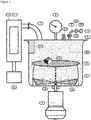
- Fig. 1 comprises a vacuum unit as chamber (1). This device uses vacuum for vaporizing the solvent or solvent mixture to be applied to elements and comprises a vacuum unit 1 as shown in Figure 1 with
- microwaves or ultrasonic waves are applied to the chamber by a microwave unit or a ultrasound unit, respectively.
- the microwave or ultrasound unit can be applied internally or externally. It is preferred that microwaves and/or ultrasonic waves are applied from outside to the chamber.
- the amount and wave length of the microwaves and/or ultrasonic waves can be adapted as is known to the skilled person such that solvent in the chamber is vaporized. Vaporization with microwaves and/or ultrasonic waves can be carried out at any convenient temperature, such as ambient temperature, and at any convenient pressure, such as ambient pressure, as long as the solvent is vaporized. It is also possible to use negative or positive pressure.
- the solvent/air mixture is withdrawn from the chamber and can be passed to a recovery unit which comprises at least one filter unit and/or a recovery trap.
- a recovery unit which comprises at least one filter unit and/or a recovery trap.
- solvent is adsorbed by the at least one filter unit and/or is condensed in a recovery trap.
- the recovered solvent can then be used again for the method of the present invention. Therefore, the use of a recovery unit contributes to an efficient and environmentally friendly process.
- activated carbon is useful as filter means as it is abundantly available and is active in absorbing the solvent or solvent mixture used for the process of the present invention efficiently and also efficiently desorbs the solvent.
- the number of cycles or runs for the filter unit before exchange and the number of units used in a specific process can be determined easily by a person skilled in the art.
- the solvent can be regenerated by desorption from the filter unit.
- the filter unit for example an activated carbon unit, can be heated to desorb the solvent.
- an air stream having a temperature beyond the boiling temperature of the solvent is passed through the filter unit. Thereafter, the air stream enriched with desorbed solvent is passed to a unit for recovery of the solvent by condensation.
- any trap that is known from distillation processes can be used.
- a cold trap such as a metal tube or a glass vessel can be used.
- the metal tube can be a tube made from any metal that is inert with regard to the solvent, such as copper or aluminum or any other metal or alloy.
- the tube can be straight, bent, curved, crooked, or can be in the form of a spiral.
- the tube can be cooled by a heat exchange unit and/or a fluid bath or any other known means.
- HFIP or a solvent mixture can be condensed and drops into a collecting vessel, such as a collecting jar or a collecting bottle.
- HFIP has a relatively high density (1.6 kg/L) which provides for fast running down of the condensed solvent.
- the air, separated from HFIP vapor having a high temperature, can be passed again into the filtration unit to start a new desorption/condensing cycle.
- the device of the present invention can be used to treat elements with solvent vapor.
- the solvent to be vaporized can be a solvent or a mixture of solvents, such as one or more halogen containing solvents like HFIP, organic solvents like acetone or other solvents that preferably have a boiling point in the range of about 40°C to about 100°C, or mixtures of these solvents.
- a solvent is HFIP or a mixture comprising HFIP.
- HFIP is mentioned, but any other solvent could be used instead as long as the boiling point is in a suitable range.
- the element to be treated can be any element that should be treated with a vapor or a solvent in gaseous form, respectively.
- An example for an element to be treated is an element obtained by an additive manufacturing process, in particular an element as described above.
- the device comprises a chamber for treating an element with a solvent in gaseous form, wherein a solvent is vaporized and is in contact with at least one element and wherein the solvent is recovered by a recovery means, such as a filter unit or a cold trap.
- a recovery means such as a filter unit or a cold trap.
- the air/solvent mixture is withdrawn from the chamber and solvent is recovered by passing it through a filter unit with at least one filter element.
- the filter element can be made of any material that is used for solvent recovery such as activated carbon.
- the filter material can be in the form of a membrane, a powder, particles, granules or any other form known to the skilled person. It is also possible to recover solvent by using known solvent recovery means such as cold traps.
- FIG. 1 shows an embodiment of the device for treatment of elements of the present invention.
- the vacuum device comprises a vacuum unit 1 with a lid 2 for closing the vacuum unit. Elements 6 to be treated are positioned on element contact area 5.
- Solvent 14 to be used for treatment of the surface of elements 6 is introduced into the vacuum unit 1 from solvent container 13 via solvent feed line 9.
- Solvent 14 is introduced into the vacuum unit 1 by a feed pump 16 and introduction is controlled via stop valve 15.
- At least one fan propeller 4 can be provided which is driven by an engine 3 connected to the fan propeller 4 via a vacuum-tight rotary transmission 18.
- vacuum unit 1 is evaporated by a vacuum pump 12 via vacuum tube 7. After evaporation the vacuum unit 1 comprises a solvent/air mixture 20.
- the pressure inside the vacuum unit is monitored by a pressure gauge 8. Element(s) 6 are in contact with the solvent vapor for a predetermined time period. Thereafter, pressure is released via venting valve 19 and solvent is removed via vacuum tube 7.
- the solvent/air mixture 20 is withdrawn from the vacuum unit 1 by vacuum pump 12 and is passed through at least one filter 10 comprising activated carbon 11. By passing through the filter the solvent is absorbed by activated carbon and can be recovered and reused.
- the method of the present invention provides for elements with smooth surface that can be used for many purposes.
- the elements obtained with the method of the present invention are particularly useful for in the medicinal and food industry.
- smooth surfaces are important not only for esthetical reasons but also for hygienic reasons.
- the treatment is carried out with a solvent that does not change the elements chemically so that no toxic side products are created.
- elements obtained by additive manufacturing using powder as building material or that have been treated by mechanical grinding or milling have powder on the surface that could be contaminating, i.e. could be taken up by the body when it is on a medicinal product that is inserted in the body or could be taken up by food that is in contact with such an element. This is avoided when using the treatment of the present invention where any powder remaining on the surface after the manufacturing process is "melted in” by treatment with the solvent.
- the elements obtained by the method of the present invention are particularly useful for medicinal and food processing devices.
- a vacuum device as shown in Figure 1 was used to treat polyamide elements: (having a grey color) obtained by an MJF process.
- Elements 6 were laid on an element contact area 5 of vacuum unit 1 and the unit was closed with vacuum lid 2.
- Engine 3 driving fan propeller 4 was switched on to provide for circulation of air.
- vacuum pump 12 was switched on and air was withdrawn until pressure gauge 8 showed a pressure of 0.1 bar (absolute).
- vacuum pump 12 was switched off. 5 ml of HFIP as solvent 14 were injected into vacuum chamber 1 via solvent feed line 9. The solvent vaporized and the HFIP vapor was circulated in the vacuum chamber for 10 minutes.
- the vacuum unit was neither cooled nor heated.
- a vacuum device as shown in Figure 1 was used to treat polyamide elements: obtained by an SLS process.
- Elements 6 were laid on an element contact area 5 of vacuum unit 1 and the unit was closed with vacuum lid 2.
- Engine 3 driving fan propeller 4 was switched on to provide for circulation of air.
- vacuum pump 12 was switched on and air was withdrawn until pressure gauge 8 showed a pressure of 0.1 bar (absolute).
- vacuum pump 12 was switched off.
- 5 ml of HFIP as solvent 14 were injected into vacuum chamber 1 via solvent feed line 9. The solvent vaporized and the HFIP vapor was circulated in the vacuum chamber for 15 minutes.
- the vacuum unit was neither cooled nor heated.
Landscapes
- Physics & Mathematics (AREA)
- Chemical & Material Sciences (AREA)
- Engineering & Computer Science (AREA)
- Manufacturing & Machinery (AREA)
- Materials Engineering (AREA)
- Mechanical Engineering (AREA)
- Optics & Photonics (AREA)
- Application Of Or Painting With Fluid Materials (AREA)
Priority Applications (10)
| Application Number | Priority Date | Filing Date | Title |
|---|---|---|---|
| EP18181048.2A EP3587092A1 (fr) | 2018-06-30 | 2018-06-30 | Procédé de traitement d'éléments obtenus par un processus de fabrication additive |
| PCT/EP2019/059819 WO2019201932A1 (fr) | 2018-04-16 | 2019-04-16 | Procédé de traitement d'éléments obtenus par un procédé de fabrication additive |
| CA3097433A CA3097433A1 (fr) | 2018-04-16 | 2019-04-16 | Procede de traitement d'elements obtenus par un procede de fabrication additive |
| EP19716948.5A EP3781389A1 (fr) | 2018-04-16 | 2019-04-16 | Procédé de traitement d'éléments obtenus par un procédé de fabrication additive |
| US17/047,839 US20210170702A1 (en) | 2018-04-16 | 2019-04-16 | Method for treatment of elements obtained by an additive manufacturing process |
| US17/047,841 US20210114304A1 (en) | 2018-04-16 | 2019-04-16 | Method for treatment of elements obtained by an additive manufacturing process |
| PCT/EP2019/059808 WO2019201922A1 (fr) | 2018-04-16 | 2019-04-16 | Procédé de traitement d'éléments obtenus par un procédé de fabrication additive |
| EP19716942.8A EP3781388A1 (fr) | 2018-04-16 | 2019-04-16 | Procédé de traitement d'éléments obtenus par un procédé de fabrication additive |
| CA3097420A CA3097420A1 (fr) | 2018-04-16 | 2019-04-16 | Procede de traitement d'elements obtenus par un procede de fabrication additive |
| US17/875,023 US12454107B2 (en) | 2018-04-16 | 2022-07-27 | Method for treatment of elements obtained by an additive manufacturing process |
Applications Claiming Priority (1)
| Application Number | Priority Date | Filing Date | Title |
|---|---|---|---|
| EP18181048.2A EP3587092A1 (fr) | 2018-06-30 | 2018-06-30 | Procédé de traitement d'éléments obtenus par un processus de fabrication additive |
Publications (1)
| Publication Number | Publication Date |
|---|---|
| EP3587092A1 true EP3587092A1 (fr) | 2020-01-01 |
Family
ID=62841893
Family Applications (1)
| Application Number | Title | Priority Date | Filing Date |
|---|---|---|---|
| EP18181048.2A Withdrawn EP3587092A1 (fr) | 2018-04-16 | 2018-06-30 | Procédé de traitement d'éléments obtenus par un processus de fabrication additive |
Country Status (1)
| Country | Link |
|---|---|
| EP (1) | EP3587092A1 (fr) |
Cited By (7)
| Publication number | Priority date | Publication date | Assignee | Title |
|---|---|---|---|---|
| FR3096370A1 (fr) * | 2019-05-24 | 2020-11-27 | Commissariat A L'energie Atomique Et Aux Energies Alternatives | Procédé de traitement d’une pièce polymère en vue de modifier sa rugosité et/ou de la fonctionnaliser |
| WO2021180648A1 (fr) * | 2020-03-09 | 2021-09-16 | Dyemansion Gmbh | Dispositif et procédé de traitement de surface de pièces moulées |
| GB2603898A (en) * | 2021-02-12 | 2022-08-24 | Additive Manufacturing Tech Ltd | Method of colouring additively manufactured parts |
| WO2022211775A1 (fr) * | 2021-03-29 | 2022-10-06 | Hewlett-Packard Development Company, L.P. | Fabrication d'objets imprimés en 3d |
| GB2611314A (en) * | 2021-09-29 | 2023-04-05 | Additive Manufacturing Tech Ltd | Additive manufacturing method and apparatus |
| EP4241991A1 (fr) * | 2022-03-10 | 2023-09-13 | Howmedica Osteonics Corporation | Procédé de coloration ou de traitement en surface de pièces en polymère |
| PL450920A1 (pl) * | 2025-01-08 | 2026-03-02 | Politechnika Poznańska | Urządzenie do wygładzania selektywnego powierzchni rolek wytworzonych w technologii druku 3D |
Citations (6)
| Publication number | Priority date | Publication date | Assignee | Title |
|---|---|---|---|---|
| US5248456A (en) * | 1989-06-12 | 1993-09-28 | 3D Systems, Inc. | Method and apparatus for cleaning stereolithographically produced objects |
| US20050220983A1 (en) * | 2002-05-13 | 2005-10-06 | Jonathan Hayes | Method of processing a stack of coatings and apparatus for processing a stack of coatings |
| US8075300B2 (en) * | 2008-06-30 | 2011-12-13 | Stratasys, Inc. | Vapor smoothing surface finishing system |
| DE102014102137A1 (de) | 2014-02-19 | 2015-08-20 | Dyemansion Gmbh | Verfahren zum Behandeln von Oberflächen von Kunststoffgegenständen |
| US20170327658A1 (en) | 2016-05-10 | 2017-11-16 | Sculpteo | Surface treatment process for objects |
| WO2018111548A1 (fr) * | 2016-12-14 | 2018-06-21 | Carbon, Inc. | Procédés et appareil pour laver des objets produits par stéréolithographie |
-
2018
- 2018-06-30 EP EP18181048.2A patent/EP3587092A1/fr not_active Withdrawn
Patent Citations (6)
| Publication number | Priority date | Publication date | Assignee | Title |
|---|---|---|---|---|
| US5248456A (en) * | 1989-06-12 | 1993-09-28 | 3D Systems, Inc. | Method and apparatus for cleaning stereolithographically produced objects |
| US20050220983A1 (en) * | 2002-05-13 | 2005-10-06 | Jonathan Hayes | Method of processing a stack of coatings and apparatus for processing a stack of coatings |
| US8075300B2 (en) * | 2008-06-30 | 2011-12-13 | Stratasys, Inc. | Vapor smoothing surface finishing system |
| DE102014102137A1 (de) | 2014-02-19 | 2015-08-20 | Dyemansion Gmbh | Verfahren zum Behandeln von Oberflächen von Kunststoffgegenständen |
| US20170327658A1 (en) | 2016-05-10 | 2017-11-16 | Sculpteo | Surface treatment process for objects |
| WO2018111548A1 (fr) * | 2016-12-14 | 2018-06-21 | Carbon, Inc. | Procédés et appareil pour laver des objets produits par stéréolithographie |
Cited By (12)
| Publication number | Priority date | Publication date | Assignee | Title |
|---|---|---|---|---|
| FR3096370A1 (fr) * | 2019-05-24 | 2020-11-27 | Commissariat A L'energie Atomique Et Aux Energies Alternatives | Procédé de traitement d’une pièce polymère en vue de modifier sa rugosité et/ou de la fonctionnaliser |
| US12202949B2 (en) | 2019-05-24 | 2025-01-21 | Commissariat à l'énergie atomique et aux énergies alternatives | Method for treating a polymer part in order to modify its roughness and/or to functionalise it |
| WO2021180648A1 (fr) * | 2020-03-09 | 2021-09-16 | Dyemansion Gmbh | Dispositif et procédé de traitement de surface de pièces moulées |
| CN115551697A (zh) * | 2020-03-09 | 2022-12-30 | 戴漫森有限责任公司 | 用于处理成型件表面的装置及方法 |
| US12377621B2 (en) | 2020-03-09 | 2025-08-05 | Dyemansion Gmbh | Method for treating the surface of moulded parts |
| GB2603898A (en) * | 2021-02-12 | 2022-08-24 | Additive Manufacturing Tech Ltd | Method of colouring additively manufactured parts |
| WO2022211775A1 (fr) * | 2021-03-29 | 2022-10-06 | Hewlett-Packard Development Company, L.P. | Fabrication d'objets imprimés en 3d |
| EP4313556A4 (fr) * | 2021-03-29 | 2024-12-04 | Hewlett-Packard Development Company, L.P. | Fabrication d'objets imprimés en 3d |
| US12570048B2 (en) | 2021-03-29 | 2026-03-10 | Peridot Print Llc | Manufacturing 3D printed objects |
| GB2611314A (en) * | 2021-09-29 | 2023-04-05 | Additive Manufacturing Tech Ltd | Additive manufacturing method and apparatus |
| EP4241991A1 (fr) * | 2022-03-10 | 2023-09-13 | Howmedica Osteonics Corporation | Procédé de coloration ou de traitement en surface de pièces en polymère |
| PL450920A1 (pl) * | 2025-01-08 | 2026-03-02 | Politechnika Poznańska | Urządzenie do wygładzania selektywnego powierzchni rolek wytworzonych w technologii druku 3D |
Similar Documents
| Publication | Publication Date | Title |
|---|---|---|
| US12454107B2 (en) | Method for treatment of elements obtained by an additive manufacturing process | |
| US20210114304A1 (en) | Method for treatment of elements obtained by an additive manufacturing process | |
| US20220024125A1 (en) | Method for treatment of elements obtained by an additive manufacturing process | |
| JP6563380B2 (ja) | 付加製造した物体等への注入方法及び装置 | |
| EP2358517B1 (fr) | Fabrication d'un composant de composites structuraux | |
| US9314941B2 (en) | Aggregate-based mandrels for composite part production and composite part production methods | |
| US8715408B2 (en) | Aggregate-based mandrels for composite part production and composite part production methods | |
| CN102481731B (zh) | 制造先进复合材料部件的方法 | |
| DE102019113200A1 (de) | Vorrichtung zur Oberflächenbehandlung von in einem 3D-Druckverfahren hergestellten Formteil aus Kunststoff | |
| WO1986000033A1 (fr) | Procede et installation de fabrication de noyaux | |
| CA2770467C (fr) | Procede permettant de prolonger la fenetre de traitement des resines thermodurcissables | |
| CA3119537C (fr) | Procede de traitement d'elements obtenus par un procede de fabrication additive | |
| TW201609359A (zh) | 用於浸漬積層製造物體及其類似物之方法與裝置 | |
| JPH04115931A (ja) | 繊維強化フェノール樹脂成形体の引抜成形方法 | |
| KR101648741B1 (ko) | 다공질 필름 제조용 함침 코터 및 이를 구비한 함침 코팅 시스템 | |
| JPH02258676A (ja) | 炭素/炭素複合材料の製造法 |
Legal Events
| Date | Code | Title | Description |
|---|---|---|---|
| PUAI | Public reference made under article 153(3) epc to a published international application that has entered the european phase |
Free format text: ORIGINAL CODE: 0009012 |
|
| AK | Designated contracting states |
Kind code of ref document: A1 Designated state(s): AL AT BE BG CH CY CZ DE DK EE ES FI FR GB GR HR HU IE IS IT LI LT LU LV MC MK MT NL NO PL PT RO RS SE SI SK SM TR |
|
| AX | Request for extension of the european patent |
Extension state: BA ME |
|
| STAA | Information on the status of an ep patent application or granted ep patent |
Free format text: STATUS: THE APPLICATION HAS BEEN WITHDRAWN |
|
| 18W | Application withdrawn |
Effective date: 20200507 |