EP3587200A1 - Bremssystem für ein flugzeug mit dualem fahrwerk - Google Patents
Bremssystem für ein flugzeug mit dualem fahrwerk Download PDFInfo
- Publication number
- EP3587200A1 EP3587200A1 EP19182722.9A EP19182722A EP3587200A1 EP 3587200 A1 EP3587200 A1 EP 3587200A1 EP 19182722 A EP19182722 A EP 19182722A EP 3587200 A1 EP3587200 A1 EP 3587200A1
- Authority
- EP
- European Patent Office
- Prior art keywords
- wheels
- outboard
- inboard
- brake
- braking
- Prior art date
- Legal status (The legal status is an assumption and is not a legal conclusion. Google has not performed a legal analysis and makes no representation as to the accuracy of the status listed.)
- Granted
Links
Images




Classifications
-
- B—PERFORMING OPERATIONS; TRANSPORTING
- B60—VEHICLES IN GENERAL
- B60T—VEHICLE BRAKE CONTROL SYSTEMS OR PARTS THEREOF; BRAKE CONTROL SYSTEMS OR PARTS THEREOF, IN GENERAL; ARRANGEMENT OF BRAKING ELEMENTS ON VEHICLES IN GENERAL; PORTABLE DEVICES FOR PREVENTING UNWANTED MOVEMENT OF VEHICLES; VEHICLE MODIFICATIONS TO FACILITATE COOLING OF BRAKES
- B60T8/00—Arrangements for adjusting wheel-braking force to meet varying vehicular or ground-surface conditions, e.g. limiting or varying distribution of braking force
- B60T8/17—Using electrical or electronic regulation means to control braking
- B60T8/1701—Braking or traction control means specially adapted for particular types of vehicles
- B60T8/1703—Braking or traction control means specially adapted for particular types of vehicles for aircrafts
-
- B—PERFORMING OPERATIONS; TRANSPORTING
- B64—AIRCRAFT; AVIATION; COSMONAUTICS
- B64C—AEROPLANES; HELICOPTERS
- B64C25/00—Alighting gear
- B64C25/32—Alighting gear characterised by elements which contact the ground or similar surface
- B64C25/42—Arrangement or adaptation of brakes
-
- B—PERFORMING OPERATIONS; TRANSPORTING
- B64—AIRCRAFT; AVIATION; COSMONAUTICS
- B64C—AEROPLANES; HELICOPTERS
- B64C25/00—Alighting gear
- B64C25/32—Alighting gear characterised by elements which contact the ground or similar surface
- B64C25/34—Alighting gear characterised by elements which contact the ground or similar surface wheeled type, e.g. multi-wheeled bogies
-
- F—MECHANICAL ENGINEERING; LIGHTING; HEATING; WEAPONS; BLASTING
- F15—FLUID-PRESSURE ACTUATORS; HYDRAULICS OR PNEUMATICS IN GENERAL
- F15B—SYSTEMS ACTING BY MEANS OF FLUIDS IN GENERAL; FLUID-PRESSURE ACTUATORS, e.g. SERVOMOTORS; DETAILS OF FLUID-PRESSURE SYSTEMS, NOT OTHERWISE PROVIDED FOR
- F15B13/00—Details of servomotor systems ; Valves for servomotor systems
- F15B13/02—Fluid distribution or supply devices characterised by their adaptation to the control of servomotors
- F15B13/028—Shuttle valves
-
- F—MECHANICAL ENGINEERING; LIGHTING; HEATING; WEAPONS; BLASTING
- F15—FLUID-PRESSURE ACTUATORS; HYDRAULICS OR PNEUMATICS IN GENERAL
- F15B—SYSTEMS ACTING BY MEANS OF FLUIDS IN GENERAL; FLUID-PRESSURE ACTUATORS, e.g. SERVOMOTORS; DETAILS OF FLUID-PRESSURE SYSTEMS, NOT OTHERWISE PROVIDED FOR
- F15B13/00—Details of servomotor systems ; Valves for servomotor systems
- F15B13/02—Fluid distribution or supply devices characterised by their adaptation to the control of servomotors
- F15B13/04—Fluid distribution or supply devices characterised by their adaptation to the control of servomotors for use with a single servomotor
- F15B13/0401—Valve members; Fluid interconnections therefor
-
- F—MECHANICAL ENGINEERING; LIGHTING; HEATING; WEAPONS; BLASTING
- F15—FLUID-PRESSURE ACTUATORS; HYDRAULICS OR PNEUMATICS IN GENERAL
- F15B—SYSTEMS ACTING BY MEANS OF FLUIDS IN GENERAL; FLUID-PRESSURE ACTUATORS, e.g. SERVOMOTORS; DETAILS OF FLUID-PRESSURE SYSTEMS, NOT OTHERWISE PROVIDED FOR
- F15B13/00—Details of servomotor systems ; Valves for servomotor systems
- F15B13/02—Fluid distribution or supply devices characterised by their adaptation to the control of servomotors
- F15B13/04—Fluid distribution or supply devices characterised by their adaptation to the control of servomotors for use with a single servomotor
- F15B13/042—Fluid distribution or supply devices characterised by their adaptation to the control of servomotors for use with a single servomotor operated by fluid pressure
-
- B—PERFORMING OPERATIONS; TRANSPORTING
- B60—VEHICLES IN GENERAL
- B60T—VEHICLE BRAKE CONTROL SYSTEMS OR PARTS THEREOF; BRAKE CONTROL SYSTEMS OR PARTS THEREOF, IN GENERAL; ARRANGEMENT OF BRAKING ELEMENTS ON VEHICLES IN GENERAL; PORTABLE DEVICES FOR PREVENTING UNWANTED MOVEMENT OF VEHICLES; VEHICLE MODIFICATIONS TO FACILITATE COOLING OF BRAKES
- B60T13/00—Transmitting braking action from initiating means to ultimate brake actuator with power assistance or drive; Brake systems incorporating such transmitting means, e.g. air-pressure brake systems
- B60T13/10—Transmitting braking action from initiating means to ultimate brake actuator with power assistance or drive; Brake systems incorporating such transmitting means, e.g. air-pressure brake systems with fluid assistance, drive, or release
- B60T13/12—Transmitting braking action from initiating means to ultimate brake actuator with power assistance or drive; Brake systems incorporating such transmitting means, e.g. air-pressure brake systems with fluid assistance, drive, or release the fluid being liquid
-
- B—PERFORMING OPERATIONS; TRANSPORTING
- B60—VEHICLES IN GENERAL
- B60T—VEHICLE BRAKE CONTROL SYSTEMS OR PARTS THEREOF; BRAKE CONTROL SYSTEMS OR PARTS THEREOF, IN GENERAL; ARRANGEMENT OF BRAKING ELEMENTS ON VEHICLES IN GENERAL; PORTABLE DEVICES FOR PREVENTING UNWANTED MOVEMENT OF VEHICLES; VEHICLE MODIFICATIONS TO FACILITATE COOLING OF BRAKES
- B60T2270/00—Further aspects of brake control systems not otherwise provided for
- B60T2270/40—Failsafe aspects of brake control systems
-
- F—MECHANICAL ENGINEERING; LIGHTING; HEATING; WEAPONS; BLASTING
- F15—FLUID-PRESSURE ACTUATORS; HYDRAULICS OR PNEUMATICS IN GENERAL
- F15B—SYSTEMS ACTING BY MEANS OF FLUIDS IN GENERAL; FLUID-PRESSURE ACTUATORS, e.g. SERVOMOTORS; DETAILS OF FLUID-PRESSURE SYSTEMS, NOT OTHERWISE PROVIDED FOR
- F15B2211/00—Circuits for servomotor systems
- F15B2211/30—Directional control
- F15B2211/305—Directional control characterised by the type of valves
- F15B2211/3052—Shuttle valves
-
- Y—GENERAL TAGGING OF NEW TECHNOLOGICAL DEVELOPMENTS; GENERAL TAGGING OF CROSS-SECTIONAL TECHNOLOGIES SPANNING OVER SEVERAL SECTIONS OF THE IPC; TECHNICAL SUBJECTS COVERED BY FORMER USPC CROSS-REFERENCE ART COLLECTIONS [XRACs] AND DIGESTS
- Y02—TECHNOLOGIES OR APPLICATIONS FOR MITIGATION OR ADAPTATION AGAINST CLIMATE CHANGE
- Y02T—CLIMATE CHANGE MITIGATION TECHNOLOGIES RELATED TO TRANSPORTATION
- Y02T50/00—Aeronautics or air transport
- Y02T50/80—Energy efficient operational measures, e.g. ground operations or mission management
Definitions
- the present disclosure generally relates to braking systems for aircraft, and more specifically, to a brake pairing scheme for dual landing gear aircraft that creates a straight-forward and robust braking system.
- Aircraft can include dual landing gear architectures that include multiple wheel sets.
- Each wheel set includes the wheels arranged in two or more inboard wheels and two or more outboard wheels.
- the wheels were further arranged in sets of fore wheels that are closer to the front of the aircraft and aft wheels towards the rear of the aircraft.
- the present application is directed to a braking system for an aircraft.
- the braking system is configured to provide for symmetrical braking of the wheels of the aircraft.
- the braking system includes an outboard brake system control unit with at least a first processing circuit that generates brake control signals to symmetrically control braking of a first wheel pair including just the outboard fore wheels and a second wheel pair including just the outboard aft wheels in response to pilot input.
- An inboard brake system control unit includes at least a second processing circuit that generates brake control signals to symmetrically control braking of a third wheel pair including just the inboard fore wheels and a fourth wheel pair including just the inboard aft wheels in response to the pilot input.
- the inboard brake system control unit is independent from the outboard brake system control unit.
- a hydraulic system applies braking forces to the wheels in response to the brake control signals.
- the outboard brake system control unit transmits the brake control signals along a first control lane to brake just the outboard fore wheels of both the left and right landing gears and transmits the brake control signals along a second control lane to brake just the outboard aft wheels of both the left and right landing gears with the first control lane being independent from the second control lane.
- the inboard brake system control unit transmits the brake control signals along a third control lane to brake just the inboard fore wheels of both the left and right landing gears and transmits the brake control signals along a fourth control lane to brake just the inboard aft wheels of both the left and right landing gears with the third control lane being independent from the fourth control lane.
- the inboard and outboard braking system control units further include input interfaces configured to receive the pilot input with the pilot input comprising separate first and second inputs.
- the hydraulic system includes first hydraulic lines and alternate lines that supply hydraulic fluid to brakes at the wheels, servo-valves positioned along the first hydraulic lines and the alternate lines to modulate the pressure of the hydraulic fluid supplied to the brakes in response to the brake control signals received from the first and second brake system control units, shuttle valves that operatively connect the first hydraulic lines and the alternate lines with the shuttle valves configured to supply hydraulic fluid from one of the first hydraulic lines and the alternate lines.
- each of the servo-valves positioned along the first hydraulic lines modulate pressure to one of the brakes and the servo-valves positioned along the alternate supply lines modulate pressure to a pair of the brakes on one of the left and right landing gears.
- a first module houses each of the servo-valves that modulate the pressure of the hydraulic fluid along the first hydraulic lines to the brakes of one of the left and right landing gears and a second module that houses each of the servo-valves that modulate the pressure of the hydraulic fluid along the first hydraulic lines to the brakes of the other of the left and right landing gears.
- each of the first and second modules include a shut-off valve to reduce leakage of the hydraulic fluid.
- the outboard brake system control unit controls the servo-valves that supply hydraulic fluid to each of the fore and aft outboard wheels and the inboard brake system control unit controls the servo-valves that supply hydraulic fluid to each of the fore and aft inboard wheels.
- One aspect is directed to an aircraft with a braking system that includes an outboard brake system control unit with at least a first processing circuit that generates brake control signals to symmetrically control braking of a first wheel pair including just the outboard fore wheels and a second wheel pair including just the outboard aft wheels in response to pilot input.
- the braking system includes an inboard brake system control unit includes at least a second processing circuit that generates brake control signals to symmetrically control braking of a third wheel pair including just the inboard fore wheels and a fourth wheel pair including just the inboard aft wheels in response to the pilot input.
- the inboard brake system control unit is independent from the outboard brake system control unit.
- the braking system includes a hydraulic system applies braking forces to the wheels in response to the brake control signals.
- the braking system includes a hydraulic system with a plurality of supply lines that each supply hydraulic fluid to control braking of one of the wheels. Each of the supply lines includes a plurality of valves, and a brake to apply a braking force to one of the wheels.
- the braking system includes an outboard brake system control unit with a first processing circuit that generates brake control signals to control the valves of a first wheel pair with just the outboard fore wheels and the valves of a second wheel pair with just the outboard aft wheels in response to pilot input.
- An inboard brake system control unit includes a second processing circuit that generates brake control signals to control the valves of a third wheel pair with just the inboard fore wheels and the valves of a fourth wheel pair with just the inboard aft wheels.
- the outboard and inboard brake system control units receive pilot input and control the valves of each of the wheel pairs to apply a symmetrical braking force to the wheels of each of the wheel pairs.
- a first control lane extends between the outboard brake system control unit and one of the valves on one of the supply lines of the outboard fore wheels
- a second control lane extends between the outboard brake system control unit and one of the valves on one of the supply lines of the outboard aft wheels
- a third control lane extends between the inboard brake system control unit and one of the valves on one of the supply lines of the inboard fore wheels
- a fourth control lane extends between the inboard brake system control unit and one of the valves on one of the supply lines of the inboard aft wheels with each of the control lanes being independent of each other.
- the hydraulic system includes a first hydraulic supply line and an alternate hydraulic supply line and each of the supply lines further include a shuttle valve to selectively deliver the hydraulic fluid to the brakes from one of the first hydraulic supply line and the alternate hydraulic supply line based on the pilot input.
- each of the inboard and outboard brake system control units receives the pilot input from both first and second pilots.
- One aspect is directed to a method of braking an aircraft.
- the method includes receiving pilot input at both an outboard brake system control unit and an inboard brake system control unit.
- the method includes based on the pilot input, sending first braking signals from the outboard brake system control unit and symmetrically braking a first pair of fore outboard wheels of a right landing gear and a left landing gear and a second pair of aft outboard wheels on the right landing gear and the left landing gear.
- the method includes based on the pilot input, sending second braking signals from the inboard brake system control unit and symmetrically braking a third pair of aft inboard wheels of the right landing gear and the left landing gear and a fourth pair of aft inboard wheels on the right landing gear and the left landing gear.
- the method includes sending the first braking signals to the first pair of fore outboard wheels from the outboard brake system control unit via a first control lane and sending the first braking signals from the outboard brake system control unit to the second pair of aft outboard wheels via an independent second control lane.
- the method includes sending the second braking signals to the third pair of fore inboard wheels from the inboard brake system control unit via a third control lane and sending the second braking signals from the inboard brake system control unit to the fourth pair of aft inboard wheels from the inboard brake system control unit via an independent fourth control lane.
- the method includes determining from the pilot input a greater of a first input and a second input and based on the greater of the first and second inputs sending the first braking signals from the outboard brake system control unit and symmetrically braking the first and second pairs of outboard wheels and based on the greater of the first and second inputs sending the second braking signals from the inboard brake system control unit and symmetrically braking the third and fourth pairs of inboard wheels.
- the method includes determining from the pilot input a lesser of the brake command between the forward and aft wheel pair and controlling alternate braking based on the lesser of the brake command between the forward and aft wheel pair.
- the method includes sending the braking signals to servo-valves and adjusting a flow of hydraulic fluid and adjusting the braking of the pairs of brakes.
- the present application is directed to a braking system for use with a dual landing gear aircraft.
- the braking system pairs outboard brake control into an outboard brake system control unit (BSCU) and inboard brake control into a second inboard brake system control unit (BSCU).
- BSCU outboard brake system control unit
- BSCU second inboard brake system control unit
- Each BSCU is designed with two independent control lanes in which the forward wheel set is paired in one control lane and the aft wheels are paired onto the other.
- Locked wheel and hydroplane protection is provided by communication between control lanes within a given BSCU.
- Alternate braking is provided via an alternate brake module installed in a fore-aft wheel pairing and is commanded via a shared controlled lane with each BSCU.
- the architecture optimally blends the preferred inboard/outboard architecture while maintaining control valves in close proximity to the brakes.
- Each BSCU receives braking control signals from pedals from first and second pilots.
- the BSCU logic is such that the greater of the first and second pilot commands is selected when applying the brakes at below the skid pressure of the tire. Above the skid pressure of the tire, the brake command is generated via an antiskid function. Alternate brake control commands are generated using the lesser of the brake commands between the forward and aft wheel pair.
- Figure 1 is a schematic representation of a braking system 10 for an aircraft having a pair of wheel groups 60.
- the braking system 10 includes an outboard BSCU 20 and an inboard BSCU 30.
- Each of the outboard and inboard BSCU 20, 30 receives inputs from brake pedals 65 from the pilots.
- the outboard and inboard BSCUs 20, 30 independently generate and apply brake actuator control signals to a hydraulic system 40 to independently control brakes on the wheels 69 of the wheel groups 60 of the aircraft.
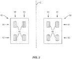
- the braking system 10 is configured for use with an aircraft having a landing gear with dual wheel groups 60 as illustrated in Figure 2 .
- the wheel groups 60 can be positioned on opposing sides (i.e., right and left sides) of a longitudinal centerline C of the aircraft. Additionally or alternatively, the wheel groups 60 can be positioned on the same side of the longitudinal centerline C.
- Each wheel group 60 is depicted in a two-dimensional array having a row 61 of two or more fore wheels 69 and a row 62 of two or more aft wheels 69.
- the wheel groups 60 are also aligned to include an inboard row 63 of two or more wheels 69 that are in closer proximity to the centerline C than an outboard row 64 that are farther from the centerline C.
- the wheel groups 60 can include a variety of arrangements, including but not limited to one or more rows of three of more wheels 69.
- FIG 3 illustrates a more detailed schematic representation of the braking system 10 within the context of an aircraft.
- the braking system 10 is positioned to receive signals from the pilot pedals 65 and control braking of the wheels 69 of the wheel groups 60.
- the outboard and inboard BSCUs 20, 30 receive inputs from the pilot brake pedals 65.
- pedal inputs from the first pilot brake pedals 65 are received by the outboard BSCU 20.
- Pedal inputs from the second pilot brake pedals 65 are received by the inboard BSCU 30.
- the BSCUs 20, 30 can receive different pedal inputs, such as each BSCU 20, 30 receiving one input from each pilot (e.g., BSCU 20 receives right pedal inputs from both pilots and BSCU 30 receives left pedal inputs from both pilots).
- each pilot is provided with two brake pedals 65, such as a left brake pedal 65 and a right brake pedal 65.
- the pilot pedals 65 can include a first pair of pedals 65 provided for a first pilot (e.g., captain) and a second pair of pedals 65 provided for a second pilot (e.g., first officer).
- the pilots physically manipulate the pedals 65 to generate a pilot pedal physical input.
- the physical input of the first and second pilot pedals 65 are measured from their natural positions by sensors or equivalent components, converted into first and second pilot command control signals by transducers or equivalent components. Signals from the first pilot brake pedals 65 are received at the outboard BSCU 20 and signals from the second pilot brake pedals 65 at the inboard BSCU 30.
- the inboard and outboard BSCUs 20, 30 are configured to receive the signals from the brake pedals 65, process the signals, and control valves in the hydraulic system 40.
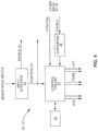
- Each of the inboard and outboard BSCUs 20, 30 can be the same and include the same components as illustrated in Figure 4 .
- Each of the inboard and outboard BSCUs 20, 30 includes a processing circuit 21 with one or more general-purpose and/or dedicated processors, including (but not limited to) one or more microprocessors, microcontrollers, application-specific integrated circuits (ASICs), field-programmable gate arrays (FPGAs), digital signal processors (DSPs), and/or other circuitry configured with appropriate software and/or firmware to control the various components according to program instructions stored in a memory circuit 22.
- the memory circuit 22 stores processing logic, programming code, and operational information for use by the processing circuit 21.
- the memory circuit 22 can include volatile memory, nonvolatile memory, or both, according to various embodiments.
- Each BSCU 20, 30 includes a shared control lane that has an independent enable circuit which provides power to the hydraulic enable solenoids to control shut-off valves 47 within the hydraulic braking system.
- the circuit can also control alternate brake command drivers that are isolated valve driver circuits that select the lesser of two normal system brake commands.
- An input interface 23 is configured to receive pilot inputs over a wired connection, such as a serial, USB, micro USB, FIREWIRE, Lightning, and/or Thunderbolt connection.
- the input interface 23 can also be configured to receive the pilot inputs via wireless radio, electrical, and/or optical signals.
- the input interface 23 can also receive signals from one or more other sources, such as a flight controller that oversees operations of the aircraft.
- Each BSCU 20, 30 can include a digital-to-analog converter 24 to convert the digital enable signal.
- each of the outboard and inboard BSCUs 20, 30 initially receives input signals from certain ones of the brake pedals 65.
- An analog signal based on the received digital signal is sent to the opposing BSCU 20, 30 indicating activation of the brake pedals 65.
- Digital position signals are also received indicating the position of the brake pedals 65 and extent that the pilots apply braking.
- each BSCU 20, 30 shares with the other the analog enable signal indicating activation of the brake pedals and a digital position signal indicating the extent to which the pedals have been activated by the pilots.
- each BSCU 20, 30 is able to analyze each of the brake signals.
- Each BSCU 20, 30 analyzes the inputs and selects the greater of the two pilot pedal inputs.
- the greater of the two pilot brake commands is selected to apply the brakes 50 using first brake modules 41 of the hydraulic system 40.
- the lesser of the two forward or aft brake commands is used for alternate braking using alternate brake modules 42.
- each BSCU 20, 30 includes two independent control lanes to control servo-valves 46 in the first brake modules 41.
- the outboard BSCU 20 includes a first control lane 91 that pairs the brakes 50 of the forward outboard pair of wheels 69a, 69b and a second control lane 92 that pairs the brakes 50 of the aft outboard wheels 69c, 69d.
- a first control lane 93 from the inboard BSCU 30 pairs the brakes 50 of the forward inboard wheels 69e, 69f
- a second control lane 94 pairs the brakes 50 of the aft inboard wheels 69g, 69h.
- Each BSCU 20, 30 also includes shared controlled lanes to control the alternate braking.
- BSCU 20 includes shared control lane 95 that leads to the alternate brake modules 42 and likewise BSCU 30 includes shared control lane 96 that leads to the alternate brake modules 42.
- Figure 5 illustrates brake command processing by each BSCU 20, 30.
- the brake pedal commands are received by the BSCUs 20, 30 that determine the greater of the two pilot braking signals (block 180).
- a brake pressure is determined based on the angle of pedal deployment (block 182).
- the brake pressure can be determined via a lookup table.
- the determined brake pressure is then compared with an autobrake pressure command (block 190) with the greater of the two being used to control the first brake modules 41 (block 184).
- the brake command is generated via a normal antiskid function.
- An anti-skid command (block 192) causes a release in brake pressure (block 186) to prevent the skid with the braking commands sent to control the first brake modules 41.
- the lesser of the fore and aft brake commands are sent to the shared channel.
- the shared channel also receives the lesser of the fore-aft brake commands from the other BSCU 20, 30 (block 194). These signals are sent through the alternate control lanes to control the alternate brake modules 42.
- the outboard BSCU 20 includes control lane 95 to the alternate brake modules 42 to control a servo-valve 46 that controls the brakes 50 of the outboard wheels 69a, 69c of the first wheel group 60, and a servo-valve 46 that controls the brakes 50 of the outboard wheels 69b, 69d of the second wheel group 60.
- the inboard BSCU 30 includes a control lane 96 for servo-valves 46 that control the brakes of the inboard wheels 69e, 69g of the first wheel set 60 and brakes 50 of the inboard wheels 69f, 69h of the second wheel set 60.
- the wheels set 60 of each landing gear share a first brake module 41.
- the single first brake module 41 includes servo-valves 46 that control braking on each of the wheels of the wheel group 60.
- the hydraulic system 40 as illustrated in Figures 3 and 6 includes the first brake modules 41 and alternate brake modules 42.
- the first brake modules 41 are supplied by hydraulic fluid through one or more first lines 43.
- the alternate brake modules 42 are supplied by hydraulic fluid through one or more second lines 70.
- These lines 43, 70 can include separate hydraulic fluid supplies to provide a redundant system in the event of a failure in one section of the hydraulic system 40. Hydraulic fluid can be supplied to the brakes 50 through the non-failing supply to ensure braking of the wheels 69.
- Line 43 provides hydraulic fluid to the first brake modules 41 and line 70 provides hydraulic fluid to the alternate brake modules 42.
- Feed lines 49 extend from the first brake modules 41 to shuttle valve modules.
- Feed lines 75 extend from the alternate brake modules 42 to the shuttle valve modules 80.
- Feed lines 82 extend from the shuttle valve modules 80 to the brakes 50 of each of the wheels 69.
- the first brake modules 41 each include an outboard section 44 and an inboard section 45.
- the outboard section 44 includes a servo-valve 46 associated with the brakes 50 of each outboard wheel 69 of a wheel group 60.
- the inboard section 45 includes a servo-valve 46 associated with the brakes 50 of each inboard wheel 69 of the wheel group 60.
- the servo-valves 46 of the outboard section 44 are controlled by the outboard BSCU 20, and the servo-valves 46 of the inboard section 45 are controlled by the inboard BSCU 30.
- Fuses 48 are located along the lines 49 to prevent the depletion of a hydraulic system for a downstream leak.
- Each of the outboard section 44 and the inboard section 45 include a shut-off valve 47 to reduce leakage of hydraulic fluid.
- the shut-off valves 47 can also prevent single thread failures from inadvertently braking the wheels 69.
- the alternate brake modules 42 include pairs of servo-valves 46.
- a first servo-valve 46 is associated with a first line 75 through which hydraulic fluid is supplied to the pair of outboard brakes 50, and a second servo-valve 46 is associated with a second line 75 that supplies hydraulic fluid to the inboard brakes 50.
- the alternate brake modules 42 include a single servo-valve 46 for two brakes 50.
- the servo-valve 46 associated with the outboard brakes 50 is controlled by the outboard BSCU 20 and the servo-valve 46 associated with the inboard brakes 50 is controlled by the inboard BSCU 30.
- Fuses 48 are positioned along each of the lines 75 to prevent depletion of a hydraulic system for a downstream leak.
- the alternate brake modules 42 can include shut-off valves 47 to prevent the flow of hydraulic fluid as illustrated in Figure 3 .
- the shuttle valve modules 80 include a shuttle valve 81 associated with each of the brakes 50.
- Each shuttle valve 81 joins the hydraulic line 49 from the first brake module 41 and line 75 from the alternate brake module 42.
- Each of the shuttle valves 81 allow for hydraulic fluid to flow through it from one of these lines 49, 75 and into line 82 to control the associated brake 50.
- Hydraulic pressure sensors 89 that detect the fluid pressure can be positioned at various locations along the hydraulic system 40. This can include a pressure sensor 89 positioned along each of the lines 82 as illustrated in Figure 5 .
- the hydraulic system 40 includes sets of supply lines that each supply hydraulic fluid to control braking of one of the wheels 69.
- Each set includes lines 49, 75, 82, and one or more of valves 46, 47, 81.
- Each set also includes a brake 50 to apply a braking force to one of the wheels 69.
- the outboard BSCU 20 generates brake control signals in response to pilot input to control two sets of lines that include the valves 46, 47, 81 of a first wheel pair of just the outboard fore wheels 69 and two sets of lines that include the valves 46, 47, 81 of a second wheel pair of just the outboard aft wheels 69.
- the inboard BSCU 30 generates brake control signals in response to pilot input to control two sets of lines that include the valves 46, 47, 81 of a third wheel pair of just the inboard fore wheels 69 and two sets of lines that include the valves 46, 47, 81 of a fourth wheel pair of just the inboard aft wheels 69.
- the braking system 10 is configured to receive brake inputs from the pilots and apply a corresponding braking force.
- Figure 7 illustrates a method of braking an aircraft. Initially, brake inputs are received from the brake pedals 65 (block 200). This can include inputs from two or more pilots. Further, this can include one or more inputs from each of the pilots. In the embodiment of Figure 3 , the brake inputs include a pair of inputs from each of two pilots.
- the braking inputs are received from the pilots at the BSCUs 20, 30.
- the BSCUs 20, 30 calculate which pilot input is greater (block 202). This can include each BSCU 20, 30 calculating the extent of each pilot input based on different pedal input. In Figure 3 , this includes the outboard BSCU 20 determining the extent of the inputs based on a first set of pedal inputs from each pilot and the outboard BSCU 30 determining the extent of inputs based on a second set of pilot inputs.
- the BSCUs 20, 30 can share their calculations and each determines the greatest input. The determination of the extent of pilot input can also be calculated in other manners.
- the BSCUs 20, 30 use the greater pilot input to control the first brake modules 41 and control braking (block 204). For example, if the captain inputs are greater than the first officer, the pilot inputs will be used to control braking using the first brake modules 41.
- the lesser of the brake command between the fore and aft wheel pair are used for alternate braking (block 206).
- the braking system described above also provides for braking of the aircraft in the event of failure of one of the BSCUs 20, 30. In this event, the operational BSCU 20, 30 is able to control braking to stop the aircraft.
- the braking system 10 can be used in a variety of different aircraft.
- One aircraft includes a commercial aircraft that includes rows of seats each configured to accommodate a passenger.
- Other aircraft include but are not limited to manned aircraft, unmanned aircraft, manned spacecraft, unmanned spacecraft, manned rotorcraft, unmanned rotorcraft, satellites, rockets, missiles, manned terrestrial vehicles, unmanned terrestrial vehicles, and combinations thereof.
Landscapes
- Engineering & Computer Science (AREA)
- Mechanical Engineering (AREA)
- Aviation & Aerospace Engineering (AREA)
- Physics & Mathematics (AREA)
- Fluid Mechanics (AREA)
- General Engineering & Computer Science (AREA)
- Transportation (AREA)
- Regulating Braking Force (AREA)
- Valves And Accessory Devices For Braking Systems (AREA)
Applications Claiming Priority (1)
| Application Number | Priority Date | Filing Date | Title |
|---|---|---|---|
| US16/019,729 US10829210B2 (en) | 2018-06-27 | 2018-06-27 | Braking system for a dual landing gear aircraft |
Publications (2)
| Publication Number | Publication Date |
|---|---|
| EP3587200A1 true EP3587200A1 (de) | 2020-01-01 |
| EP3587200B1 EP3587200B1 (de) | 2020-06-10 |
Family
ID=67107355
Family Applications (1)
| Application Number | Title | Priority Date | Filing Date |
|---|---|---|---|
| EP19182722.9A Active EP3587200B1 (de) | 2018-06-27 | 2019-06-26 | Bremssystem für ein flugzeug mit dualem fahrwerk |
Country Status (5)
| Country | Link |
|---|---|
| US (1) | US10829210B2 (de) |
| EP (1) | EP3587200B1 (de) |
| JP (1) | JP7325244B2 (de) |
| CN (1) | CN110641687B (de) |
| RU (1) | RU2019119709A (de) |
Families Citing this family (3)
| Publication number | Priority date | Publication date | Assignee | Title |
|---|---|---|---|---|
| US11505167B2 (en) | 2020-01-06 | 2022-11-22 | The Boeing Company | Aircraft brake control systems |
| GB2602157A (en) * | 2020-12-21 | 2022-06-22 | Airbus Operations Ltd | Braking system |
| US12330619B2 (en) * | 2022-06-29 | 2025-06-17 | Goodrich Corporation | Alternate-secondary system in pressure control mode for minimal braking disruption in a primary-alternate braking system |
Citations (5)
| Publication number | Priority date | Publication date | Assignee | Title |
|---|---|---|---|---|
| FR2500798A1 (fr) * | 1981-01-28 | 1982-09-03 | Messier Hispano Sa | Dispositif de commande de freinage d'un aeronef |
| EP1547918A1 (de) * | 2003-12-22 | 2005-06-29 | Messier-Bugatti | Doppelt redundante Bremssystemarchitektur mit zwei Rechnern und zugehöriges Verfahren |
| EP2772428A1 (de) * | 2013-02-28 | 2014-09-03 | The Boeing Company | Kühlsystem eines Flugzeugfahrwerks |
| EP2871104A1 (de) * | 2013-11-07 | 2015-05-13 | Goodrich Corporation | System und Verfahren zur Aktivierung eines unabhängigen Bremssystems |
| EP3279045A1 (de) * | 2016-07-27 | 2018-02-07 | Goodrich Corporation | Systeme und verfahren zur bremsensteuerung |
Family Cites Families (13)
| Publication number | Priority date | Publication date | Assignee | Title |
|---|---|---|---|---|
| JP3851779B2 (ja) | 1999-05-14 | 2006-11-29 | ハイドロ エアー インコーポレイテッド | 二重冗長能動/能動ブレーキ・バイ・ワイヤ技術 |
| FR2816583B1 (fr) * | 2000-11-10 | 2003-02-21 | Messier Bugatti | Architecture de systeme hydraulique de freinage d'aeronef |
| US20050247529A1 (en) * | 2004-05-07 | 2005-11-10 | Gaines Louie T | Aircraft brake acuation system including an internally threaded ballscrew actuator assembly |
| US7317981B2 (en) * | 2004-11-19 | 2008-01-08 | Honeywell International, Inc. | Aircraft brake actuation system and method including anti-hysteresis control |
| GB2439742A (en) * | 2006-07-05 | 2008-01-09 | Dunlop Aerospace Ltd | Symmetrical braking control system in aircraft |
| US9656641B2 (en) * | 2006-08-04 | 2017-05-23 | The Boeing Company | Aircraft electrical brake control system architecture |
| US9108602B2 (en) | 2006-12-05 | 2015-08-18 | The Boeing Company | Parking brake control for an aircraft having an electric brake system |
| FR2952010B1 (fr) | 2009-10-30 | 2011-11-25 | Messier Bugatti | Architecture d'alimentation de freins d'aeronef equipes d'actionneurs electromecaniques |
| US9440735B2 (en) * | 2010-01-25 | 2016-09-13 | Honeywell International Inc. | Aircraft electric brake actuation system and method |
| US9950699B2 (en) | 2013-09-26 | 2018-04-24 | The Boeing Company | Brake load alleviation functions |
| US9463873B2 (en) | 2014-07-13 | 2016-10-11 | The Boeing Company | Vehicle braking system having braking control and skid reduction functions |
| US10450056B2 (en) | 2016-07-19 | 2019-10-22 | The Boeing Company | Horizontal stabilizer trim actuator systems and methods |
| CN107719651B (zh) * | 2017-09-13 | 2020-12-04 | 西安航空制动科技有限公司 | 飞机电刹车机电驱动架构及刹车力控制方法 |
-
2018
- 2018-06-27 US US16/019,729 patent/US10829210B2/en active Active
-
2019
- 2019-06-25 RU RU2019119709A patent/RU2019119709A/ru unknown
- 2019-06-25 JP JP2019116985A patent/JP7325244B2/ja active Active
- 2019-06-26 EP EP19182722.9A patent/EP3587200B1/de active Active
- 2019-06-27 CN CN201910565731.3A patent/CN110641687B/zh active Active
Patent Citations (5)
| Publication number | Priority date | Publication date | Assignee | Title |
|---|---|---|---|---|
| FR2500798A1 (fr) * | 1981-01-28 | 1982-09-03 | Messier Hispano Sa | Dispositif de commande de freinage d'un aeronef |
| EP1547918A1 (de) * | 2003-12-22 | 2005-06-29 | Messier-Bugatti | Doppelt redundante Bremssystemarchitektur mit zwei Rechnern und zugehöriges Verfahren |
| EP2772428A1 (de) * | 2013-02-28 | 2014-09-03 | The Boeing Company | Kühlsystem eines Flugzeugfahrwerks |
| EP2871104A1 (de) * | 2013-11-07 | 2015-05-13 | Goodrich Corporation | System und Verfahren zur Aktivierung eines unabhängigen Bremssystems |
| EP3279045A1 (de) * | 2016-07-27 | 2018-02-07 | Goodrich Corporation | Systeme und verfahren zur bremsensteuerung |
Also Published As
| Publication number | Publication date |
|---|---|
| BR102019013236A2 (pt) | 2020-01-14 |
| US20200001984A1 (en) | 2020-01-02 |
| CN110641687B (zh) | 2025-01-28 |
| RU2019119709A (ru) | 2020-12-25 |
| CN110641687A (zh) | 2020-01-03 |
| US10829210B2 (en) | 2020-11-10 |
| JP7325244B2 (ja) | 2023-08-14 |
| JP2020023308A (ja) | 2020-02-13 |
| EP3587200B1 (de) | 2020-06-10 |
Similar Documents
| Publication | Publication Date | Title |
|---|---|---|
| EP2109558B1 (de) | Selbstbremsende sperre für ein elektrisches flugzeug-bremssystem | |
| EP2097300B1 (de) | Elektrisches Bremssystem für ein Flugzeug | |
| EP3587200B1 (de) | Bremssystem für ein flugzeug mit dualem fahrwerk | |
| US7766431B2 (en) | System and method for an autobrake function for an aircraft electric brake system | |
| EP4001104B1 (de) | Flugzeugfahrwerklängskraftsteuerung | |
| US20190176966A1 (en) | Ground spoiler control architecture for aircraft | |
| EP3363697B1 (de) | Gleitschutzbetrieb im herabgestuften betrieb | |
| EP2091796A2 (de) | Bremssperre für ein elektrisches bremssystems eines flugzeugs | |
| GB2444630A (en) | Brake Status Indicator for an Electric Braking System of a Vehicle. | |
| EP3348474B1 (de) | System und verfahren zum automatischen bremsen mit kursverlaufsanpassung | |
| US10710561B2 (en) | Deceleration pedal control for braking systems | |
| BR102019013236B1 (pt) | Sistema de frenagem para uma aeronave com engrenagem de aterragem dual, aeronave e método de frenagem de uma aeronave | |
| EP4242076B1 (de) | Bremssteuerungsverfahren und bremssteuervorrichtung für ein fahrzeug, wie ein flugzeug | |
| US20240246663A1 (en) | System for controlling aircraft ground manoeuvres |
Legal Events
| Date | Code | Title | Description |
|---|---|---|---|
| PUAI | Public reference made under article 153(3) epc to a published international application that has entered the european phase |
Free format text: ORIGINAL CODE: 0009012 |
|
| STAA | Information on the status of an ep patent application or granted ep patent |
Free format text: STATUS: REQUEST FOR EXAMINATION WAS MADE |
|
| STAA | Information on the status of an ep patent application or granted ep patent |
Free format text: STATUS: EXAMINATION IS IN PROGRESS |
|
| 17P | Request for examination filed |
Effective date: 20190626 |
|
| AK | Designated contracting states |
Kind code of ref document: A1 Designated state(s): AL AT BE BG CH CY CZ DE DK EE ES FI FR GB GR HR HU IE IS IT LI LT LU LV MC MK MT NL NO PL PT RO RS SE SI SK SM TR |
|
| AX | Request for extension of the european patent |
Extension state: BA ME |
|
| 17Q | First examination report despatched |
Effective date: 20191213 |
|
| GRAP | Despatch of communication of intention to grant a patent |
Free format text: ORIGINAL CODE: EPIDOSNIGR1 |
|
| STAA | Information on the status of an ep patent application or granted ep patent |
Free format text: STATUS: GRANT OF PATENT IS INTENDED |
|
| RIC1 | Information provided on ipc code assigned before grant |
Ipc: B60T 8/17 20060101AFI20200326BHEP |
|
| GRAS | Grant fee paid |
Free format text: ORIGINAL CODE: EPIDOSNIGR3 |
|
| INTG | Intention to grant announced |
Effective date: 20200409 |
|
| GRAA | (expected) grant |
Free format text: ORIGINAL CODE: 0009210 |
|
| STAA | Information on the status of an ep patent application or granted ep patent |
Free format text: STATUS: THE PATENT HAS BEEN GRANTED |
|
| AK | Designated contracting states |
Kind code of ref document: B1 Designated state(s): AL AT BE BG CH CY CZ DE DK EE ES FI FR GB GR HR HU IE IS IT LI LT LU LV MC MK MT NL NO PL PT RO RS SE SI SK SM TR |
|
| REG | Reference to a national code |
Ref country code: GB Ref legal event code: FG4D |
|
| REG | Reference to a national code |
Ref country code: CH Ref legal event code: EP Ref country code: AT Ref legal event code: REF Ref document number: 1278940 Country of ref document: AT Kind code of ref document: T Effective date: 20200615 |
|
| REG | Reference to a national code |
Ref country code: DE Ref legal event code: R096 Ref document number: 602019000171 Country of ref document: DE |
|
| REG | Reference to a national code |
Ref country code: IE Ref legal event code: FG4D |
|
| REG | Reference to a national code |
Ref country code: LT Ref legal event code: MG4D |
|
| PG25 | Lapsed in a contracting state [announced via postgrant information from national office to epo] |
Ref country code: LT Free format text: LAPSE BECAUSE OF FAILURE TO SUBMIT A TRANSLATION OF THE DESCRIPTION OR TO PAY THE FEE WITHIN THE PRESCRIBED TIME-LIMIT Effective date: 20200610 Ref country code: SE Free format text: LAPSE BECAUSE OF FAILURE TO SUBMIT A TRANSLATION OF THE DESCRIPTION OR TO PAY THE FEE WITHIN THE PRESCRIBED TIME-LIMIT Effective date: 20200610 Ref country code: NO Free format text: LAPSE BECAUSE OF FAILURE TO SUBMIT A TRANSLATION OF THE DESCRIPTION OR TO PAY THE FEE WITHIN THE PRESCRIBED TIME-LIMIT Effective date: 20200910 Ref country code: GR Free format text: LAPSE BECAUSE OF FAILURE TO SUBMIT A TRANSLATION OF THE DESCRIPTION OR TO PAY THE FEE WITHIN THE PRESCRIBED TIME-LIMIT Effective date: 20200911 Ref country code: FI Free format text: LAPSE BECAUSE OF FAILURE TO SUBMIT A TRANSLATION OF THE DESCRIPTION OR TO PAY THE FEE WITHIN THE PRESCRIBED TIME-LIMIT Effective date: 20200610 |
|
| REG | Reference to a national code |
Ref country code: NL Ref legal event code: MP Effective date: 20200610 |
|
| PG25 | Lapsed in a contracting state [announced via postgrant information from national office to epo] |
Ref country code: HR Free format text: LAPSE BECAUSE OF FAILURE TO SUBMIT A TRANSLATION OF THE DESCRIPTION OR TO PAY THE FEE WITHIN THE PRESCRIBED TIME-LIMIT Effective date: 20200610 Ref country code: LV Free format text: LAPSE BECAUSE OF FAILURE TO SUBMIT A TRANSLATION OF THE DESCRIPTION OR TO PAY THE FEE WITHIN THE PRESCRIBED TIME-LIMIT Effective date: 20200610 Ref country code: BG Free format text: LAPSE BECAUSE OF FAILURE TO SUBMIT A TRANSLATION OF THE DESCRIPTION OR TO PAY THE FEE WITHIN THE PRESCRIBED TIME-LIMIT Effective date: 20200910 Ref country code: RS Free format text: LAPSE BECAUSE OF FAILURE TO SUBMIT A TRANSLATION OF THE DESCRIPTION OR TO PAY THE FEE WITHIN THE PRESCRIBED TIME-LIMIT Effective date: 20200610 |
|
| REG | Reference to a national code |
Ref country code: AT Ref legal event code: MK05 Ref document number: 1278940 Country of ref document: AT Kind code of ref document: T Effective date: 20200610 |
|
| PG25 | Lapsed in a contracting state [announced via postgrant information from national office to epo] |
Ref country code: AL Free format text: LAPSE BECAUSE OF FAILURE TO SUBMIT A TRANSLATION OF THE DESCRIPTION OR TO PAY THE FEE WITHIN THE PRESCRIBED TIME-LIMIT Effective date: 20200610 Ref country code: NL Free format text: LAPSE BECAUSE OF FAILURE TO SUBMIT A TRANSLATION OF THE DESCRIPTION OR TO PAY THE FEE WITHIN THE PRESCRIBED TIME-LIMIT Effective date: 20200610 |
|
| PG25 | Lapsed in a contracting state [announced via postgrant information from national office to epo] |
Ref country code: CZ Free format text: LAPSE BECAUSE OF FAILURE TO SUBMIT A TRANSLATION OF THE DESCRIPTION OR TO PAY THE FEE WITHIN THE PRESCRIBED TIME-LIMIT Effective date: 20200610 Ref country code: RO Free format text: LAPSE BECAUSE OF FAILURE TO SUBMIT A TRANSLATION OF THE DESCRIPTION OR TO PAY THE FEE WITHIN THE PRESCRIBED TIME-LIMIT Effective date: 20200610 Ref country code: ES Free format text: LAPSE BECAUSE OF FAILURE TO SUBMIT A TRANSLATION OF THE DESCRIPTION OR TO PAY THE FEE WITHIN THE PRESCRIBED TIME-LIMIT Effective date: 20200610 Ref country code: PT Free format text: LAPSE BECAUSE OF FAILURE TO SUBMIT A TRANSLATION OF THE DESCRIPTION OR TO PAY THE FEE WITHIN THE PRESCRIBED TIME-LIMIT Effective date: 20201012 Ref country code: SM Free format text: LAPSE BECAUSE OF FAILURE TO SUBMIT A TRANSLATION OF THE DESCRIPTION OR TO PAY THE FEE WITHIN THE PRESCRIBED TIME-LIMIT Effective date: 20200610 Ref country code: AT Free format text: LAPSE BECAUSE OF FAILURE TO SUBMIT A TRANSLATION OF THE DESCRIPTION OR TO PAY THE FEE WITHIN THE PRESCRIBED TIME-LIMIT Effective date: 20200610 Ref country code: EE Free format text: LAPSE BECAUSE OF FAILURE TO SUBMIT A TRANSLATION OF THE DESCRIPTION OR TO PAY THE FEE WITHIN THE PRESCRIBED TIME-LIMIT Effective date: 20200610 Ref country code: IT Free format text: LAPSE BECAUSE OF FAILURE TO SUBMIT A TRANSLATION OF THE DESCRIPTION OR TO PAY THE FEE WITHIN THE PRESCRIBED TIME-LIMIT Effective date: 20200610 |
|
| PG25 | Lapsed in a contracting state [announced via postgrant information from national office to epo] |
Ref country code: PL Free format text: LAPSE BECAUSE OF FAILURE TO SUBMIT A TRANSLATION OF THE DESCRIPTION OR TO PAY THE FEE WITHIN THE PRESCRIBED TIME-LIMIT Effective date: 20200610 Ref country code: SK Free format text: LAPSE BECAUSE OF FAILURE TO SUBMIT A TRANSLATION OF THE DESCRIPTION OR TO PAY THE FEE WITHIN THE PRESCRIBED TIME-LIMIT Effective date: 20200610 Ref country code: IS Free format text: LAPSE BECAUSE OF FAILURE TO SUBMIT A TRANSLATION OF THE DESCRIPTION OR TO PAY THE FEE WITHIN THE PRESCRIBED TIME-LIMIT Effective date: 20201010 |
|
| REG | Reference to a national code |
Ref country code: DE Ref legal event code: R097 Ref document number: 602019000171 Country of ref document: DE |
|
| PG25 | Lapsed in a contracting state [announced via postgrant information from national office to epo] |
Ref country code: MC Free format text: LAPSE BECAUSE OF FAILURE TO SUBMIT A TRANSLATION OF THE DESCRIPTION OR TO PAY THE FEE WITHIN THE PRESCRIBED TIME-LIMIT Effective date: 20200610 |
|
| PLBE | No opposition filed within time limit |
Free format text: ORIGINAL CODE: 0009261 |
|
| STAA | Information on the status of an ep patent application or granted ep patent |
Free format text: STATUS: NO OPPOSITION FILED WITHIN TIME LIMIT |
|
| PG25 | Lapsed in a contracting state [announced via postgrant information from national office to epo] |
Ref country code: DK Free format text: LAPSE BECAUSE OF FAILURE TO SUBMIT A TRANSLATION OF THE DESCRIPTION OR TO PAY THE FEE WITHIN THE PRESCRIBED TIME-LIMIT Effective date: 20200610 |
|
| 26N | No opposition filed |
Effective date: 20210311 |
|
| REG | Reference to a national code |
Ref country code: BE Ref legal event code: MM Effective date: 20210630 |
|
| PG25 | Lapsed in a contracting state [announced via postgrant information from national office to epo] |
Ref country code: LU Free format text: LAPSE BECAUSE OF NON-PAYMENT OF DUE FEES Effective date: 20210626 |
|
| PG25 | Lapsed in a contracting state [announced via postgrant information from national office to epo] |
Ref country code: IE Free format text: LAPSE BECAUSE OF NON-PAYMENT OF DUE FEES Effective date: 20210626 |
|
| PG25 | Lapsed in a contracting state [announced via postgrant information from national office to epo] |
Ref country code: TR Free format text: LAPSE BECAUSE OF FAILURE TO SUBMIT A TRANSLATION OF THE DESCRIPTION OR TO PAY THE FEE WITHIN THE PRESCRIBED TIME-LIMIT Effective date: 20200610 |
|
| PG25 | Lapsed in a contracting state [announced via postgrant information from national office to epo] |
Ref country code: BE Free format text: LAPSE BECAUSE OF NON-PAYMENT OF DUE FEES Effective date: 20210630 |
|
| REG | Reference to a national code |
Ref country code: CH Ref legal event code: PL |
|
| PG25 | Lapsed in a contracting state [announced via postgrant information from national office to epo] |
Ref country code: LI Free format text: LAPSE BECAUSE OF NON-PAYMENT OF DUE FEES Effective date: 20220630 Ref country code: CH Free format text: LAPSE BECAUSE OF NON-PAYMENT OF DUE FEES Effective date: 20220630 |
|
| P01 | Opt-out of the competence of the unified patent court (upc) registered |
Effective date: 20230516 |
|
| PG25 | Lapsed in a contracting state [announced via postgrant information from national office to epo] |
Ref country code: CY Free format text: LAPSE BECAUSE OF FAILURE TO SUBMIT A TRANSLATION OF THE DESCRIPTION OR TO PAY THE FEE WITHIN THE PRESCRIBED TIME-LIMIT Effective date: 20200610 |
|
| PG25 | Lapsed in a contracting state [announced via postgrant information from national office to epo] |
Ref country code: SI Free format text: LAPSE BECAUSE OF FAILURE TO SUBMIT A TRANSLATION OF THE DESCRIPTION OR TO PAY THE FEE WITHIN THE PRESCRIBED TIME-LIMIT Effective date: 20200610 |
|
| PG25 | Lapsed in a contracting state [announced via postgrant information from national office to epo] |
Ref country code: MK Free format text: LAPSE BECAUSE OF FAILURE TO SUBMIT A TRANSLATION OF THE DESCRIPTION OR TO PAY THE FEE WITHIN THE PRESCRIBED TIME-LIMIT Effective date: 20200610 |
|
| PG25 | Lapsed in a contracting state [announced via postgrant information from national office to epo] |
Ref country code: MT Free format text: LAPSE BECAUSE OF FAILURE TO SUBMIT A TRANSLATION OF THE DESCRIPTION OR TO PAY THE FEE WITHIN THE PRESCRIBED TIME-LIMIT Effective date: 20200610 |
|
| PGFP | Annual fee paid to national office [announced via postgrant information from national office to epo] |
Ref country code: DE Payment date: 20250627 Year of fee payment: 7 |
|
| PGFP | Annual fee paid to national office [announced via postgrant information from national office to epo] |
Ref country code: GB Payment date: 20250627 Year of fee payment: 7 |
|
| PGFP | Annual fee paid to national office [announced via postgrant information from national office to epo] |
Ref country code: FR Payment date: 20250625 Year of fee payment: 7 |