EP3587236A2 - Im rahmen montierte fahrradüberwachungsvorrichtung - Google Patents
Im rahmen montierte fahrradüberwachungsvorrichtung Download PDFInfo
- Publication number
- EP3587236A2 EP3587236A2 EP19182784.9A EP19182784A EP3587236A2 EP 3587236 A2 EP3587236 A2 EP 3587236A2 EP 19182784 A EP19182784 A EP 19182784A EP 3587236 A2 EP3587236 A2 EP 3587236A2
- Authority
- EP
- European Patent Office
- Prior art keywords
- charge
- level
- electronic device
- bicycle
- housing
- Prior art date
- Legal status (The legal status is an assumption and is not a legal conclusion. Google has not performed a legal analysis and makes no representation as to the accuracy of the status listed.)
- Granted
Links
Images




Classifications
-
- B—PERFORMING OPERATIONS; TRANSPORTING
- B62—LAND VEHICLES FOR TRAVELLING OTHERWISE THAN ON RAILS
- B62K—CYCLES; CYCLE FRAMES; CYCLE STEERING DEVICES; RIDER-OPERATED TERMINAL CONTROLS SPECIALLY ADAPTED FOR CYCLES; CYCLE AXLE SUSPENSIONS; CYCLE SIDECARS, FORECARS, OR THE LIKE
- B62K19/00—Cycle frames
- B62K19/30—Frame parts shaped to receive other cycle parts or accessories
- B62K19/40—Frame parts shaped to receive other cycle parts or accessories for attaching accessories, e.g. article carriers, lamps
-
- B—PERFORMING OPERATIONS; TRANSPORTING
- B62—LAND VEHICLES FOR TRAVELLING OTHERWISE THAN ON RAILS
- B62J—CYCLE SADDLES OR SEATS; AUXILIARY DEVICES OR ACCESSORIES SPECIALLY ADAPTED TO CYCLES AND NOT OTHERWISE PROVIDED FOR, e.g. ARTICLE CARRIERS OR CYCLE PROTECTORS
- B62J50/00—Arrangements specially adapted for use on cycles not provided for in main groups B62J1/00 - B62J45/00
- B62J50/20—Information-providing devices
- B62J50/21—Information-providing devices intended to provide information to rider or passenger
- B62J50/22—Information-providing devices intended to provide information to rider or passenger electronic, e.g. displays
-
- B—PERFORMING OPERATIONS; TRANSPORTING
- B62—LAND VEHICLES FOR TRAVELLING OTHERWISE THAN ON RAILS
- B62J—CYCLE SADDLES OR SEATS; AUXILIARY DEVICES OR ACCESSORIES SPECIALLY ADAPTED TO CYCLES AND NOT OTHERWISE PROVIDED FOR, e.g. ARTICLE CARRIERS OR CYCLE PROTECTORS
- B62J50/00—Arrangements specially adapted for use on cycles not provided for in main groups B62J1/00 - B62J45/00
- B62J50/20—Information-providing devices
- B62J50/21—Information-providing devices intended to provide information to rider or passenger
- B62J50/225—Mounting arrangements therefor
-
- G—PHYSICS
- G01—MEASURING; TESTING
- G01R—MEASURING ELECTRIC VARIABLES; MEASURING MAGNETIC VARIABLES
- G01R31/00—Arrangements for testing electric properties; Arrangements for locating electric faults; Arrangements for electrical testing characterised by what is being tested not provided for elsewhere
- G01R31/36—Arrangements for testing, measuring or monitoring the electrical condition of accumulators or electric batteries, e.g. capacity or state of charge [SoC]
- G01R31/3644—Constructional arrangements
- G01R31/3648—Constructional arrangements comprising digital calculation means, e.g. for performing an algorithm
-
- G—PHYSICS
- G01—MEASURING; TESTING
- G01R—MEASURING ELECTRIC VARIABLES; MEASURING MAGNETIC VARIABLES
- G01R31/00—Arrangements for testing electric properties; Arrangements for locating electric faults; Arrangements for electrical testing characterised by what is being tested not provided for elsewhere
- G01R31/36—Arrangements for testing, measuring or monitoring the electrical condition of accumulators or electric batteries, e.g. capacity or state of charge [SoC]
- G01R31/371—Arrangements for testing, measuring or monitoring the electrical condition of accumulators or electric batteries, e.g. capacity or state of charge [SoC] with remote indication, e.g. on external chargers
-
- G—PHYSICS
- G01—MEASURING; TESTING
- G01R—MEASURING ELECTRIC VARIABLES; MEASURING MAGNETIC VARIABLES
- G01R31/00—Arrangements for testing electric properties; Arrangements for locating electric faults; Arrangements for electrical testing characterised by what is being tested not provided for elsewhere
- G01R31/36—Arrangements for testing, measuring or monitoring the electrical condition of accumulators or electric batteries, e.g. capacity or state of charge [SoC]
- G01R31/396—Acquisition or processing of data for testing or for monitoring individual cells or groups of cells within a battery
-
- G—PHYSICS
- G06—COMPUTING OR CALCULATING; COUNTING
- G06F—ELECTRIC DIGITAL DATA PROCESSING
- G06F1/00—Details not covered by groups G06F3/00 - G06F13/00 and G06F21/00
- G06F1/16—Constructional details or arrangements
- G06F1/1613—Constructional details or arrangements for portable computers
- G06F1/1633—Constructional details or arrangements of portable computers not specific to the type of enclosures covered by groups G06F1/1615 - G06F1/1626
- G06F1/1637—Details related to the display arrangement, including those related to the mounting of the display in the housing
-
- G—PHYSICS
- G06—COMPUTING OR CALCULATING; COUNTING
- G06F—ELECTRIC DIGITAL DATA PROCESSING
- G06F1/00—Details not covered by groups G06F3/00 - G06F13/00 and G06F21/00
- G06F1/16—Constructional details or arrangements
- G06F1/1613—Constructional details or arrangements for portable computers
- G06F1/1633—Constructional details or arrangements of portable computers not specific to the type of enclosures covered by groups G06F1/1615 - G06F1/1626
- G06F1/1656—Details related to functional adaptations of the enclosure, e.g. to provide protection against EMI, shock, water, or to host detachable peripherals like a mouse or removable expansions units like PCMCIA cards, or to provide access to internal components for maintenance or to removable storage supports like CDs or DVDs, or to mechanically mount accessories
-
- B—PERFORMING OPERATIONS; TRANSPORTING
- B62—LAND VEHICLES FOR TRAVELLING OTHERWISE THAN ON RAILS
- B62J—CYCLE SADDLES OR SEATS; AUXILIARY DEVICES OR ACCESSORIES SPECIALLY ADAPTED TO CYCLES AND NOT OTHERWISE PROVIDED FOR, e.g. ARTICLE CARRIERS OR CYCLE PROTECTORS
- B62J43/00—Arrangements of batteries
- B62J43/30—Arrangements of batteries for providing power to equipment other than for propulsion
-
- B—PERFORMING OPERATIONS; TRANSPORTING
- B62—LAND VEHICLES FOR TRAVELLING OTHERWISE THAN ON RAILS
- B62M—RIDER PROPULSION OF WHEELED VEHICLES OR SLEDGES; POWERED PROPULSION OF SLEDGES OR SINGLE-TRACK CYCLES; TRANSMISSIONS SPECIALLY ADAPTED FOR SUCH VEHICLES
- B62M6/00—Rider propulsion of wheeled vehicles with additional source of power, e.g. combustion engine or electric motor
- B62M6/40—Rider propelled cycles with auxiliary electric motor
Definitions
- the present technology relates to bicycles and, in particular, bicycle monitoring technology.
- Electric bicycles generally include human machine interfaces for interacting with the electric bicycles.
- the human machine interfaces can enable operators to monitor the electric bicycles.
- an electronic device for monitoring operations or properties of a bicycle or a component attached to the bicycle.
- the electronic device can include: a housing configured to mount to a top tube of a bicycle so that a portion of the housing is within the top tube when the housing is mounted to the bicycle; no more than two user input elements configured to receive user inputs; a wireless interface supported by the housing and configured wirelessly communicate with other devices; a connector supported by the housing and configured to receive data indicative of operations or properties of the bicycle or a component attached to the bicycle; a processor positioned in the housing where the processor is configured to monitor the operations or the properties to determine status information and store at least some of the data to a memory device; and a display supported by the housing and configured to present the status information without using alphanumeric characters.
- the display may, for instance, not include a liquid-crystal display.
- the electronic device of the preceding paragraph can include one or more of the following features:
- the display can include multiple light emitting diodes to present the status information.
- the no more than two user input elements can be two buttons, and the user inputs can include activation inputs, deactivation inputs, and settings adjustment inputs.
- the user inputs can include a reset input configured to reset system parameters, the reset input being received responsive to selection of at least one of the no more than two user input elements for a period of time during startup of the processor.
- the operations or the properties can include a speed, a cadence, a location, and a mode of the bicycle.
- the processor can output at least some of the data to another device via the wireless interface.
- the processor can communicate via a controller area network to monitor the operations or the properties.
- the processor can communicate with a remote control device via the connector.
- the electronic device can further include the remote control device, the remote control device including a switch configured to connect a data wire to ground when the switch is pressed; the remote control device not including any transistors.
- the housing may include no more than one hole that is configured to receive a fastener to secure the housing to the top tube.
- the portion can include a port configured to permit diagnosing or servicing of errors, and the housing can include a cover configured to selectively cover the port.
- the electronic device can further comprise the bicycle, the housing being configured to mount to the top tube so that any electrical connections supported by the housing are protected in the top tube from splashes of water external to the bicycle when the housing is mounted to the bicycle.
- the processor can automatically store at least some of the data to the memory device.
- the processor may not automatically store at least some of the data to the memory device until instructed by a user to automatically store at least some of the data to the memory device.
- the connector can receive power from the bicycle or the component.
- an electronic device for monitoring levels of charge of a plurality of batteries associated with a bicycle.
- the electronic device can include: a housing configured to mount to a top tube of a bicycle so that a portion of the housing is within the top tube when the housing is mounted to the bicycle; a connector supported by the housing and configured to receive data indicative of a first level of charge of a first battery and a second level of charge of a second battery, the first battery and the second battery being associated with the bicycle; a processor positioned in the housing and configured to monitor the first level of charge and the second level of charge over time; and a display supported by the housing.
- the display can simultaneously present the first level of charge and the second level of charge over time such that: the first level of charge is overlaid on the second level of charge when the first level of charge is greater than the second level of charge, and the second level of charge is overlaid on the first level of charge when the first level of charge is less than the second level of charge.
- the electronic device of the preceding paragraph can include one or more of the following features: Responsive to a user input, the display can present the first level of charge and the second level of charge for a period of time and then hide the first level of charge and the second level of charge upon expiration of the period of time.
- the display can present the first level of charge and the second level of charge as a single combined indicator when the first level of charge is below a first threshold and the second level of charge is below a second threshold.
- the display can include multiple light emitting diodes configured to illuminate to present the first level of charge and the second level of charge.
- the first level of charge can be indicated by a first set of the multiple light emitting diodes having a first hue
- the second level of charge is indicated by a second set of the multiple light emitting diodes having a second hue different from the first hue.
- the first level of charge can be presented on a scale different from the second level of charge.
- the first battery and the second battery can be supported by the bicycle and power at least one of the bicycle or one or more components supported by the bicycle.
- an electronic device for monitoring levels of charge of a plurality of batteries associated with a bicycle.
- the electronic device can include: a housing configured to mount to a top tube of a bicycle so that a portion of the housing is within the top tube when the housing is mounted to the bicycle; a connector supported by the housing and configured to receive data indicative of a first level of charge of a first battery and a second level of charge of a second battery, the first battery and the second battery being associated with the bicycle; a processor positioned in the housing and configured to monitor the first level of charge and the second level of charge over time; and a display supported by the housing.
- the display can simultaneously present the first level of charge and the second level of charge over time such that: at least a portion of the first level of charge is positioned above the second level of charge when the first level of charge is greater than the second level of charge, and at least a portion of the second level of charge is positioned above the first level of charge when the first level of charge is less than the second level of charge.
- the electronic device of the preceding paragraph can include one or more of the following features: Responsive to a user input, the display can present the first level of charge and the second level of charge for a period of time and then hide the first level of charge and the second level of charge upon expiration of the period of time.
- the display can present the first level of charge and the second level of charge as a single combined indicator when the first level of charge is below a first threshold and the second level of charge is below a second threshold.
- the display can include multiple light emitting diodes configured to illuminate to present the first level of charge and the second level of charge.
- the first level of charge can be indicated by a first set of the multiple light emitting diodes having a first hue
- the second level of charge can be indicated by a second set of the multiple light emitting diodes having a second hue different from the first hue.
- the first level of charge can be presented on a scale different from the second level of charge.
- the first battery and the second battery can be supported by the bicycle and power at least one of the bicycle or one or more components supported by the bicycle.
- an electronic device for monitoring operations or properties of a bicycle or a component attached to the bicycle.
- the electronic device can include: a housing configured to mount to a top tube of a bicycle so that a portion of the housing is within the top tube when the housing is mounted to the bicycle, the portion including a hole configured to receive a fastener to secure the housing to the top tube; a connector supported by the housing and configured to receive data indicative of operations or properties of the bicycle or a component attached to the bicycle; a processor positioned in the housing and configured to monitor the operations or properties to determine status information for presentation; and a display supported by the housing and configured to present the status information.
- the housing may include no holes configured to receive fasteners to secure the housing to the top tube other than the hole.
- the portion can include a spring configured to press against an inner surface of the top tube to secure the housing to the top tube.
- the spring can be positioned on a first end of the portion, and the hole can be positioned on a second end of the portion.
- the first end can be opposite the second end.
- the housing can include a lip around a perimeter of the housing, the lip being configured to cover a gap between the housing and the top tube when the housing is mounted to the bicycle.
- the lip can include rubber. Any electrical connections supported by the housing can be positioned in the top tube when the housing is mounted to the bicycle.
- This application is directed at least in part to aspects of an electronic device (sometimes referred to as a human machine interface) that is mounted in and to a frame of a bicycle, such as an electric bicycle, and used to monitor operations or properties of the bicycle or one or more components associated with the bicycle.
- the electronic device can, for example, be mounted in a top tube of the bicycle and have an aesthetically clean appearance.
- the electronic device may be able to integrate and communicate with a variety of components including sensors to facilitate customization of monitoring by the electronic device.
- the electronic device moreover can be relatively inexpensive, and any connectors of electronic device can be designed to be protected against environmental conditions, such as water, when the electronic device are mounted to the bicycle.
- the electronic device can desirably have a relatively minimalist design.
- the electronic device may include a display that does not present alphanumeric characters to an operator.
- the display can include multiple indicators that individually or in combination present information to the operator, such as the level of charge of one or more batteries or an operating mode of the electronic device or bicycle.
- the multiple indicators can, for example, include multiple light emitting diodes (LEDs).
- the display may not include a liquid-crystal display (LCD) like a thin-film-transistor (TFT) LCD.
- LCD liquid-crystal display
- TFT thin-film-transistor
- the electronic device can include one or two user input elements, such as buttons, for the operator to directly provide user inputs (for instance, an on/off input to activate or deactivate the bicycle or a mode change input for adjusting a mode of the electronic device or bicycle) to the electronic device.
- the electronic device may not include more than two user input elements for the operator to directly provide user inputs to the electronic device.
- the electronic device can, in certain aspects, include one connector for receiving data and power from the bicycle or one or more components associated with the bicycle.
- the electronic device can additionally include another connector for receiving inputs from a remote control device like a handle bar mounted control device.
- the remote control device can include one or more switches and may connect a data wire to ground when a corresponding one of the switches is pressed. In some implementations, the remote control device may not include any transistors or intelligent components, such as a microprocessor.
- the electronic device can also include a diagnostic port for servicing or diagnosing any issues with electronic device. The diagnostic port may be hidden when the electronic device is mounted to the bicycle, and the electronic device can include a cover, such as a rubber seal, over the diagnostic port to protect against water entering the diagnostic port when not in use.
- the electronic device can include a wireless communication interface for wirelessly communicating with other devices and may transmit information such as speed, battery charge, or selected mode using one or more protocols, like ANT+TM or BluetoothTM.
- the diagnostic port or wireless interface communications can be used to tune, diagnose, or update the electronic device, bicycle, or one or more other components assisted with the bicycle, as well as collect and remotely store data gathered by the electronic device.
- the electronic device can have a housing configured to be at least partly mounted in a top tube of a bicycle.
- the housing can be secured to the top tube by bolting the housing to the top tube on one side of the housing and securing another side of the housing with the spring from inside the top tube.
- This design desirably, in certain aspects, can facilitate quick and easy drop in and mounting of the housing to the top tube with the use of no more than one fastener, such as a bolt or screw, that passes through a hole in the housing.
- this design advantageously, in certain aspects, can allow for a large tolerance in top tube wall thickness and shape, as well as a length and width of the cutout for the electronic device in the top tube.
- the housing can further include a perimeter lip to cover a gap between the electronic device in the top tube.
- the lip can, for instance, be composed of rubber or plastic.
- the electronic device can moreover be designed so that any connectors or cables extending from the electronic device are positioned within the top tube when the electronic devices mounted to the top tube.
- the electronic device can be set to a mode in which the display presents for a period of time (such as a 2, 3, 5, or 10 seconds) certain information in response to a user input, but otherwise does not present the certain information.
- This mode can be termed a dark mode and may be set according to instructions received from another device, such as instructions provided by an application running on a smart phone.
- the electronic device can include a display that presents a state of charge of one or more batteries in percentage increments (such as 5%, 10%, or 20% increments). Each percentage increment can be denoted by a separate indicator, and activation of one or more indicators can denote a state of charge that at least meets a threshold level corresponding to the activated indicators.
- the display can further simultaneously present the state of charge of two batteries. The state of charge of one of the two batteries can be presented in a different color from the state of charge of the other of the two batteries. In addition, the state of charge of one of the two batteries can be overlaid on the other of the two batteries such that the battery having the lower state of charge is shown on top. When the state of charge of both of the two batteries may be below a threshold level, a single combined indicator can be used to represent a dual low battery condition.
- the electronic device can continuously monitor the bicycle and one or more components associated with the bicycle when the bicycle is in operation. If any errors occur during operation, the electronic device can store a snapshot associated with the error so that the snapshot can be later used for analysis or troubleshooting.
- the electronic device can also record in log files gathered bike-related data, such as speed, cadence, location, selected mode, or motor temperature. The log files can then be used to analyze rides or provide the bike-related data to platforms, such as social platforms like STRAVATM.
- the record function can be switched off by default and may be activated by an operator before being initiated.
- one or more of these features of the electronic device can obviate the need for bringing a smart phone when riding the bicycle because the electronic device can automatically and easily handle gathering of data about rides.
- the electronic device can be reset in some instances without utilizing a separate tool, such as an application, diagnostic, or other communication with another device.
- the electronic device can, for example, be reset by an operator holding one of the user input elements for a period of time (for example, 2, 3, 5, or 10 seconds) during startup of the electronic device.
- the reset can desirably reset system parameters, such as those parameters that may be adjusted by an operator, and may be useful in instances like transferring of the electronic device or bicycle to another operator.
- the electronic device can also facilitate the addition of one or more lights to the bicycle.
- An in-line Y splitter can be connected to a connector of the electronic device, which may route one or more voltage and ground lines for the one or more lights.
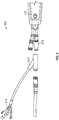
- FIG. 1A illustrates a side view of a bicycle 100, such as an electric bicycle.
- the bicycle 100 can include a seat 105 and a frame 110.
- the seat 105 can be supported by a seat tube 115.
- An electronic device 112 can be mounted to the frame 110 and positioned at least partly in a top tube of the frame 110 that extends between the seat tube 115 and handle bar mount.
- the bicycle 100 also can include a rear axle 120 of a rear wheel assembly 125.
- a motor can be positioned proximate the rear wheel assembly 125 for imparting motion to the bicycle 100, and one or more sensors can be positioned proximate the rear wheel assembly 125 or the front wheel assembly for monitoring operations or properties of the bicycle 100.
- a remote control device 130 can be attached to handle bars of the bicycle 100 and used to control the electronic device 112.
- Figure 1B illustrates a view of the bicycle 100 of Figure 1A from the perspective of a rider sitting in the seat 105 and viewing the handle bars and the electronic device 112 mounted to the top tube.
- FIG 2A illustrates a top perspective view of the electronic device 112 of Figure 1A .
- the electronic device 112 includes a housing that has an upper portion 201 and a lower portion 202.
- the lower portion 202 can be positioned within the frame 110 and the upper portion 201 can be positioned above the frame 110 and visible when viewing an outer surface of the bicycle 100.
- the upper portion 201 can include a downward sloping portion 203 and an inwardly sloping portion 204.
- the upper portion 201 may include a hole 206 usable for securing the upper portion 201 to the frame 110 with a fastener like a bolt or screw.
- the lower portion 202 can include a spring 208 configured to press against an inner surface of the frame 110 to secure the electronic device 112 to the top tube.
- the spring 208 can, for example, be a plate spring.
- the lower portion 202 can additionally include a connector 210.
- the connector 210 can be an analog connector and may include a first cable 212 (such as a HIGO 6-pole female cable) and a second cable 214 (such as a HIGO 5-pole male cable) for receiving data or power from or transmitting data or power to the bicycle 100 or one or more other components associated with the bicycle.
- the upper portion 201 can include a first user interface element 220 and a second user interface element 222.
- the first user interface element 220 can, for example, be used to receive a user input to activate or deactivate the bicycle 100, such as a motor of the bicycle 100 or one or more components associated with the bicycle 100.
- the second user interface element 222 can, for instance, be used to receive a user input to switch modes for the bicycle 100 or one or more other components associated with the bicycle 100.
- the upper portion 201 can further include a first display area 230 and a second display area 232.
- the first display area 230 can be used to display a level of charge of one or more batteries associated with (for example, supported by) the bicycle 100, such as is described in greater detail with respect to Figure 6 .
- the second display area 232 can be used to indicate whether the electronic device 112 or the bicycle 100 is activated or to identify a mode of operation for the electronic device 112 or the bicycle 100.
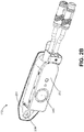
- Figure 2B illustrates a bottom perspective view of the electronic device 112 of Figure 1A .
- the lower portion 202 can include a speaker 240, such as a beeper, for outputting information audibly to an operator.
- a speaker 240 such as a beeper
- Figures 2C and 2D illustrate side perspective views of the electronic device 112 of Figure 1A .
- the spring 208 can include a point 209 that is configured to contact and apply force against the inner surface of the frame 110 to secure the electronic device 112 to the frame 110.
- the electronic device 112 can include a diagnostic port positioned behind a cover 250 as shown in Figures 2C and 2D .
- the diagnostic port can be used to service and perform diagnostics on electronic device 112, the bicycle 100, or one or more components associated with the bicycle 100.
- the diagnostic port can be a Universal Serial Bus (USB) port.
- USB Universal Serial Bus
- FIG 3A illustrates an environment 300 in which the electronic device 112 of Figure 1A may communicate with other devices.
- the electronic device 112 can communicate via a medium, such as a Controller Area Network (CAN bus) or other channel, with a torque sensor 310, a motor controller 312, one or more batteries 314, and one or more additional components 316.
- the electronic device 112 can additionally communicate via wired or wireless communications with the remote control device 130, a personal computer 320, a smart phone 322, and a display 324.
- a medium such as a Controller Area Network (CAN bus) or other channel
- the electronic device 112 can receive a torque signal from the torque sensor 310 that is indicative of a torque at the rear axle 120 or another part of the bicycle 100.
- the electronic device 112 may communicate with the motor controller 312 so that the electronic device 112 can monitor operations or properties of the motor controller 312 or provide control commands to adjust operations by the motor controller 312.
- the electronic device 112 can receive one or more batteries signals from the one or more batteries 314 that is indicative of a level of charge of the one or more batteries 314.
- the one or more batteries 314 can include two batteries, and the electronic device can receive one battery signal from each of the two batteries to determine the level of charge of the individual batteries.
- FIG 3B illustrates an example components of the electronic device 112 of Figure 1A .
- the electronic device 112 can include a processor 330, a memory device 332, a user interface 334, a communication interface 336, and a Global Positioning System (GPS) antenna 338.
- the processor 330 can control operations of the electronic device 112 according to executable instructions stored in the memory device 332.
- the processor 330 may also store gathered bike data to the memory device 332.
- the user interface 334 can receive user inputs from an operator, such as via selection of the first user interface element 220 and the second user interface element 222 by the operator.
- the communication interface 336 can facilitate wired or wireless communications between the electronic device 112 and other devices.
- the GPS antenna 338 can provide a location of the electronic device 112, such as geographical coordinates corresponding to the location of the electronic device 112 over time.
- Figures 4A and 4B illustrate perspective views of the remote control device 130.
- the remote control device 130 can be attached to the handle bars of the bicycle 100 by positioning and securing the handle bars in the hole 410.
- the remote control device 130 can include multiple remote user interface elements, including a first remote user interface element 420, a second remote user interface element 422, and a third remote user interface element 424 for receiving user inputs to control operations of the electronic device 112.
- the remote control device 130 can transmit control signals to the electronic device 112 via a connector 430 of the remote control device 130.
- Each of the first remote user interface element 420, the second remote user interface element 422, and the third remote user interface element 42 can, for instance, include a switch that connects a different data wire to ground when the switch is pressed.
- the remote control device 130 may not include any transistors or intelligent components, such as a microprocessor.
- the remote control device 130 can include a top housing 440, rubber keys 442, internal plugs 444, flexible printed circuits (FPCs) with clickers 446, a bottom housing 448, a seal plug 450, a nut plate 452, a screw 454, a bushing 456, and a cable 458.
- FPCs flexible printed circuits
- Figure 5 illustrates a configuration 500 for connecting one or more lights to the electronic device 112 of Figure 1A .
- the first cable 212 can be connected to a Y splitter 510.
- the ends 512 of the Y splitter 510 can be connected to the one or more lights and provide voltage and ground wires for the one or more lights.
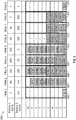
- FIG 6 illustrates battery status displays 600 by the electronic device 112 of Figure 1A .
- the battery status displays 600 in particular can be presented in the first display area 230 shown in Figure 2A .
- the Battery 1 State of Charge Percentage (SOC%) row and the Battery 2 SOC% row indicate the state of charge (sometimes referred to as a level of charge) of battery 1 and battery 2 over times 1-9 as numerical percentages. For example, at times 3, 7, and 9, battery 1 can respectively have a state of charge of 100%, 20%, and 7%, and at times 3, 7, and 9, battery 2 can respectively have a state of charge of 100%, 100%, and 5%.
- the 1-10 rows indicate the state of charge of the two batteries in the form of activated, colored indicators (such as LEDs) that correspond to the numerical percentages listed in the corresponding time column.
- a presented scale for battery 1 may be different from the presented scale for battery 2 (for instance, 100% state of charge for battery 1 can be indicated by activating all 1-10 of the indicators so each indicator represents an around 10% increase in charge while 100% state of charge for battery 2 can be indicated by activating all 1-5 of the bottom indicators so that each indicator represents an around 20% increase in charge).
- the indicators for battery 1 can be presented in a different color from the indicators for battery 2.
- all 1-10 of the blue indicators can be activated corresponding to the 100% state of charge for battery 1, and all 1-5 of the green indicators can be activated corresponding to the 100% state of charge for battery 2.
- 1 and 2 of the blue indicators can be activated corresponding to the 20% state of charge for battery 1, and all 1-5 of the green indicators can be activated corresponding to the 100% state of charge for battery 2.
- a single combined red indicator can be presented indicating that both batteries are below threshold levels, such as a 10% state of charge.
- the first display area 230 can appear as shown in box 602.
- the first display area 230 can appear as shown in box 604.
- the first display area 230 can appear as shown in box 606.
- the first display area 230 can appear as shown in box 608.
- the first display area 230 can appear as shown in box 610.
- the first display area 230 can appear as shown in box 612.
- the first display area 230 can appear as shown in box 614.
- the first display area 230 can appear as shown in box 616.
- the first display area 230 can appear as shown in box 618.
- the first display area 230 can simultaneously present the state of charges of battery 1 and battery 2 so that the state of charge of one of battery 1 or battery 2 is overlaid on the state of charge of the other of battery 1 or battery 2.
- the first display area 230 can moreover present the state of charges of battery 1 and battery 2 such that the battery having the lower state of charge is shown overlaid on top.
- the battery having the higher state of charge may instead by shown overlaid on top.
- the state of charge of one of battery 1 or battery 2 may be presented with a smaller width than the state of charge of the other of battery 1 or battery 2 (for example, as illustrated where the state of charge of battery 1 has a smaller width than the state of charge of battery 2).
- a machine such as a general purpose processor, a digital signal processor (DSP), an application specific integrated circuit (ASIC), a field programmable gate array (FPGA) or other programmable logic device, discrete gate or transistor logic, discrete hardware components, or any combination thereof designed to perform the functions described herein.
- DSP digital signal processor
- ASIC application specific integrated circuit
- FPGA field programmable gate array
- a general purpose processor can be a microprocessor, but in the alternative, the processor can be a controller, microcontroller, or state machine, combinations of the same, or the like.
- a processor can also be implemented as a combination of computing devices, for example, a combination of a DSP and a microprocessor, a plurality of microprocessors, one or more microprocessors in conjunction with a DSP core, or any other such configuration.
- a software module can reside in RAM memory, flash memory, ROM memory, EPROM memory, EEPROM memory, registers, hard disk, a removable disk, a CD-ROM, or any other form of computer-readable storage medium known in the art.
- An example storage medium can be connected to the processor such that the processor can read information from, and write information to, the storage medium.
- the storage medium can be integral to the processor.
- the processor and the storage medium can reside in an ASIC.
- the ASIC can reside in a user terminal.
- the processor and the storage medium can reside as discrete components in a user terminal.
Landscapes
- Engineering & Computer Science (AREA)
- Mechanical Engineering (AREA)
- Computer Hardware Design (AREA)
- Physics & Mathematics (AREA)
- General Physics & Mathematics (AREA)
- Theoretical Computer Science (AREA)
- General Engineering & Computer Science (AREA)
- Human Computer Interaction (AREA)
- Electric Propulsion And Braking For Vehicles (AREA)
- Charge And Discharge Circuits For Batteries Or The Like (AREA)
- Battery Mounting, Suspending (AREA)
- Measuring Fluid Pressure (AREA)
Priority Applications (1)
| Application Number | Priority Date | Filing Date | Title |
|---|---|---|---|
| EP21161260.1A EP3851365B1 (de) | 2018-06-28 | 2019-06-27 | Im rahmen montierte fahrradüberwachungsvorrichtung |
Applications Claiming Priority (1)
| Application Number | Priority Date | Filing Date | Title |
|---|---|---|---|
| US16/022,507 US10472015B1 (en) | 2018-06-28 | 2018-06-28 | In-frame mounted bicycle monitoring device |
Related Child Applications (1)
| Application Number | Title | Priority Date | Filing Date |
|---|---|---|---|
| EP21161260.1A Division EP3851365B1 (de) | 2018-06-28 | 2019-06-27 | Im rahmen montierte fahrradüberwachungsvorrichtung |
Publications (3)
| Publication Number | Publication Date |
|---|---|
| EP3587236A2 true EP3587236A2 (de) | 2020-01-01 |
| EP3587236A3 EP3587236A3 (de) | 2020-03-11 |
| EP3587236B1 EP3587236B1 (de) | 2021-03-24 |
Family
ID=67137526
Family Applications (2)
| Application Number | Title | Priority Date | Filing Date |
|---|---|---|---|
| EP21161260.1A Active EP3851365B1 (de) | 2018-06-28 | 2019-06-27 | Im rahmen montierte fahrradüberwachungsvorrichtung |
| EP19182784.9A Active EP3587236B1 (de) | 2018-06-28 | 2019-06-27 | Im rahmen montierte fahrradüberwachungsvorrichtung |
Family Applications Before (1)
| Application Number | Title | Priority Date | Filing Date |
|---|---|---|---|
| EP21161260.1A Active EP3851365B1 (de) | 2018-06-28 | 2019-06-27 | Im rahmen montierte fahrradüberwachungsvorrichtung |
Country Status (2)
| Country | Link |
|---|---|
| US (4) | US10472015B1 (de) |
| EP (2) | EP3851365B1 (de) |
Cited By (3)
| Publication number | Priority date | Publication date | Assignee | Title |
|---|---|---|---|---|
| EP3882121A1 (de) * | 2020-03-20 | 2021-09-22 | Amprio GmbH | Elektrofahrrad und modulare elektrofahrrad-traktionsbatterie |
| US12545357B2 (en) | 2018-06-28 | 2026-02-10 | Specialized Bicycle Components, Inc. | In-frame mounted bicycle monitoring device |
| US12589822B2 (en) | 2021-05-25 | 2026-03-31 | Specialized Bicycle Components, Inc. | In-frame mounted bicycle display |
Families Citing this family (24)
| Publication number | Priority date | Publication date | Assignee | Title |
|---|---|---|---|---|
| US9452654B2 (en) | 2009-01-07 | 2016-09-27 | Fox Factory, Inc. | Method and apparatus for an adjustable damper |
| US9140325B2 (en) | 2009-03-19 | 2015-09-22 | Fox Factory, Inc. | Methods and apparatus for selective spring pre-load adjustment |
| US12491961B2 (en) * | 2008-11-25 | 2025-12-09 | Fox Factory, Inc. | Seat post |
| US9422018B2 (en) * | 2008-11-25 | 2016-08-23 | Fox Factory, Inc. | Seat post |
| US10036443B2 (en) | 2009-03-19 | 2018-07-31 | Fox Factory, Inc. | Methods and apparatus for suspension adjustment |
| US11299233B2 (en) | 2009-01-07 | 2022-04-12 | Fox Factory, Inc. | Method and apparatus for an adjustable damper |
| EP3778358B1 (de) | 2010-07-02 | 2023-04-12 | Fox Factory, Inc. | Einstellbare sattelstütze mit positiver verriegelung |
| EP3567272B1 (de) | 2011-09-12 | 2021-05-26 | Fox Factory, Inc. | Verfahren und vorrichtung zur aufhängungseinstellung |
| ES2863405T3 (es) * | 2018-06-27 | 2021-10-11 | Polar Electro Oy | Ciclocomputador |
| JP2020098124A (ja) * | 2018-12-17 | 2020-06-25 | セイコーエプソン株式会社 | 電子機器、バッテリー状態表示方法および印刷装置 |
| US12246795B2 (en) * | 2019-11-26 | 2025-03-11 | Sram, Llc | Interface for electric assist bicycle |
| USD1099881S1 (en) * | 2020-05-28 | 2025-10-28 | Sram, Llc | Combined electronic device and mounting interface |
| TW202241750A (zh) | 2021-04-20 | 2022-11-01 | 德商矢倫德國股份有限公司 | 電動自行車驅動單元以及用於電動自行車驅動單元的自行車車架、車架接口單元和蓄能器裝置 |
| JP7220759B1 (ja) * | 2021-09-30 | 2023-02-10 | 本田技研工業株式会社 | 搭乗型移動体、搭乗型移動体の制御装置、制御方法、及びプログラム |
| DE102022109790A1 (de) * | 2022-04-22 | 2023-10-26 | Porsche eBike Perfomance GmbH | Fahrrad- oder E-Bike-Schnittstelle und Fahrrad oder E-Bike |
| US12414170B2 (en) | 2022-11-30 | 2025-09-09 | Sram, Llc | Power on pairing for electronic components of a bicycle |
| CN219619280U (zh) * | 2023-03-10 | 2023-09-01 | 深圳市十方运动科技有限公司 | 一种管内嵌式gps盒安装锁紧结构 |
| DE102023205672A1 (de) | 2023-06-16 | 2024-12-19 | Mahle International Gmbh | Bediengerät für ein Elektrofahrrad sowie Elektrofahrrad mit demselben |
| USD1096783S1 (en) * | 2023-07-12 | 2025-10-07 | Specialized Bicycle Components, Inc. | Display screen or portion thereof with animated graphical user interface |
| DE102024201931A1 (de) * | 2024-03-01 | 2025-09-04 | Robert Bosch Gesellschaft mit beschränkter Haftung | Elektromotorisch angetriebenes Fahrzeug und Anzeigeeinheit für ein elektromotorisch angetriebenes Fahrzeug |
| DE102024201936A1 (de) * | 2024-03-01 | 2025-09-04 | Robert Bosch Gesellschaft mit beschränkter Haftung | Elektromotorisch angetriebenes Fahrzeug und Anzeigeeinheit für ein elektromotorisch angetriebenes Fahrzeug |
| DE102024201940A1 (de) * | 2024-03-01 | 2025-09-04 | Robert Bosch Gesellschaft mit beschränkter Haftung | Elektromotorisch angetriebenes Fahrzeug und Anzeigeeinheit für ein elektromotorisch angetriebenes Fahrzeug |
| US12606271B2 (en) | 2024-08-26 | 2026-04-21 | Sram, Llc | System for a bicycle including an energy storage device |
| DE102024131067A1 (de) | 2024-10-24 | 2026-04-30 | Mahle International Gmbh | Bediengerät für ein Elektrofahrrad, Fahrradrahmen sowie Elektrofahrrad mit einem solchen Bediengerät |
Family Cites Families (111)
| Publication number | Priority date | Publication date | Assignee | Title |
|---|---|---|---|---|
| FR730602A (fr) | 1932-01-27 | 1932-08-18 | Dispositif de montage pour montres de motocyclettes et autres véhicules analogues | |
| US2596438A (en) | 1951-11-30 | 1952-05-13 | Security Sash & Screen Company | Spring clip |
| DE4105505A1 (de) | 1991-02-22 | 1992-09-03 | Telefonbau & Normalzeit Gmbh | Anzeigevorrichtung mit einer fluessigkristallanzeige |
| US5178033A (en) | 1991-09-03 | 1993-01-12 | August Kund | Bicycle gear display |
| DE9204615U1 (de) | 1992-04-03 | 1992-06-04 | Tsai, Shui Te, Chang-Hua City | Befestigungsvorrichtung für Messgerät |
| DE4427173C1 (de) | 1994-08-01 | 1995-10-19 | Valeo Borg Instr Verw Gmbh | Anzeigegerät mit elektrooptischer Zelle, insbesondere für ein Kraftfahrzeug-Armaturenbrett |
| JPH08268361A (ja) * | 1995-03-30 | 1996-10-15 | Matsushita Electric Ind Co Ltd | 電動自転車 |
| US5798702A (en) | 1996-04-18 | 1998-08-25 | Suzuki Motor Corporation | Residual battery capacity display device for electric vehicle |
| US6305241B1 (en) | 1999-06-28 | 2001-10-23 | Shimano, Inc. | Handlebar adapter for mounting a bicycle display |
| US6854328B2 (en) | 2001-06-14 | 2005-02-15 | Custom Spec Engineering, Inc. | Cover structure for marine instrument |
| JP2003116226A (ja) * | 2001-10-10 | 2003-04-18 | Matsushita Electric Ind Co Ltd | 電動車両および電動車両用バッテリーユニットの充電装置 |
| USD472834S1 (en) | 2001-11-28 | 2003-04-08 | Cateye Co., Ltd. | Speedometer for a bicycle |
| JP3727315B2 (ja) * | 2003-04-01 | 2005-12-14 | 株式会社シマノ | 自転車用電源装置 |
| TWD104499S1 (zh) | 2003-08-25 | 2005-05-11 | 貓眼股份有限公司 | 自行車用速度計 |
| TWD104498S1 (zh) | 2003-08-25 | 2005-05-11 | 貓眼股份有限公司 | 自行車用速度表 |
| USD522394S1 (en) | 2004-08-30 | 2006-06-06 | Cateye Co., Ltd. | Speedometer for a bicycle |
| US20070052100A1 (en) | 2005-09-07 | 2007-03-08 | Nokia Corporation | Spring clip for a portable electronic device |
| USD553528S1 (en) | 2005-09-27 | 2007-10-23 | Cateye Co., Ltd. | Speedometer for a bicycle |
| USD554014S1 (en) | 2006-08-29 | 2007-10-30 | Cat Eye Co., Ltd. | Speedometer for a bicycle |
| TWM316210U (en) * | 2007-03-16 | 2007-08-01 | Ideal Bike Corp | Power apparatus for electric bicycle |
| US7878521B2 (en) * | 2007-04-16 | 2011-02-01 | Trek Bicycle Corporation | Bicycle frame with device cavity |
| KR100886381B1 (ko) * | 2007-09-06 | 2009-03-02 | 김기수 | 원격조정 송수신장치 |
| US20090091292A1 (en) * | 2007-10-04 | 2009-04-09 | Brookshire Innovations, Llc | Motor cycle cell phone power adapter charging system |
| ITMI20072407A1 (it) * | 2007-12-20 | 2009-06-21 | Campagnolo Srl | Apparecchiatura elettronica per bicicletta |
| US9422018B2 (en) * | 2008-11-25 | 2016-08-23 | Fox Factory, Inc. | Seat post |
| US8364389B2 (en) | 2009-02-02 | 2013-01-29 | Apple Inc. | Systems and methods for integrating a portable electronic device with a bicycle |
| FI20095888A0 (fi) | 2009-08-28 | 2009-08-28 | Polar Electro Oy | Pyöräilytietokone |
| USD637508S1 (en) | 2009-09-10 | 2011-05-10 | Cateye Co., Ltd. | Measuring instrument for bicycle |
| USD640608S1 (en) | 2010-07-01 | 2011-06-28 | Panasonic Corporation | Operation switch for battery-assisted bicycle |
| US8469381B2 (en) * | 2010-08-26 | 2013-06-25 | Cycling Sports Group, Inc. | Bicycle |
| JP5564390B2 (ja) * | 2010-09-30 | 2014-07-30 | 本田技研工業株式会社 | 電動補助自転車の制御装置 |
| USD665685S1 (en) | 2010-10-07 | 2012-08-21 | Cateye Co., Ltd. | Data logger |
| US8531072B2 (en) | 2011-02-16 | 2013-09-10 | E-Wish Technology, Llc | Dual-mode counter-rotating-to-traditional electric motor and system |
| US10086708B2 (en) * | 2011-03-31 | 2018-10-02 | Shimano Inc. | Bicycle component control apparatus |
| EP2532571B1 (de) * | 2011-06-10 | 2014-03-26 | Campagnolo S.r.l. | Am Fahrrad befestigte Vorrichtung und zugehöriges Montageverfahren |
| USD680890S1 (en) | 2011-08-26 | 2013-04-30 | Cateye Co., Ltd. | Speedometer for a bicycle |
| USD674322S1 (en) | 2011-08-29 | 2013-01-15 | Saris Cycling Group, Inc. | Handlebar mount for a bicycle computer |
| US9119295B2 (en) | 2011-10-11 | 2015-08-25 | Rockwell Automation Technologies, Inc. | Display mounting techniques |
| US8979110B2 (en) * | 2012-03-16 | 2015-03-17 | Specialized Bicycle Components, Inc. | Bicycle with battery mount |
| TWM448435U (zh) * | 2012-07-10 | 2013-03-11 | Shimano Kk | 自行車部件之控制裝置 |
| USD711755S1 (en) | 2012-07-17 | 2014-08-26 | Robert Bosch Gmbh | Cyclometer |
| USD704583S1 (en) | 2012-11-01 | 2014-05-13 | Cateye Co., Ltd. | Speedometer for a bicycle |
| US9254409B2 (en) * | 2013-03-14 | 2016-02-09 | Icon Health & Fitness, Inc. | Strength training apparatus with flywheel and related methods |
| GB201311001D0 (en) * | 2013-06-20 | 2013-08-07 | Lucabella Holdings Llc | Lucabella |
| USD727768S1 (en) | 2013-06-28 | 2015-04-28 | Cateye Company, Ltd. | Speedometer for a bicycle |
| US9191038B2 (en) * | 2013-12-24 | 2015-11-17 | Shimano Inc. | Wireless bicycle communication apparatus and wireless bicycle communication system |
| USD743824S1 (en) | 2014-01-08 | 2015-11-24 | Polar Electro Oy | Cyclometer |
| US9194955B1 (en) * | 2014-01-16 | 2015-11-24 | WI-MM Corporation | Cloud based activity monitor for bicycles with fleet management and rider analytics system |
| US9604689B2 (en) | 2014-07-16 | 2017-03-28 | Ford Global Technologies, Llc | Bicycle frame joint locking mechanism |
| TW201617583A (zh) | 2014-08-05 | 2016-05-16 | 福柏克智慧財產有限責任公司 | 單車、用於單車的控制器以及控制單車的變速器的方法 |
| TWD172358S (zh) | 2014-10-15 | 2015-12-11 | 貓眼股份有限公司 | 自行車用速度計 |
| US20170334522A1 (en) | 2014-11-18 | 2017-11-23 | Vanhawks Inc. | Network-enabled bicycles, bicycles interconnected into a mesh network, electronic devices for bicycles and related methods |
| DE102015211782B4 (de) * | 2014-12-31 | 2020-07-23 | Lenovo (Beijing) Co., Ltd. | Elektronisches Gerät und Verfahren zum Steuern einer Energieversorgung des elektronischen Gerätes |
| USD810733S1 (en) | 2015-04-15 | 2018-02-20 | Samsung Electronics Co., Ltd. | Electronic device |
| DE202015002905U1 (de) * | 2015-04-22 | 2015-05-10 | Hubert Dummler | Antriebsvorrichtung eines Elektro-Fahrrads (E-Bikes) |
| USD772746S1 (en) | 2015-06-08 | 2016-11-29 | Garmin Switzerland Gmbh | Electronic device |
| USD777591S1 (en) | 2015-06-18 | 2017-01-31 | Polar Electro Oy | Bike computer |
| CN104908864B (zh) | 2015-07-13 | 2017-09-26 | 吴俊斌 | 一种用于智能自行车的导航装置 |
| CN105882822A (zh) | 2015-08-11 | 2016-08-24 | 乐视体育文化产业发展(北京)有限公司 | 一种头机及智能自行车 |
| CN105882799A (zh) | 2015-08-11 | 2016-08-24 | 乐视体育文化产业发展(北京)有限公司 | 一种自行车及其驻车控制装置 |
| US20200207435A1 (en) | 2015-08-14 | 2020-07-02 | Volata Cycles, Inc. | Bicycle with integrated electronic components |
| US9685986B2 (en) * | 2015-11-05 | 2017-06-20 | Htc Corporation | Device cover for accessory attachment |
| CN205220948U (zh) | 2015-11-12 | 2016-05-11 | 天津市天鹿自行车有限公司 | 一种具有可拆卸防损模块结构的自行车车架 |
| US10118660B2 (en) | 2016-05-14 | 2018-11-06 | Peter Cooper | Smartpack device for a bike |
| CN205872330U (zh) | 2016-06-30 | 2017-01-11 | 苏州达方电子有限公司 | 电动自行车 |
| USD852677S1 (en) | 2016-07-18 | 2019-07-02 | Trek Bicycle Corporation | Bicycle display |
| WO2018022867A1 (en) | 2016-07-27 | 2018-02-01 | F3 Cycling LLC | Universal stem-mounted bicycle computer mount |
| PL3281855T3 (pl) * | 2016-08-10 | 2020-08-24 | BH Bikes Europe, S.L. | Rama roweru elektrycznego oraz rower elektryczny |
| JP6720034B2 (ja) * | 2016-09-15 | 2020-07-08 | ヤマハ発動機株式会社 | 電動補助自転車 |
| CN106379472A (zh) | 2016-11-16 | 2017-02-08 | 浙江途尔车业有限公司 | 一种电动自行车一体化车架结构 |
| CN106428377B (zh) | 2016-12-09 | 2022-03-25 | 广东技术师范学院 | 自行车把手结构以及电动自行车 |
| US10475303B2 (en) * | 2017-03-16 | 2019-11-12 | Shimano Inc. | Bicycle electric device |
| TWI644815B (zh) | 2017-03-23 | 2018-12-21 | 綠點高新科技股份有限公司 | 智能自行車車把及其中控裝置 |
| US10773769B2 (en) * | 2017-04-03 | 2020-09-15 | Shimano Inc. | Bicycle drive system, bicycle drive unit, and bicycle battery unit |
| CN108860402B (zh) * | 2017-05-12 | 2023-11-07 | 京东方科技集团股份有限公司 | 车载显示系统以及车辆 |
| US20210039737A1 (en) | 2017-05-18 | 2021-02-11 | Carla Marie Montez | Handlebar Systems and Method |
| US10858061B2 (en) | 2017-05-18 | 2020-12-08 | Carla Marie Montez | Integrated handlebar system and method |
| US10812645B2 (en) | 2017-05-18 | 2020-10-20 | Carla Marie Montez | Handlebar systems and method |
| US10442488B2 (en) * | 2017-06-29 | 2019-10-15 | Shimano Inc. | Bicycle electrical component |
| US10392020B2 (en) * | 2017-07-07 | 2019-08-27 | Shimano Inc. | Bicycle component control system |
| DE202017104230U1 (de) * | 2017-07-14 | 2018-10-16 | Zeg Zweirad-Einkaufs-Genossenschaft Eg | Fahrradrahmen für Elektrofahrräder, und Elektrofahrrad hiermit |
| CH714099A2 (de) | 2017-08-29 | 2019-03-15 | Mystromer Ag | Elektrofahrrad mit Kommunikationssystem. |
| CH714097B1 (de) | 2017-08-29 | 2022-01-31 | Mystromer Ag | Klimatisierungsvorrichtung für ein Elektrofahrrad. |
| CN109501920A (zh) | 2017-09-15 | 2019-03-22 | 微程式资讯股份有限公司 | 具营运系统的自行车智能车把 |
| NL2020781B1 (nl) * | 2018-04-17 | 2019-10-24 | Vanmoof Bv | Rijwiel met lichtsysteem, rijwielbuiscassette en werkwijze |
| DE102018206821A1 (de) * | 2018-05-03 | 2019-11-07 | YT Industries GmbH | Set mit einer Akkueinheit und einer Aufnahmeeinrichtung zur Aufnahme der Akkueinheit |
| TWI641521B (zh) | 2018-06-19 | 2018-11-21 | 達方電子股份有限公司 | 連接器及電動自行車 |
| CN109018147B (zh) | 2018-06-27 | 2021-06-08 | 苏州达方电子有限公司 | 连接器及电动自行车 |
| USD891991S1 (en) | 2018-06-28 | 2020-08-04 | Specialized Bicycle Components, Inc. | Electronic device |
| US10472015B1 (en) | 2018-06-28 | 2019-11-12 | Specialized Bicycle Components, Inc. | In-frame mounted bicycle monitoring device |
| US11124259B2 (en) | 2018-08-21 | 2021-09-21 | Specialized Bicycle Components, Inc. | Bicycle with housing loop stay |
| KR20210111267A (ko) | 2019-01-08 | 2021-09-10 | 카를라 마리 몬테즈 | 핸들바 시스템 및 방법 |
| US12246795B2 (en) | 2019-11-26 | 2025-03-11 | Sram, Llc | Interface for electric assist bicycle |
| DE102020200020B4 (de) | 2020-01-03 | 2026-02-19 | Smartscale NewCo AG | Anzeigeeinheit, Anzeigeneinheitenset und Elektrofahrrad |
| KR20210143480A (ko) | 2020-05-20 | 2021-11-29 | 주식회사 엠이알아이티 | 디스플레이 일체형 핸들바 |
| CN212766602U (zh) | 2020-09-08 | 2021-03-23 | 惠州捷冠科技有限公司 | 一种轻便折叠电动自行车 |
| JP7828139B2 (ja) | 2021-02-02 | 2026-03-11 | ヤマハ発動機株式会社 | 電動補助自転車用の表示装置、及び電動補助自転車 |
| WO2022167372A1 (de) | 2021-02-04 | 2022-08-11 | Sabrina Gwendolin Fischer | Fahrradlenker mit integriertem display |
| DE102021120276B4 (de) | 2021-02-04 | 2025-07-17 | FLITE GmbH | Fahrradlenker mit integriertem Display ("FLITEDECK") |
| US12589822B2 (en) | 2021-05-25 | 2026-03-31 | Specialized Bicycle Components, Inc. | In-frame mounted bicycle display |
| DE102021205911A1 (de) | 2021-06-10 | 2022-12-15 | Mahle International Gmbh | Bediengerät und Elektrofahrrad |
| TW202304735A (zh) | 2021-07-30 | 2023-02-01 | 日商島野股份有限公司 | 人力驅動車用之操作裝置及人力驅動車 |
| DE102021209424B4 (de) | 2021-08-27 | 2024-08-01 | Zf Friedrichshafen Ag | Leistungs-Verteileinheit für ein elektrisches Fahrrad sowie Fahrrad |
| US11623710B2 (en) | 2021-09-02 | 2023-04-11 | Rudi Pienaar | Handlebar apparatus with an integral electronic device for a bicycle |
| CN216332505U (zh) | 2021-10-18 | 2022-04-19 | 英腾运动科技(苏州)有限公司 | 一种电动助力自行车用上管式电量显示控制装置 |
| CN216508802U (zh) | 2021-12-21 | 2022-05-13 | 八方电气(苏州)股份有限公司 | 电动自行车显示仪表及安装结构 |
| DE102022106780B4 (de) | 2022-03-23 | 2024-02-01 | Piepenstock Metall Systeme GmbH | Klemmschelle zur Fixierung einer Bedien- oder Anzeigeeinheit an einem rohrförmigen Teil eines Fahrrads, Bedien- oder Anzeigeeinheit sowie Fahrrad |
| DE102022109790A1 (de) | 2022-04-22 | 2023-10-26 | Porsche eBike Perfomance GmbH | Fahrrad- oder E-Bike-Schnittstelle und Fahrrad oder E-Bike |
| DE102022206633A1 (de) | 2022-06-30 | 2024-01-04 | Robert Bosch Gesellschaft mit beschränkter Haftung | Anzeige- und/oder Bedienvorrichtung |
| CH719877A1 (de) | 2022-07-08 | 2024-01-15 | Mystromer Ag | Vorrichtung und Verfahren zur Ver- und Entriegelung für ein elektrisch angetriebenes Fahrzeug. |
| DE202023103043U1 (de) | 2023-06-02 | 2023-06-23 | Biketec Gmbh | Bedienschnittstelle und Elektrofahrrad mit einer Bedienschnittstelle |
-
2018
- 2018-06-28 US US16/022,507 patent/US10472015B1/en active Active
-
2019
- 2019-06-27 EP EP21161260.1A patent/EP3851365B1/de active Active
- 2019-06-27 EP EP19182784.9A patent/EP3587236B1/de active Active
- 2019-10-31 US US16/670,872 patent/US10933936B2/en active Active
-
2021
- 2021-02-26 US US17/187,288 patent/US11820456B2/en active Active
-
2023
- 2023-10-17 US US18/488,367 patent/US12545357B2/en active Active
Cited By (3)
| Publication number | Priority date | Publication date | Assignee | Title |
|---|---|---|---|---|
| US12545357B2 (en) | 2018-06-28 | 2026-02-10 | Specialized Bicycle Components, Inc. | In-frame mounted bicycle monitoring device |
| EP3882121A1 (de) * | 2020-03-20 | 2021-09-22 | Amprio GmbH | Elektrofahrrad und modulare elektrofahrrad-traktionsbatterie |
| US12589822B2 (en) | 2021-05-25 | 2026-03-31 | Specialized Bicycle Components, Inc. | In-frame mounted bicycle display |
Also Published As
| Publication number | Publication date |
|---|---|
| US10933936B2 (en) | 2021-03-02 |
| EP3851365B1 (de) | 2023-11-22 |
| US10472015B1 (en) | 2019-11-12 |
| US20200062327A1 (en) | 2020-02-27 |
| EP3851365A1 (de) | 2021-07-21 |
| US20210291923A1 (en) | 2021-09-23 |
| EP3587236A3 (de) | 2020-03-11 |
| US11820456B2 (en) | 2023-11-21 |
| US12545357B2 (en) | 2026-02-10 |
| US20240158041A1 (en) | 2024-05-16 |
| EP3587236B1 (de) | 2021-03-24 |
Similar Documents
| Publication | Publication Date | Title |
|---|---|---|
| US12545357B2 (en) | In-frame mounted bicycle monitoring device | |
| CN102730134B (zh) | 自行车部件控制设备 | |
| US11643165B2 (en) | Bicycle drive system, bicycle drive unit, and bicycle battery unit | |
| US10086907B2 (en) | Bicycle electrical component | |
| US20150009019A1 (en) | Bicycle control system | |
| CN105314050B (zh) | 自行车曲柄组件 | |
| US10822017B2 (en) | Integrated auto-steer system for vehicle | |
| JP2017222244A (ja) | 自転車用表示装置 | |
| WO2007139796A3 (en) | Systems and methods for image acquisition | |
| EP4387386A1 (de) | Elektrogerät mit einem kommunikationsmodul | |
| JP6333559B2 (ja) | 農作業機用制御装置 | |
| CN104648608B (zh) | 自行车电子系统 | |
| TWI781303B (zh) | 自行車電組件 | |
| US10513188B2 (en) | Rechargeable battery pack for electric or hybrid vehicles comprising a communication interface | |
| JP6509319B2 (ja) | 農作業機用リモコン操作装置 | |
| WO2015127967A1 (de) | Steuerungssystem für ein fahrzeug und verfahren zur steuerung eines fahrzeuges | |
| TW202340039A (zh) | 自行車電組件 | |
| JP5533123B2 (ja) | 太陽光発電システム | |
| US20210347261A1 (en) | Driver anti-distraction device (dadd) | |
| DE202016008499U1 (de) | Einrichtung zur Steuerung von elektronischen Komponenten eines Fahrzeugs, insbesondere Fahrrad oder Leichtfahrzeug, und zur Anzeige von Information | |
| CN110209234B (zh) | 电压处理电路 | |
| CN217227824U (zh) | 一种电动两轮车集成式控制器及新型电动两轮车 | |
| US20260054797A1 (en) | System for a bicycle including an energy storage device | |
| US20240300607A1 (en) | Method for controlling a motorcycle using a smart dashboard thereof and a mobile device | |
| KR102024650B1 (ko) | 전기적 경적 신호 전달 구조를 갖는 자율 주행용 스티어링 휠 |
Legal Events
| Date | Code | Title | Description |
|---|---|---|---|
| PUAI | Public reference made under article 153(3) epc to a published international application that has entered the european phase |
Free format text: ORIGINAL CODE: 0009012 |
|
| STAA | Information on the status of an ep patent application or granted ep patent |
Free format text: STATUS: THE APPLICATION HAS BEEN PUBLISHED |
|
| AK | Designated contracting states |
Kind code of ref document: A2 Designated state(s): AL AT BE BG CH CY CZ DE DK EE ES FI FR GB GR HR HU IE IS IT LI LT LU LV MC MK MT NL NO PL PT RO RS SE SI SK SM TR |
|
| AX | Request for extension of the european patent |
Extension state: BA ME |
|
| PUAL | Search report despatched |
Free format text: ORIGINAL CODE: 0009013 |
|
| AK | Designated contracting states |
Kind code of ref document: A3 Designated state(s): AL AT BE BG CH CY CZ DE DK EE ES FI FR GB GR HR HU IE IS IT LI LT LU LV MC MK MT NL NO PL PT RO RS SE SI SK SM TR |
|
| AX | Request for extension of the european patent |
Extension state: BA ME |
|
| RIC1 | Information provided on ipc code assigned before grant |
Ipc: B62K 19/40 20060101ALI20200204BHEP Ipc: B62M 6/90 20100101AFI20200204BHEP Ipc: B62J 99/00 20200101ALN20200204BHEP |
|
| STAA | Information on the status of an ep patent application or granted ep patent |
Free format text: STATUS: REQUEST FOR EXAMINATION WAS MADE |
|
| 17P | Request for examination filed |
Effective date: 20200319 |
|
| RBV | Designated contracting states (corrected) |
Designated state(s): AL AT BE BG CH CY CZ DE DK EE ES FI FR GB GR HR HU IE IS IT LI LT LU LV MC MK MT NL NO PL PT RO RS SE SI SK SM TR |
|
| REG | Reference to a national code |
Ref country code: DE Ref legal event code: R079 Ref document number: 602019003379 Country of ref document: DE Free format text: PREVIOUS MAIN CLASS: B62M0006900000 Ipc: B62J0050210000 |
|
| GRAP | Despatch of communication of intention to grant a patent |
Free format text: ORIGINAL CODE: EPIDOSNIGR1 |
|
| STAA | Information on the status of an ep patent application or granted ep patent |
Free format text: STATUS: GRANT OF PATENT IS INTENDED |
|
| RIC1 | Information provided on ipc code assigned before grant |
Ipc: B62K 19/40 20060101ALI20200917BHEP Ipc: B62J 50/21 20200101AFI20200917BHEP Ipc: B62J 50/22 20200101ALI20200917BHEP Ipc: B62J 43/00 20200101ALI20200917BHEP |
|
| INTG | Intention to grant announced |
Effective date: 20201020 |
|
| GRAS | Grant fee paid |
Free format text: ORIGINAL CODE: EPIDOSNIGR3 |
|
| GRAA | (expected) grant |
Free format text: ORIGINAL CODE: 0009210 |
|
| STAA | Information on the status of an ep patent application or granted ep patent |
Free format text: STATUS: THE PATENT HAS BEEN GRANTED |
|
| AK | Designated contracting states |
Kind code of ref document: B1 Designated state(s): AL AT BE BG CH CY CZ DE DK EE ES FI FR GB GR HR HU IE IS IT LI LT LU LV MC MK MT NL NO PL PT RO RS SE SI SK SM TR |
|
| REG | Reference to a national code |
Ref country code: GB Ref legal event code: FG4D |
|
| REG | Reference to a national code |
Ref country code: CH Ref legal event code: EP |
|
| REG | Reference to a national code |
Ref country code: IE Ref legal event code: FG4D |
|
| REG | Reference to a national code |
Ref country code: DE Ref legal event code: R096 Ref document number: 602019003379 Country of ref document: DE Ref country code: AT Ref legal event code: REF Ref document number: 1374228 Country of ref document: AT Kind code of ref document: T Effective date: 20210415 |
|
| REG | Reference to a national code |
Ref country code: LT Ref legal event code: MG9D |
|
| PG25 | Lapsed in a contracting state [announced via postgrant information from national office to epo] |
Ref country code: BG Free format text: LAPSE BECAUSE OF FAILURE TO SUBMIT A TRANSLATION OF THE DESCRIPTION OR TO PAY THE FEE WITHIN THE PRESCRIBED TIME-LIMIT Effective date: 20210624 Ref country code: HR Free format text: LAPSE BECAUSE OF FAILURE TO SUBMIT A TRANSLATION OF THE DESCRIPTION OR TO PAY THE FEE WITHIN THE PRESCRIBED TIME-LIMIT Effective date: 20210324 Ref country code: GR Free format text: LAPSE BECAUSE OF FAILURE TO SUBMIT A TRANSLATION OF THE DESCRIPTION OR TO PAY THE FEE WITHIN THE PRESCRIBED TIME-LIMIT Effective date: 20210625 Ref country code: FI Free format text: LAPSE BECAUSE OF FAILURE TO SUBMIT A TRANSLATION OF THE DESCRIPTION OR TO PAY THE FEE WITHIN THE PRESCRIBED TIME-LIMIT Effective date: 20210324 Ref country code: NO Free format text: LAPSE BECAUSE OF FAILURE TO SUBMIT A TRANSLATION OF THE DESCRIPTION OR TO PAY THE FEE WITHIN THE PRESCRIBED TIME-LIMIT Effective date: 20210624 |
|
| PG25 | Lapsed in a contracting state [announced via postgrant information from national office to epo] |
Ref country code: LV Free format text: LAPSE BECAUSE OF FAILURE TO SUBMIT A TRANSLATION OF THE DESCRIPTION OR TO PAY THE FEE WITHIN THE PRESCRIBED TIME-LIMIT Effective date: 20210324 Ref country code: SE Free format text: LAPSE BECAUSE OF FAILURE TO SUBMIT A TRANSLATION OF THE DESCRIPTION OR TO PAY THE FEE WITHIN THE PRESCRIBED TIME-LIMIT Effective date: 20210324 Ref country code: RS Free format text: LAPSE BECAUSE OF FAILURE TO SUBMIT A TRANSLATION OF THE DESCRIPTION OR TO PAY THE FEE WITHIN THE PRESCRIBED TIME-LIMIT Effective date: 20210324 |
|
| REG | Reference to a national code |
Ref country code: NL Ref legal event code: MP Effective date: 20210324 |
|
| REG | Reference to a national code |
Ref country code: AT Ref legal event code: MK05 Ref document number: 1374228 Country of ref document: AT Kind code of ref document: T Effective date: 20210324 |
|
| PG25 | Lapsed in a contracting state [announced via postgrant information from national office to epo] |
Ref country code: NL Free format text: LAPSE BECAUSE OF FAILURE TO SUBMIT A TRANSLATION OF THE DESCRIPTION OR TO PAY THE FEE WITHIN THE PRESCRIBED TIME-LIMIT Effective date: 20210324 |
|
| PG25 | Lapsed in a contracting state [announced via postgrant information from national office to epo] |
Ref country code: LT Free format text: LAPSE BECAUSE OF FAILURE TO SUBMIT A TRANSLATION OF THE DESCRIPTION OR TO PAY THE FEE WITHIN THE PRESCRIBED TIME-LIMIT Effective date: 20210324 Ref country code: EE Free format text: LAPSE BECAUSE OF FAILURE TO SUBMIT A TRANSLATION OF THE DESCRIPTION OR TO PAY THE FEE WITHIN THE PRESCRIBED TIME-LIMIT Effective date: 20210324 Ref country code: CZ Free format text: LAPSE BECAUSE OF FAILURE TO SUBMIT A TRANSLATION OF THE DESCRIPTION OR TO PAY THE FEE WITHIN THE PRESCRIBED TIME-LIMIT Effective date: 20210324 Ref country code: AT Free format text: LAPSE BECAUSE OF FAILURE TO SUBMIT A TRANSLATION OF THE DESCRIPTION OR TO PAY THE FEE WITHIN THE PRESCRIBED TIME-LIMIT Effective date: 20210324 Ref country code: SM Free format text: LAPSE BECAUSE OF FAILURE TO SUBMIT A TRANSLATION OF THE DESCRIPTION OR TO PAY THE FEE WITHIN THE PRESCRIBED TIME-LIMIT Effective date: 20210324 |
|
| PG25 | Lapsed in a contracting state [announced via postgrant information from national office to epo] |
Ref country code: IS Free format text: LAPSE BECAUSE OF FAILURE TO SUBMIT A TRANSLATION OF THE DESCRIPTION OR TO PAY THE FEE WITHIN THE PRESCRIBED TIME-LIMIT Effective date: 20210724 Ref country code: PL Free format text: LAPSE BECAUSE OF FAILURE TO SUBMIT A TRANSLATION OF THE DESCRIPTION OR TO PAY THE FEE WITHIN THE PRESCRIBED TIME-LIMIT Effective date: 20210324 Ref country code: PT Free format text: LAPSE BECAUSE OF FAILURE TO SUBMIT A TRANSLATION OF THE DESCRIPTION OR TO PAY THE FEE WITHIN THE PRESCRIBED TIME-LIMIT Effective date: 20210726 Ref country code: RO Free format text: LAPSE BECAUSE OF FAILURE TO SUBMIT A TRANSLATION OF THE DESCRIPTION OR TO PAY THE FEE WITHIN THE PRESCRIBED TIME-LIMIT Effective date: 20210324 Ref country code: SK Free format text: LAPSE BECAUSE OF FAILURE TO SUBMIT A TRANSLATION OF THE DESCRIPTION OR TO PAY THE FEE WITHIN THE PRESCRIBED TIME-LIMIT Effective date: 20210324 |
|
| REG | Reference to a national code |
Ref country code: DE Ref legal event code: R097 Ref document number: 602019003379 Country of ref document: DE |
|
| PG25 | Lapsed in a contracting state [announced via postgrant information from national office to epo] |
Ref country code: DK Free format text: LAPSE BECAUSE OF FAILURE TO SUBMIT A TRANSLATION OF THE DESCRIPTION OR TO PAY THE FEE WITHIN THE PRESCRIBED TIME-LIMIT Effective date: 20210324 Ref country code: AL Free format text: LAPSE BECAUSE OF FAILURE TO SUBMIT A TRANSLATION OF THE DESCRIPTION OR TO PAY THE FEE WITHIN THE PRESCRIBED TIME-LIMIT Effective date: 20210324 Ref country code: MC Free format text: LAPSE BECAUSE OF FAILURE TO SUBMIT A TRANSLATION OF THE DESCRIPTION OR TO PAY THE FEE WITHIN THE PRESCRIBED TIME-LIMIT Effective date: 20210324 Ref country code: ES Free format text: LAPSE BECAUSE OF FAILURE TO SUBMIT A TRANSLATION OF THE DESCRIPTION OR TO PAY THE FEE WITHIN THE PRESCRIBED TIME-LIMIT Effective date: 20210324 |
|
| PLBE | No opposition filed within time limit |
Free format text: ORIGINAL CODE: 0009261 |
|
| STAA | Information on the status of an ep patent application or granted ep patent |
Free format text: STATUS: NO OPPOSITION FILED WITHIN TIME LIMIT |
|
| PG25 | Lapsed in a contracting state [announced via postgrant information from national office to epo] |
Ref country code: SI Free format text: LAPSE BECAUSE OF FAILURE TO SUBMIT A TRANSLATION OF THE DESCRIPTION OR TO PAY THE FEE WITHIN THE PRESCRIBED TIME-LIMIT Effective date: 20210324 |
|
| 26N | No opposition filed |
Effective date: 20220104 |
|
| REG | Reference to a national code |
Ref country code: BE Ref legal event code: MM Effective date: 20210630 |
|
| PG25 | Lapsed in a contracting state [announced via postgrant information from national office to epo] |
Ref country code: LU Free format text: LAPSE BECAUSE OF NON-PAYMENT OF DUE FEES Effective date: 20210627 |
|
| PG25 | Lapsed in a contracting state [announced via postgrant information from national office to epo] |
Ref country code: IE Free format text: LAPSE BECAUSE OF NON-PAYMENT OF DUE FEES Effective date: 20210627 |
|
| PG25 | Lapsed in a contracting state [announced via postgrant information from national office to epo] |
Ref country code: IS Free format text: LAPSE BECAUSE OF FAILURE TO SUBMIT A TRANSLATION OF THE DESCRIPTION OR TO PAY THE FEE WITHIN THE PRESCRIBED TIME-LIMIT Effective date: 20210724 Ref country code: FR Free format text: LAPSE BECAUSE OF NON-PAYMENT OF DUE FEES Effective date: 20210630 |
|
| PG25 | Lapsed in a contracting state [announced via postgrant information from national office to epo] |
Ref country code: BE Free format text: LAPSE BECAUSE OF NON-PAYMENT OF DUE FEES Effective date: 20210630 |
|
| REG | Reference to a national code |
Ref country code: GB Ref legal event code: 732E Free format text: REGISTERED BETWEEN 20221027 AND 20221102 |
|
| PG25 | Lapsed in a contracting state [announced via postgrant information from national office to epo] |
Ref country code: IT Free format text: LAPSE BECAUSE OF FAILURE TO SUBMIT A TRANSLATION OF THE DESCRIPTION OR TO PAY THE FEE WITHIN THE PRESCRIBED TIME-LIMIT Effective date: 20210324 |
|
| REG | Reference to a national code |
Ref country code: CH Ref legal event code: PL |
|
| PG25 | Lapsed in a contracting state [announced via postgrant information from national office to epo] |
Ref country code: LI Free format text: LAPSE BECAUSE OF NON-PAYMENT OF DUE FEES Effective date: 20220630 Ref country code: CH Free format text: LAPSE BECAUSE OF NON-PAYMENT OF DUE FEES Effective date: 20220630 |
|
| PG25 | Lapsed in a contracting state [announced via postgrant information from national office to epo] |
Ref country code: CY Free format text: LAPSE BECAUSE OF FAILURE TO SUBMIT A TRANSLATION OF THE DESCRIPTION OR TO PAY THE FEE WITHIN THE PRESCRIBED TIME-LIMIT Effective date: 20210324 |
|
| PG25 | Lapsed in a contracting state [announced via postgrant information from national office to epo] |
Ref country code: HU Free format text: LAPSE BECAUSE OF FAILURE TO SUBMIT A TRANSLATION OF THE DESCRIPTION OR TO PAY THE FEE WITHIN THE PRESCRIBED TIME-LIMIT; INVALID AB INITIO Effective date: 20190627 |
|
| PG25 | Lapsed in a contracting state [announced via postgrant information from national office to epo] |
Ref country code: MK Free format text: LAPSE BECAUSE OF FAILURE TO SUBMIT A TRANSLATION OF THE DESCRIPTION OR TO PAY THE FEE WITHIN THE PRESCRIBED TIME-LIMIT Effective date: 20210324 |
|
| PG25 | Lapsed in a contracting state [announced via postgrant information from national office to epo] |
Ref country code: TR Free format text: LAPSE BECAUSE OF FAILURE TO SUBMIT A TRANSLATION OF THE DESCRIPTION OR TO PAY THE FEE WITHIN THE PRESCRIBED TIME-LIMIT Effective date: 20210324 |
|
| REG | Reference to a national code |
Ref country code: DE Ref legal event code: R082 Ref document number: 602019003379 Country of ref document: DE Representative=s name: STRAUS, ALEXANDER, DIPL.-CHEM.UNIV. DR.PHIL., DE |
|
| PG25 | Lapsed in a contracting state [announced via postgrant information from national office to epo] |
Ref country code: MT Free format text: LAPSE BECAUSE OF FAILURE TO SUBMIT A TRANSLATION OF THE DESCRIPTION OR TO PAY THE FEE WITHIN THE PRESCRIBED TIME-LIMIT Effective date: 20210324 |
|
| PGFP | Annual fee paid to national office [announced via postgrant information from national office to epo] |
Ref country code: DE Payment date: 20250402 Year of fee payment: 7 |
|
| PGFP | Annual fee paid to national office [announced via postgrant information from national office to epo] |
Ref country code: GB Payment date: 20250401 Year of fee payment: 7 |