EP3587254B1 - Système et procédé de commande de servo-moteur électro-hydraulique, en particulier d'un moteur de turbopropulseur - Google Patents
Système et procédé de commande de servo-moteur électro-hydraulique, en particulier d'un moteur de turbopropulseur Download PDFInfo
- Publication number
- EP3587254B1 EP3587254B1 EP18425049.6A EP18425049A EP3587254B1 EP 3587254 B1 EP3587254 B1 EP 3587254B1 EP 18425049 A EP18425049 A EP 18425049A EP 3587254 B1 EP3587254 B1 EP 3587254B1
- Authority
- EP
- European Patent Office
- Prior art keywords
- actuator
- speed
- electro
- hydraulic servo
- control
- Prior art date
- Legal status (The legal status is an assumption and is not a legal conclusion. Google has not performed a legal analysis and makes no representation as to the accuracy of the status listed.)
- Active
Links
Images



Classifications
-
- B—PERFORMING OPERATIONS; TRANSPORTING
- B64—AIRCRAFT; AVIATION; COSMONAUTICS
- B64C—AEROPLANES; HELICOPTERS
- B64C11/00—Propellers, e.g. of ducted type; Features common to propellers and rotors for rotorcraft
- B64C11/30—Blade pitch-changing mechanisms
- B64C11/44—Blade pitch-changing mechanisms electric
-
- B—PERFORMING OPERATIONS; TRANSPORTING
- B64—AIRCRAFT; AVIATION; COSMONAUTICS
- B64C—AEROPLANES; HELICOPTERS
- B64C11/00—Propellers, e.g. of ducted type; Features common to propellers and rotors for rotorcraft
- B64C11/30—Blade pitch-changing mechanisms
- B64C11/38—Blade pitch-changing mechanisms fluid, e.g. hydraulic
-
- B—PERFORMING OPERATIONS; TRANSPORTING
- B64—AIRCRAFT; AVIATION; COSMONAUTICS
- B64D—EQUIPMENT FOR FITTING IN OR TO AIRCRAFT; FLIGHT SUITS; PARACHUTES; ARRANGEMENT OR MOUNTING OF POWER PLANTS OR PROPULSION TRANSMISSIONS IN AIRCRAFT
- B64D27/00—Arrangement or mounting of power plants in aircraft; Aircraft characterised by the type or position of power plants
- B64D27/02—Aircraft characterised by the type or position of power plants
- B64D27/10—Aircraft characterised by the type or position of power plants of gas-turbine type
-
- B—PERFORMING OPERATIONS; TRANSPORTING
- B64—AIRCRAFT; AVIATION; COSMONAUTICS
- B64D—EQUIPMENT FOR FITTING IN OR TO AIRCRAFT; FLIGHT SUITS; PARACHUTES; ARRANGEMENT OR MOUNTING OF POWER PLANTS OR PROPULSION TRANSMISSIONS IN AIRCRAFT
- B64D37/00—Arrangements in connection with fuel supply for power plant
- B64D37/005—Accessories not provided for in the groups B64D37/02 - B64D37/28
-
- F—MECHANICAL ENGINEERING; LIGHTING; HEATING; WEAPONS; BLASTING
- F15—FLUID-PRESSURE ACTUATORS; HYDRAULICS OR PNEUMATICS IN GENERAL
- F15B—SYSTEMS ACTING BY MEANS OF FLUIDS IN GENERAL; FLUID-PRESSURE ACTUATORS, e.g. SERVOMOTORS; DETAILS OF FLUID-PRESSURE SYSTEMS, NOT OTHERWISE PROVIDED FOR
- F15B15/00—Fluid-actuated devices for displacing a member from one position to another; Gearing associated therewith
- F15B15/08—Characterised by the construction of the motor unit
-
- G—PHYSICS
- G05—CONTROLLING; REGULATING
- G05D—SYSTEMS FOR CONTROLLING OR REGULATING NON-ELECTRIC VARIABLES
- G05D13/00—Control of linear speed; Control of angular speed; Control of acceleration or deceleration, e.g. of a prime mover
- G05D13/62—Control of linear speed; Control of angular speed; Control of acceleration or deceleration, e.g. of a prime mover characterised by the use of electric means, e.g. use of a tachometric dynamo, use of a transducer converting an electric value into a displacement
-
- F—MECHANICAL ENGINEERING; LIGHTING; HEATING; WEAPONS; BLASTING
- F15—FLUID-PRESSURE ACTUATORS; HYDRAULICS OR PNEUMATICS IN GENERAL
- F15B—SYSTEMS ACTING BY MEANS OF FLUIDS IN GENERAL; FLUID-PRESSURE ACTUATORS, e.g. SERVOMOTORS; DETAILS OF FLUID-PRESSURE SYSTEMS, NOT OTHERWISE PROVIDED FOR
- F15B15/00—Fluid-actuated devices for displacing a member from one position to another; Gearing associated therewith
- F15B15/20—Other details, e.g. assembly with regulating devices
- F15B2015/206—Combined actuation, e.g. electric and fluid actuated
-
- F—MECHANICAL ENGINEERING; LIGHTING; HEATING; WEAPONS; BLASTING
- F15—FLUID-PRESSURE ACTUATORS; HYDRAULICS OR PNEUMATICS IN GENERAL
- F15B—SYSTEMS ACTING BY MEANS OF FLUIDS IN GENERAL; FLUID-PRESSURE ACTUATORS, e.g. SERVOMOTORS; DETAILS OF FLUID-PRESSURE SYSTEMS, NOT OTHERWISE PROVIDED FOR
- F15B2211/00—Circuits for servomotor systems
- F15B2211/30—Directional control
- F15B2211/32—Directional control characterised by the type of actuation
- F15B2211/327—Directional control characterised by the type of actuation electrically or electronically
-
- F—MECHANICAL ENGINEERING; LIGHTING; HEATING; WEAPONS; BLASTING
- F15—FLUID-PRESSURE ACTUATORS; HYDRAULICS OR PNEUMATICS IN GENERAL
- F15B—SYSTEMS ACTING BY MEANS OF FLUIDS IN GENERAL; FLUID-PRESSURE ACTUATORS, e.g. SERVOMOTORS; DETAILS OF FLUID-PRESSURE SYSTEMS, NOT OTHERWISE PROVIDED FOR
- F15B2211/00—Circuits for servomotor systems
- F15B2211/30—Directional control
- F15B2211/35—Directional control combined with flow control
- F15B2211/351—Flow control by regulating means in feed line, i.e. meter-in control
-
- F—MECHANICAL ENGINEERING; LIGHTING; HEATING; WEAPONS; BLASTING
- F15—FLUID-PRESSURE ACTUATORS; HYDRAULICS OR PNEUMATICS IN GENERAL
- F15B—SYSTEMS ACTING BY MEANS OF FLUIDS IN GENERAL; FLUID-PRESSURE ACTUATORS, e.g. SERVOMOTORS; DETAILS OF FLUID-PRESSURE SYSTEMS, NOT OTHERWISE PROVIDED FOR
- F15B2211/00—Circuits for servomotor systems
- F15B2211/40—Flow control
- F15B2211/42—Flow control characterised by the type of actuation
- F15B2211/426—Flow control characterised by the type of actuation electrically or electronically
-
- F—MECHANICAL ENGINEERING; LIGHTING; HEATING; WEAPONS; BLASTING
- F15—FLUID-PRESSURE ACTUATORS; HYDRAULICS OR PNEUMATICS IN GENERAL
- F15B—SYSTEMS ACTING BY MEANS OF FLUIDS IN GENERAL; FLUID-PRESSURE ACTUATORS, e.g. SERVOMOTORS; DETAILS OF FLUID-PRESSURE SYSTEMS, NOT OTHERWISE PROVIDED FOR
- F15B2211/00—Circuits for servomotor systems
- F15B2211/40—Flow control
- F15B2211/455—Control of flow in the feed line, i.e. meter-in control
-
- F—MECHANICAL ENGINEERING; LIGHTING; HEATING; WEAPONS; BLASTING
- F15—FLUID-PRESSURE ACTUATORS; HYDRAULICS OR PNEUMATICS IN GENERAL
- F15B—SYSTEMS ACTING BY MEANS OF FLUIDS IN GENERAL; FLUID-PRESSURE ACTUATORS, e.g. SERVOMOTORS; DETAILS OF FLUID-PRESSURE SYSTEMS, NOT OTHERWISE PROVIDED FOR
- F15B2211/00—Circuits for servomotor systems
- F15B2211/60—Circuit components or control therefor
- F15B2211/63—Electronic controllers
- F15B2211/6303—Electronic controllers using input signals
- F15B2211/6336—Electronic controllers using input signals representing a state of the output member, e.g. position, speed or acceleration
-
- F—MECHANICAL ENGINEERING; LIGHTING; HEATING; WEAPONS; BLASTING
- F15—FLUID-PRESSURE ACTUATORS; HYDRAULICS OR PNEUMATICS IN GENERAL
- F15B—SYSTEMS ACTING BY MEANS OF FLUIDS IN GENERAL; FLUID-PRESSURE ACTUATORS, e.g. SERVOMOTORS; DETAILS OF FLUID-PRESSURE SYSTEMS, NOT OTHERWISE PROVIDED FOR
- F15B2211/00—Circuits for servomotor systems
- F15B2211/60—Circuit components or control therefor
- F15B2211/665—Methods of control using electronic components
- F15B2211/6656—Closed loop control, i.e. control using feedback
-
- F—MECHANICAL ENGINEERING; LIGHTING; HEATING; WEAPONS; BLASTING
- F15—FLUID-PRESSURE ACTUATORS; HYDRAULICS OR PNEUMATICS IN GENERAL
- F15B—SYSTEMS ACTING BY MEANS OF FLUIDS IN GENERAL; FLUID-PRESSURE ACTUATORS, e.g. SERVOMOTORS; DETAILS OF FLUID-PRESSURE SYSTEMS, NOT OTHERWISE PROVIDED FOR
- F15B2211/00—Circuits for servomotor systems
- F15B2211/70—Output members, e.g. hydraulic motors or cylinders or control therefor
- F15B2211/75—Control of speed of the output member
-
- F—MECHANICAL ENGINEERING; LIGHTING; HEATING; WEAPONS; BLASTING
- F15—FLUID-PRESSURE ACTUATORS; HYDRAULICS OR PNEUMATICS IN GENERAL
- F15B—SYSTEMS ACTING BY MEANS OF FLUIDS IN GENERAL; FLUID-PRESSURE ACTUATORS, e.g. SERVOMOTORS; DETAILS OF FLUID-PRESSURE SYSTEMS, NOT OTHERWISE PROVIDED FOR
- F15B2211/00—Circuits for servomotor systems
- F15B2211/70—Output members, e.g. hydraulic motors or cylinders or control therefor
- F15B2211/765—Control of position or angle of the output member
- F15B2211/7656—Control of position or angle of the output member with continuous position control
Definitions
- the present solution relates to a control system and method for an electro-hydraulic servo-actuator, in particular of a turbopropeller (or turboprop) engine of an aircraft, to which the following disclosure will make explicit reference, without this implying any loss of generality.
- Figure 1 shows a perspective view of an exemplary aircraft 1, provided with a turbopropeller engine 2; only a propeller assembly 3 of the turbopropeller engine 2 is visible in the same Figure 1 .
- the aircraft 1 includes an airframe 4 defining a cockpit 5; a single operator-manipulated input device (a power, or throttle, lever), 6, and an instrument control panel 7 having a display 8 are provided within the cockpit 5.
- a single operator-manipulated input device a power, or throttle, lever
- an instrument control panel 7 having a display 8 are provided within the cockpit 5.
- the propeller assembly 3 comprises a hub 9 and a plurality of blades 10, extending outwardly from the hub 9.
- a gas turbine of the turbopropeller engine 2 (here not shown) generates and transmits power to drive rotation of the propeller assembly 3, thus generating thrust for the aircraft 1.
- the gas turbine of the turbopropeller engine here denoted with 11, generally comprises:
- the propeller assembly 3 is coupled to the gas turbine engine 11 via a propeller shaft 17 and a gearbox 18.
- the gearbox 18 can include a first gear 18a and a second gear 18b in mesh with the first gear 18a.
- the first gear 18a can be connected to the propeller shaft 17, in turn coupled to the hub 9 of the propeller assembly 3, and the second gear 18b can be connected to a power turbine shaft 17', in turn coupled to the low-pressure turbine 16.
- the gearbox 18 can step-down a rotational speed of the power turbine shaft 17', so that a rotational speed of the propeller shaft 17 can be less than the rotational speed of the power turbine shaft 17'.
- An actuation assembly 19 is coupled to the propeller assembly 3, to determine the value of a variable pitch angle of the propeller blades 11.
- the turbopropeller engine 2 is managed by an electronic control unit 20 (shown schematically in Figure 2 ), that includes an electronic processing unit (e.g. a microprocessor, a microcontroller, or similar processing unit) provided with a non-volatile memory storing suitable software instructions, in order to implement an engine control strategy to meet input power requirements, originated from the operator-manipulated power lever 6.
- the electronic control unit 20 may define one or more of a full authority digital engine controller (FADEC), an engine control unit (ECU), an electronic engine control (EEC), a propeller electronic control unit (PEC).
- FADEC full authority digital engine controller
- ECU engine control unit
- EEC electronic engine control
- PEC propeller electronic control unit
- the turbopropeller engine 2 further comprises: a temperature sensor 22, which is generally arranged within the air intake 13, in order to sense the temperature of engine intake air (that, during operation, flows over the same temperature sensor 22), and is configured to provide a measure of a sensed temperature T1 sens .
- the sensed temperature T1 sens measured by the temperature sensor 22 is relevant to control of the engine operation by the electronic control unit 20; in particular, together with a compressor speed Ng, the sensed temperature T1 sens establishes the position of a Variable Stator Vane (VSV) device coupled to the compressor 12.
- VSV Variable Stator Vane
- this device has the purpose of "partializing" the air flow to the compressor 12, so as to avoid a stall condition.
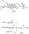
- FIG. 3 schematically shows the structure and operation of the VSV device, here denoted with 25.
- the rotation of blades 29, deviates the flow of air in the compressor 12, thus allowing to avoid an excess of air at low speed that would lead to stall of the compressor 12.
- the electro-hydraulic servo-actuator 26 is electrically controlled by the electronic control unit 20, in particular by the FADEC, which calculates an angular position reference (i.e. the reference value of the beta angle ⁇ ) for the control action, according to a corrected compressor speed Ng r .
- Manufacturers of electro-hydraulic servo-actuators generally provide the nominal response characteristics curves of the actuators in terms of actuator speed versus driving current (where the actuator speed is a function of the driving, or command, current supplied to the actuator).
- the actuator slew-rate i.e. the maximum rate of change per unit of time
- the actuator slew-rate has to be limited, in order not to overcome those limits that could compromise or impair correct operation.
- the same fuel coming from a fuel tank, here not shown, and provided by a fuel pump 30, is supplied to both a fuel metering valve FMV 32, that controls fuel supply to the turbopropeller engine 2, and to the electro-hydraulic servo-actuator 26, that controls the VSV device 25.
- a return path 33 is also provided, for the fuel return flow.
- an excessive speed of the electro-hydraulic servo-actuator 26 may steer too much fuel towards the same actuator, thereby causing a transient pressure drop and possibly impairing the correct operation of the turbopropeller engine 2.
- Figure 5 shows a known control system, denoted with 40, for an electro-hydraulic servo-actuator, here denoted with 41, generally implementing a closed loop control of the position of the actuator 41 based on a reference position Pos ref and a measured position Pos meas (in the example, the measured position Pos meas is provided by a position sensor 42, e.g. an inductive sensor, such as a LVDT - Linear Variable Displacement Transducer).
- a position sensor 42 e.g. an inductive sensor, such as a LVDT - Linear Variable Displacement Transducer
- the control system 40 comprises:
- the control system 40 further comprises a saturation block 46, interposed between the controller 45 and the electro-hydraulic servo-actuator 41, configured to receive the control quantity I c and provide a saturation thereof to maximum and minimum values Max', Min', in case the same control quantity I c overcomes the same maximum and minimum values Max', Min'; the saturation block 46 thus provides a driving quantity I d , in particular a driving current, for the electro-hydraulic servo-actuator 41.
- a saturation block 46 interposed between the controller 45 and the electro-hydraulic servo-actuator 41, configured to receive the control quantity I c and provide a saturation thereof to maximum and minimum values Max', Min', in case the same control quantity I c overcomes the same maximum and minimum values Max', Min'; the saturation block 46 thus provides a driving quantity I d , in particular a driving current, for the electro-hydraulic servo-actuator 41.
- Figure 6 shows the characteristic curve of the electro-hydraulic servo-actuator 41; in particular, the nominal characteristic curve is shown with a solid line, while actual maximum and minimum characteristic curves, e.g. due to actuator ageing and other deterioration effects, are shown with dashed lines.
- the maximum and minimum values Max', Min' of the saturation block 46 are set at values that are lower than the limit values of the driving current, denoted with Max and Min, defined by the nominal characteristic curve of the electro-hydraulic servo-actuator 41 (and corresponding to actuator speed limits, denoted with Speed Max and Speed Min ).
- a drawback of the discussed control system 40 is thus that of not allowing full exploitation of the capability of the electro-hydraulic servo-actuator 41.
- Another known solution to limit the speed of an electro-hydraulic servo-actuator may envisage a mechanical limitation of the control fluid that is supplied to the same electro-hydraulic servo-actuator; however, this solution has a number of disadvantages, for example that of requiring heavy and complex hydraulic mechanisms, having a higher cost and entailing objective constructive difficulties.
- EP 0 867 362 A2 discloses an aircraft servovalve current rate limiter. Aircraft flight path changes commanded by a pilot via the wheel, column and pedal are converted to position sensor signals and passed as the input to primary flight computer. The primary flight computer converts these pilot inputs and the inputs from autopilot into desired surface actuator commands and then transmits them to actuator control electronics. The actuator control electronics also receives a position feedback signal, representative of the position of the aircraft control surface. The actuator control electronics produces a control signal which is fed to the input of an actuator which includes a hydraulic system. The actuator responds to control input signals to drive linkage which then positions the control surface. A rate limiter imposes maximum rate limits to the actuator input signal to thereby reduce peak transient hydraulic fluid pressure in the hydraulic system and corresponding return and pressure lines to specified maximum values.
- the aim of the present solution is to provide an improved control solution for an electro-hydraulic servo-actuator, allowing to overcome the above discussed drawbacks of known control systems.
- an aspect of the present control solution envisages a closed loop control of the actuator slew rate (maximum operating speed), independently of the speed vs current characteristic curve; in particular, this closed loop control for the actuator speed envisages use of the actual actuator speed (evaluated as the derivative of a measured actuator position) in order to limit the rate of change of the actuator driving current, and therefore limit the maximum actuator speed.
- Figure 7 shows a control system, denoted with 50, according to a first embodiment of the present solution, exploiting the above discussed control solution, in order to provide a driving current to an electro-hydraulic servo-actuator, for example to the electro-hydraulic servo-actuator 26 of the VSV device 25 in the turbopropeller engine 2 (see also the above discussion).
- the control system 50 includes, in a manner similar to what discussed before with reference to Figure 5 :
- the maximum and minimum values Max, Min coincide with the limit values defined by the nominal characteristic curve of the electro-hydraulic servo-actuator 26, set by the manufacturer (see again Figure 6 and the associated discussion), and are not set to lower values for safety reasons, as in known control solutions.
- Operation of the saturation block 56 is such as to limit the maximum (absolute) value of the actuator speed, by limiting the maximum (absolute) value for the driving quantity I d .
- this limitation may not be sufficient during transients, when, due to inertia effects, the instantaneous actuator speed may overcome the set maximum limits, notwithstanding the imposed driving current limitations.
- control system 50 therefore further comprises:
- the limitation stage 58 comprises a determination block 59 implementing a look-up table 59a, to determine a maximum rate of change of the actuator current according to the actual actuator speed.
- the look-up table 59a provides at the output a slew rate limit value dI d / dt for limiting the rate of change of the driving current I d , corresponding to the value of the measured actuator speed Speed meas received at the input; the values stored in the look-up table 59a (in particular, the matching between the values of the slew rate limit value dI d / dt and the measured actuator speed Speed meas are determined via experimental results, aimed at determining the slew rate limit values dI d / dt that allow not to overcome the desired actuator speed limits, Speed Max , Speed Min .
- the slew rate limit values dI d / dt and the values of the measured actuator speed Speed meas are linked by a linear inverse relationship, namely when the measured actuator speed Speed meas increases, the slew rate limit value dI d / dt decreases, and vice versa.
- the limitation stage 58 further comprises a dynamic rate limiter 60, coupled to the determination block 59 to receive the determined slew rate limit value dI d / dt, and to the output of the saturation block 56 to receive the driving current I d .
- the dynamic rate limiter 60 is configured to limit the slew rate of the input signal (i.e. the driving current I d ) based on the slew rate limit value dI d / dt , thus providing the rate-limited driving current I d ' for controlling the electro-hydraulic servo-actuator 26.
- the dynamic rate limiter 60 may be implemented in any known manner, here not discussed in detail, as will be clear for a skilled person.
- the slew rate limit value dI d / dt determines the maximum ramp slope of the pattern of the driving current I d vs time; in other words, the rate of change of the driving current I d is not allowed to exceed the slew rate limit value dI d / dt.
- the slew rate limit value dI d / dt is proportional to the actuator acceleration (since the driving current I d is proportional to the actuator speed); accordingly, the dynamic rate limiter 60 operates according to the actuator acceleration providing the rate-limited driving current I d ' so that the actuator speed limits (Speed Max , Speed Min ) are not overcome.
- the acceleration command i.e. the slew rate limit value dI d / dt
- the look-up table 59a is properly tuned to set the maximum rate of change of the actuator speed.
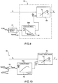
- Figures 9A-9B show simulation results relating to the performance of the discussed control action compared to known control solutions.
- Figure 9A shows the plot of the driving current I d versus time, in the control system 50 according to the present solution (shown in continuous line) and in a known control system (shown in dashed line), where the above discussed control solution is not implemented (e.g. the control system 40 of Figure 5 );
- Figure 9A clearly shows the rate-limitation of the driving current I d envisaged by the present control solution.
- Figure 9B shows the plot of the actuator speed versus time, again showing with a continuous line the plot according to the present control solution and with a dashed line the plot according to the known control solution.
- Figure 9B also shows the actuator speed limits, Speed Max , Speed Min .
- Figure 9B clearly shows that the present control solution allows to avoid the actuator speed to overcome the actuator speed limits, Speed Max , Speed Min , contrary to the known control solution.
- the present solution provides an effective system to control operation of an electro-hydraulic servo-actuator 26, properly limiting the maximum speed of the same actuator, i.e. the actuator slew rate.
- the actuator speed is limited dynamically and independently of the nominal characteristic curve (speed vs driving current) of the electro-hydraulic servo-actuator.
- the present control system 50 allows to fully exploit the capability of the electro-hydraulic servo-actuator 26; contrary to known mechanical control solutions, the present control system 50 does not require complex and expensive control mechanisms.
- the same limitation stage 58 may comprise a second adder block, here denoted with 64, receiving at a first (positive, or summation) input the actuator speed limit Speed Max (the absolute value thereof), and at a second (negative, or subtraction) input the measured actuator speed Speed meas , and providing at the output a speed difference e speed , as a function of the subtraction between the actuator speed limit Speed Max and the measured actuator speed Speed meas .
- a second adder block here denoted with 64, receiving at a first (positive, or summation) input the actuator speed limit Speed Max (the absolute value thereof), and at a second (negative, or subtraction) input the measured actuator speed Speed meas , and providing at the output a speed difference e speed , as a function of the subtraction between the actuator speed limit Speed Max and the measured actuator speed Speed meas .
- the look-up table 59a receives at the input the above speed difference e speed , and provides the slew rate limit value dI d / dt based on the same speed difference e speed .
- the slew rate limit values dI d / dt and the values of the speed difference e speed are linked by a linear direct relationship, at least up to a given value of the same speed difference e speed , namely when the speed difference e speed increases/decreases, the slew rate limit value dI d / dt correspondingly increases/decreases.
- the slew rate limit values dI d / dt are higher; as the measured actuator speed Speed meas approaches the actuator speed limit Speed Max , the slew rate limit values dI d / dt is decreased, so as to limit the actuator acceleration.
- the slew rate limit value dI d / dt is supplied to the dynamic rate limiter 60, which also in this case is configured to limit the slew rate of the driving current I d based on the slew rate limit value dI d / dt , to provide the rate-limited driving current I d ' for controlling the electro-hydraulic servo-actuator 26.
- control system 50 may advantageously be employed for controlling any electro-hydraulic servo-actuator.
- control system 50 is advantageous every time a first valve, e.g. a variable geometry (VG) valve, and a second, different, valve are to be controlled using a same control fluid, to limit the actuator speed of the first valve in order to avoid steering too much control fluid towards the same first valve and away from the second valve.
- VG variable geometry
Landscapes
- Engineering & Computer Science (AREA)
- Aviation & Aerospace Engineering (AREA)
- Physics & Mathematics (AREA)
- Fluid Mechanics (AREA)
- Mechanical Engineering (AREA)
- General Engineering & Computer Science (AREA)
- General Physics & Mathematics (AREA)
- Automation & Control Theory (AREA)
- Fluid-Pressure Circuits (AREA)
- Servomotors (AREA)
- Supercharger (AREA)
Claims (13)
- Système de commande (50) pour un servomoteur électro-hydraulique (26), le système de commande (50) comprenant :un capteur de position (52), configuré pour fournir une position mesurée (Posmeas) du servomoteur électro-hydraulique (26) ;une commande (55), configurée pour générer un courant de commande (Ic), conçu pour commander l'actionnement du servomoteur électro-hydraulique (26), en mettant en œuvre une boucle de commande de position basée sur une erreur de position (ep), l'erreur de position (ep) étant une différence entre une position de référence (Posref) et la position mesurée (Posmeas) du servomoteur électro-hydraulique (26) ; etun étage de limitation (58), couplé à la commande (55) et configuré pour fournir une limitation de la vitesse d'actionnement du servomoteur électro-hydraulique (26),dans lequel l'étage de limitation (58) est configuré pour limiter un taux de variation d'un courant d'entraînement (Id) à fournir au servomoteur électro-hydraulique (26), afin de limiter la vitesse d'actionnement ;caractérisé en ce que l'étage de limitation (58) est configuré pour mettre en œuvre une boucle de commande fermée de la vitesse d'actionnement en fonction d'une vitesse d'actionnement mesurée (Speedmeas), pour fournir un courant d'entraînement (Id') à vitesse limitée pour commander le servomoteur électro-hydraulique (26)comprenant en outre un bloc dérivatif (57), couplé au capteur de position (52) pour recevoir la position mesurée (Posmeas) et configuré pour déterminer la vitesse d'actionnement mesurée (Speedmeas) comme la dérivée de la position mesurée (Posmeas).
- Système de commande selon la revendication 1, dans lequel l'étage de limitation (58) comprend :un bloc de détermination (59), configuré pour recevoir la vitesse d'actionnement mesurée (Speedmeas) et pour déterminer, en fonction de la vitesse d'actionnement mesurée (Speedmeas), une valeur limite de vitesse de balayage (dld /dt) pour limiter le taux de variation du courant d'entraînement (Id) ; etun limiteur de taux dynamique (60), couplé au bloc de détermination (59) pour recevoir la valeur limite de vitesse de balayage (dld /dt) et configuré pour limiter la vitesse de balayage du courant d'entraînement (Id) en fonction de la valeur limite de vitesse de balayage (dld /dt), fournissant ainsi le courant d'entraînement à vitesse limitée (Id') pour commander le servomoteur électro-hydraulique (26).
- Système de commande selon la revendication 2, dans lequel la valeur limite de vitesse de balayage (dld /dt) est conçue pour déterminer une pente de rampe maximum de la courbe du courant d'entraînement (Id) en fonction du temps.
- Système de commande selon la revendication 2 ou 3, dans lequel le bloc de détermination (59) est configuré pour mettre en œuvre un tableau de consultation (59a), fournissant à la sortie la valeur limite de vitesse de balayage (dld /dt) correspondant à une valeur d'entrée de la vitesse d'actionnement mesurée (Speedmeas).
- Système de commande selon la revendication 4, dans lequel dans lequel le tableau de consultation (59a) stocke des correspondances entre les valeurs limites de vitesse de balayage (dld /dt) et les vitesses d'actionneur mesurées (Speedmeas) déterminées par des résultats expérimentaux.
- Système de commande selon la revendication 4 ou 5, dans lequel les valeurs limites de vitesse de balayage (dld /dt) et les valeurs de la vitesse d'actionnement mesurée (Speedmeas) sont liées par une relation inverse linéaire.
- Système de commande selon l'une quelconque des revendications 2-6, dans lequel la valeur limite de vitesse de balayage (dld /dt) est proportionnelle à une valeur d'accélération d'actionneur, et le limiteur de vitesse dynamique (60) est configuré pour fournir le courant d'entraînement à vitesse limitée (Id') en fonction de la valeur d'accélération d'actionneur.
- Système de commande selon la revendication 2 ou 3, dans lequel le bloc de détermination (59) est configuré pour mettre en œuvre un tableau de consultation (59a), fournissant à la sortie une valeur limite de vitesse de balayage (dld /dt) correspondant à la valeur d'une différence de vitesse (espeed), entre une limite de vitesse d'actionnement (Speedmax) et la vitesse d'actionnement mesurée (Speedmeas).
- Système de commande selon l'une quelconque des revendications précédentes, dans lequel le courant d'entraînement (Id) est une fonction du courant de commande (Ic).
- Système de commande selon la revendication 9, comprenant en outre un bloc de saturation (56), intercalé entre la commande (55) et le servomoteur électro-hydraulique (26), configuré pour recevoir le courant de commande (Ic) depuis la commande (55), et fournir une saturation de celle-ci à des valeurs maximum et minimum (Max, Min), dans le cas où le courant de commande (Ic) dépasse les valeurs maximum et minimum (Max, Min), fournissant ainsi le courant d'entraînement (Id) à l'étage de limitation (58).
- Agencement de valves, comprenant une première (25) et une seconde (32) valve commandées par un même fluide de commande ; l'agencement de valves comprenant le système de commande (50) selon l'une quelconque des revendications précédentes, pour entraîner un servomoteur électro-hydraulique (26) conçu pour commander l'actionnement de la première valve (25), afin de limiter la vitesse d'actionnement du servomoteur électro-hydraulique (26).
- Turbopropulseur (2) pour un aéronef (2), comprenant une turbine à gaz (11) et une ensemble propulseur (3) couplé à la turbine à gaz (11), la turbine à gaz (11) comportant un compresseur (12) couplé à une entrée d'air (13) ; caractérisé en ce qu'il comprend l'agencement de valves selon la revendication 11 ; dans lequel la première valve (25) est couplée au compresseur (12) pour fractionner le flux d'air vers le compresseur (12), et la seconde valve (26) est une valve de dosage de carburant (32) configurée pour commander l'alimentation en carburant vers le turbopropulseur (2), le fluide de commande étant du carburant venant d'un réservoir de carburant et fourni par une pompe à carburant (30).
- Procédé de commande pour un servomoteur électro-hydraulique (26), comprenant :de fournir, par un capteur de position (52), une position mesurée (Posmeas) du servomoteur électro-hydraulique (26) ; de générer un courant de commande (Ic) pour commander l'actionnement du servomoteur électro-hydraulique (26), de mettre en œuvre une boucle de commande de position basée sur une erreur de position (ep), l'erreur de position (ep) étant une différence entre une position de référence (Posref) et la position mesurée (Posmeas) du servomoteur électro-hydraulique (26) ; etde réaliser une limitation de la vitesse d'actionnement du servomoteur électro-hydraulique (26),dans lequel réaliser une limitation inclut de limiter une vitesse de variation d'un courant d'entraînement (Id) à fournir au servomoteur électro-hydraulique (26),caractérisé en ce que réaliser une limitation comprend de mettre en œuvre une boucle de commande fermée de la vitesse d'actionnement en fonction d'une vitesse d'actionnement mesurée (Speedmeas), pour fournir un courant d'entraînement (Id') à vitesse limitée pour commander le servomoteur électro-hydraulique (26)comprenant en outre de déterminer la vitesse d'actionnement mesurée (Speedmeas) comme la dérivée de la position mesurée (Posmeas), par un bloc dérivatif (57) couplé au capteur de position (52).
Priority Applications (4)
| Application Number | Priority Date | Filing Date | Title |
|---|---|---|---|
| EP18425049.6A EP3587254B1 (fr) | 2018-06-28 | 2018-06-28 | Système et procédé de commande de servo-moteur électro-hydraulique, en particulier d'un moteur de turbopropulseur |
| CN201980043075.9A CN112334385B (zh) | 2018-06-28 | 2019-06-28 | 用于电液伺服致动器的控制系统和方法 |
| US16/973,268 US11332234B2 (en) | 2018-06-28 | 2019-06-28 | Control system and method for an electro-hydraulic servo-actuator, in particular of a turbopropeller engine |
| PCT/EP2019/067495 WO2020002692A1 (fr) | 2018-06-28 | 2019-06-28 | Système de commande et procédé pour servo-actionneur électro-hydraulique, en particulier d'un moteur à turbopropulseur |
Applications Claiming Priority (1)
| Application Number | Priority Date | Filing Date | Title |
|---|---|---|---|
| EP18425049.6A EP3587254B1 (fr) | 2018-06-28 | 2018-06-28 | Système et procédé de commande de servo-moteur électro-hydraulique, en particulier d'un moteur de turbopropulseur |
Publications (2)
| Publication Number | Publication Date |
|---|---|
| EP3587254A1 EP3587254A1 (fr) | 2020-01-01 |
| EP3587254B1 true EP3587254B1 (fr) | 2021-11-17 |
Family
ID=63244535
Family Applications (1)
| Application Number | Title | Priority Date | Filing Date |
|---|---|---|---|
| EP18425049.6A Active EP3587254B1 (fr) | 2018-06-28 | 2018-06-28 | Système et procédé de commande de servo-moteur électro-hydraulique, en particulier d'un moteur de turbopropulseur |
Country Status (4)
| Country | Link |
|---|---|
| US (1) | US11332234B2 (fr) |
| EP (1) | EP3587254B1 (fr) |
| CN (1) | CN112334385B (fr) |
| WO (1) | WO2020002692A1 (fr) |
Families Citing this family (7)
| Publication number | Priority date | Publication date | Assignee | Title |
|---|---|---|---|---|
| EP3587254B1 (fr) * | 2018-06-28 | 2021-11-17 | GE Avio S.r.l. | Système et procédé de commande de servo-moteur électro-hydraulique, en particulier d'un moteur de turbopropulseur |
| US12446578B2 (en) | 2020-02-10 | 2025-10-21 | Virox Technologies Inc. | Antimicrobial compositions containing peroxyphthalic acid and/or salt thereof |
| GB2595910A (en) * | 2020-06-11 | 2021-12-15 | Mbda Uk Ltd | Servo power limiting |
| DE102021128424B3 (de) | 2021-11-01 | 2023-03-02 | Samson Aktiengesellschaft | Verfahren und Vorrichtungen zum Regeln einer Regelstrecke mit fluidischem Antrieb |
| DE102022100223B3 (de) | 2022-01-05 | 2023-05-04 | Samson Aktiengesellschaft | Verfahren und Vorrichtungen zum Regeln einer hoch dynamischen Regelstrecke mit fluidischen Antrieb mithilfe eines Ratenbegrenzers |
| US11920522B2 (en) | 2022-03-07 | 2024-03-05 | Ge Avio S.R.L. | Method and apparatus for controlling fuel flow into an aircraft engine |
| CN119439699A (zh) * | 2025-01-08 | 2025-02-14 | 大连理工大学 | 基于模糊逻辑的自适应pid飞机电液伺服系统控制方法 |
Family Cites Families (9)
| Publication number | Priority date | Publication date | Assignee | Title |
|---|---|---|---|---|
| US5740782A (en) * | 1996-05-20 | 1998-04-21 | Lowi, Jr.; Alvin | Positive-displacement-metering, electro-hydraulic fuel injection system |
| US6003811A (en) | 1997-03-24 | 1999-12-21 | The Boeing Company | Aircraft servovalve current rate limiter |
| US6137187A (en) | 1997-08-08 | 2000-10-24 | Zond Energy Systems, Inc. | Variable speed wind turbine generator |
| CN101376433B (zh) * | 2008-10-10 | 2010-11-10 | 南京航空航天大学 | 直升机旋翼操纵方法及系统 |
| FR2946316A1 (fr) * | 2009-06-04 | 2010-12-10 | Eurocopter France | Procede de controle en lacet d'un helicoptere hybride,et helicoptere hybride muni d'un dispositif de commande en lacet apte a mettre en oeuvre ledit procede |
| WO2011153069A1 (fr) * | 2010-06-01 | 2011-12-08 | Cummins Intellectual Properties, Inc. | Système de commande pour moteurs bi-combustible |
| US9828109B2 (en) * | 2014-07-23 | 2017-11-28 | Pratt & Whitney Canada Corp. | Apparatus and methods for powering an electrical device associated with an aircraft rotor |
| EP3587254B1 (fr) * | 2018-06-28 | 2021-11-17 | GE Avio S.r.l. | Système et procédé de commande de servo-moteur électro-hydraulique, en particulier d'un moteur de turbopropulseur |
| JP2021099122A (ja) * | 2019-12-20 | 2021-07-01 | 川崎重工業株式会社 | 静油圧無段変速システム |
-
2018
- 2018-06-28 EP EP18425049.6A patent/EP3587254B1/fr active Active
-
2019
- 2019-06-28 WO PCT/EP2019/067495 patent/WO2020002692A1/fr not_active Ceased
- 2019-06-28 CN CN201980043075.9A patent/CN112334385B/zh active Active
- 2019-06-28 US US16/973,268 patent/US11332234B2/en active Active
Non-Patent Citations (1)
| Title |
|---|
| None * |
Also Published As
| Publication number | Publication date |
|---|---|
| US20210362838A1 (en) | 2021-11-25 |
| EP3587254A1 (fr) | 2020-01-01 |
| CN112334385A (zh) | 2021-02-05 |
| US11332234B2 (en) | 2022-05-17 |
| WO2020002692A1 (fr) | 2020-01-02 |
| CN112334385B (zh) | 2024-05-03 |
Similar Documents
| Publication | Publication Date | Title |
|---|---|---|
| US11332234B2 (en) | Control system and method for an electro-hydraulic servo-actuator, in particular of a turbopropeller engine | |
| EP3543112B1 (fr) | Système et procédé de commande combinée de vitesse et de pas d'hélice pour un moteur turbopropulseur | |
| US10773816B2 (en) | Single lever turboprop control systems and methods utilizing torque-based and power-based scheduling | |
| EP3055204B1 (fr) | Procédé et appareil permettant de commander un turbopropulseur | |
| US8291886B2 (en) | Actuator flow compensated direct metering fuel control system and method | |
| US3930366A (en) | Helicopter power plant control | |
| US5299911A (en) | Electric pitch control apparatus for variable-pitch propeller | |
| US20210009252A1 (en) | System and method for propeller response enhancement during transition from ground to flight configuration for a turbopropeller engine | |
| EP4296492A1 (fr) | Distribution de carburant à double pompe pour un aéronef | |
| US5284418A (en) | Electric pitch control apparatus for variable pitch propeller capable of controlling the pitch angle based instantaneous operational conditions of the propeller | |
| US20110185698A1 (en) | Free gas turbine with constant temperature-corrected gas generator speed | |
| EP2341230A2 (fr) | Système de mesure de carburant à pompe de mesure servo électrique | |
| EP3594110B1 (fr) | Système et procédé de mise en drapeau d'une hélice d'avion | |
| EP2434130B1 (fr) | Soupape de démarreur de turbine | |
| EP3543504B1 (fr) | Système et procédé de commande de limitation de dépassement de vitesse d'hélice dans un moteur de turbopropulseur | |
| US20200232395A1 (en) | Method and system for operating a gas turbine engine coupled to an aircraft propeller | |
| WO1993006353A1 (fr) | Commande de regulation de vitesse d'helice pour moteurs a turbopropulseur________________________________________________________ | |
| EP4585508A1 (fr) | Régulation de vitesse basée sur un modèle pour hélice à pas variable | |
| EP4585509A1 (fr) | Procédé et système de commande d'une hélice à pas variable avec compensation de fuite d'huile | |
| CA3261389A1 (fr) | Régulation de vitesse à base de modèle pour une hélice à pas variable | |
| WO2019243371A1 (fr) | Système et procédé de commande pour un moteur à turbopropulseur fondés sur une détection de température d'entrée | |
| CA3261437A1 (fr) | Méthode et système pour contrôler une hélice à pas variable avec une compensation pour les fuites d’huile | |
| EP4332362A1 (fr) | Systèmes de carburant entraînés par moteur hydraulique à vitesse variable | |
| EP2489859A1 (fr) | Turbine à gaz libre avec vitesse de rotation du générateur au gaz corrigée à température constante |
Legal Events
| Date | Code | Title | Description |
|---|---|---|---|
| PUAI | Public reference made under article 153(3) epc to a published international application that has entered the european phase |
Free format text: ORIGINAL CODE: 0009012 |
|
| STAA | Information on the status of an ep patent application or granted ep patent |
Free format text: STATUS: THE APPLICATION HAS BEEN PUBLISHED |
|
| AK | Designated contracting states |
Kind code of ref document: A1 Designated state(s): AL AT BE BG CH CY CZ DE DK EE ES FI FR GB GR HR HU IE IS IT LI LT LU LV MC MK MT NL NO PL PT RO RS SE SI SK SM TR |
|
| AX | Request for extension of the european patent |
Extension state: BA ME |
|
| STAA | Information on the status of an ep patent application or granted ep patent |
Free format text: STATUS: REQUEST FOR EXAMINATION WAS MADE |
|
| 17P | Request for examination filed |
Effective date: 20200701 |
|
| RBV | Designated contracting states (corrected) |
Designated state(s): AL AT BE BG CH CY CZ DE DK EE ES FI FR GB GR HR HU IE IS IT LI LT LU LV MC MK MT NL NO PL PT RO RS SE SI SK SM TR |
|
| STAA | Information on the status of an ep patent application or granted ep patent |
Free format text: STATUS: EXAMINATION IS IN PROGRESS |
|
| 17Q | First examination report despatched |
Effective date: 20201119 |
|
| GRAP | Despatch of communication of intention to grant a patent |
Free format text: ORIGINAL CODE: EPIDOSNIGR1 |
|
| STAA | Information on the status of an ep patent application or granted ep patent |
Free format text: STATUS: GRANT OF PATENT IS INTENDED |
|
| INTG | Intention to grant announced |
Effective date: 20210615 |
|
| GRAS | Grant fee paid |
Free format text: ORIGINAL CODE: EPIDOSNIGR3 |
|
| GRAA | (expected) grant |
Free format text: ORIGINAL CODE: 0009210 |
|
| STAA | Information on the status of an ep patent application or granted ep patent |
Free format text: STATUS: THE PATENT HAS BEEN GRANTED |
|
| AK | Designated contracting states |
Kind code of ref document: B1 Designated state(s): AL AT BE BG CH CY CZ DE DK EE ES FI FR GB GR HR HU IE IS IT LI LT LU LV MC MK MT NL NO PL PT RO RS SE SI SK SM TR |
|
| REG | Reference to a national code |
Ref country code: GB Ref legal event code: FG4D |
|
| REG | Reference to a national code |
Ref country code: DE Ref legal event code: R096 Ref document number: 602018026766 Country of ref document: DE |
|
| REG | Reference to a national code |
Ref country code: IE Ref legal event code: FG4D |
|
| REG | Reference to a national code |
Ref country code: AT Ref legal event code: REF Ref document number: 1447847 Country of ref document: AT Kind code of ref document: T Effective date: 20211215 |
|
| REG | Reference to a national code |
Ref country code: LT Ref legal event code: MG9D |
|
| REG | Reference to a national code |
Ref country code: NL Ref legal event code: MP Effective date: 20211117 |
|
| REG | Reference to a national code |
Ref country code: AT Ref legal event code: MK05 Ref document number: 1447847 Country of ref document: AT Kind code of ref document: T Effective date: 20211117 |
|
| PG25 | Lapsed in a contracting state [announced via postgrant information from national office to epo] |
Ref country code: RS Free format text: LAPSE BECAUSE OF FAILURE TO SUBMIT A TRANSLATION OF THE DESCRIPTION OR TO PAY THE FEE WITHIN THE PRESCRIBED TIME-LIMIT Effective date: 20211117 Ref country code: LT Free format text: LAPSE BECAUSE OF FAILURE TO SUBMIT A TRANSLATION OF THE DESCRIPTION OR TO PAY THE FEE WITHIN THE PRESCRIBED TIME-LIMIT Effective date: 20211117 Ref country code: FI Free format text: LAPSE BECAUSE OF FAILURE TO SUBMIT A TRANSLATION OF THE DESCRIPTION OR TO PAY THE FEE WITHIN THE PRESCRIBED TIME-LIMIT Effective date: 20211117 Ref country code: BG Free format text: LAPSE BECAUSE OF FAILURE TO SUBMIT A TRANSLATION OF THE DESCRIPTION OR TO PAY THE FEE WITHIN THE PRESCRIBED TIME-LIMIT Effective date: 20220217 Ref country code: AT Free format text: LAPSE BECAUSE OF FAILURE TO SUBMIT A TRANSLATION OF THE DESCRIPTION OR TO PAY THE FEE WITHIN THE PRESCRIBED TIME-LIMIT Effective date: 20211117 |
|
| PG25 | Lapsed in a contracting state [announced via postgrant information from national office to epo] |
Ref country code: IS Free format text: LAPSE BECAUSE OF FAILURE TO SUBMIT A TRANSLATION OF THE DESCRIPTION OR TO PAY THE FEE WITHIN THE PRESCRIBED TIME-LIMIT Effective date: 20220317 Ref country code: SE Free format text: LAPSE BECAUSE OF FAILURE TO SUBMIT A TRANSLATION OF THE DESCRIPTION OR TO PAY THE FEE WITHIN THE PRESCRIBED TIME-LIMIT Effective date: 20211117 Ref country code: PT Free format text: LAPSE BECAUSE OF FAILURE TO SUBMIT A TRANSLATION OF THE DESCRIPTION OR TO PAY THE FEE WITHIN THE PRESCRIBED TIME-LIMIT Effective date: 20220317 Ref country code: PL Free format text: LAPSE BECAUSE OF FAILURE TO SUBMIT A TRANSLATION OF THE DESCRIPTION OR TO PAY THE FEE WITHIN THE PRESCRIBED TIME-LIMIT Effective date: 20211117 Ref country code: NO Free format text: LAPSE BECAUSE OF FAILURE TO SUBMIT A TRANSLATION OF THE DESCRIPTION OR TO PAY THE FEE WITHIN THE PRESCRIBED TIME-LIMIT Effective date: 20220217 Ref country code: NL Free format text: LAPSE BECAUSE OF FAILURE TO SUBMIT A TRANSLATION OF THE DESCRIPTION OR TO PAY THE FEE WITHIN THE PRESCRIBED TIME-LIMIT Effective date: 20211117 Ref country code: LV Free format text: LAPSE BECAUSE OF FAILURE TO SUBMIT A TRANSLATION OF THE DESCRIPTION OR TO PAY THE FEE WITHIN THE PRESCRIBED TIME-LIMIT Effective date: 20211117 Ref country code: HR Free format text: LAPSE BECAUSE OF FAILURE TO SUBMIT A TRANSLATION OF THE DESCRIPTION OR TO PAY THE FEE WITHIN THE PRESCRIBED TIME-LIMIT Effective date: 20211117 Ref country code: GR Free format text: LAPSE BECAUSE OF FAILURE TO SUBMIT A TRANSLATION OF THE DESCRIPTION OR TO PAY THE FEE WITHIN THE PRESCRIBED TIME-LIMIT Effective date: 20220218 Ref country code: ES Free format text: LAPSE BECAUSE OF FAILURE TO SUBMIT A TRANSLATION OF THE DESCRIPTION OR TO PAY THE FEE WITHIN THE PRESCRIBED TIME-LIMIT Effective date: 20211117 |
|
| PG25 | Lapsed in a contracting state [announced via postgrant information from national office to epo] |
Ref country code: SM Free format text: LAPSE BECAUSE OF FAILURE TO SUBMIT A TRANSLATION OF THE DESCRIPTION OR TO PAY THE FEE WITHIN THE PRESCRIBED TIME-LIMIT Effective date: 20211117 Ref country code: SK Free format text: LAPSE BECAUSE OF FAILURE TO SUBMIT A TRANSLATION OF THE DESCRIPTION OR TO PAY THE FEE WITHIN THE PRESCRIBED TIME-LIMIT Effective date: 20211117 Ref country code: RO Free format text: LAPSE BECAUSE OF FAILURE TO SUBMIT A TRANSLATION OF THE DESCRIPTION OR TO PAY THE FEE WITHIN THE PRESCRIBED TIME-LIMIT Effective date: 20211117 Ref country code: EE Free format text: LAPSE BECAUSE OF FAILURE TO SUBMIT A TRANSLATION OF THE DESCRIPTION OR TO PAY THE FEE WITHIN THE PRESCRIBED TIME-LIMIT Effective date: 20211117 Ref country code: DK Free format text: LAPSE BECAUSE OF FAILURE TO SUBMIT A TRANSLATION OF THE DESCRIPTION OR TO PAY THE FEE WITHIN THE PRESCRIBED TIME-LIMIT Effective date: 20211117 Ref country code: CZ Free format text: LAPSE BECAUSE OF FAILURE TO SUBMIT A TRANSLATION OF THE DESCRIPTION OR TO PAY THE FEE WITHIN THE PRESCRIBED TIME-LIMIT Effective date: 20211117 |
|
| REG | Reference to a national code |
Ref country code: DE Ref legal event code: R097 Ref document number: 602018026766 Country of ref document: DE |
|
| PLBE | No opposition filed within time limit |
Free format text: ORIGINAL CODE: 0009261 |
|
| STAA | Information on the status of an ep patent application or granted ep patent |
Free format text: STATUS: NO OPPOSITION FILED WITHIN TIME LIMIT |
|
| 26N | No opposition filed |
Effective date: 20220818 |
|
| PG25 | Lapsed in a contracting state [announced via postgrant information from national office to epo] |
Ref country code: AL Free format text: LAPSE BECAUSE OF FAILURE TO SUBMIT A TRANSLATION OF THE DESCRIPTION OR TO PAY THE FEE WITHIN THE PRESCRIBED TIME-LIMIT Effective date: 20211117 |
|
| PG25 | Lapsed in a contracting state [announced via postgrant information from national office to epo] |
Ref country code: SI Free format text: LAPSE BECAUSE OF FAILURE TO SUBMIT A TRANSLATION OF THE DESCRIPTION OR TO PAY THE FEE WITHIN THE PRESCRIBED TIME-LIMIT Effective date: 20211117 |
|
| PG25 | Lapsed in a contracting state [announced via postgrant information from national office to epo] |
Ref country code: MC Free format text: LAPSE BECAUSE OF FAILURE TO SUBMIT A TRANSLATION OF THE DESCRIPTION OR TO PAY THE FEE WITHIN THE PRESCRIBED TIME-LIMIT Effective date: 20211117 |
|
| REG | Reference to a national code |
Ref country code: CH Ref legal event code: PL |
|
| REG | Reference to a national code |
Ref country code: BE Ref legal event code: MM Effective date: 20220630 |
|
| PG25 | Lapsed in a contracting state [announced via postgrant information from national office to epo] |
Ref country code: LU Free format text: LAPSE BECAUSE OF NON-PAYMENT OF DUE FEES Effective date: 20220628 Ref country code: LI Free format text: LAPSE BECAUSE OF NON-PAYMENT OF DUE FEES Effective date: 20220630 Ref country code: IE Free format text: LAPSE BECAUSE OF NON-PAYMENT OF DUE FEES Effective date: 20220628 Ref country code: CH Free format text: LAPSE BECAUSE OF NON-PAYMENT OF DUE FEES Effective date: 20220630 |
|
| PG25 | Lapsed in a contracting state [announced via postgrant information from national office to epo] |
Ref country code: IT Free format text: LAPSE BECAUSE OF FAILURE TO SUBMIT A TRANSLATION OF THE DESCRIPTION OR TO PAY THE FEE WITHIN THE PRESCRIBED TIME-LIMIT Effective date: 20211117 Ref country code: BE Free format text: LAPSE BECAUSE OF NON-PAYMENT OF DUE FEES Effective date: 20220630 |
|
| P01 | Opt-out of the competence of the unified patent court (upc) registered |
Effective date: 20230411 |
|
| PG25 | Lapsed in a contracting state [announced via postgrant information from national office to epo] |
Ref country code: MK Free format text: LAPSE BECAUSE OF FAILURE TO SUBMIT A TRANSLATION OF THE DESCRIPTION OR TO PAY THE FEE WITHIN THE PRESCRIBED TIME-LIMIT Effective date: 20211117 Ref country code: CY Free format text: LAPSE BECAUSE OF FAILURE TO SUBMIT A TRANSLATION OF THE DESCRIPTION OR TO PAY THE FEE WITHIN THE PRESCRIBED TIME-LIMIT Effective date: 20211117 |
|
| PG25 | Lapsed in a contracting state [announced via postgrant information from national office to epo] |
Ref country code: HU Free format text: LAPSE BECAUSE OF FAILURE TO SUBMIT A TRANSLATION OF THE DESCRIPTION OR TO PAY THE FEE WITHIN THE PRESCRIBED TIME-LIMIT; INVALID AB INITIO Effective date: 20180628 |
|
| PG25 | Lapsed in a contracting state [announced via postgrant information from national office to epo] |
Ref country code: MT Free format text: LAPSE BECAUSE OF FAILURE TO SUBMIT A TRANSLATION OF THE DESCRIPTION OR TO PAY THE FEE WITHIN THE PRESCRIBED TIME-LIMIT Effective date: 20211117 |
|
| PGFP | Annual fee paid to national office [announced via postgrant information from national office to epo] |
Ref country code: DE Payment date: 20250520 Year of fee payment: 8 |
|
| PGFP | Annual fee paid to national office [announced via postgrant information from national office to epo] |
Ref country code: GB Payment date: 20250520 Year of fee payment: 8 |
|
| PGFP | Annual fee paid to national office [announced via postgrant information from national office to epo] |
Ref country code: FR Payment date: 20250520 Year of fee payment: 8 |
|
| PG25 | Lapsed in a contracting state [announced via postgrant information from national office to epo] |
Ref country code: TR Free format text: LAPSE BECAUSE OF FAILURE TO SUBMIT A TRANSLATION OF THE DESCRIPTION OR TO PAY THE FEE WITHIN THE PRESCRIBED TIME-LIMIT Effective date: 20211117 |