EP3587328B1 - Déclencheur électromagnétique de sécurité - Google Patents
Déclencheur électromagnétique de sécurité Download PDFInfo
- Publication number
- EP3587328B1 EP3587328B1 EP19167273.2A EP19167273A EP3587328B1 EP 3587328 B1 EP3587328 B1 EP 3587328B1 EP 19167273 A EP19167273 A EP 19167273A EP 3587328 B1 EP3587328 B1 EP 3587328B1
- Authority
- EP
- European Patent Office
- Prior art keywords
- electromagnetic component
- electromagnetic
- move
- retention apparatus
- brake
- Prior art date
- Legal status (The legal status is an assumption and is not a legal conclusion. Google has not performed a legal analysis and makes no representation as to the accuracy of the status listed.)
- Active
Links
Images




Classifications
-
- B—PERFORMING OPERATIONS; TRANSPORTING
- B66—HOISTING; LIFTING; HAULING
- B66B—ELEVATORS; ESCALATORS OR MOVING WALKWAYS
- B66B5/00—Applications of checking, fault-correcting, or safety devices in elevators
- B66B5/02—Applications of checking, fault-correcting, or safety devices in elevators responsive to abnormal operating conditions
- B66B5/16—Braking or catch devices operating between cars, cages, or skips and fixed guide elements or surfaces in hoistway or well
- B66B5/18—Braking or catch devices operating between cars, cages, or skips and fixed guide elements or surfaces in hoistway or well and applying frictional retarding forces
- B66B5/22—Braking or catch devices operating between cars, cages, or skips and fixed guide elements or surfaces in hoistway or well and applying frictional retarding forces by means of linearly-movable wedges
-
- B—PERFORMING OPERATIONS; TRANSPORTING
- B66—HOISTING; LIFTING; HAULING
- B66B—ELEVATORS; ESCALATORS OR MOVING WALKWAYS
- B66B5/00—Applications of checking, fault-correcting, or safety devices in elevators
- B66B5/02—Applications of checking, fault-correcting, or safety devices in elevators responsive to abnormal operating conditions
- B66B5/04—Applications of checking, fault-correcting, or safety devices in elevators responsive to abnormal operating conditions for detecting excessive speed
- B66B5/044—Mechanical overspeed governors
-
- B—PERFORMING OPERATIONS; TRANSPORTING
- B66—HOISTING; LIFTING; HAULING
- B66B—ELEVATORS; ESCALATORS OR MOVING WALKWAYS
- B66B5/00—Applications of checking, fault-correcting, or safety devices in elevators
- B66B5/02—Applications of checking, fault-correcting, or safety devices in elevators responsive to abnormal operating conditions
- B66B5/16—Braking or catch devices operating between cars, cages, or skips and fixed guide elements or surfaces in hoistway or well
- B66B5/18—Braking or catch devices operating between cars, cages, or skips and fixed guide elements or surfaces in hoistway or well and applying frictional retarding forces
Definitions
- the present disclosure is generally related to braking and/or safety systems and, more specifically, an electromagnetic safety trigger.
- Some machines such as an elevator system, include a safety system to stop the machine when it rotates or travels at excessive speeds in response to an inoperative component.
- a traditional safety system includes a significant number of components that are required to effectively operate the system. These additional components increase installation time and costs. There is therefore a need for a safety system that reduces the number of components and is cost effective.
- WO2017/087978 describes an electronic safety actuator for an elevator system including a safety brake coupled to a magnetic brake by a rod, in which engagement of the magnetic brake causes engagement of the safety brake.
- US 2011/0088983 describes an elevator braking device in which bringing a first braking surface into contact with a guide rail causes a second braking mechanism to engage with the guide rail.
- selectively operable braking device for an elevator system is provided according to claim 1.
- the retention apparatus may further comprise a housing wall, wherein the biasing member is disposed between the housing wall and the electromagnetic component, wherein the biasing component is operative to apply the force to the electromagnetic component in the direction parallel to the actuation axis.
- the retention apparatus may further comprise: a motor; and a threaded shaft operably coupled to the motor for rotation thereof by the motor; wherein the threaded shaft is further threadingly coupled to the electromagnetic component such that rotation of the threaded shaft by the motor causes the electromagnetic component to move in the direction parallel to the actuation axis.
- the selectively operable braking device further includes a safety controller in electrical communication with the electromagnetic component, the safety controller configured to send a trigger signal and the resetting signal, wherein the electromagnetic component is configured to move the magnetic brake to the rail-engaging position upon receipt of the trigger signal.
- the electromagnetic component is configured to hold the magnetic brake in the rail-non-engaging position.
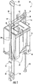
- FIG. 1 shows an elevator system, generally indicated at 10.
- the elevator system 10 includes cables 12, a car frame 14, a car 16, roller guides 18, guide rails 20, a governor 22, safeties 24, linkages 26, levers 28, and lift rods 30.
- Governor 22 includes a governor sheave 32, rope loop 34, and a tensioning sheave 36.
- Cables 12 are connected to car frame 14 and a counterweight (not shown in FIG. 1 ) inside a hoistway.
- Car 16, which is attached to car frame 14, moves up and down the hoistway by force transmitted through cables 12 to car frame 14 by an elevator drive (not shown) commonly located in a machine room at the top of the hoistway.
- Roller guides 18 are attached to car frame 14 to guide the car 16 up and down the hoistway along guide rail 20.
- governor sheave 32 is mounted at an upper end of the hoistway.
- Rope loop 34 is wrapped partially around governor sheave 32 and partially around tensioning sheave 36 (located in this embodiment at a bottom end of the hoistway).
- Rope loop 34 is also connected to elevator car 16 at lever 28, ensuring that the angular velocity of governor sheave 32 is directly related to the speed of elevator car 16
- governor 22 an electromechanical brake (not shown) located in the machine room, and safeties 24 act to stop elevator car 16 if car 16 exceeds a set speed as it travels inside the hoistway. If car 16 reaches an over-speed condition, governor 22 is triggered initially to engage a switch, which in turn cuts power to the elevator drive and drops the brake to arrest movement of the drive sheave and thereby arrest movement of car 16. If, however, cables 12 break or car 16 otherwise experiences a free-fall condition unaffected by the brake, governor 22 may then act to trigger safeties 24 to arrest movement of car 16. In addition to engaging a switch to drop the brake, governor 22 also releases a clutching device that grips the governor rope 34.
- governor rope 34 is connected to safeties 24 through mechanical linkages 26, levers 28, and lift rods 30. As car 16 continues its descent unaffected by the brake, governor rope 34, which is now prevented from moving by actuated governor 22, pulls on operating lever 28. Operating lever 28 "sets" safeties 24 by moving linkages 26 connected to lift rods 30, which lift rods 30 cause safeties 24 to engage guide rails 20 to bring car 16 to a stop.
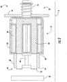
- FIG. 2 shows an embodiment of an electromagnetic safety trigger 40 for an elevator safety system in a normal operating state.
- the electromagnetic safety trigger 40 includes an electromagnetic component 42 and a magnetic brake 44.
- the electromagnetic component 42 includes a coil 46 and a core 48 disposed within a housing 50.
- the electromagnetic component 42 further includes a retention apparatus 52.
- the retention apparatus 52 includes a housing wall 54 and at least one resetting spring 56.
- the at least one resetting spring 56 is configured to move the electromagnetic component 42 in a direction parallel to the axis A.
- the housing wall 54 may be flexible and configured to move the electromagnetic component 42 in a direction parallel to the axis A.
- the magnetic brake 44 includes a holder 58 having a first end 60 and a brake portion 62 disposed on a second end 64.
- a magnet 66 is disposed within the holder 58, and configured to magnetically couple the magnetic brake 44 to the electromagnetic component 42 in a non-engaging position and to a metal component of the system (e.g. the guide rails 20) in an engaging position.
- the magnetic brake 44 is attracted and held to the electromagnetic component 42 via the core 48.
- the at least one resetting spring 56 is operative to hold the electromagnetic component 42 in normal operating state (i.e. non-engaging position).
- the at least one resetting spring 56 includes a preset tension such that the attraction force between the magnetic brake 44 and the guide rails 20 is far less than the holding force provided by the at least one resetting spring 56.
- the electromagnetic component 42 propels the magnetic brake 44 towards the guide rail 20 as shown in FIGs. 3 and 4 .
- the safety 24 is pushed in an upward direction by a small linkage bar 66 operably coupled to the safety 24 and the magnetic brake 44 when relative motion is created by the magnetic brake 44 sticking to the guide rail 20.
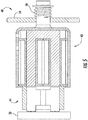
- FIG. 5 shows the electromagnetic safety trigger 40 in a transition state from a braking state to a non-braking state.
- electromagnetic safety trigger 40 While the embodiment of the electromagnetic safety trigger 40 is shown in use with an elevator system 10, it will be appreciated that the electromagnetic safety trigger 40 may be suitable for any large stroke range application, such as a rotary arrangement and linear arrangement machines to name a couple of non-limiting example.
- FIGs. 6-8 show the electromagnetic safety trigger 40 with a rotary arrangement machine 70.
- One or more electromagnetic safety triggers 40 are shown disposed within a stationary housing, and located adjacent to the rotary arrangement machine 70. As the magnetic brake 44 is propelled to fully engage the rotary arrangement machine 70, as shown in FIG. 8 , a portion of the magnetic brake 44 remains within the stationary housing 72 to arrest rotation of the rotary arrangement machine 70.
- the retention apparatus 52 may be moved in order to create a slimmer width of the safety trigger 40.
- FIGs. 9 and 10 are illustrated an embodiment of an electromagnetic safety trigger 40A for an elevator safety system in a normal operating state.
- the electromagnetic safety trigger 40A includes an electromagnetic component 42A and a magnetic brake 44.
- the electromagnetic component 42A includes a core 46A and a coil 48A attached to a housing 50A that passes through the core 46A.
- the housing 50A includes extending portions 80A.
- the electromagnetic component 42A further includes a retention apparatus 52A.
- the retention apparatus 52A includes a housing wall 54A, an opposing housing wall 54B, and at least one biasing member.
- the at least one biasing member comprises at least one resetting spring 56A.
- the at least one resetting springs 56A are configured to move the electromagnetic component 42A in a direction parallel to the axis A.
- the resetting springs 56A in the illustrated embodiment comprise compression conical springs that can compress to the diameter of the wire from which they are formed.
- FIG. 11 Another embodiment is shown in FIG. 11 , in which is illustrated an embodiment of an electromagnetic safety trigger 40B for an elevator safety system in a normal operating state.
- the electromagnetic safety trigger 40B includes an electromagnetic component 42B and a magnetic brake 44.
- the electromagnetic component 42B includes a core 46B and a coil 48A.
- the electromagnetic component 42B further includes a retention apparatus 52B.
- the retention apparatus 52B includes a housing wall 54A, an opposing housing wall 54B, and a resetting spring 56B.
- the resetting spring 56B comprises a leaf spring that extends between the housing wall 54B on one side of the electromagnetic component 42B, through the core 46B and to the housing wall 54B on one side of the electromagnetic component 42B.
- the resetting spring may extend in an arc only from the housing wall 54B to the electromagnetic component 42B on one side thereof. In other embodiments, this configuration of resetting spring 56B is disposed on either side of the electromagnetic component 42B, but the arced resetting springs 56B are not coupled together.
- the resetting spring 56B is configured to move the electromagnetic component 42B in a direction parallel to the axis A.
- FIG. 12 Another embodiment is shown in FIG. 12 , in which is illustrated an embodiment of an electromagnetic safety trigger 40C for an elevator safety system in a normal operating state.
- the electromagnetic safety trigger 40C includes an electromagnetic component 42C and a magnetic brake 44.
- the electromagnetic component 42C includes a core 46C and a coil 48A attached to a housing 50C that passes through the core 46C.
- the housing 50C includes extending portions 80C.
- the electromagnetic component 42C further includes a retention apparatus 52C.
- the retention apparatus 52C includes a housing wall 54C and at least one resetting spring 56C. In the illustrated embodiment, there are two resetting springs 56C disposed between the housing wall 54C and the extending portions 80C of the housing 50C.
- resetting springs 56C there may be fewer or greater than two resetting springs 56C.
- the resetting springs 56C in the illustrated embodiment comprise tension springs.
- the at least one resetting springs 56C are configured to move the electromagnetic component 42C in a direction parallel to the axis A.
- FIG. 13 Another embodiment is shown in FIG. 13 , in which is illustrated an embodiment of an electromagnetic safety trigger 40D for an elevator safety system in a normal operating state.
- the electromagnetic safety trigger 40D includes an electromagnetic component 42D and a magnetic brake 44.
- the electromagnetic component 42D includes a core 46D and a coil 48A attached to a housing 50D that passes through the core 46D.
- the housing 50D includes extending portions 80D.
- the electromagnetic component 42D further includes a retention apparatus 52D.
- the retention apparatus 52D includes a housing wall 54A, an opposing housing wall 54B, and at least one resetting spring 56D. In the illustrated embodiment, there are two resetting springs 56D disposed between the housing wall 54B and the extending portions 80D of the housing 50D.
- the at least one resetting springs 56D are configured to move the electromagnetic component 42D in a direction parallel to the axis A.
- the resetting springs 56D in the illustrated embodiment comprise compressible foam members that return to their original shape when the compressive force acting upon them is sufficiently low.
- the resetting springs 56 may be moved to a location behind the core 46/coil 48 (i.e., into the page) and/or to a location in front of the core 46/coil 48 (i.e., out of the page). Such positioning will reduce the height of the electromagnetic safety trigger 40.
- FIG. 14 Another embodiment is shown in FIG. 14 , in which is illustrated an embodiment of an electromagnetic safety trigger 40E for an elevator safety system in a normal operating state.
- the electromagnetic safety trigger 40E includes an electromagnetic component 42E and a magnetic brake 44.
- the electromagnetic component 42E includes a core 46E and a coil 48A attached to a housing 50E.
- the housing 50E includes an extending portion 80E.
- the electromagnetic component 42E further includes a retention apparatus 52E.
- the retention apparatus 52E includes a motor 90 driving a threaded shaft 92.
- the threaded shaft 92 threadingly engages a threaded hole formed through the extending portion 80E.
- the present embodiments include an electromagnetic safety trigger 40 having a retention apparatus 52 capable of generating enough force to disengage the magnetic brake 44 from a metal component of the system during a reset condition.
Landscapes
- Engineering & Computer Science (AREA)
- Mechanical Engineering (AREA)
- Cage And Drive Apparatuses For Elevators (AREA)
- Maintenance And Inspection Apparatuses For Elevators (AREA)
- Braking Arrangements (AREA)
Claims (3)
- Dispositif de freinage à fonctionnement sélectif pour un système d'ascenseur (10) comportant une cabine (16) et une pluralité de rails de guidage (20), comprenant :un frein de sécurité (24) disposé sur la cabine (16) et conçu pour être calé contre l'un des rails de guidage (20) lorsqu'il passe d'un état de non-freinage à un état de freinage ;une tige (66) couplée de manière opérationnelle au frein de sécurité (24), la tige (66) étant conçue pour faire passer le frein de sécurité (24) de l'état de non-freinage à l'état de freinage ;un frein magnétique (44) couplé de manière opérationnelle à la tige (66) et disposé à côté du rail de guidage (20), le frein magnétique (44) étant conçu pour passer d'une position de mise en prise de rail à une position de non-mise en prise de rail, ledit frein magnétique (44), lorsqu'il est en position de mise en prise de rail simultanément avec le mouvement de la cabine (16), déplaçant la tige (66) dans une direction afin de faire passer le frein de sécurité (24) de l'état de non-freinage à l'état de freinage ; etun composant électromagnétique (42 ; 42A ; 42B ; 42C ; 42D ; 42E), le composant électromagnétique (42 ; 42A ; 42B ; 42C ; 42D ; 42E) étant conçu pour faire passer le frein magnétique (44) de la position de mise en prise de rail à la position de non-mise en prise de rail à la réception d'un signal de réinitialisation ;dans lequel le composant électromagnétique (42 ; 42A ; 42B ; 42C ; 42D ; 42E) comprend en outre un appareil de retenue (52 ; 52A ; 52B ; 52C ; 52D ; 52E) caractérisé en ce que :l'appareil de retenue (52 ; 52A ; 52B ; 52C ; 52D ; 52E) est conçu pour déplacer le composant électromagnétique (42 ; 42A ; 42B ; 42C ; 42D ; 42E) dans une direction parallèle à un axe d'actionnement ;dans lequel l'appareil de retenue (52 ; 52A ; 52B ; 52C ; 52D ; 52E) comprend un élément de sollicitation (56 ; 56A ; 56B ; 56C ; 56D) conçu pour appliquer une force au composant électromagnétique (42 ; 42A ; 42B ; 42C ; 42D ; 42E) dans la direction parallèle à l'axe d'actionnement ; etdans lequel l'élément de sollicitation (56 ; 56A ; 56B ; 56C ; 56D) comprend au moins l'un parmi : un ressort conique de compression (56A), un ressort à lame (56B), un ressort de tension (56C) ou un élément en mousse compressible (56D).
- Dispositif de freinage selon la revendication 1, dans lequel l'appareil de retenue (52 ; 52A ; 52B ; 52C ; 52D ; 52E) comprend en outre une paroi de boîtier (54A ; 54B ; 54C), dans lequel l'élément de sollicitation (56 ; 56A ; 56B ; 56C ; 56D) est disposé entre la paroi de boîtier (54A ; 54B ; 54C) et le composant électromagnétique (42 ; 42A ; 42B ; 42C ; 42D ; 42E), dans lequel l'élément de sollicitation permet d'appliquer la force au composant électromagnétique (42 ; 42A ; 42B ; 42C ; 42D ; 42E) dans la direction parallèle à l'axe d'actionnement.
- Dispositif de freinage selon une quelconque revendication précédente, dans lequel l'appareil de retenue comprend en outre :un moteur (90) ; etun arbre fileté (92) couplé de manière opérationnelle au moteur (90) afin d'entraîner sa rotation par le moteur (90) ;dans lequel l'arbre fileté (92) est en outre couplé par filetage au composant électromagnétique (42 ; 42A ; 42B ; 42C ; 42D ; 42E) de sorte que la rotation de l'arbre fileté (92) par le moteur (90) amène le composant électromagnétique (42 ; 42A ; 42B ; 42C ; 42D ; 42E) à se déplacer dans la direction parallèle à l'axe d'actionnement.
Applications Claiming Priority (1)
| Application Number | Priority Date | Filing Date | Title |
|---|---|---|---|
| US15/947,328 US11066274B2 (en) | 2015-06-30 | 2018-04-06 | Electromagnetic safety trigger |
Publications (3)
| Publication Number | Publication Date |
|---|---|
| EP3587328A2 EP3587328A2 (fr) | 2020-01-01 |
| EP3587328A3 EP3587328A3 (fr) | 2020-01-29 |
| EP3587328B1 true EP3587328B1 (fr) | 2021-11-17 |
Family
ID=66092162
Family Applications (1)
| Application Number | Title | Priority Date | Filing Date |
|---|---|---|---|
| EP19167273.2A Active EP3587328B1 (fr) | 2018-04-06 | 2019-04-04 | Déclencheur électromagnétique de sécurité |
Country Status (2)
| Country | Link |
|---|---|
| EP (1) | EP3587328B1 (fr) |
| CN (1) | CN110342367B (fr) |
Families Citing this family (3)
| Publication number | Priority date | Publication date | Assignee | Title |
|---|---|---|---|---|
| US11724908B2 (en) * | 2020-06-24 | 2023-08-15 | Otis Elevator Company | Electronic actuation module for elevator safety brake system |
| EP3981722B1 (fr) * | 2020-10-07 | 2024-04-10 | Otis Elevator Company | Dispositif de frein de sécurité |
| US11597631B2 (en) * | 2021-05-18 | 2023-03-07 | Otis Elevator Company | Magnet assemblies of electromechanical actuators for elevator systems having encapsulated switch |
Family Cites Families (4)
| Publication number | Priority date | Publication date | Assignee | Title |
|---|---|---|---|---|
| CN1789102B (zh) * | 2004-12-17 | 2010-12-08 | 中国建筑科学研究院建筑机械化研究分院 | 电梯超速保护装置 |
| EP2084095B1 (fr) * | 2006-11-08 | 2011-04-06 | Otis Elevator Company | Dispositif de freinage d'un ascenseur |
| WO2017087978A1 (fr) * | 2015-11-20 | 2017-05-26 | Otis Elevator Company | Actionneur à verrou électronique |
| US10584014B2 (en) * | 2015-12-07 | 2020-03-10 | Otis Elevator Company | Robust electrical safety actuation module |
-
2019
- 2019-04-04 CN CN201910271150.9A patent/CN110342367B/zh active Active
- 2019-04-04 EP EP19167273.2A patent/EP3587328B1/fr active Active
Also Published As
| Publication number | Publication date |
|---|---|
| CN110342367A (zh) | 2019-10-18 |
| EP3587328A3 (fr) | 2020-01-29 |
| EP3587328A2 (fr) | 2020-01-01 |
| CN110342367B (zh) | 2021-08-31 |
Similar Documents
| Publication | Publication Date | Title |
|---|---|---|
| EP3112306B1 (fr) | Soupape électromagnétique de sécurité | |
| US11066274B2 (en) | Electromagnetic safety trigger | |
| EP3377434B1 (fr) | Actionneur à verrou électronique | |
| EP3447017B1 (fr) | Actionneur de sécurité électronique synchronisé | |
| EP3231756B1 (fr) | Dispositif d'actionnement de sécurité électronique ayant un ensemble d'alimentation | |
| EP3141511B1 (fr) | Assemblage de boîtier pour un dispositif d'actionnement de sécurité | |
| EP3587328B1 (fr) | Déclencheur électromagnétique de sécurité | |
| EP4140931B1 (fr) | Système de freinage de sécurité | |
| US11939189B2 (en) | Frictionless electronic safety actuator | |
| US11858781B2 (en) | Frictionless electronic safety actuator | |
| EP4378874B1 (fr) | Actionneur de frein de sécurité d'ascenseur sans frottement | |
| US11970367B2 (en) | Safety brake actuator | |
| EP4378875A1 (fr) | Actionneur de frein de sécurité sans frottement | |
| EP4289776B1 (fr) | Réinitialisation d'un actionneur de sécurité dans un système d'ascenseur | |
| EP4332041B1 (fr) | Actionneur de frein de sécurité sans friction |
Legal Events
| Date | Code | Title | Description |
|---|---|---|---|
| PUAI | Public reference made under article 153(3) epc to a published international application that has entered the european phase |
Free format text: ORIGINAL CODE: 0009012 |
|
| STAA | Information on the status of an ep patent application or granted ep patent |
Free format text: STATUS: THE APPLICATION HAS BEEN PUBLISHED |
|
| PUAL | Search report despatched |
Free format text: ORIGINAL CODE: 0009013 |
|
| AK | Designated contracting states |
Kind code of ref document: A2 Designated state(s): AL AT BE BG CH CY CZ DE DK EE ES FI FR GB GR HR HU IE IS IT LI LT LU LV MC MK MT NL NO PL PT RO RS SE SI SK SM TR |
|
| AX | Request for extension of the european patent |
Extension state: BA ME |
|
| AK | Designated contracting states |
Kind code of ref document: A3 Designated state(s): AL AT BE BG CH CY CZ DE DK EE ES FI FR GB GR HR HU IE IS IT LI LT LU LV MC MK MT NL NO PL PT RO RS SE SI SK SM TR |
|
| AX | Request for extension of the european patent |
Extension state: BA ME |
|
| RIC1 | Information provided on ipc code assigned before grant |
Ipc: B66B 5/22 20060101AFI20191220BHEP |
|
| STAA | Information on the status of an ep patent application or granted ep patent |
Free format text: STATUS: REQUEST FOR EXAMINATION WAS MADE |
|
| 17P | Request for examination filed |
Effective date: 20200729 |
|
| RBV | Designated contracting states (corrected) |
Designated state(s): AL AT BE BG CH CY CZ DE DK EE ES FI FR GB GR HR HU IE IS IT LI LT LU LV MC MK MT NL NO PL PT RO RS SE SI SK SM TR |
|
| GRAP | Despatch of communication of intention to grant a patent |
Free format text: ORIGINAL CODE: EPIDOSNIGR1 |
|
| STAA | Information on the status of an ep patent application or granted ep patent |
Free format text: STATUS: GRANT OF PATENT IS INTENDED |
|
| INTG | Intention to grant announced |
Effective date: 20210618 |
|
| GRAS | Grant fee paid |
Free format text: ORIGINAL CODE: EPIDOSNIGR3 |
|
| GRAA | (expected) grant |
Free format text: ORIGINAL CODE: 0009210 |
|
| STAA | Information on the status of an ep patent application or granted ep patent |
Free format text: STATUS: THE PATENT HAS BEEN GRANTED |
|
| AK | Designated contracting states |
Kind code of ref document: B1 Designated state(s): AL AT BE BG CH CY CZ DE DK EE ES FI FR GB GR HR HU IE IS IT LI LT LU LV MC MK MT NL NO PL PT RO RS SE SI SK SM TR |
|
| REG | Reference to a national code |
Ref country code: GB Ref legal event code: FG4D |
|
| REG | Reference to a national code |
Ref country code: IE Ref legal event code: FG4D |
|
| REG | Reference to a national code |
Ref country code: DE Ref legal event code: R096 Ref document number: 602019009270 Country of ref document: DE |
|
| REG | Reference to a national code |
Ref country code: AT Ref legal event code: REF Ref document number: 1447896 Country of ref document: AT Kind code of ref document: T Effective date: 20211215 |
|
| REG | Reference to a national code |
Ref country code: LT Ref legal event code: MG9D |
|
| REG | Reference to a national code |
Ref country code: NL Ref legal event code: MP Effective date: 20211117 |
|
| REG | Reference to a national code |
Ref country code: AT Ref legal event code: MK05 Ref document number: 1447896 Country of ref document: AT Kind code of ref document: T Effective date: 20211117 |
|
| PG25 | Lapsed in a contracting state [announced via postgrant information from national office to epo] |
Ref country code: RS Free format text: LAPSE BECAUSE OF FAILURE TO SUBMIT A TRANSLATION OF THE DESCRIPTION OR TO PAY THE FEE WITHIN THE PRESCRIBED TIME-LIMIT Effective date: 20211117 Ref country code: LT Free format text: LAPSE BECAUSE OF FAILURE TO SUBMIT A TRANSLATION OF THE DESCRIPTION OR TO PAY THE FEE WITHIN THE PRESCRIBED TIME-LIMIT Effective date: 20211117 Ref country code: FI Free format text: LAPSE BECAUSE OF FAILURE TO SUBMIT A TRANSLATION OF THE DESCRIPTION OR TO PAY THE FEE WITHIN THE PRESCRIBED TIME-LIMIT Effective date: 20211117 Ref country code: BG Free format text: LAPSE BECAUSE OF FAILURE TO SUBMIT A TRANSLATION OF THE DESCRIPTION OR TO PAY THE FEE WITHIN THE PRESCRIBED TIME-LIMIT Effective date: 20220217 Ref country code: AT Free format text: LAPSE BECAUSE OF FAILURE TO SUBMIT A TRANSLATION OF THE DESCRIPTION OR TO PAY THE FEE WITHIN THE PRESCRIBED TIME-LIMIT Effective date: 20211117 |
|
| PG25 | Lapsed in a contracting state [announced via postgrant information from national office to epo] |
Ref country code: IS Free format text: LAPSE BECAUSE OF FAILURE TO SUBMIT A TRANSLATION OF THE DESCRIPTION OR TO PAY THE FEE WITHIN THE PRESCRIBED TIME-LIMIT Effective date: 20220317 Ref country code: SE Free format text: LAPSE BECAUSE OF FAILURE TO SUBMIT A TRANSLATION OF THE DESCRIPTION OR TO PAY THE FEE WITHIN THE PRESCRIBED TIME-LIMIT Effective date: 20211117 Ref country code: PT Free format text: LAPSE BECAUSE OF FAILURE TO SUBMIT A TRANSLATION OF THE DESCRIPTION OR TO PAY THE FEE WITHIN THE PRESCRIBED TIME-LIMIT Effective date: 20220317 Ref country code: PL Free format text: LAPSE BECAUSE OF FAILURE TO SUBMIT A TRANSLATION OF THE DESCRIPTION OR TO PAY THE FEE WITHIN THE PRESCRIBED TIME-LIMIT Effective date: 20211117 Ref country code: NO Free format text: LAPSE BECAUSE OF FAILURE TO SUBMIT A TRANSLATION OF THE DESCRIPTION OR TO PAY THE FEE WITHIN THE PRESCRIBED TIME-LIMIT Effective date: 20220217 Ref country code: NL Free format text: LAPSE BECAUSE OF FAILURE TO SUBMIT A TRANSLATION OF THE DESCRIPTION OR TO PAY THE FEE WITHIN THE PRESCRIBED TIME-LIMIT Effective date: 20211117 Ref country code: LV Free format text: LAPSE BECAUSE OF FAILURE TO SUBMIT A TRANSLATION OF THE DESCRIPTION OR TO PAY THE FEE WITHIN THE PRESCRIBED TIME-LIMIT Effective date: 20211117 Ref country code: HR Free format text: LAPSE BECAUSE OF FAILURE TO SUBMIT A TRANSLATION OF THE DESCRIPTION OR TO PAY THE FEE WITHIN THE PRESCRIBED TIME-LIMIT Effective date: 20211117 Ref country code: GR Free format text: LAPSE BECAUSE OF FAILURE TO SUBMIT A TRANSLATION OF THE DESCRIPTION OR TO PAY THE FEE WITHIN THE PRESCRIBED TIME-LIMIT Effective date: 20220218 Ref country code: ES Free format text: LAPSE BECAUSE OF FAILURE TO SUBMIT A TRANSLATION OF THE DESCRIPTION OR TO PAY THE FEE WITHIN THE PRESCRIBED TIME-LIMIT Effective date: 20211117 |
|
| PG25 | Lapsed in a contracting state [announced via postgrant information from national office to epo] |
Ref country code: SM Free format text: LAPSE BECAUSE OF FAILURE TO SUBMIT A TRANSLATION OF THE DESCRIPTION OR TO PAY THE FEE WITHIN THE PRESCRIBED TIME-LIMIT Effective date: 20211117 Ref country code: SK Free format text: LAPSE BECAUSE OF FAILURE TO SUBMIT A TRANSLATION OF THE DESCRIPTION OR TO PAY THE FEE WITHIN THE PRESCRIBED TIME-LIMIT Effective date: 20211117 Ref country code: RO Free format text: LAPSE BECAUSE OF FAILURE TO SUBMIT A TRANSLATION OF THE DESCRIPTION OR TO PAY THE FEE WITHIN THE PRESCRIBED TIME-LIMIT Effective date: 20211117 Ref country code: EE Free format text: LAPSE BECAUSE OF FAILURE TO SUBMIT A TRANSLATION OF THE DESCRIPTION OR TO PAY THE FEE WITHIN THE PRESCRIBED TIME-LIMIT Effective date: 20211117 Ref country code: DK Free format text: LAPSE BECAUSE OF FAILURE TO SUBMIT A TRANSLATION OF THE DESCRIPTION OR TO PAY THE FEE WITHIN THE PRESCRIBED TIME-LIMIT Effective date: 20211117 Ref country code: CZ Free format text: LAPSE BECAUSE OF FAILURE TO SUBMIT A TRANSLATION OF THE DESCRIPTION OR TO PAY THE FEE WITHIN THE PRESCRIBED TIME-LIMIT Effective date: 20211117 |
|
| REG | Reference to a national code |
Ref country code: DE Ref legal event code: R097 Ref document number: 602019009270 Country of ref document: DE |
|
| PLBE | No opposition filed within time limit |
Free format text: ORIGINAL CODE: 0009261 |
|
| STAA | Information on the status of an ep patent application or granted ep patent |
Free format text: STATUS: NO OPPOSITION FILED WITHIN TIME LIMIT |
|
| 26N | No opposition filed |
Effective date: 20220818 |
|
| PG25 | Lapsed in a contracting state [announced via postgrant information from national office to epo] |
Ref country code: AL Free format text: LAPSE BECAUSE OF FAILURE TO SUBMIT A TRANSLATION OF THE DESCRIPTION OR TO PAY THE FEE WITHIN THE PRESCRIBED TIME-LIMIT Effective date: 20211117 |
|
| PG25 | Lapsed in a contracting state [announced via postgrant information from national office to epo] |
Ref country code: SI Free format text: LAPSE BECAUSE OF FAILURE TO SUBMIT A TRANSLATION OF THE DESCRIPTION OR TO PAY THE FEE WITHIN THE PRESCRIBED TIME-LIMIT Effective date: 20211117 |
|
| REG | Reference to a national code |
Ref country code: CH Ref legal event code: PL |
|
| REG | Reference to a national code |
Ref country code: BE Ref legal event code: MM Effective date: 20220430 |
|
| PG25 | Lapsed in a contracting state [announced via postgrant information from national office to epo] |
Ref country code: MC Free format text: LAPSE BECAUSE OF FAILURE TO SUBMIT A TRANSLATION OF THE DESCRIPTION OR TO PAY THE FEE WITHIN THE PRESCRIBED TIME-LIMIT Effective date: 20211117 Ref country code: LU Free format text: LAPSE BECAUSE OF NON-PAYMENT OF DUE FEES Effective date: 20220404 Ref country code: LI Free format text: LAPSE BECAUSE OF NON-PAYMENT OF DUE FEES Effective date: 20220430 Ref country code: CH Free format text: LAPSE BECAUSE OF NON-PAYMENT OF DUE FEES Effective date: 20220430 |
|
| PG25 | Lapsed in a contracting state [announced via postgrant information from national office to epo] |
Ref country code: BE Free format text: LAPSE BECAUSE OF NON-PAYMENT OF DUE FEES Effective date: 20220430 |
|
| PG25 | Lapsed in a contracting state [announced via postgrant information from national office to epo] |
Ref country code: IE Free format text: LAPSE BECAUSE OF NON-PAYMENT OF DUE FEES Effective date: 20220404 |
|
| PG25 | Lapsed in a contracting state [announced via postgrant information from national office to epo] |
Ref country code: IT Free format text: LAPSE BECAUSE OF FAILURE TO SUBMIT A TRANSLATION OF THE DESCRIPTION OR TO PAY THE FEE WITHIN THE PRESCRIBED TIME-LIMIT Effective date: 20211117 |
|
| GBPC | Gb: european patent ceased through non-payment of renewal fee |
Effective date: 20230404 |
|
| PG25 | Lapsed in a contracting state [announced via postgrant information from national office to epo] |
Ref country code: GB Free format text: LAPSE BECAUSE OF NON-PAYMENT OF DUE FEES Effective date: 20230404 |
|
| PG25 | Lapsed in a contracting state [announced via postgrant information from national office to epo] |
Ref country code: GB Free format text: LAPSE BECAUSE OF NON-PAYMENT OF DUE FEES Effective date: 20230404 |
|
| PG25 | Lapsed in a contracting state [announced via postgrant information from national office to epo] |
Ref country code: MK Free format text: LAPSE BECAUSE OF FAILURE TO SUBMIT A TRANSLATION OF THE DESCRIPTION OR TO PAY THE FEE WITHIN THE PRESCRIBED TIME-LIMIT Effective date: 20211117 Ref country code: CY Free format text: LAPSE BECAUSE OF FAILURE TO SUBMIT A TRANSLATION OF THE DESCRIPTION OR TO PAY THE FEE WITHIN THE PRESCRIBED TIME-LIMIT Effective date: 20211117 |
|
| PG25 | Lapsed in a contracting state [announced via postgrant information from national office to epo] |
Ref country code: HU Free format text: LAPSE BECAUSE OF FAILURE TO SUBMIT A TRANSLATION OF THE DESCRIPTION OR TO PAY THE FEE WITHIN THE PRESCRIBED TIME-LIMIT; INVALID AB INITIO Effective date: 20190404 |
|
| PG25 | Lapsed in a contracting state [announced via postgrant information from national office to epo] |
Ref country code: TR Free format text: LAPSE BECAUSE OF FAILURE TO SUBMIT A TRANSLATION OF THE DESCRIPTION OR TO PAY THE FEE WITHIN THE PRESCRIBED TIME-LIMIT Effective date: 20211117 |
|
| PG25 | Lapsed in a contracting state [announced via postgrant information from national office to epo] |
Ref country code: MT Free format text: LAPSE BECAUSE OF FAILURE TO SUBMIT A TRANSLATION OF THE DESCRIPTION OR TO PAY THE FEE WITHIN THE PRESCRIBED TIME-LIMIT Effective date: 20211117 |
|
| PGFP | Annual fee paid to national office [announced via postgrant information from national office to epo] |
Ref country code: DE Payment date: 20250319 Year of fee payment: 7 |
|
| PGFP | Annual fee paid to national office [announced via postgrant information from national office to epo] |
Ref country code: FR Payment date: 20260319 Year of fee payment: 8 |